EP2388846A1 - Secondary battery - Google Patents
Secondary battery Download PDFInfo
- Publication number
- EP2388846A1 EP2388846A1 EP11154791A EP11154791A EP2388846A1 EP 2388846 A1 EP2388846 A1 EP 2388846A1 EP 11154791 A EP11154791 A EP 11154791A EP 11154791 A EP11154791 A EP 11154791A EP 2388846 A1 EP2388846 A1 EP 2388846A1
- Authority
- EP
- European Patent Office
- Prior art keywords
- film unit
- secondary battery
- unit
- case
- break
- Prior art date
- Legal status (The legal status is an assumption and is not a legal conclusion. Google has not performed a legal analysis and makes no representation as to the accuracy of the status listed.)
- Granted
Links
Images




Classifications
-
- H—ELECTRICITY
- H01—ELECTRIC ELEMENTS
- H01M—PROCESSES OR MEANS, e.g. BATTERIES, FOR THE DIRECT CONVERSION OF CHEMICAL ENERGY INTO ELECTRICAL ENERGY
- H01M50/00—Constructional details or processes of manufacture of the non-active parts of electrochemical cells other than fuel cells, e.g. hybrid cells
- H01M50/30—Arrangements for facilitating escape of gases
- H01M50/342—Non-re-sealable arrangements
- H01M50/3425—Non-re-sealable arrangements in the form of rupturable membranes or weakened parts, e.g. pierced with the aid of a sharp member
-
- H—ELECTRICITY
- H01—ELECTRIC ELEMENTS
- H01M—PROCESSES OR MEANS, e.g. BATTERIES, FOR THE DIRECT CONVERSION OF CHEMICAL ENERGY INTO ELECTRICAL ENERGY
- H01M10/00—Secondary cells; Manufacture thereof
- H01M10/02—Details
-
- H—ELECTRICITY
- H01—ELECTRIC ELEMENTS
- H01M—PROCESSES OR MEANS, e.g. BATTERIES, FOR THE DIRECT CONVERSION OF CHEMICAL ENERGY INTO ELECTRICAL ENERGY
- H01M50/00—Constructional details or processes of manufacture of the non-active parts of electrochemical cells other than fuel cells, e.g. hybrid cells
- H01M50/10—Primary casings; Jackets or wrappings
- H01M50/147—Lids or covers
-
- H—ELECTRICITY
- H01—ELECTRIC ELEMENTS
- H01M—PROCESSES OR MEANS, e.g. BATTERIES, FOR THE DIRECT CONVERSION OF CHEMICAL ENERGY INTO ELECTRICAL ENERGY
- H01M50/00—Constructional details or processes of manufacture of the non-active parts of electrochemical cells other than fuel cells, e.g. hybrid cells
- H01M50/10—Primary casings; Jackets or wrappings
- H01M50/183—Sealing members
-
- H—ELECTRICITY
- H01—ELECTRIC ELEMENTS
- H01M—PROCESSES OR MEANS, e.g. BATTERIES, FOR THE DIRECT CONVERSION OF CHEMICAL ENERGY INTO ELECTRICAL ENERGY
- H01M50/00—Constructional details or processes of manufacture of the non-active parts of electrochemical cells other than fuel cells, e.g. hybrid cells
- H01M50/30—Arrangements for facilitating escape of gases
- H01M50/342—Non-re-sealable arrangements
-
- H—ELECTRICITY
- H01—ELECTRIC ELEMENTS
- H01M—PROCESSES OR MEANS, e.g. BATTERIES, FOR THE DIRECT CONVERSION OF CHEMICAL ENERGY INTO ELECTRICAL ENERGY
- H01M50/00—Constructional details or processes of manufacture of the non-active parts of electrochemical cells other than fuel cells, e.g. hybrid cells
- H01M50/50—Current conducting connections for cells or batteries
- H01M50/543—Terminals
-
- Y—GENERAL TAGGING OF NEW TECHNOLOGICAL DEVELOPMENTS; GENERAL TAGGING OF CROSS-SECTIONAL TECHNOLOGIES SPANNING OVER SEVERAL SECTIONS OF THE IPC; TECHNICAL SUBJECTS COVERED BY FORMER USPC CROSS-REFERENCE ART COLLECTIONS [XRACs] AND DIGESTS
- Y02—TECHNOLOGIES OR APPLICATIONS FOR MITIGATION OR ADAPTATION AGAINST CLIMATE CHANGE
- Y02E—REDUCTION OF GREENHOUSE GAS [GHG] EMISSIONS, RELATED TO ENERGY GENERATION, TRANSMISSION OR DISTRIBUTION
- Y02E60/00—Enabling technologies; Technologies with a potential or indirect contribution to GHG emissions mitigation
- Y02E60/10—Energy storage using batteries
Definitions
- the present invention relates to secondary batteries.
- the first film unit may be detachable from the case along the break unit.
- the break unit may include at least one cutting-plane line formed on a part of an edge of the first film unit, and a connecting line may integrally connect the first and second film units.
- the first film unit may have a rectangular shape
- the break unit may be a cutting-plane line formed on at least a part of an edge of the first film unit, and at least another part of the edge of the first film unit may be integral with the second film unit.
- the break unit may be a break line formed on at least a part of an edge of the first film unit.
- the first film unit may have a rectangular shape, the break unit may be a break line formed on at least a part of an edge of the first film unit, and at least another part of the edge of the first film unit may be integrally formed with the second film unit.
- the break unit may be a cutting-plane line having at least a portion in a center region of the first film unit.
- the break unit may be a break line having at least a portion in a center region of the first film unit.
- the safety vent may be integral with the first side of the case.
- the secondary battery may further include a cap plate on the first side of the case, the cap plate being between the case and the film unit.
- the secondary battery 100 may include the electrode assembly 10, a cap plate 30, a case 40, and a film unit 90.
- the secondary battery 100 is a lithium-ion secondary battery constituting a prismatic battery, but is not limited thereto.
- the secondary battery 100 may be any of various types of batteries, e.g., a nickel-cadmium secondary battery, a nickel-hydrogen secondary battery, or a lithium battery, aside from a lithium-ion secondary battery.
- a shape of the secondary battery 100 is not limited to a quadrangular shape, and the case 40 of the secondary battery 100 may have any of various shapes, e.g., a cylindrical shape.
- the electrode assembly 10 may include a positive electrode 11, a negative electrode 12, and a separator 13.
- Positive and negative electrode current collecting units 50 and 60 may be electrically connected to the electrode assembly 10.
- the positive and negative electrode current collecting units 50 and 60 may be in the case 40.
- the case 40 accommodates the electrode assembly 10 therein with an electrolyte 70.
- the cap plate 30 may be combined to an open side, e.g., a first side 40a, of the case 40, thereby sealing the case 40 containing the electrode assembly 10 and the electrolyte 70.
- six sides of the case 40 may be sealed without having to use the cap plate 30.
- the positive electrode 11, the positive electrode current collector 51, and the positive electrode lead member 52, which are mutually electrically connected to each other, may include the same material, e.g., aluminum (Al).
- the negative electrode 12, the negative electrode current collector 61, and the negative electrode lead member 62, which are mutually electrically connected to each other may include the same material, e.g., copper (Cu).
- such materials are not limited thereto, and may vary.
- the electrode assembly 10 may have a jelly roll shape where the positive electrode 11, the separator 13, and the negative electrode 12 are wound up.
- the electrode assembly 10 may have any of various shapes, e.g., the positive electrode 11, the separator 13, and the negative electrode 12 may be alternately stacked on each other.
- the electrode assembly 10 is wound up by disposing the separator 13 as an insulator between the positive electrode 11 and the negative electrode 12.
- the case 40 accommodates the electrode assembly 10 therein with the electrolyte 70.
- the positive electrode terminal 21 and the negative electrode terminal 22 are respectively electrically connected to the positive electrode 11 and the negative electrode 12 of the electrode assembly 10, and are exposed outside of the case 40.
- the cap plate 30 is connected to the open side of the case 40.
- the positive electrode 11 may include a positive electrode plain unit 11a and a positive electrode coating unit 11b
- the negative electrode 12 may include a negative electrode plain unit 12a and a negative electrode coating unit 12b.
- the positive and negative electrode plain units 11a and 12a refer to respective areas on the positive and negative electrode current collectors 51 and 61, e.g., which are formed of thin metal foils, where an active material is not coated.
- the positive and negative electrode coating units 11b and 12b refer to respective areas on the positive and negative electrode current collectors 51 and 61 where an active material is coated.
- the positive electrode plain unit 11a may be formed on one side end of the positive electrode 11 along a length direction of the positive electrode 11 on one side end of the electrode assembly 10.
- the negative electrode plain unit 12a may be formed on one side end of the negative electrode 12 along a length direction of the negative electrode 12 on another side end of the electrode assembly 10.
- the case 40 may be shaped, e.g., as a quadrangular can having an open side.
- the electrode assembly 10 and the electrolyte 70 may be accommodated in the case 40 via the open side of the case 40.
- the cap plate 30 covers the case 40 in such a way that the positive and negative electrode terminals 21 and 22 protrude externally with respect to the cap plate 30.
- a boundary between the case 40 and the cap plate 30 may be sealed.
- the case 40 and the cap plate 30 may be welded by a laser, thereby sealing the case 40 accommodating the electrode assembly 10 and the electrolyte 70.
- the cap plate 30 may be formed of a thin plate.
- An electrolyte inlet 38a for injecting the electrolyte 70 may be formed in the cap plate 30. After the electrolyte 70 is injected through the electrolyte inlet 38a, a sealing cap 38 may be inserted into the electrolyte inlet 38a.
- Positive and negative electrode terminal holes 21a and 22a may be formed in the cap plate 30, e.g., through the cap plate 30.
- the positive electrode terminal 21 may externally protrude through the positive electrode terminal hole 21 a
- the negative electrode terminal 22 may externally protrude through the negative electrode terminal hole 22a.
- the upper and lower gaskets 25 and 27 may be disposed between the cap plate 30 and the positive and negative electrode terminals 21 and 22, thereby insulating the cap plate 30 from each of the positive and negative electrode terminals 21 and 22.
- the lower gaskets 27 are inserted below the cap plate 30 through the positive and negative electrode terminal holes 21a and 22a, and the upper gaskets 25 are inserted above the cap plate 30.
- a washer 24 for buffering a clamping force may be installed on each of the upper gaskets 25.
- a screw thread may be formed on each of the positive and negative electrode terminals 21 and 22, and the positive and negative electrode terminals 21 and 22 may be respectively coupled to nuts 29 with the washers 24 therebetween. The nuts 29 support the positive and negative electrode terminals 21 and 22.
- the secondary battery 100 may have any of various structures.
- the electrode assembly 10 may include a center pin.
- the electrode assembly 10 may extend along, e.g., a Z-axis, instead of an X-axis as shown in FIG. 3 .
- at least one of the positive and negative electrode terminals 21 and 22 may be connected to the case 40.
- a composition of the secondary battery 100 is not limited to the current embodiment and may vary.
- a vent break line 30a1 is formed on the safety vent 30a, so that the safety vent 30a may be easily broken according to an internal pressure of the case 40.
- the vent break line 30a1 is sealed when the safety vent 30a is closed, i.e., before the safety vent 30a breaks.
- the film unit 90 may be disposed on one side of the case 40, e.g., on the first side 40a of the case 40. Since the cap plate 30 is on the first side 40a of the case 40, the film unit 90 may be disposed on the cap plate 30, e.g., on a surface of the cap plate 30 facing away from the electrode assembly 10.
- the film unit 90 may include a first film unit 90a and a second film unit 90b.
- the first and second film units 90a and 90b may be integral with each other and substantially coplanar, and the second film unit 90b may surround, e.g., completely surround a perimeter of, the first film unit 90a.
- the first film unit 90a may be disposed on one side of the case 40 or on the cap plate 30, and may cover, e.g., overlap, at least a part of the safety vent 30a.
- the second film unit 90b may extend from the first film unit 90a.
- the film unit 90 may cover the entire open side of the case 40.
- the first film unit 90a may prevent foreign substances from entering the safety vent 30a. Accordingly, the first film unit 90a may cover at least a part of the safety vent 30a.
- a break unit 90a' may be formed on an edge of or on an inner part of the first film unit 90a, so as to form a path for the internal gas of the case 40 to pass through after the safety vent 30a is torn.
- the first film unit 90a may be positioned on the safety vent 30a to cover at least a part of the safety vent 30a, and at least a portion thereof may separate from, e.g., extend away from, the safety vent 30a via the break unit 90a' to enable gas release from an open safety vent 30a.
- FIG. 5 illustrates a schematic cross-sectional view of the film unit 90 along line V-V of FIG. 1 .
- an adhesive material may be applied only to the second film unit 90b, i.e., an adhesive material may not be adhered to an inner side 90ab of the first film unit 90a facing the cap plate 30.
- the first film unit 90a may scatter away from the film unit 90 during opening of the safety vent 30a due to an explosion, or the like. As such, if the first film unit 90a is separated and scattered from the film unit 90, safety may be decreased.
- an adhesive material may not be disposed between the first film unit 90a and the safety vent 30a, so the first film unit 90a may be prevented from being torn and scattered by sliding away from the safety vent 30a even when the safety vent 30a is opened due to an explosion, or the like.
- the break unit 90a' may be formed along an edge of or inside of the first film unit 90a, so that a part of the first film unit 90a may be easily separated from, i.e., detached from, the second film unit 90b or the safety vent 30a. As such, the gas emitted through the safety vent 30a may discharge through the partially opened first film unit 90a.
- the break unit 90a' may include three cutting-plane lines 90a1, 90a2, and 90a3 of the first film unit 90a separated from the second film unit 90b. In such a structure, the first film unit 90a may easily extend away from the second film unit 90b and the case 40 along the break unit 90a' when gas is discharged through the safety vent 30a.
- the break unit 90a' may be a cutting-plane line and/or a break line.
- the cutting plane line refers to a cut part penetrating through the first film unit 90a and completely separating the first film unit 90a from the second film unit 90b before and after the safety vent 30a opening.
- the break line refers to a punch dotted line at regular intervals penetrating the first film unit 90a and surrounding at least a part of the first film unit 90a, e.g., the first film unit 90a is only partially separated from the second film unit 90b before opening of the safety vent 30a.
- the break line may be a thin line that is easily cut or broken at regular intervals, e.g., without completely penetrating through the first film unit 90a, so the first film unit 90a may completely separate from the second film unit 90b through the break line only when the safety vent 30a is open.
- the break line is shown as a dotted line in the drawings ( FIGS. 7A-8A ), but may be a continuous line.
- a thickness of the break line, e.g., along the Z-axis, formed around the first film unit 90a may be relatively thin for easier cutting or tear-off according to an external pressure.
- the thickness of the film unit 90 may be about 1 mm, and the break line may form a notch of about 0.5 mm in the film unit 90.
- a thickness of the notch of the break line may be about 20% to about 80% of the thickness of the film unit 90.
- the shape and configuration of the break unit are not limited thereto, and may vary.
- a connection between the first film unit 90a and the second film unit 90b may be loosened, e.g., a connector (not shown) for connecting the first film unit 90a and the second film unit 90b may be formed of a material that is easily breakable.
- the break unit is not limited thereto.
- the cutting-plane lines 90a1, 90a2, and 90a3 may be formed along edges of the first film unit 90a, and the first film unit 90a may be connected to the second film unit 90b through the connecting side 90a4.
- the cutting-plane lines 90a1, 90a2 and 90a3, and the connecting side 90a4 may be arranged, so the shape of the first film unit 90a may correspond to the shape of the safety vent 30a.
- the first film unit 90a may be formed of a transparent material.
- the state of the safety vent 30a may be determined through the first film unit 90a, the state of the safety vent 30a may be determined without having to remove the first film unit 90a.
- the first film unit 90a not only the first film unit 90a, but also all parts of the second film unit 90b may be formed of a transparent material.
- an inner side 90b1 of the second film unit 90b may include an adhesive material so as to adhere the second film unit 90b to a side of the case 40 or a side of the cap plate 30.
- the second film unit 90b may insulate the cap plate 30.
- the second film unit 90b may include an insulating material.
- the insulating material may not only be included in the second film unit 90b, but may also be included in, e.g., all parts of or some parts of, the first film unit 90a.
- the second film unit 90b may extend to an edge of the cap plate 30. Also, as shown in FIG.
- holes h1 and h2 respectively corresponding to the positive and negative electrode terminals 21 and 22 extending from the electrode assembly 10 may be formed in the film unit 90, i.e., through the second film unit 90b.
- Second film units 190b, 290b, 390b, 490b, 590b, 690b, 790b, 890b, 990b, 1090b, 1190b, and 1290b illustrated in FIGS. 6A through 8B may perform the same or similar functions as the second film unit 90b of FIG. 1 , unless otherwise described.
- a secondary battery may include integrated first and second film units 90a and 90b in a single film unit 90 on the cap plate 30, so separate cap plate protecting film and vent protecting film may not be required.
- the film unit 90 may be formed by integrating the first film unit 90a, which operates as a vent protecting film, and the second film unit 90b, which operates as a cap plate protecting film, thereby improving process efficiency.
- the shape and size of the first film unit 90a may be variously adjusted. Also, the first film unit 90a may have any combination of a cutting-plane line and a break line. Different configurations of the film unit 90 will now be described in detail with reference to FIGS. 6A through 8B .
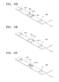
- FIGS. 6A through 6F illustrate various modified examples of the film unit 90 of FIG. 1
- FIGS. 7A through 7D illustrate other various modified examples of the film unit 90 of FIG. 1
- FIGS. 8A through 8B illustrate yet other various modified examples of the film unit 90 of FIG. 1 .
- an irregular cutting-plane line 290a1 may be formed inside a first film unit 290a.
- the irregular cutting-plane line 290a1 may divide the first film unit 290a into two separate parts.
- gas may easily be discharged from the safety vent 30a through the irregular cutting-plane line 290a1, i.e., between the two parts of the first film unit 290a.
- the first film unit 290a may not be separated and scatted from the second film unit 290b according to a shape of the irregular cutting-plane line 290a1 in the first film unit 290a.
- the film unit 490 of FIG. 6D is similar to the film unit 390 of FIG. 6C , with the exception of having a full cutting-plane line 490a1 along the y-axis and a partial cutting-plane line 490a2 along the x-axis.
- a linear portion of the second film unit 490b may extend through a center of the first film unit 490a along the y-axis.
- partial cutting-plane lines 590a1 and 590a2 may be formed around the first film unit 590a to form a gas discharge path.
- four portions of the first film unit 590a may define edges of a rectangle including a portion of the second film unit 590b in a center thereof.
- cutting-plane lines 690a1 may be formed inside the first film unit 690a to form a gas discharge path.
- the number of the cutting-plane lines 690a1 in FIG. 6F is four, but is not limited thereto, and may be less than or more than four.
- a break line may be formed on at least a part of an edge of or inside each of first film units 790a, 890a, 990a, and 1090a.
- the first film unit 790a may have a rectangular plane, and a break line 790a1 may be formed on at least a part of two sides and/or inside the first film unit 790a.
- the break line 790a1 may have a notch shape.
- a break line 890a1 may be formed around three sides of the first film unit 890a.
- the break line 890a1 may be formed on any one of the four sides of the first film unit 890a.
- a cutting-plane line or a break line may be both formed on each of the first film units 1190a and 1290a as shown in FIGS. 8A and 8B .
- a cutting-plane line 1190a2 may be formed inside the first film unit 1190a and a break line 1190a1 may be formed on an edge of the first film unit 1190a.
- a break line 1290a1 may be formed on one side of an edge of the first film unit 1290a and cutting-plane lines 1290a2 may be formed on other two sides of the edge of the first film unit 1290a.
- combinations of the cutting-plane line and the break line is not limited thereto, and may vary.
Landscapes
- Chemical & Material Sciences (AREA)
- Chemical Kinetics & Catalysis (AREA)
- Electrochemistry (AREA)
- General Chemical & Material Sciences (AREA)
- Engineering & Computer Science (AREA)
- Manufacturing & Machinery (AREA)
- Gas Exhaust Devices For Batteries (AREA)
- Connection Of Batteries Or Terminals (AREA)
Abstract
Description
- The present invention relates to secondary batteries.
- Unlike primary batteries, secondary batteries are rechargeable. Secondary batteries are widely used in high technology electronic equipments, e.g., cell phones, laptops, camcorders, cars, etc.
- A secondary battery may include an electrode assembly and an electrolyte. The electrode assembly may include a positive electrode plate, a negative electrode plate, and a separator therebetween. The electrolyte may include lithium ions. The positive electrode plate and the negative electrode plate of the electrode assembly may each include an electrode tab that protrudes outside of the electrode assembly.
- The electrode assembly is contained in a case, and an electrode terminal may be exposed outside of the case. The electrode tabs may externally protrude outside of the electrode assembly to electrically connect to the electrode terminal. The case may have, e.g., a cylindrical or quadrangle shape.
- One side of the case may be open, so the electrode assembly may be inserted into the case via the open side to be contained in the case. Here, a cap plate may cover the open side of the case. The electrode terminal electrically connected to the electrode assembly may penetrate the cap plate to protrude outside the cap. The electrode terminal and the cap plate may be electrically insulated from each other.
- Embodiments are directed to a secondary battery, which substantially overcomes one or more of the problems due to the limitations and disadvantages of the related art.
- It is therefore a feature of an embodiment to provide a secondary battery with a film unit that insulates a cap plate and prevents a foreign substance from being inserted into a safety vent.
- At least one of the above and other features and advantages may be realized by providing a secondary battery, including a case configured to accommodate an electrode assembly, a safety vent on a first side of the case, and a film unit disposed on the first side of the case, the film unit including a first film unit covering at least a part of the safety vent, the first film unit including a break unit, and a second film unit extending from the first film unit, the second film unit being adhered to the case.
- The electrode assembly may include at least one electrode terminal penetrating the first side of the case, and at least one hole corresponding to the at least one electrode terminal may be formed on the film unit.
- The first film unit may be detachable from the case along the break unit.
- The break unit may include at least one cutting-plane line formed on a part of an edge of the first film unit, and a connecting line may integrally connect the first and second film units.
- The first film unit may have a rectangular shape, the break unit may be a cutting-plane line formed on at least a part of an edge of the first film unit, and at least another part of the edge of the first film unit may be integral with the second film unit.
- The first film unit may have a triangular shape, the break unit may be a cutting-plane line formed on at least a part of an edge of the first film unit, and at least another part of the edge of the first film unit may be integral with the second film unit.
- The break unit may be a break line formed on at least a part of an edge of the first film unit. The first film unit may have a rectangular shape, the break unit may be a break line formed on at least a part of an edge of the first film unit, and at least another part of the edge of the first film unit may be integrally formed with the second film unit.
- The break unit may be a cutting-plane line having at least a portion in a center region of the first film unit.
- The break unit may be a break line having at least a portion in a center region of the first film unit.
- The safety vent may be integral with the first side of the case.
- The secondary battery may further include a cap plate on the first side of the case, the cap plate being between the case and the film unit.
- The second film unit may extend to an edge of the side of the case where the safety vent is disposed.
- A shape of the first film unit may correspond to a shape of the safety vent.
- The film unit may include an insulating material. The second film unit may include or consist of an insulating material.
- The film unit may include a transparent material. The first film unit may include or consist of a transparent material.
- The break unit may include a notch having a thickness from 20% to 80% of a thickness of the film unit. A thickness of the film unit may be 1 mm, and the notch may have a thickness of 0.5 mm.
- The above and other features and advantages will become more apparent to those of ordinary skill in the art by describing in detail exemplary embodiments with reference to the attached drawings, in which:
-
FIG. 1 illustrates a perspective schematic view of a secondary battery according to an embodiment; -
FIG. 2 illustrates a partial exploded perspective view of current collectors, lead members, - and an electrode assembly in the secondary battery of
FIG. 1 ; -
FIG. 3 illustrates a schematic cross-sectional view ofFIG. 1 ; -
FIGS. 4A and 4B illustrate schematic diagrams of a safety vent before and after being opened, respectively; -
FIG. 5 illustrates a schematic cross-sectional view taken along line V-V ofFIG. 1 ; -
FIGS. 6A through 6F illustrate various modified examples of a film unit ofFIG. 1 ; -
FIGS. 7A through 7D illustrate other various modified examples of the film unit ofFIG. 1 ; and -
FIGS. 8A through 8B illustrate other various modified examples of the film unit ofFIG. 1 . - Example embodiments will now be described more fully hereinafter with reference to the accompanying drawings.
- In the drawing figures, the dimensions of layers and regions may be exaggerated for clarity of illustration. It will also be understood that when a layer or element is referred to as being "on" another element, it can be directly on the other element, or intervening elements may also be present. In addition, it will also be understood that when an element is referred to as being "between" two elements, it can be the only element between the two elements, or one or more intervening elements may also be present. Like reference numerals refer to like elements throughout.
-
FIG. 1 illustrates a schematic perspective view of asecondary battery 100 according to an embodiment.FIG. 2 illustrates a partial exploded perspective view of positive and negative electrodecurrent collectors electrode lead members electrode assembly 10 in thesecondary battery 100 ofFIG. 1 .FIG. 3 illustrates a schematic cross-sectional view ofFIG. 1 . - Referring to
FIGS. 1 through 3 , thesecondary battery 100 may include theelectrode assembly 10, acap plate 30, acase 40, and afilm unit 90. - The
secondary battery 100 according to the current embodiment is a lithium-ion secondary battery constituting a prismatic battery, but is not limited thereto. For example, thesecondary battery 100 may be any of various types of batteries, e.g., a nickel-cadmium secondary battery, a nickel-hydrogen secondary battery, or a lithium battery, aside from a lithium-ion secondary battery. Also, a shape of thesecondary battery 100 is not limited to a quadrangular shape, and thecase 40 of thesecondary battery 100 may have any of various shapes, e.g., a cylindrical shape. - The
electrode assembly 10 may include apositive electrode 11, anegative electrode 12, and aseparator 13. Positive and negative electrodecurrent collecting units electrode assembly 10. The positive and negative electrodecurrent collecting units case 40. - The
case 40 accommodates theelectrode assembly 10 therein with anelectrolyte 70. Thecap plate 30 may be combined to an open side, e.g., afirst side 40a, of thecase 40, thereby sealing thecase 40 containing theelectrode assembly 10 and theelectrolyte 70. Alternatively, six sides of thecase 40 may be sealed without having to use thecap plate 30. - The positive electrode
current collecting unit 50 may include the positive electrodecurrent collector 51 and the positiveelectrode lead member 52. The positive electrodecurrent collector 51 may be connected to thepositive electrode 11 of theelectrode assembly 10. One end of the positiveelectrode lead member 52 may be connected to the positive electrodecurrent collector 51 and another end thereof may be connected to apositive electrode terminal 21. Similarly, the negative electrodecurrent collecting unit 60 may include the negative electrodecurrent collector 61 and the negativeelectrode lead member 62, and the negative electrodecurrent collector 61 may be connected to thenegative electrode 12. Both ends of the negativeelectrode lead member 62 may be respectively connected to the negative electrodecurrent collector 61 and anegative electrode terminal 22. Thepositive electrode 11, the positive electrodecurrent collector 51, and the positiveelectrode lead member 52, which are mutually electrically connected to each other, may include the same material, e.g., aluminum (Al). Also, thenegative electrode 12, the negative electrodecurrent collector 61, and the negativeelectrode lead member 62, which are mutually electrically connected to each other, may include the same material, e.g., copper (Cu). Here, such materials are not limited thereto, and may vary. - Upper and
lower gaskets cap plate 30 from the positive andnegative electrode terminals lower gaskets electrolyte 70 so that thecap plate 30 and the positive andnegative electrode terminals electrolyte 70. - The
electrode assembly 10 may have a jelly roll shape where thepositive electrode 11, theseparator 13, and thenegative electrode 12 are wound up. However, theelectrode assembly 10 may have any of various shapes, e.g., thepositive electrode 11, theseparator 13, and thenegative electrode 12 may be alternately stacked on each other. - The
positive electrode terminal 21 may be electrically connected to the positive electrodecurrent collecting unit 50, and a part of thepositive electrode terminal 21 may be externally exposed through thecap plate 30. Thenegative electrode terminal 22 may be electrically connected to the negative electrodecurrent collecting unit 60, and a part of thenegative electrode terminal 22 may be externally exposed through thecap plate 30. As illustrated inFIGS. 1 and3 , thesecondary battery 100 includes two electrode terminals, i.e., the positive andnegative electrode terminals electrode lead members case 40 or thecap plate 30. - The
electrode assembly 10 is wound up by disposing theseparator 13 as an insulator between thepositive electrode 11 and thenegative electrode 12. Thecase 40 accommodates theelectrode assembly 10 therein with theelectrolyte 70. Thepositive electrode terminal 21 and thenegative electrode terminal 22 are respectively electrically connected to thepositive electrode 11 and thenegative electrode 12 of theelectrode assembly 10, and are exposed outside of thecase 40. Thecap plate 30 is connected to the open side of thecase 40. - The
positive electrode 11 may include a positive electrodeplain unit 11a and a positiveelectrode coating unit 11b, and thenegative electrode 12 may include a negative electrodeplain unit 12a and a negativeelectrode coating unit 12b. The positive and negative electrodeplain units current collectors electrode coating units current collectors plain unit 11a may be formed on one side end of thepositive electrode 11 along a length direction of thepositive electrode 11 on one side end of theelectrode assembly 10. The negative electrodeplain unit 12a may be formed on one side end of thenegative electrode 12 along a length direction of thenegative electrode 12 on another side end of theelectrode assembly 10. Thecase 40 may be shaped, e.g., as a quadrangular can having an open side. Theelectrode assembly 10 and theelectrolyte 70 may be accommodated in thecase 40 via the open side of thecase 40. Thecap plate 30 covers thecase 40 in such a way that the positive andnegative electrode terminals cap plate 30. A boundary between thecase 40 and thecap plate 30 may be sealed. For example, thecase 40 and thecap plate 30 may be welded by a laser, thereby sealing thecase 40 accommodating theelectrode assembly 10 and theelectrolyte 70. - The
cap plate 30 may be formed of a thin plate. Anelectrolyte inlet 38a for injecting theelectrolyte 70 may be formed in thecap plate 30. After theelectrolyte 70 is injected through theelectrolyte inlet 38a, a sealingcap 38 may be inserted into theelectrolyte inlet 38a. - Positive and negative
electrode terminal holes cap plate 30, e.g., through thecap plate 30. Thepositive electrode terminal 21 may externally protrude through the positiveelectrode terminal hole 21 a, and thenegative electrode terminal 22 may externally protrude through the negativeelectrode terminal hole 22a. - The upper and
lower gaskets cap plate 30 and the positive andnegative electrode terminals cap plate 30 from each of the positive andnegative electrode terminals lower gaskets 27 are inserted below thecap plate 30 through the positive and negativeelectrode terminal holes upper gaskets 25 are inserted above thecap plate 30. Awasher 24 for buffering a clamping force may be installed on each of theupper gaskets 25. A screw thread may be formed on each of the positive andnegative electrode terminals negative electrode terminals nuts 29 with thewashers 24 therebetween. The nuts 29 support the positive andnegative electrode terminals - Alternatively, the positive and
negative electrode terminals negative electrode terminals electrode terminal holes negative electrode terminals cap plate 30 by pressurizing the externally protruded parts of the positive andnegative electrode terminals upper gaskets 25 are inserted between the positive and negativeelectrode terminal holes negative electrode terminals - A structure of the
secondary battery 100 has been described above, but the structure is only an embodiment, and thesecondary battery 100 may have any of various structures. For example, although not illustrated inFIGS. 1 through 3 , theelectrode assembly 10 may include a center pin. Alternatively, theelectrode assembly 10 may extend along, e.g., a Z-axis, instead of an X-axis as shown inFIG. 3 . In yet another alternative, at least one of the positive andnegative electrode terminals case 40. A composition of thesecondary battery 100 is not limited to the current embodiment and may vary. - A
safety vent 30a will now be described. Thesafety vent 30a may be formed by modifying a part of thecap plate 30 or disposing a separate element on thecap plate 30. For example, referring toFIG. 3 , thesafety vent 30a may be integrally formed on thecap plate 30, and may be thinner than thecap plate 30 along the Z-axis. As such, thesafety vent 30a may break according to an internal pressure set in thecap plate 30. However, thesafety vent 30a may have a different structure. Thesafety vent 30a will be described in detail with reference toFIGS. 4A and 4B. FIGS. 4A and 4B are diagrams schematically illustrating thesafety vent 30a before and after being opened, respectively. - Referring to
FIG. 4A , a vent break line 30a1 is formed on thesafety vent 30a, so that thesafety vent 30a may be easily broken according to an internal pressure of thecase 40. As illustrated inFIG. 4A , the vent break line 30a1 is sealed when thesafety vent 30a is closed, i.e., before thesafety vent 30a breaks. - Referring to
FIG. 4B , when the internal pressure of thecase 40 increases, thesafety vent 30a may be torn along the vent break line 30a1. Here, thesafety vent 30a is torn before the internal pressure of thecase 40 reaches a high pressure that is sufficient to tear thecap plate 30 or thecase 40. Thus, an internal gas may be externally discharged, thereby preventing thesecondary battery 100 from exploding. - The
film unit 90 will now be described. As shown inFIG. 1 , thefilm unit 90 may be disposed on one side of thecase 40, e.g., on thefirst side 40a of thecase 40. Since thecap plate 30 is on thefirst side 40a of thecase 40, thefilm unit 90 may be disposed on thecap plate 30, e.g., on a surface of thecap plate 30 facing away from theelectrode assembly 10. Referring toFIG. 1 , thefilm unit 90 may include afirst film unit 90a and asecond film unit 90b. For example, the first andsecond film units second film unit 90b may surround, e.g., completely surround a perimeter of, thefirst film unit 90a. Thefirst film unit 90a may be disposed on one side of thecase 40 or on thecap plate 30, and may cover, e.g., overlap, at least a part of thesafety vent 30a. Thesecond film unit 90b may extend from thefirst film unit 90a. For example, thefilm unit 90 may cover the entire open side of thecase 40. - The
first film unit 90a may prevent foreign substances from entering thesafety vent 30a. Accordingly, thefirst film unit 90a may cover at least a part of thesafety vent 30a. Abreak unit 90a' may be formed on an edge of or on an inner part of thefirst film unit 90a, so as to form a path for the internal gas of thecase 40 to pass through after thesafety vent 30a is torn. In other words, thefirst film unit 90a may be positioned on thesafety vent 30a to cover at least a part of thesafety vent 30a, and at least a portion thereof may separate from, e.g., extend away from, thesafety vent 30a via thebreak unit 90a' to enable gas release from anopen safety vent 30a. -
FIG. 5 illustrates a schematic cross-sectional view of thefilm unit 90 along line V-V ofFIG. 1 . Referring toFIG. 5 , it is noted that an adhesive material may be applied only to thesecond film unit 90b, i.e., an adhesive material may not be adhered to an inner side 90ab of thefirst film unit 90a facing thecap plate 30. If adhesive is applied to the inner side 90ab of thefirst film unit 90a, i.e., if thefirst film unit 90a is adhered to thesafety vent 30a, thefirst film unit 90a may scatter away from thefilm unit 90 during opening of thesafety vent 30a due to an explosion, or the like. As such, if thefirst film unit 90a is separated and scattered from thefilm unit 90, safety may be decreased. Accordingly, an adhesive material may not be disposed between thefirst film unit 90a and thesafety vent 30a, so thefirst film unit 90a may be prevented from being torn and scattered by sliding away from thesafety vent 30a even when thesafety vent 30a is opened due to an explosion, or the like. - As illustrated in
FIGS. 1 and5 , thebreak unit 90a' may be formed along an edge of or inside of thefirst film unit 90a, so that a part of thefirst film unit 90a may be easily separated from, i.e., detached from, thesecond film unit 90b or thesafety vent 30a. As such, the gas emitted through thesafety vent 30a may discharge through the partially openedfirst film unit 90a. For example, as illustrated inFIG. 1 , thebreak unit 90a' may include three cutting-plane lines 90a1, 90a2, and 90a3 of thefirst film unit 90a separated from thesecond film unit 90b. In such a structure, thefirst film unit 90a may easily extend away from thesecond film unit 90b and thecase 40 along thebreak unit 90a' when gas is discharged through thesafety vent 30a. - The
break unit 90a' may be a cutting-plane line and/or a break line. The cutting plane line refers to a cut part penetrating through thefirst film unit 90a and completely separating thefirst film unit 90a from thesecond film unit 90b before and after thesafety vent 30a opening. The break line refers to a punch dotted line at regular intervals penetrating thefirst film unit 90a and surrounding at least a part of thefirst film unit 90a, e.g., thefirst film unit 90a is only partially separated from thesecond film unit 90b before opening of thesafety vent 30a. Alternatively, the break line may be a thin line that is easily cut or broken at regular intervals, e.g., without completely penetrating through thefirst film unit 90a, so thefirst film unit 90a may completely separate from thesecond film unit 90b through the break line only when thesafety vent 30a is open. The break line is shown as a dotted line in the drawings (FIGS. 7A-8A ), but may be a continuous line. In other words, a thickness of the break line, e.g., along the Z-axis, formed around thefirst film unit 90a may be relatively thin for easier cutting or tear-off according to an external pressure. For example, the thickness of thefilm unit 90 may be about 1 mm, and the break line may form a notch of about 0.5 mm in thefilm unit 90. Here, a thickness of the notch of the break line may be about 20% to about 80% of the thickness of thefilm unit 90. However, the shape and configuration of the break unit are not limited thereto, and may vary. For example, a connection between thefirst film unit 90a and thesecond film unit 90b may be loosened, e.g., a connector (not shown) for connecting thefirst film unit 90a and thesecond film unit 90b may be formed of a material that is easily breakable. However, the break unit is not limited thereto. - Referring to
FIG. 1 , the cutting-plane lines 90a1, 90a2, and 90a3 may be formed along edges of thefirst film unit 90a, and thefirst film unit 90a may be connected to thesecond film unit 90b through the connecting side 90a4. For example, the cutting-plane lines 90a1, 90a2 and 90a3, and the connecting side 90a4 may be arranged, so the shape of thefirst film unit 90a may correspond to the shape of thesafety vent 30a. Here, in order to easily determine a state of thesafety vent 30a, i.e., open or closed, thefirst film unit 90a may be formed of a transparent material. In other words, as the state of thesafety vent 30a may be determined through thefirst film unit 90a, the state of thesafety vent 30a may be determined without having to remove thefirst film unit 90a. Here, not only thefirst film unit 90a, but also all parts of thesecond film unit 90b may be formed of a transparent material. - Referring to
FIG. 5 , at least a part of an inner side 90b1 of thesecond film unit 90b may include an adhesive material so as to adhere thesecond film unit 90b to a side of thecase 40 or a side of thecap plate 30. Here, thesecond film unit 90b may insulate thecap plate 30. In other words, thesecond film unit 90b may include an insulating material. Here, the insulating material may not only be included in thesecond film unit 90b, but may also be included in, e.g., all parts of or some parts of, thefirst film unit 90a. Thesecond film unit 90b may extend to an edge of thecap plate 30. Also, as shown inFIG. 1 , holes h1 and h2 respectively corresponding to the positive andnegative electrode terminals electrode assembly 10 may be formed in thefilm unit 90, i.e., through thesecond film unit 90b.Second film units FIGS. 6A through 8B may perform the same or similar functions as thesecond film unit 90b ofFIG. 1 , unless otherwise described. As described above, a secondary battery according to example embodiments may include integrated first andsecond film units single film unit 90 on thecap plate 30, so separate cap plate protecting film and vent protecting film may not be required. In other words, when a conventional cap plate protecting film is attached to one side of a cap plate for insulation and a conventional vent protecting film is attached to a safety vent to prevent foreign substance penetration, the cap plate protecting film and the vent protecting film need to be separately produced and attached respectively to the cap plate and the safety vent. However, according to the current embodiment, thefilm unit 90 may be formed by integrating thefirst film unit 90a, which operates as a vent protecting film, and thesecond film unit 90b, which operates as a cap plate protecting film, thereby improving process efficiency. - The shape and size of the
first film unit 90a may be variously adjusted. Also, thefirst film unit 90a may have any combination of a cutting-plane line and a break line. Different configurations of thefilm unit 90 will now be described in detail with reference toFIGS. 6A through 8B .FIGS. 6A through 6F illustrate various modified examples of thefilm unit 90 ofFIG. 1 ,FIGS. 7A through 7D illustrate other various modified examples of thefilm unit 90 ofFIG. 1 , andFIGS. 8A through 8B illustrate yet other various modified examples of thefilm unit 90 ofFIG. 1 . - Referring to
FIG. 6A , afirst film unit 190a may have a triangular shape, as viewed from a plan view. In detail, cutting-plane lines 190a1 and 190a2 may be formed on at least a part of at least one side of thefirst film unit 190a and another side 190a3 of thefirst film unit 190a may be connected to thesecond film unit 190b. - Referring to
FIG. 6B , an irregular cutting-plane line 290a1 may be formed inside afirst film unit 290a. For example, the irregular cutting-plane line 290a1 may divide thefirst film unit 290a into two separate parts. Thus, gas may easily be discharged from thesafety vent 30a through the irregular cutting-plane line 290a1, i.e., between the two parts of thefirst film unit 290a. Also, thefirst film unit 290a may not be separated and scatted from thesecond film unit 290b according to a shape of the irregular cutting-plane line 290a1 in thefirst film unit 290a. For example, when the cutting-plane line 290a1 is disposed in a center of thefirst film unit 290a and gas in thecase 40 is released, thefirst film unit 290a may be opened via the cutting-plane line 290a1 in the center to discharge the gas. Referring toFIGS. 6C through 6F ,first film units first film units - For example, referring to
FIG. 6C , a full cutting-plane line 390a1 along the x-axis and a partial cutting-plane line 390a2 along the y-axis may be formed on four sides of thefirst film unit 390a. A linear portion of thesecond film unit 390b may extend through a center of thefirst film unit 390a along the x-axis. - In another example, the
film unit 490 ofFIG. 6D is similar to thefilm unit 390 ofFIG. 6C , with the exception of having a full cutting-plane line 490a1 along the y-axis and a partial cutting-plane line 490a2 along the x-axis. A linear portion of thesecond film unit 490b may extend through a center of thefirst film unit 490a along the y-axis. - In yet another example, as illustrated in
FIG. 6E , partial cutting-plane lines 590a1 and 590a2 may be formed around thefirst film unit 590a to form a gas discharge path. For example, four portions of thefirst film unit 590a may define edges of a rectangle including a portion of thesecond film unit 590b in a center thereof. - In still another example, as illustrated in
FIG. 6F , cutting-plane lines 690a1 may be formed inside thefirst film unit 690a to form a gas discharge path. Here, the number of the cutting-plane lines 690a1 inFIG. 6F is four, but is not limited thereto, and may be less than or more than four. - Referring to
FIGS. 7A through 7D , a break line may be formed on at least a part of an edge of or inside each offirst film units - Referring to
FIG. 7A , thefirst film unit 790a may have a rectangular plane, and a break line 790a1 may be formed on at least a part of two sides and/or inside thefirst film unit 790a. Here, the break line 790a1 may have a notch shape. Alternatively, as shown inFIG. 7B , a break line 890a1 may be formed around three sides of thefirst film unit 890a. Although not illustrated inFIG. 7B , the break line 890a1 may be formed on any one of the four sides of thefirst film unit 890a. A shape of thefirst film unit 890a is not limited to the rectangular plane, and may vary, e.g., a triangular plane, a pentagonal plane, a circular plane, or a star shaped plane. Referring toFIG. 7C , a break line 990a1 may be formed inside thefirst film unit 990a. Referring toFIG. 7D , a break line 1090a1 may be formed on the entire side of an edge of thefirst film unit 1090a and/or a partial break line 1090a2 may be formed on an edge of thefirst film unit 1090a. - Alternatively, a cutting-plane line or a break line may be both formed on each of the
first film units FIGS. 8A and 8B . Referring toFIG. 8A , a cutting-plane line 1190a2 may be formed inside thefirst film unit 1190a and a break line 1190a1 may be formed on an edge of thefirst film unit 1190a. Alternatively, referring toFIG. 8B , a break line 1290a1 may be formed on one side of an edge of thefirst film unit 1290a and cutting-plane lines 1290a2 may be formed on other two sides of the edge of thefirst film unit 1290a. Here, combinations of the cutting-plane line and the break line is not limited thereto, and may vary. - As described above, according to the one or more of the above embodiments, efficiency of a secondary battery preparing process may be increased by insulating a cap plate and providing an integrated film unit for preventing a foreign substance from being penetrated into a safety vent.
Claims (15)
- A secondary battery (100), comprising:a case (40) configured to accommodate an electrode assembly (10);a safety vent (30a) on a first side (40a) of the case; anda film unit (90) disposed on the first side of the case, the film unit including:a first film unit (90a) covering at least a part of the safety vent, the first film unit including a break unit (90a'), anda second film unit (90b) extending from the first film unit, the second film unit being adhered to the case.
- The secondary battery as claimed in claim 1, wherein:the electrode assembly includes at least one electrode terminal (21, 22) penetrating the first side of the case, andthe film unit includes at least one hole (h1, h2) corresponding to the at least one electrode terminal.
- The secondary battery as claimed in any one of the preceding claims, wherein the first film unit is detachable from the case along the break unit.
- The secondary battery as claimed in any one of the preceding claims, wherein the break unit includes at least one cutting-plane line (90a1, 90a2, 90a3) on a part of an edge of the first film unit, and a connecting line (90a4) integrally connecting the first and second film units.
- The secondary battery as claimed in any one of the preceding claims, wherein:the first film unit has a rectangular shape or triangular shape,the break unit is a cutting-plane line on at least a part of an edge of the first film unit, andat least another part of the edge of the first film unit is integral with the second film unit.
- The secondary battery as claimed in any one of the preceding claims, wherein the break unit is a break line on at least a part of an edge of the first film unit.
- The secondary battery as claimed in claim 6, wherein:the first film unit has a rectangular shape, andat least another part of the edge of the first film unit is integral with the second film unit.
- The secondary battery as claimed in claim 1, wherein the break unit is a cutting-plane line or break line having at least a portion in a center region of the first film unit.
- The secondary battery as claimed in any one of the preceding claims, wherein the safety vent is integral with the first side of the case.
- The secondary battery as claimed in any one of the preceding claims, further including a cap plate (30) on the first side of the case, the cap plate being between the case and the film unit.
- The secondary battery as claimed in any one of the preceding claims, wherein the second film unit extends to an edge of the first side of the case.
- The secondary battery as claimed in any one of the preceding claims, wherein a shape of the first film unit corresponds to a shape of the safety vent.
- The secondary battery as claimed in any one of the preceding claims, wherein the second film unit includes or consists of an insulating material.
- The secondary battery as claimed in any one of the preceding claims, wherein the first film unit includes or consists of a transparent material.
- The secondary battery as claimed in claim 1, wherein the break unit includes a notch having a thickness of 20% to 80% of a thickness of the film unit.
Applications Claiming Priority (1)
| Application Number | Priority Date | Filing Date | Title |
|---|---|---|---|
| KR1020100047649A KR101137366B1 (en) | 2010-05-20 | 2010-05-20 | Secondary battery |
Publications (2)
| Publication Number | Publication Date |
|---|---|
| EP2388846A1 true EP2388846A1 (en) | 2011-11-23 |
| EP2388846B1 EP2388846B1 (en) | 2013-06-26 |
Family
ID=43977962
Family Applications (1)
| Application Number | Title | Priority Date | Filing Date |
|---|---|---|---|
| EP11154791.5A Active EP2388846B1 (en) | 2010-05-20 | 2011-02-17 | Secondary battery |
Country Status (3)
| Country | Link |
|---|---|
| US (1) | US9065113B2 (en) |
| EP (1) | EP2388846B1 (en) |
| KR (1) | KR101137366B1 (en) |
Cited By (16)
| Publication number | Priority date | Publication date | Assignee | Title |
|---|---|---|---|---|
| CN103247767A (en) * | 2012-02-14 | 2013-08-14 | 株式会社杰士汤浅国际 | Electric storage device |
| EP2800165A1 (en) * | 2013-05-03 | 2014-11-05 | Robert Bosch GmbH | Battery with a cover provided with intended breaking points |
| WO2015117772A1 (en) * | 2014-02-10 | 2015-08-13 | Robert Bosch Gmbh | Apparatus and method for increasing safety when using battery systems |
| CN108539103A (en) * | 2017-03-03 | 2018-09-14 | 住友化学株式会社 | Nonaqueous electrolytic solution secondary battery spacer |
| CN109860447A (en) * | 2018-11-14 | 2019-06-07 | 庐江力翔电池科技有限责任公司 | A kind of L-type connection sheet dipole column lithium battery cover plate |
| EP3582284A1 (en) * | 2018-06-12 | 2019-12-18 | Samsung SDI Co., Ltd. | Rechargeable battery and battery module |
| US10553902B2 (en) | 2017-04-14 | 2020-02-04 | Sumitomo Chemical Company, Limited | Nonaqueous electrolyte secondary battery insulating porous layer |
| CN115699437A (en) * | 2020-11-25 | 2023-02-03 | 宁德时代新能源科技股份有限公司 | Battery cell, manufacturing method and system thereof, battery and electric device |
| EP4087045A4 (en) * | 2021-03-26 | 2023-04-19 | Jiangsu Contemporary Amperex Technology Limited | BATTERY CELL, BATTERY, ELECTRONIC APPARATUS, METHOD OF MANUFACTURING AND DEVICE FOR MAKING |
| CN116706350A (en) * | 2023-08-07 | 2023-09-05 | 深圳海辰储能控制技术有限公司 | Secondary battery, battery module and electric equipment |
| WO2024124688A1 (en) * | 2022-12-13 | 2024-06-20 | 宁德时代新能源科技股份有限公司 | Insulating film, battery cell, battery and electric apparatus |
| JP2025516689A (en) * | 2022-11-15 | 2025-05-30 | エルジー エナジー ソリューション リミテッド | Bidirectional venting device and secondary battery including same |
| EP4564547A1 (en) * | 2023-11-30 | 2025-06-04 | Samsung Sdi Co., Ltd. | Battery cell and battery module including the same |
| EP4597699A1 (en) * | 2024-01-30 | 2025-08-06 | HOERBIGER Antriebstechnik Holding GmbH | Battery cell housing and battery cell |
| EP4641801A1 (en) * | 2024-04-26 | 2025-10-29 | Samsung SDI Co., Ltd. | Battery system including improved cell cover attachment |
| EP4704226A1 (en) * | 2024-08-27 | 2026-03-04 | Samsung Sdi Co., Ltd. | Secondary battery assembly and battery module |
Families Citing this family (35)
| Publication number | Priority date | Publication date | Assignee | Title |
|---|---|---|---|---|
| JP6252877B2 (en) * | 2012-02-14 | 2017-12-27 | 株式会社Gsユアサ | Electricity storage element |
| US20140154536A1 (en) * | 2012-12-04 | 2014-06-05 | Ford Global Technologies, Llc | Methods and devices for detecting venting of a battery cell |
| CN103337602B (en) | 2013-06-26 | 2015-05-13 | 宁德新能源科技有限公司 | Isolating film and electrochemical device |
| TWI628831B (en) * | 2013-08-30 | 2018-07-01 | 睿能創意公司 | Portable electrical energy storage device with thermal runaway mitigation |
| KR20150045739A (en) * | 2013-10-21 | 2015-04-29 | 삼성에스디아이 주식회사 | Secondary battery module |
| JP6109056B2 (en) * | 2013-12-13 | 2017-04-05 | 日立オートモティブシステムズ株式会社 | Secondary battery |
| KR102220430B1 (en) * | 2014-02-28 | 2021-02-24 | 삼성에스디아이 주식회사 | Rechargeable battery having top insulation member |
| JP2016139532A (en) * | 2015-01-28 | 2016-08-04 | 日立オートモティブシステムズ株式会社 | Rectangular secondary battery |
| KR102249893B1 (en) * | 2016-09-20 | 2021-05-07 | 삼성에스디아이 주식회사 | Secondary battery |
| KR102337492B1 (en) * | 2017-04-07 | 2021-12-09 | 삼성에스디아이 주식회사 | Secondary battery |
| DE102019207084A1 (en) * | 2019-05-15 | 2020-11-19 | Audi Ag | Battery module, high-voltage battery and motor vehicle |
| JP7455186B2 (en) * | 2020-02-18 | 2024-03-25 | 旭化成株式会社 | lithium ion battery module |
| US20220190434A1 (en) * | 2020-12-11 | 2022-06-16 | GM Global Technology Operations LLC | Composite battery cover |
| CN114696016B (en) * | 2020-12-30 | 2023-09-01 | 宁德时代新能源科技股份有限公司 | End cover assembly, battery, electrical equipment, battery cell and manufacturing method thereof |
| KR102927031B1 (en) * | 2021-01-04 | 2026-02-11 | 한화에어로스페이스 주식회사 | Battery pack |
| KR102805964B1 (en) * | 2021-01-22 | 2025-05-09 | 주식회사 엘지에너지솔루션 | Battery module and battery pack including the same |
| KR102954581B1 (en) | 2021-04-16 | 2026-04-17 | 컨템포러리 엠퍼렉스 테크놀로지 (홍콩) 리미티드 | Battery cell, battery, electric device, battery cell manufacturing method and device |
| CN116830373A (en) * | 2021-08-31 | 2023-09-29 | 宁德时代新能源科技股份有限公司 | Pressure relief devices, battery cells, batteries and electrical equipment |
| US20230407531A1 (en) * | 2022-06-15 | 2023-12-21 | GM Global Technology Operations LLC | Composite cover made of hybrid fiber reinforcements |
| US20240030546A1 (en) * | 2022-07-20 | 2024-01-25 | Aesc Japan Ltd. | Battery, battery assembly and electronic apparatus |
| CN115036643B (en) * | 2022-08-12 | 2022-12-02 | 江苏时代新能源科技有限公司 | Battery monomer, battery and consumer |
| EP4325645A1 (en) * | 2022-08-19 | 2024-02-21 | MANN+HUMMEL GmbH | Degassing unit with segmented membrane |
| DE102022124804A1 (en) | 2022-09-27 | 2024-03-28 | Dr. Ing. H.C. F. Porsche Aktiengesellschaft | Cell housing of a battery cell with a stabilized cell vent |
| US12068498B1 (en) * | 2022-10-07 | 2024-08-20 | Archer Aviation Inc. | Systems and methods for improved battery assemblies for EVTOL aircraft |
| WO2024164269A1 (en) * | 2023-02-09 | 2024-08-15 | 深圳海润新能源科技有限公司 | Top patch, energy storage apparatus, and electric device |
| CN116014383B (en) | 2023-02-09 | 2023-06-23 | 深圳海润新能源科技有限公司 | Top patch, energy storage device and electric equipment |
| CN116014384B (en) | 2023-02-09 | 2023-05-23 | 深圳海润新能源科技有限公司 | Top mount, energy storage device and electrical equipment |
| WO2024164275A1 (en) * | 2023-02-09 | 2024-08-15 | 深圳海润新能源科技有限公司 | Top patch, energy storage apparatus, and electrical device |
| CN116845444B (en) * | 2023-08-29 | 2023-12-22 | 深圳海辰储能控制技术有限公司 | End cover assembly, energy storage device and electric equipment |
| KR20250128704A (en) * | 2024-02-21 | 2025-08-28 | 삼성에스디아이 주식회사 | Secondary battery with exterior insulating tape and manufacturing method thereof |
| KR20250143928A (en) * | 2024-03-26 | 2025-10-10 | 삼성에스디아이 주식회사 | Battery cell and battery module and battery pack comprising the same |
| KR20250146049A (en) * | 2024-03-29 | 2025-10-13 | 주식회사 엘지에너지솔루션 | Battery module |
| KR20250148980A (en) * | 2024-04-08 | 2025-10-15 | 삼성에스디아이 주식회사 | Battery cell, battery module and manufacturing method of battery module |
| KR20250176416A (en) * | 2024-06-12 | 2025-12-19 | 주식회사 엘지에너지솔루션 | Battery module cover, battery pack and vehicle comprising the same |
| KR20260024660A (en) * | 2024-08-14 | 2026-02-23 | 주식회사 엘지에너지솔루션 | Battery module |
Citations (5)
| Publication number | Priority date | Publication date | Assignee | Title |
|---|---|---|---|---|
| JP2005142115A (en) * | 2003-11-10 | 2005-06-02 | Nec Tokin Corp | Secondary battery |
| US20050151514A1 (en) * | 2002-03-22 | 2005-07-14 | Matsushita Electric Industrial Co., Ltd. | Battery pack |
| US20070275295A1 (en) * | 2006-05-24 | 2007-11-29 | Ray Robert E | Battery container having cruciform vent and cover |
| US20090159347A1 (en) * | 2007-12-25 | 2009-06-25 | Xiankai Zhou | Electrochemical cell having a coiled core |
| WO2010021211A1 (en) * | 2008-08-20 | 2010-02-25 | トヨタ自動車株式会社 | Battery |
Family Cites Families (11)
| Publication number | Priority date | Publication date | Assignee | Title |
|---|---|---|---|---|
| US4191806A (en) * | 1978-08-28 | 1980-03-04 | Esb Incorporated | Pressure vent for a sealed primary cell |
| US5436089A (en) * | 1993-08-31 | 1995-07-25 | Vst Power Systems, Inc. | Portable battery pack apparatus and method of fabrication thereof |
| TW369737B (en) * | 1997-06-05 | 1999-09-11 | Toyo Kohan Co Ltd | A closing plate of a battery covered with a protection film and a battery using same |
| US6159631A (en) * | 1998-08-27 | 2000-12-12 | Polystor Corporation | Overcharge safety vents on prismatic cells |
| JP2003346762A (en) * | 2002-05-24 | 2003-12-05 | Japan Storage Battery Co Ltd | Sealed battery with safety valve |
| KR100496302B1 (en) | 2003-05-19 | 2005-06-17 | 삼성에스디아이 주식회사 | Prismatic type lithium secondary battery having the safety vent |
| KR101073012B1 (en) | 2004-07-29 | 2011-10-12 | 삼성에스디아이 주식회사 | Cap assembly, secondary battery and module thereof |
| KR100824850B1 (en) * | 2005-12-29 | 2008-04-23 | 삼성에스디아이 주식회사 | Vent Formation Method of Secondary Battery |
| KR20080037862A (en) | 2006-10-27 | 2008-05-02 | 삼성에스디아이 주식회사 | Secondary battery |
| WO2008111356A1 (en) * | 2007-03-09 | 2008-09-18 | Asahi Rubber Inc. | Excessive pressure relief valve, and relief valve unit having the relief valve |
| US9059482B2 (en) * | 2008-09-26 | 2015-06-16 | Panasonic Intellectual Property Management Co., Ltd. | Lead acid battery manufacturing method and lead acid battery |
-
2010
- 2010-05-20 KR KR1020100047649A patent/KR101137366B1/en active Active
- 2010-11-02 US US12/926,211 patent/US9065113B2/en active Active
-
2011
- 2011-02-17 EP EP11154791.5A patent/EP2388846B1/en active Active
Patent Citations (6)
| Publication number | Priority date | Publication date | Assignee | Title |
|---|---|---|---|---|
| US20050151514A1 (en) * | 2002-03-22 | 2005-07-14 | Matsushita Electric Industrial Co., Ltd. | Battery pack |
| JP2005142115A (en) * | 2003-11-10 | 2005-06-02 | Nec Tokin Corp | Secondary battery |
| US20070275295A1 (en) * | 2006-05-24 | 2007-11-29 | Ray Robert E | Battery container having cruciform vent and cover |
| US20090159347A1 (en) * | 2007-12-25 | 2009-06-25 | Xiankai Zhou | Electrochemical cell having a coiled core |
| WO2010021211A1 (en) * | 2008-08-20 | 2010-02-25 | トヨタ自動車株式会社 | Battery |
| US20100233520A1 (en) * | 2008-08-20 | 2010-09-16 | Satoshi Suzuki | Battery |
Cited By (26)
| Publication number | Priority date | Publication date | Assignee | Title |
|---|---|---|---|---|
| CN103247767A (en) * | 2012-02-14 | 2013-08-14 | 株式会社杰士汤浅国际 | Electric storage device |
| EP2800165A1 (en) * | 2013-05-03 | 2014-11-05 | Robert Bosch GmbH | Battery with a cover provided with intended breaking points |
| US9698394B2 (en) | 2013-05-03 | 2017-07-04 | Robert Bosch Gmbh | Battery having a cover that has predetermined breaking points |
| WO2015117772A1 (en) * | 2014-02-10 | 2015-08-13 | Robert Bosch Gmbh | Apparatus and method for increasing safety when using battery systems |
| CN105940524A (en) * | 2014-02-10 | 2016-09-14 | 罗伯特·博世有限公司 | Apparatus and method for increasing safety when using a battery system |
| US10566590B2 (en) | 2014-02-10 | 2020-02-18 | Robert Bosch Gmbh | Apparatus and method for increasing safety when using battery systems |
| CN108539103A (en) * | 2017-03-03 | 2018-09-14 | 住友化学株式会社 | Nonaqueous electrolytic solution secondary battery spacer |
| US10978767B2 (en) | 2017-03-03 | 2021-04-13 | Sumitomo Chemical Company, Limited | Method for producing nonaqueous electrolyte secondary battery separator |
| US10553902B2 (en) | 2017-04-14 | 2020-02-04 | Sumitomo Chemical Company, Limited | Nonaqueous electrolyte secondary battery insulating porous layer |
| EP3582284A1 (en) * | 2018-06-12 | 2019-12-18 | Samsung SDI Co., Ltd. | Rechargeable battery and battery module |
| CN109860447A (en) * | 2018-11-14 | 2019-06-07 | 庐江力翔电池科技有限责任公司 | A kind of L-type connection sheet dipole column lithium battery cover plate |
| EP4071912A4 (en) * | 2020-11-25 | 2023-04-12 | Contemporary Amperex Technology Co., Limited | BATTERY CEMENT, AND METHOD OF MANUFACTURE AND SYSTEM THEREOF, BATTERY AND ELECTRICAL APPARATUS |
| CN115699437A (en) * | 2020-11-25 | 2023-02-03 | 宁德时代新能源科技股份有限公司 | Battery cell, manufacturing method and system thereof, battery and electric device |
| EP4459770A2 (en) | 2020-11-25 | 2024-11-06 | Contemporary Amperex Technology (Hong Kong) Limited | Battery cell and manufacturing method and system therefor, battery and electric apparatus |
| EP4459770A3 (en) * | 2020-11-25 | 2025-01-15 | Contemporary Amperex Technology (Hong Kong) Limited | Battery cell and manufacturing method and system therefor, battery and electric apparatus |
| EP4087045A4 (en) * | 2021-03-26 | 2023-04-19 | Jiangsu Contemporary Amperex Technology Limited | BATTERY CELL, BATTERY, ELECTRONIC APPARATUS, METHOD OF MANUFACTURING AND DEVICE FOR MAKING |
| US12095111B2 (en) | 2021-03-26 | 2024-09-17 | Jiangsu Contemporary Amperex Technology Limited | Battery cell, battery, electrical device, manufacturing method, and manufacturing device |
| JP2025516689A (en) * | 2022-11-15 | 2025-05-30 | エルジー エナジー ソリューション リミテッド | Bidirectional venting device and secondary battery including same |
| EP4557484A4 (en) * | 2022-12-13 | 2025-11-19 | Contemporary Amperex Technology Hong Kong Ltd | INSULATION FILM, BATTERY CELL, BATTERY AND ELECTRICAL DEVICE |
| WO2024124688A1 (en) * | 2022-12-13 | 2024-06-20 | 宁德时代新能源科技股份有限公司 | Insulating film, battery cell, battery and electric apparatus |
| CN116706350B (en) * | 2023-08-07 | 2023-10-03 | 深圳海辰储能控制技术有限公司 | Secondary battery, battery module and electric equipment |
| CN116706350A (en) * | 2023-08-07 | 2023-09-05 | 深圳海辰储能控制技术有限公司 | Secondary battery, battery module and electric equipment |
| EP4564547A1 (en) * | 2023-11-30 | 2025-06-04 | Samsung Sdi Co., Ltd. | Battery cell and battery module including the same |
| EP4597699A1 (en) * | 2024-01-30 | 2025-08-06 | HOERBIGER Antriebstechnik Holding GmbH | Battery cell housing and battery cell |
| EP4641801A1 (en) * | 2024-04-26 | 2025-10-29 | Samsung SDI Co., Ltd. | Battery system including improved cell cover attachment |
| EP4704226A1 (en) * | 2024-08-27 | 2026-03-04 | Samsung Sdi Co., Ltd. | Secondary battery assembly and battery module |
Also Published As
| Publication number | Publication date |
|---|---|
| KR20110128051A (en) | 2011-11-28 |
| US20110287286A1 (en) | 2011-11-24 |
| US9065113B2 (en) | 2015-06-23 |
| EP2388846B1 (en) | 2013-06-26 |
| KR101137366B1 (en) | 2012-08-23 |
Similar Documents
| Publication | Publication Date | Title |
|---|---|---|
| EP2388846B1 (en) | Secondary battery | |
| CN109119667B (en) | Square secondary battery | |
| JP7576747B2 (en) | battery | |
| US10141553B2 (en) | Secondary battery and battery module having the same | |
| CN102376974B (en) | Secondary battery | |
| US9741994B2 (en) | Secondary battery with current breaking mechanism | |
| KR101082196B1 (en) | Secondary Battery and Manufacturing Method thereof | |
| KR101136320B1 (en) | Battery, vehicle, and equipment using battery | |
| US11303002B2 (en) | Secondary battery | |
| US8530079B2 (en) | Rechargeable battery | |
| US20150236369A1 (en) | Prismatic secondary battery | |
| EP2863448A1 (en) | Film pack battery | |
| US10862097B2 (en) | Secondary battery | |
| EP4044323B1 (en) | Secondary battery and manufacturing method of same | |
| US9728763B2 (en) | Current interruption device and electric storage device | |
| JP2016139532A (en) | Rectangular secondary battery | |
| KR102389468B1 (en) | Insulating tape | |
| EP4742328A1 (en) | Wound electrode assembly | |
| US20240396174A1 (en) | Power storage cell | |
| US20250087861A1 (en) | Secondary battery | |
| KR20250045384A (en) | Insulator for rechargeable battery and rechargeable battery including the same | |
| CN120280629A (en) | Battery cell cover plate and battery cell | |
| CN118382958A (en) | Electrochemical device and method for manufacturing the same | |
| JP2019186068A (en) | Sealed battery |
Legal Events
| Date | Code | Title | Description |
|---|---|---|---|
| AK | Designated contracting states |
Kind code of ref document: A1 Designated state(s): AL AT BE BG CH CY CZ DE DK EE ES FI FR GB GR HR HU IE IS IT LI LT LU LV MC MK MT NL NO PL PT RO RS SE SI SK SM TR |
|
| AX | Request for extension of the european patent |
Extension state: BA ME |
|
| PUAI | Public reference made under article 153(3) epc to a published international application that has entered the european phase |
Free format text: ORIGINAL CODE: 0009012 |
|
| 17P | Request for examination filed |
Effective date: 20111209 |
|
| 17Q | First examination report despatched |
Effective date: 20120510 |
|
| GRAP | Despatch of communication of intention to grant a patent |
Free format text: ORIGINAL CODE: EPIDOSNIGR1 |
|
| RAP1 | Party data changed (applicant data changed or rights of an application transferred) |
Owner name: SAMSUNG SDI CO., LTD. Owner name: ROBERT BOSCH GMBH |
|
| RIN1 | Information on inventor provided before grant (corrected) |
Inventor name: KIM, YONG-SAM Inventor name: AHN, BYUNG-KYU Inventor name: BYUN, SANG-WON Inventor name: KIM, SUNG-BAE |
|
| GRAS | Grant fee paid |
Free format text: ORIGINAL CODE: EPIDOSNIGR3 |
|
| GRAA | (expected) grant |
Free format text: ORIGINAL CODE: 0009210 |
|
| AK | Designated contracting states |
Kind code of ref document: B1 Designated state(s): AL AT BE BG CH CY CZ DE DK EE ES FI FR GB GR HR HU IE IS IT LI LT LU LV MC MK MT NL NO PL PT RO RS SE SI SK SM TR |
|
| REG | Reference to a national code |
Ref country code: GB Ref legal event code: FG4D |
|
| REG | Reference to a national code |
Ref country code: CH Ref legal event code: EP |
|
| REG | Reference to a national code |
Ref country code: AT Ref legal event code: REF Ref document number: 619038 Country of ref document: AT Kind code of ref document: T Effective date: 20130715 |
|
| REG | Reference to a national code |
Ref country code: IE Ref legal event code: FG4D |
|
| REG | Reference to a national code |
Ref country code: DE Ref legal event code: R096 Ref document number: 602011002103 Country of ref document: DE Effective date: 20130822 |
|
| PG25 | Lapsed in a contracting state [announced via postgrant information from national office to epo] |
Ref country code: NO Free format text: LAPSE BECAUSE OF FAILURE TO SUBMIT A TRANSLATION OF THE DESCRIPTION OR TO PAY THE FEE WITHIN THE PRESCRIBED TIME-LIMIT Effective date: 20130926 Ref country code: SE Free format text: LAPSE BECAUSE OF FAILURE TO SUBMIT A TRANSLATION OF THE DESCRIPTION OR TO PAY THE FEE WITHIN THE PRESCRIBED TIME-LIMIT Effective date: 20130626 Ref country code: SI Free format text: LAPSE BECAUSE OF FAILURE TO SUBMIT A TRANSLATION OF THE DESCRIPTION OR TO PAY THE FEE WITHIN THE PRESCRIBED TIME-LIMIT Effective date: 20130626 Ref country code: FI Free format text: LAPSE BECAUSE OF FAILURE TO SUBMIT A TRANSLATION OF THE DESCRIPTION OR TO PAY THE FEE WITHIN THE PRESCRIBED TIME-LIMIT Effective date: 20130626 Ref country code: GR Free format text: LAPSE BECAUSE OF FAILURE TO SUBMIT A TRANSLATION OF THE DESCRIPTION OR TO PAY THE FEE WITHIN THE PRESCRIBED TIME-LIMIT Effective date: 20130927 Ref country code: LT Free format text: LAPSE BECAUSE OF FAILURE TO SUBMIT A TRANSLATION OF THE DESCRIPTION OR TO PAY THE FEE WITHIN THE PRESCRIBED TIME-LIMIT Effective date: 20130626 |
|
| REG | Reference to a national code |
Ref country code: AT Ref legal event code: MK05 Ref document number: 619038 Country of ref document: AT Kind code of ref document: T Effective date: 20130626 |
|
| REG | Reference to a national code |
Ref country code: LT Ref legal event code: MG4D |
|
| PG25 | Lapsed in a contracting state [announced via postgrant information from national office to epo] |
Ref country code: BG Free format text: LAPSE BECAUSE OF FAILURE TO SUBMIT A TRANSLATION OF THE DESCRIPTION OR TO PAY THE FEE WITHIN THE PRESCRIBED TIME-LIMIT Effective date: 20130926 Ref country code: HR Free format text: LAPSE BECAUSE OF FAILURE TO SUBMIT A TRANSLATION OF THE DESCRIPTION OR TO PAY THE FEE WITHIN THE PRESCRIBED TIME-LIMIT Effective date: 20130626 Ref country code: RS Free format text: LAPSE BECAUSE OF FAILURE TO SUBMIT A TRANSLATION OF THE DESCRIPTION OR TO PAY THE FEE WITHIN THE PRESCRIBED TIME-LIMIT Effective date: 20130626 |
|
| REG | Reference to a national code |
Ref country code: NL Ref legal event code: VDEP Effective date: 20130626 |
|
| PG25 | Lapsed in a contracting state [announced via postgrant information from national office to epo] |
Ref country code: LV Free format text: LAPSE BECAUSE OF FAILURE TO SUBMIT A TRANSLATION OF THE DESCRIPTION OR TO PAY THE FEE WITHIN THE PRESCRIBED TIME-LIMIT Effective date: 20130626 |
|
| PG25 | Lapsed in a contracting state [announced via postgrant information from national office to epo] |
Ref country code: EE Free format text: LAPSE BECAUSE OF FAILURE TO SUBMIT A TRANSLATION OF THE DESCRIPTION OR TO PAY THE FEE WITHIN THE PRESCRIBED TIME-LIMIT Effective date: 20130626 Ref country code: PT Free format text: LAPSE BECAUSE OF FAILURE TO SUBMIT A TRANSLATION OF THE DESCRIPTION OR TO PAY THE FEE WITHIN THE PRESCRIBED TIME-LIMIT Effective date: 20131028 Ref country code: IS Free format text: LAPSE BECAUSE OF FAILURE TO SUBMIT A TRANSLATION OF THE DESCRIPTION OR TO PAY THE FEE WITHIN THE PRESCRIBED TIME-LIMIT Effective date: 20131026 Ref country code: CZ Free format text: LAPSE BECAUSE OF FAILURE TO SUBMIT A TRANSLATION OF THE DESCRIPTION OR TO PAY THE FEE WITHIN THE PRESCRIBED TIME-LIMIT Effective date: 20130626 Ref country code: BE Free format text: LAPSE BECAUSE OF FAILURE TO SUBMIT A TRANSLATION OF THE DESCRIPTION OR TO PAY THE FEE WITHIN THE PRESCRIBED TIME-LIMIT Effective date: 20130626 Ref country code: SK Free format text: LAPSE BECAUSE OF FAILURE TO SUBMIT A TRANSLATION OF THE DESCRIPTION OR TO PAY THE FEE WITHIN THE PRESCRIBED TIME-LIMIT Effective date: 20130626 Ref country code: AT Free format text: LAPSE BECAUSE OF FAILURE TO SUBMIT A TRANSLATION OF THE DESCRIPTION OR TO PAY THE FEE WITHIN THE PRESCRIBED TIME-LIMIT Effective date: 20130626 Ref country code: CY Free format text: LAPSE BECAUSE OF FAILURE TO SUBMIT A TRANSLATION OF THE DESCRIPTION OR TO PAY THE FEE WITHIN THE PRESCRIBED TIME-LIMIT Effective date: 20130731 |
|
| PG25 | Lapsed in a contracting state [announced via postgrant information from national office to epo] |
Ref country code: PL Free format text: LAPSE BECAUSE OF FAILURE TO SUBMIT A TRANSLATION OF THE DESCRIPTION OR TO PAY THE FEE WITHIN THE PRESCRIBED TIME-LIMIT Effective date: 20130626 Ref country code: ES Free format text: LAPSE BECAUSE OF FAILURE TO SUBMIT A TRANSLATION OF THE DESCRIPTION OR TO PAY THE FEE WITHIN THE PRESCRIBED TIME-LIMIT Effective date: 20131007 Ref country code: NL Free format text: LAPSE BECAUSE OF FAILURE TO SUBMIT A TRANSLATION OF THE DESCRIPTION OR TO PAY THE FEE WITHIN THE PRESCRIBED TIME-LIMIT Effective date: 20130626 Ref country code: RO Free format text: LAPSE BECAUSE OF FAILURE TO SUBMIT A TRANSLATION OF THE DESCRIPTION OR TO PAY THE FEE WITHIN THE PRESCRIBED TIME-LIMIT Effective date: 20130626 |
|
| PG25 | Lapsed in a contracting state [announced via postgrant information from national office to epo] |
Ref country code: CY Free format text: LAPSE BECAUSE OF FAILURE TO SUBMIT A TRANSLATION OF THE DESCRIPTION OR TO PAY THE FEE WITHIN THE PRESCRIBED TIME-LIMIT Effective date: 20130626 |
|
| PG25 | Lapsed in a contracting state [announced via postgrant information from national office to epo] |
Ref country code: DK Free format text: LAPSE BECAUSE OF FAILURE TO SUBMIT A TRANSLATION OF THE DESCRIPTION OR TO PAY THE FEE WITHIN THE PRESCRIBED TIME-LIMIT Effective date: 20130626 |
|
| PLBE | No opposition filed within time limit |
Free format text: ORIGINAL CODE: 0009261 |
|
| STAA | Information on the status of an ep patent application or granted ep patent |
Free format text: STATUS: NO OPPOSITION FILED WITHIN TIME LIMIT |
|
| PG25 | Lapsed in a contracting state [announced via postgrant information from national office to epo] |
Ref country code: IT Free format text: LAPSE BECAUSE OF FAILURE TO SUBMIT A TRANSLATION OF THE DESCRIPTION OR TO PAY THE FEE WITHIN THE PRESCRIBED TIME-LIMIT Effective date: 20130626 |
|
| 26N | No opposition filed |
Effective date: 20140327 |
|
| REG | Reference to a national code |
Ref country code: DE Ref legal event code: R097 Ref document number: 602011002103 Country of ref document: DE Effective date: 20140327 |
|
| PG25 | Lapsed in a contracting state [announced via postgrant information from national office to epo] |
Ref country code: MC Free format text: LAPSE BECAUSE OF FAILURE TO SUBMIT A TRANSLATION OF THE DESCRIPTION OR TO PAY THE FEE WITHIN THE PRESCRIBED TIME-LIMIT Effective date: 20130626 Ref country code: LU Free format text: LAPSE BECAUSE OF FAILURE TO SUBMIT A TRANSLATION OF THE DESCRIPTION OR TO PAY THE FEE WITHIN THE PRESCRIBED TIME-LIMIT Effective date: 20140217 |
|
| REG | Reference to a national code |
Ref country code: CH Ref legal event code: PL |
|
| PG25 | Lapsed in a contracting state [announced via postgrant information from national office to epo] |
Ref country code: LI Free format text: LAPSE BECAUSE OF NON-PAYMENT OF DUE FEES Effective date: 20140228 Ref country code: CH Free format text: LAPSE BECAUSE OF NON-PAYMENT OF DUE FEES Effective date: 20140228 |
|
| REG | Reference to a national code |
Ref country code: IE Ref legal event code: MM4A |
|
| PG25 | Lapsed in a contracting state [announced via postgrant information from national office to epo] |
Ref country code: IE Free format text: LAPSE BECAUSE OF NON-PAYMENT OF DUE FEES Effective date: 20140217 |
|
| REG | Reference to a national code |
Ref country code: FR Ref legal event code: PLFP Year of fee payment: 6 |
|
| PG25 | Lapsed in a contracting state [announced via postgrant information from national office to epo] |
Ref country code: MT Free format text: LAPSE BECAUSE OF FAILURE TO SUBMIT A TRANSLATION OF THE DESCRIPTION OR TO PAY THE FEE WITHIN THE PRESCRIBED TIME-LIMIT Effective date: 20130626 |
|
| PG25 | Lapsed in a contracting state [announced via postgrant information from national office to epo] |
Ref country code: SM Free format text: LAPSE BECAUSE OF FAILURE TO SUBMIT A TRANSLATION OF THE DESCRIPTION OR TO PAY THE FEE WITHIN THE PRESCRIBED TIME-LIMIT Effective date: 20130626 |
|
| PG25 | Lapsed in a contracting state [announced via postgrant information from national office to epo] |
Ref country code: TR Free format text: LAPSE BECAUSE OF FAILURE TO SUBMIT A TRANSLATION OF THE DESCRIPTION OR TO PAY THE FEE WITHIN THE PRESCRIBED TIME-LIMIT Effective date: 20130626 Ref country code: HU Free format text: LAPSE BECAUSE OF FAILURE TO SUBMIT A TRANSLATION OF THE DESCRIPTION OR TO PAY THE FEE WITHIN THE PRESCRIBED TIME-LIMIT; INVALID AB INITIO Effective date: 20110217 |
|
| REG | Reference to a national code |
Ref country code: FR Ref legal event code: PLFP Year of fee payment: 7 |
|
| REG | Reference to a national code |
Ref country code: FR Ref legal event code: PLFP Year of fee payment: 8 |
|
| PG25 | Lapsed in a contracting state [announced via postgrant information from national office to epo] |
Ref country code: MK Free format text: LAPSE BECAUSE OF FAILURE TO SUBMIT A TRANSLATION OF THE DESCRIPTION OR TO PAY THE FEE WITHIN THE PRESCRIBED TIME-LIMIT Effective date: 20130626 |
|
| PG25 | Lapsed in a contracting state [announced via postgrant information from national office to epo] |
Ref country code: AL Free format text: LAPSE BECAUSE OF FAILURE TO SUBMIT A TRANSLATION OF THE DESCRIPTION OR TO PAY THE FEE WITHIN THE PRESCRIBED TIME-LIMIT Effective date: 20130626 |
|
| REG | Reference to a national code |
Ref country code: DE Ref legal event code: R079 Ref document number: 602011002103 Country of ref document: DE Free format text: PREVIOUS MAIN CLASS: H01M0002120000 Ipc: H01M0050300000 |
|
| P01 | Opt-out of the competence of the unified patent court (upc) registered |
Effective date: 20230530 |
|
| PGFP | Annual fee paid to national office [announced via postgrant information from national office to epo] |
Ref country code: GB Payment date: 20260128 Year of fee payment: 16 |
|
| PGFP | Annual fee paid to national office [announced via postgrant information from national office to epo] |
Ref country code: DE Payment date: 20260128 Year of fee payment: 16 |
|
| PGFP | Annual fee paid to national office [announced via postgrant information from national office to epo] |
Ref country code: FR Payment date: 20260121 Year of fee payment: 16 |