EP2388781B1 - Near field transducer with shaped energy radiating end - Google Patents
Near field transducer with shaped energy radiating end Download PDFInfo
- Publication number
- EP2388781B1 EP2388781B1 EP11167004.8A EP11167004A EP2388781B1 EP 2388781 B1 EP2388781 B1 EP 2388781B1 EP 11167004 A EP11167004 A EP 11167004A EP 2388781 B1 EP2388781 B1 EP 2388781B1
- Authority
- EP
- European Patent Office
- Prior art keywords
- energy
- write pole
- recording medium
- near field
- pole
- Prior art date
- Legal status (The legal status is an assumption and is not a legal conclusion. Google has not performed a legal analysis and makes no representation as to the accuracy of the status listed.)
- Not-in-force
Links
- 230000003287 optical effect Effects 0.000 claims description 38
- 239000002073 nanorod Substances 0.000 claims description 30
- PCHJSUWPFVWCPO-UHFFFAOYSA-N gold Chemical compound [Au] PCHJSUWPFVWCPO-UHFFFAOYSA-N 0.000 claims description 6
- 229910052737 gold Inorganic materials 0.000 claims description 5
- 239000010931 gold Substances 0.000 claims description 5
- 235000011475 lollipops Nutrition 0.000 claims description 5
- 229910052709 silver Inorganic materials 0.000 claims description 3
- 239000004332 silver Substances 0.000 claims description 3
- BQCADISMDOOEFD-UHFFFAOYSA-N Silver Chemical compound [Ag] BQCADISMDOOEFD-UHFFFAOYSA-N 0.000 claims description 2
- RYGMFSIKBFXOCR-UHFFFAOYSA-N Copper Chemical compound [Cu] RYGMFSIKBFXOCR-UHFFFAOYSA-N 0.000 claims 1
- 229910045601 alloy Inorganic materials 0.000 claims 1
- 239000000956 alloy Substances 0.000 claims 1
- 229910052802 copper Inorganic materials 0.000 claims 1
- 239000010949 copper Substances 0.000 claims 1
- 238000009826 distribution Methods 0.000 description 22
- 230000000694 effects Effects 0.000 description 6
- 238000007654 immersion Methods 0.000 description 6
- 239000007787 solid Substances 0.000 description 6
- 238000005253 cladding Methods 0.000 description 4
- 230000003247 decreasing effect Effects 0.000 description 4
- 239000000463 material Substances 0.000 description 4
- 238000004364 calculation method Methods 0.000 description 3
- 238000010438 heat treatment Methods 0.000 description 3
- 229910052782 aluminium Inorganic materials 0.000 description 2
- XAGFODPZIPBFFR-UHFFFAOYSA-N aluminium Chemical compound [Al] XAGFODPZIPBFFR-UHFFFAOYSA-N 0.000 description 2
- PNEYBMLMFCGWSK-UHFFFAOYSA-N aluminium oxide Inorganic materials [O-2].[O-2].[O-2].[Al+3].[Al+3] PNEYBMLMFCGWSK-UHFFFAOYSA-N 0.000 description 2
- 230000008901 benefit Effects 0.000 description 2
- 239000004020 conductor Substances 0.000 description 2
- 230000005284 excitation Effects 0.000 description 2
- 239000011521 glass Substances 0.000 description 2
- 239000000758 substrate Substances 0.000 description 2
- PBCFLUZVCVVTBY-UHFFFAOYSA-N tantalum pentoxide Inorganic materials O=[Ta](=O)O[Ta](=O)=O PBCFLUZVCVVTBY-UHFFFAOYSA-N 0.000 description 2
- 239000012720 thermal barrier coating Substances 0.000 description 2
- 230000000712 assembly Effects 0.000 description 1
- 238000000429 assembly Methods 0.000 description 1
- 239000012141 concentrate Substances 0.000 description 1
- 238000013500 data storage Methods 0.000 description 1
- 230000007423 decrease Effects 0.000 description 1
- 230000005684 electric field Effects 0.000 description 1
- 230000005670 electromagnetic radiation Effects 0.000 description 1
- 230000005415 magnetization Effects 0.000 description 1
- 238000007726 management method Methods 0.000 description 1
- 229910052751 metal Inorganic materials 0.000 description 1
- 239000002184 metal Substances 0.000 description 1
- 238000000034 method Methods 0.000 description 1
- 238000000386 microscopy Methods 0.000 description 1
- 230000005855 radiation Effects 0.000 description 1
- 239000000523 sample Substances 0.000 description 1
- 239000010409 thin film Substances 0.000 description 1
Images


Classifications
-
- G—PHYSICS
- G11—INFORMATION STORAGE
- G11B—INFORMATION STORAGE BASED ON RELATIVE MOVEMENT BETWEEN RECORD CARRIER AND TRANSDUCER
- G11B5/00—Recording by magnetisation or demagnetisation of a record carrier; Reproducing by magnetic means; Record carriers therefor
- G11B5/127—Structure or manufacture of heads, e.g. inductive
- G11B5/31—Structure or manufacture of heads, e.g. inductive using thin films
- G11B5/3109—Details
- G11B5/313—Disposition of layers
- G11B5/3133—Disposition of layers including layers not usually being a part of the electromagnetic transducer structure and providing additional features, e.g. for improving heat radiation, reduction of power dissipation, adaptations for measurement or indication of gap depth or other properties of the structure
- G11B5/314—Disposition of layers including layers not usually being a part of the electromagnetic transducer structure and providing additional features, e.g. for improving heat radiation, reduction of power dissipation, adaptations for measurement or indication of gap depth or other properties of the structure where the layers are extra layers normally not provided in the transducing structure, e.g. optical layers
-
- G—PHYSICS
- G11—INFORMATION STORAGE
- G11B—INFORMATION STORAGE BASED ON RELATIVE MOVEMENT BETWEEN RECORD CARRIER AND TRANSDUCER
- G11B5/00—Recording by magnetisation or demagnetisation of a record carrier; Reproducing by magnetic means; Record carriers therefor
- G11B5/48—Disposition or mounting of heads or head supports relative to record carriers ; arrangements of heads, e.g. for scanning the record carrier to increase the relative speed
- G11B5/58—Disposition or mounting of heads or head supports relative to record carriers ; arrangements of heads, e.g. for scanning the record carrier to increase the relative speed with provision for moving the head for the purpose of maintaining alignment of the head relative to the record carrier during transducing operation, e.g. to compensate for surface irregularities of the latter or for track following
- G11B5/60—Fluid-dynamic spacing of heads from record-carriers
- G11B5/6005—Specially adapted for spacing from a rotating disc using a fluid cushion
- G11B5/6088—Optical waveguide in or on flying head
-
- G—PHYSICS
- G11—INFORMATION STORAGE
- G11B—INFORMATION STORAGE BASED ON RELATIVE MOVEMENT BETWEEN RECORD CARRIER AND TRANSDUCER
- G11B5/00—Recording by magnetisation or demagnetisation of a record carrier; Reproducing by magnetic means; Record carriers therefor
- G11B2005/0002—Special dispositions or recording techniques
- G11B2005/0005—Arrangements, methods or circuits
- G11B2005/001—Controlling recording characteristics of record carriers or transducing characteristics of transducers by means not being part of their structure
-
- G—PHYSICS
- G11—INFORMATION STORAGE
- G11B—INFORMATION STORAGE BASED ON RELATIVE MOVEMENT BETWEEN RECORD CARRIER AND TRANSDUCER
- G11B5/00—Recording by magnetisation or demagnetisation of a record carrier; Reproducing by magnetic means; Record carriers therefor
- G11B2005/0002—Special dispositions or recording techniques
- G11B2005/0005—Arrangements, methods or circuits
- G11B2005/0021—Thermally assisted recording using an auxiliary energy source for heating the recording layer locally to assist the magnetization reversal
Definitions
- Heat assisted magnetic recording generally refers to the concept of locally heating a recording medium to reduce the coercivity. This allows the applied magnetic writing fields to more easily direct the magnetization during the temporary magnetic softening caused by the heat source. HAMR allows for the use of small grain media, with a larger magnetic anisotropy at room temperature to assure sufficient thermal stability, which is desirable for recording at increased areal densities. HAMR can be applied to any type of magnetic storage media including tilted media, longitudinal media, perpendicular media, and patterned media. By heating the media, the K u or coercivity is reduced such that the magnetic write field is sufficient to write to the media. Once the media cools to ambient temperature, the coercivity has a sufficiently high value to assure thermal stability of the recorded information. Better designs are needed to increase efficiency, alignment, precision and reduced size of the local heating.
- United States Patent Application published as No. 2008/0158709 discloses an MR effect element as a reading element, an electromagnetic coil element as a writing element and a waveguide disposed therebetween.
- a near-field light generator (plasmon probe) is provided at the end of the waveguide.
- the near-field light generator has a triangular cross section with one apex being disposed closer to the magnetic write pole layer than the opposite side.
- the generator may have a trapezoidal shape.
- a magnetic recording head comprises a write pole, a near field transducer positioned to receive light energy from an external source and positioned proximate the write pole.
- the near field transducer resonates to produce a heated spot on a recording medium.
- Asymmetries in the shape of the near field transducer proximate the recording medium result in shape anisotropies of the heated spot.
- a magnetic recording head comprises a write pole, a near field transducer positioned proximate the write pole, and a recording medium disposed beneath the write pole and near field transducer.
- the near field transducer and recording medium form a resonant system that results in a heated spot on the recording medium. Asymmetries in the shape of the near field transducer proximate the recording medium result in shape anisotropies of the heated spot.
- an electromagnetic wave of, for example, visible, infrared, or ultraviolet light can be directed from the airbearing surface (ABS) of a recording head onto a surface of a data storage medium to raise the temperature of a localized area to facilitate switching.
- ABS airbearing surface
- the main difficulty with HAMR has been discovering a technique that is able to conduct sufficient light energy into the storage medium to heat it by several hundred degrees, but only in the area that is desired to be recorded. If the optical spot is larger than this area, it will extend to neighboring bits and tracks on the disc, heat those areas as well, and the data recorded in those areas may be erased.
- SILs solid immersion lenses
- SIMs solid immersion mirrors
- mode index lenses have been proposed for use in near field optics to reduce the size of a spot on the medium that is subjected to the electromagnetic radiation.
- SILs, SIMs, and mode index lenses alone are not sufficient to achieve focal spot sizes necessary for high areal density recording due to diffraction limited optical effects.
- Metal pins and other near field transducer (NFT) designs positioned at the focal point of the waveguide are used to further concentrate the energy and direct it to a small spot on the surface of the recording medium.
- NFT near field transducer
- HAMR devices can incorporate various waveguides such as mode index lenses or planar solid immersion mirrors or lenses to generate focused beams.
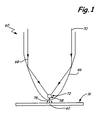
- An example of a parabolic planar waveguide is shown in FIG. 1 .
- Edge 66 of waveguide 60 is substantially parabolic in shape. If the refractive indices of material exterior to edge 66 are less than the indices of material of waveguide 60, waveguide 60 acts as a solid immersion lens. Electromagnetic waves 68 and 70 traveling along the longitudinal axis of waveguide 60 will be deflected at boundary 66 toward focal point 72 as shown.
- Diffraction gratings or other means known in the art to couple external energy into waveguide 60 can be configured to minimize radiation traveling down the center of waveguide 60 and maximize the energy reflected from parabolic edge 66, thereby increasing the energy content of the longitudinal component of waves 68 and 70 impinging on the focal point.
- NFTs Near field transducers
- the dimensions of the spot concentrated at focal point 72 of waveguide 60 are diffraction limited and are not sufficient for the sub-100 nm dimensions required for high areal density HAMR recording media.
- Near field transducers such as metallic pins, sphere/pin, or disc/pin combinations are required to focus the energy to acceptable sub-100 nm spot sizes.
- Near field transducer 58 in FIG. 1 is an example of a disc/pin combination NFT.
- NFT 58 is positioned at focal point 72 of waveguide 60 where it can couple with incident waves 68 and 70 to generate surface plasmons.
- the fields generated by the surface plasmons on the NFT also interact with recording medium 16 and transfer electromagnetic energy into the medium as shown by arrows 78 that heat a small region 62 of recording medium 16.
- NFT 58 includes head 80, pin (sometimes referred to as "peg") 82 and pin tip 84.
- NFT 58 may be made of gold or other suitable materials known in the art such as silver or aluminum.
- Head 80 on NFT is generally disc-shaped, and is generally larger than pin 82. Head 80 also may have a greater thickness than pin 82.
- NFT 58 is shaped in a manner that can efficiently capture the optical energy and transfer that energy efficiently to the recording medium.
- Pin tip 84 ensures that the energy transferred to the medium remains confined to an area that is defined by the cross section of the pin.
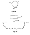
- Traditional transducers have pins with rectangular cross sections as shown in FIG. 2A . Transducers such as that shown in FIG. 2A are sometimes termed lollipop transducers.
- FIG. 2B A schematic ABS view of an optical transducer with a pin with a rectangular cross section is shown in FIG. 2B wherein write pole 36 is down-track of pin end 84 and return pole 38. It is desired to move the optical/thermal spot generated by pin end 84 closer to write pole 36 to achieve improved recording performance.
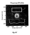
- the calculated optical field intensity distributions from optical modeling showing the temperature distribution in recording medium 16 resulting from laser light from NFT 58 with rectangular pin 82 is shown in FIG. 2C . Since the excitation laser light is incident on head 80 on the up-track side of NFT 58, optical/thermal spot 62 under rectangular pin tip 84 is closer to return pole 38 in the up-track direction and farther away from the write pole making thermal and magnetic alignment difficult. Pin 82 could be moved closer to write pole 36 but the resonant characteristics and thermal management during writing would be altered. In addition, producing pins with extremely small dimensions is challenging.
- FIG. 3A is a schematic ABS view of an optical transducer with pin 92, write pole 36, and return pole 38.
- Pin 92 is disposed between write pole 36 and return pole 38.
- Pin tip 94 is trapezoidal in shape, comprising first pin edge 96 and second pin edge 98.
- First pin edge 96 is smaller than second pin edge 98 and is closer to write pole 36 than second pin edge 98.
- the optical transducer is a lollipop transducer.
- first pin edge 96 is smaller in length than second pin edge 98, a higher charge density distribution will collect at first pin edge 96 because of the lightning rod effect of conductive materials.
- the lightning rod effect is a natural phenomenon that occurs for any sharp geometrical feature (comer or edge) of a conductive material. Quasi-electrostatic "crowding" of electric field lines at sharp geometrical features results in significant field enhancement. This effect occurs as long as the effective curvature of the feature is much smaller than the wavelength of interest.
- first pin edge 96 is a sharp geometrical feature of pin 92, and because first pin edge 96 is located closer to write pole 36 than second pin edge 98, the asymmetry of the optical near field will be such that the maximum in the temperature profile of the thermal spot will be moved closer to write pole 36 and coincide with the magnetic field distribution more efficiently as compared to more conventional HAMR systems.
- FIG. 3B shows essentially the same structure as FIG. 3A , only pin 93 is oriented 180° from its position in FIG. 3A . Second pin edge 98 is now closer to write pole 36 than first pin edge 96. This orientation of pin 82 may be applicable for certain HAMR design criteria.
- FIG. 3C is a schematic ABS view of another exemplary configuration of an optical transducer, which does not form part of the present invention, with pin 95, write pole 36, and return pole 38.
- FIG 3C is essentially the same structure as FIG. 3A , only pin 95 now has straight pin edge 96' and curved leading edge 98', wherein the pin cross section at pin tip 94' is a concave trapezoid. Curved edge 98' can improve HAMR thermal and magnetic performance by focusing the thermal spot such that the hottest part of the thermal profile is moved closer to write pole 36.
- optical NFT 58 with pin 94 shown in FIG. 3A has been evaluated by optical modeling of NFT recording on magnetic media.
- a gold lollipop NFT with a pin with trapezoidal cross section was integrated in a recording head with a solid immersion mirror (SIM) to focus waveguide light into the NFT.
- the waveguide comprised a 125 nm Ta 2 O 5 core with alumina cladding.
- the NFT was placed in the cladding 10 nm away from the waveguide core.
- the magnetic medium disc comprised a 2.5 nm thick overcoat, 10 nm thick magnetic recording layer, and a 7.5 nm thick thermal barrier coating deposited on a glass substrate.
- the recording head had a 2.5 nm overcoat and the fly height was assumed to be 2.5 nm.
- the laser light had a wavelength of 920 nm.
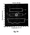
- the calculated optical field intensity distributions showing the temperature distribution in recording medium 16 are shown in FIG. 4 , which likewise does not form part of the present invention.
- spot 62 under trapezoidal pin 94 has a distinct trapezoidal shape with a trailing edge noticeably closer to write pole 36 and a leading edge at the leading edge of pin 94.
- the temperature profile of the heated spot is shown as dotted line 62.
- the trapezoidal shape of pin cross section 94 has clearly moved the heated spot closer to write pole 36.
- the distance from the hottest part of the spot to the write pole in FIG. 4 is about 50 nm.
- a coupled nanorod comprises a pair of rod-like structures proximate each other, such that, when illuminated with electromagnetic energy of a proper wavelength, will resonate and generate an intense optical spot at the end of the CNR located between the ends of both rods.
- An example of a vertical cross section of a CNR is shown in FIG. 5A .
- CNR 114 comprises rods 116, 116', 118, and 118' separated by gap 120.
- CNR 114 When acting as a NFT in a HAMR transducer, CNR 114 is placed at a focal point of a waveguide such as focal point 58 in FIG. 3 .
- CNR 114 resonates and surface plasmons on ends 117 and 119 of rods 116, 116', 118 and 118' respectively, heat recording media proximate the ABS 56.
- CNR 114 is shown in FIG. 5A comprising 4 nanorods, CNR structures can be constructed of two or more nanorods as necessary.
- CNR NFT assemblies are typically thin film structures made of gold, silver, aluminum, or other materials known in the art.
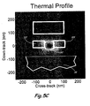
- FIG. 5B A schematic ABS view of CNR 114 is shown in FIG. 5B wherein write pole 36 is down-track of ends 117 and 119 of CNR 114 and return pole 38. It is critical to move the optical/thermal spot closer to write pole 36 to achieve improved recording performance.
- FIG. 5C A calculated thermal profile resulting from optical modeling showing the temperature distribution in recording media 16 from laser light from CNR 114 with rectangular ends 117 and 119 is shown in FIG. 5C .
- Optical/thermal spot 62 is closer to return pole 38 in the up track direction and farther away from writer pole 36 making thermal and magnetic alignment difficult. As discussed earlier, the thermal asymmetry results from the excitation laser light impinging on the up track side of CNR 114.
- FIG. 6A is a schematic ABS view of CNR 114 showing asymmetric nanorod ends 117 and 119, write pole 36, and return pole 38.
- First and second asymmetric nanorod tips 117 and 119 include first angled edge 126, second angled edge 128, and opposite edges 130 and 132.
- First angled edge 126 and second angled edge 128 are angled such that first and second nanorod tips 117 and 119 gradually grow farther apart away from pole 36.
- Opposite edges 130 and 132 are not angled.
- edges 131 and 133 are also angled to create trapezoidal cross sections.
- Other asymmetrical cross sections of nanorods 116 and 118, not shown, are also included in this invention.
- the NFT performance of CNR 114 with an asymmetrical gap has been evaluated by optical modeling of NFT recording on magnetic media.
- a coupled gold nanorod NFT was integrated in a recording head with a solid immersion mirror (SIM) to focus waveguide light into the NFT.
- the waveguide comprised a 125 nm Ta 2 O 5 core with alumina cladding.
- the NFT was placed in the cladding 10 nm away from the waveguide core.
- the magnetic medium disc comprised a 2.5 nm thick overcoat, 10 nm thick magnetic recording layer, and a 7.5 nm thick thermal barrier coating deposited on a glass substrate.
- the recording head had a 2.5 nm overcoat and the fly height was assumed to be 2.5 nm.
- the laser light had a wavelength of 920 nm.
- the cross-track and down-track intensity distributions are shown in FIG. 7B .
- the cross track intensity distribution as shown by the dotted line, is symmetric about the center.
- the non-uniform field distribution in the gap is clearly evident in FIG. 7A as compared to the field distribution in the case of a rectangular gap shown in FIG. 5C .
- the distance from the hottest part of the spot to the write pole in FIG. 7A is about 60 nm.
- the down-track intensity distribution in FIG. 7B shows a definite peak shift toward the writer pole as indicated by arrows DT.
- the full width at half maximum (FWHM) of the cross-track profile was 35 nm. FWHM decreased from 45 nm to 25 nm as W2 decreased from 35 nm to 15 nm respectively.
- the down-track optical gradient increased when the spot size decreased with a narrower gap. This will benefit HAMR recording.
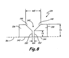
- CNR 134 comprises nanorods 136 and 138 with nanorod ends 142 and 144.
- Gap 140 with sides 146 and 148 is wide at the top and narrows to sides 150 and 152 at the bottom proximate the ABS. Plasmon loss in the narrow gap is offset by the larger plasmon energy in the upper gap.
- An added advantage of a tapered gap is that improved impedance matching between the exitation source (preferably a waveguide) and the NFT is possible by the design variable offered by the variable gap.
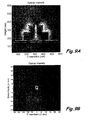
- FIG. 9A The optical intensity of a vertical cross section of CNR 114 ( FIG 5A ) is shown in FIG 9A .
- FIG. 9B shows the optical intensity distribution at the ABS from CNR 114.
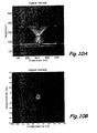
- the optical intensity of a vertical cross section of CNR 134 with the tapered gap ( FIG 8 ) is shown in FIG 10A .
- FIGS. 10B shows the optical intensity distribution at the ABS from CNR 134.
- the energy of CNR 134 is distinctly confined to the gap in FIGS. 10A and 10B .
- Both spots at the ABS in FIGS. 9B and 10B are similar in size, however, the peak intensity is more than doubled when a tapered entrance is used.
- the thickness of the NFT can be increased by as much as a few hundred nanometers without affecting writing performance.
- the asymmetric pins and rods also cause the shape and size of the spots to be more efficient.
- the increased gold thickness aids in dissipating heat energy thereby reducing the NFT temperature.
Landscapes
- Physics & Mathematics (AREA)
- Electromagnetism (AREA)
- Engineering & Computer Science (AREA)
- Manufacturing & Machinery (AREA)
- Recording Or Reproducing By Magnetic Means (AREA)
- Magnetic Heads (AREA)
- Optical Head (AREA)
Applications Claiming Priority (1)
| Application Number | Priority Date | Filing Date | Title |
|---|---|---|---|
| US12/785,003 US8385159B2 (en) | 2010-05-21 | 2010-05-21 | Near field transducer with shaped energy radiating end |
Publications (2)
| Publication Number | Publication Date |
|---|---|
| EP2388781A1 EP2388781A1 (en) | 2011-11-23 |
| EP2388781B1 true EP2388781B1 (en) | 2015-01-28 |
Family
ID=44117870
Family Applications (1)
| Application Number | Title | Priority Date | Filing Date |
|---|---|---|---|
| EP11167004.8A Not-in-force EP2388781B1 (en) | 2010-05-21 | 2011-05-20 | Near field transducer with shaped energy radiating end |
Country Status (4)
| Country | Link |
|---|---|
| US (1) | US8385159B2 (enExample) |
| EP (1) | EP2388781B1 (enExample) |
| JP (1) | JP5702224B2 (enExample) |
| CN (1) | CN102324238B (enExample) |
Cited By (1)
| Publication number | Priority date | Publication date | Assignee | Title |
|---|---|---|---|---|
| US9123374B1 (en) | 2015-02-12 | 2015-09-01 | Western Digital (Fremont), Llc | Heat assisted magnetic recording writer having an integrated polarization rotation plate |
Families Citing this family (33)
| Publication number | Priority date | Publication date | Assignee | Title |
|---|---|---|---|---|
| US9495996B2 (en) * | 2007-06-29 | 2016-11-15 | Seagate Technology, Llc | Writer with increased write field |
| US8248891B2 (en) * | 2008-11-18 | 2012-08-21 | Seagate Technology Llc | Near-field transducers for focusing light |
| US8416530B2 (en) * | 2009-10-20 | 2013-04-09 | Seagate Technology Llc | Write head with bevel structure and reverse NFT for HAMR |
| US8427925B2 (en) | 2010-02-23 | 2013-04-23 | Seagate Technology Llc | HAMR NFT materials with improved thermal stability |
| US9224416B2 (en) | 2012-04-24 | 2015-12-29 | Seagate Technology Llc | Near field transducers including nitride materials |
| US9251837B2 (en) | 2012-04-25 | 2016-02-02 | Seagate Technology Llc | HAMR NFT materials with improved thermal stability |
| US8649245B2 (en) * | 2010-03-29 | 2014-02-11 | Seagate Technology Llc | Direct waveguide light delivery to NFT for heat assisted magnetic recording |
| KR20110110941A (ko) * | 2010-04-02 | 2011-10-10 | 삼성전자주식회사 | 하드디스크 드라이브 |
| US8773959B2 (en) | 2010-05-21 | 2014-07-08 | Seagate Technology Llc | Near field transducer with shaped energy radiating end |
| US8351307B1 (en) | 2010-06-04 | 2013-01-08 | Western Digital (Fremont), Llc | Trailing edge optimized near field transducer having non-rectangular pin cross section |
| US8320219B1 (en) * | 2010-06-15 | 2012-11-27 | Western Digital (Fremont), Llc | Trailing edge optimized near field transducer |
| US8773956B1 (en) * | 2011-12-06 | 2014-07-08 | Western Digital (Fremont), Llc | Bi-layer NFT-core spacer for EAMR system and method of making the same |
| US8576672B1 (en) | 2012-05-25 | 2013-11-05 | Seagate Technology Llc | Heat sink layer |
| US8945731B2 (en) * | 2012-06-29 | 2015-02-03 | Seagate Technology Llc | Interlayer for device including NFT and cladding layers |
| US9385089B2 (en) | 2013-01-30 | 2016-07-05 | Seagate Technology Llc | Alignment mark recovery with reduced topography |
| US9343089B2 (en) * | 2013-03-08 | 2016-05-17 | Seagate Technology Llc | Nanoimprint lithography for thin film heads |
| US9135942B2 (en) | 2013-05-28 | 2015-09-15 | HGST Netherlands B.V. | Heat assisted magnetic recording head having wider heat sink and pole |
| US8810947B1 (en) | 2013-05-30 | 2014-08-19 | HGST Netherlands B.V. | Recessing a near field transducer in a heat-assisted magnetic recording head |
| US9245573B2 (en) | 2013-06-24 | 2016-01-26 | Seagate Technology Llc | Methods of forming materials for at least a portion of a NFT and NFTs formed using the same |
| US9502070B2 (en) | 2013-06-24 | 2016-11-22 | Seagate Technology Llc | Materials for near field transducers, near field tranducers containing same, and methods of forming |
| US8976634B2 (en) * | 2013-06-24 | 2015-03-10 | Seagate Technology Llc | Devices including at least one intermixing layer |
| US9129626B2 (en) | 2013-10-24 | 2015-09-08 | Seagate Technology Llc | Near-field transducer with rounded or obtuse corners |
| US20150132503A1 (en) * | 2013-11-13 | 2015-05-14 | Seagate Technology Llc | Methods of forming near field transducers |
| US9697856B2 (en) | 2013-12-06 | 2017-07-04 | Seagate Techology LLC | Methods of forming near field transducers and near field transducers formed thereby |
| US9570098B2 (en) | 2013-12-06 | 2017-02-14 | Seagate Technology Llc | Methods of forming near field transducers and near field transducers formed thereby |
| US8988827B1 (en) | 2014-01-17 | 2015-03-24 | HGST Netherlands B.V. | Surface diffusion inhibitor for HAMR NFT |
| JP6455875B2 (ja) * | 2014-09-30 | 2019-01-23 | 株式会社イノバステラ | 近接場光デバイス及びそれを用いた磁気ヘッド |
| US9449626B2 (en) * | 2014-11-07 | 2016-09-20 | Seagate Technology Llc | Structure positioned between magnetic pole and near-field transducer |
| US9822444B2 (en) | 2014-11-11 | 2017-11-21 | Seagate Technology Llc | Near-field transducer having secondary atom higher concentration at bottom of the peg |
| WO2016077197A1 (en) | 2014-11-12 | 2016-05-19 | Seagate Technology Llc | Devices including a near field transducer (nft) with nanoparticles |
| US10204646B2 (en) | 2016-05-04 | 2019-02-12 | Western Digital Technologies, Inc. | Near-field transducer with adjacent high-refractive index material layer |
| US11164600B1 (en) | 2016-08-26 | 2021-11-02 | Seagate Technology Llc | Methods of forming materials |
| US12013285B2 (en) | 2020-04-17 | 2024-06-18 | University of Pittsburgh—of the Commonwealth System of Higher Education | High temperature near-field probe for sensing and energy harvesting applications based upon thermal emission |
Citations (1)
| Publication number | Priority date | Publication date | Assignee | Title |
|---|---|---|---|---|
| US20080158709A1 (en) * | 2006-12-28 | 2008-07-03 | Tdk Corporation | Thermally assisted magnetic head, head gimbal assembly, and hard disk drive |
Family Cites Families (16)
| Publication number | Priority date | Publication date | Assignee | Title |
|---|---|---|---|---|
| US7412143B2 (en) | 2002-06-28 | 2008-08-12 | Seagate Technology Llc | Heat assisted magnetic recording with heat profile shaping |
| US6795630B2 (en) | 2002-06-28 | 2004-09-21 | Seagate Technology Llc | Apparatus and method for producing a small spot of optical energy |
| US7266268B2 (en) * | 2003-09-05 | 2007-09-04 | Seagate Technology Llc | Diffraction grating |
| US7155732B2 (en) * | 2003-09-05 | 2006-12-26 | Seagate Technology Llc | Heat assisted magnetic recording head and method |
| US7330404B2 (en) * | 2003-10-10 | 2008-02-12 | Seagate Technology Llc | Near-field optical transducers for thermal assisted magnetic and optical data storage |
| US7272079B2 (en) | 2004-06-23 | 2007-09-18 | Seagate Technology Llc | Transducer for heat assisted magnetic recording |
| JP4400579B2 (ja) * | 2006-01-30 | 2010-01-20 | Tdk株式会社 | 台形端を有する近接場光発生部を備えた薄膜磁気ヘッド |
| JP2008059645A (ja) * | 2006-08-30 | 2008-03-13 | Hitachi Ltd | 記録用ヘッド |
| US7440660B1 (en) * | 2007-10-16 | 2008-10-21 | Seagate Technology Llc | Transducer for heat assisted magnetic recording |
| US7706654B2 (en) * | 2007-11-05 | 2010-04-27 | Seagate Technology Llc | Integrated device for heat assisted magnetic recording |
| JP4518158B2 (ja) * | 2008-02-08 | 2010-08-04 | Tdk株式会社 | 熱アシスト磁気ヘッド、ヘッドジンバルアセンブリ、及びハードディスク装置 |
| US8000178B2 (en) * | 2008-10-29 | 2011-08-16 | Tdk Corporation | Near-field light generating element utilizing surface plasmon |
| US8248891B2 (en) * | 2008-11-18 | 2012-08-21 | Seagate Technology Llc | Near-field transducers for focusing light |
| US8111485B2 (en) * | 2008-11-19 | 2012-02-07 | Seagate Technology Llc | Arm mounted shock sensor and flexible circuit routing |
| US8416530B2 (en) * | 2009-10-20 | 2013-04-09 | Seagate Technology Llc | Write head with bevel structure and reverse NFT for HAMR |
| US8649245B2 (en) * | 2010-03-29 | 2014-02-11 | Seagate Technology Llc | Direct waveguide light delivery to NFT for heat assisted magnetic recording |
-
2010
- 2010-05-21 US US12/785,003 patent/US8385159B2/en not_active Expired - Fee Related
-
2011
- 2011-05-20 EP EP11167004.8A patent/EP2388781B1/en not_active Not-in-force
- 2011-05-20 JP JP2011113281A patent/JP5702224B2/ja not_active Expired - Fee Related
- 2011-05-20 CN CN201110195276.6A patent/CN102324238B/zh active Active
Patent Citations (1)
| Publication number | Priority date | Publication date | Assignee | Title |
|---|---|---|---|---|
| US20080158709A1 (en) * | 2006-12-28 | 2008-07-03 | Tdk Corporation | Thermally assisted magnetic head, head gimbal assembly, and hard disk drive |
Cited By (1)
| Publication number | Priority date | Publication date | Assignee | Title |
|---|---|---|---|---|
| US9123374B1 (en) | 2015-02-12 | 2015-09-01 | Western Digital (Fremont), Llc | Heat assisted magnetic recording writer having an integrated polarization rotation plate |
Also Published As
| Publication number | Publication date |
|---|---|
| EP2388781A1 (en) | 2011-11-23 |
| CN102324238B (zh) | 2014-07-16 |
| US20110286127A1 (en) | 2011-11-24 |
| JP2011248991A (ja) | 2011-12-08 |
| JP5702224B2 (ja) | 2015-04-15 |
| CN102324238A (zh) | 2012-01-18 |
| US8385159B2 (en) | 2013-02-26 |
Similar Documents
| Publication | Publication Date | Title |
|---|---|---|
| EP2388781B1 (en) | Near field transducer with shaped energy radiating end | |
| US8773959B2 (en) | Near field transducer with shaped energy radiating end | |
| US8649245B2 (en) | Direct waveguide light delivery to NFT for heat assisted magnetic recording | |
| JP5774497B2 (ja) | 熱に補助される磁気記録のための記録ヘッド | |
| US9355661B2 (en) | Integrated head for heat assisted magnetic recording | |
| US8351305B2 (en) | Notched pole design for HAMR recording | |
| JP4899134B2 (ja) | 熱アシスト磁気記録用トランスデューサ | |
| US8451705B2 (en) | Plasmonic transducer having two metal elements with a gap disposed therebetween | |
| US7155732B2 (en) | Heat assisted magnetic recording head and method | |
| US8711662B2 (en) | Near-field transducers for focusing light | |
| US6714370B2 (en) | Write head and method for recording information on a data storage medium | |
| US7649677B2 (en) | Multi-ridged subwavelength aperture for optical transmission and thermally assisted magnetic recording | |
| US8416530B2 (en) | Write head with bevel structure and reverse NFT for HAMR | |
| EP2631908B1 (en) | Plasmonic Funnel for Focused Optical Delivery | |
| US9449626B2 (en) | Structure positioned between magnetic pole and near-field transducer | |
| US7652954B2 (en) | Thermally assisted recording head with magnetic pole integrated into optical aperture for dual gradient recording | |
| US11380354B2 (en) | Heat-assisted magnetic recording head having near-field transducer with sunken plasmonic plate | |
| KR100821744B1 (ko) | 회절 격자 | |
| US12380918B1 (en) | Energy-assisted recording head with C-shaped delivery waveguide core | |
| WO2005034093A1 (en) | Heat assisted magnetic recording head and method |
Legal Events
| Date | Code | Title | Description |
|---|---|---|---|
| 17P | Request for examination filed |
Effective date: 20110620 |
|
| AK | Designated contracting states |
Kind code of ref document: A1 Designated state(s): AL AT BE BG CH CY CZ DE DK EE ES FI FR GB GR HR HU IE IS IT LI LT LU LV MC MK MT NL NO PL PT RO RS SE SI SK SM TR |
|
| AX | Request for extension of the european patent |
Extension state: BA ME |
|
| PUAI | Public reference made under article 153(3) epc to a published international application that has entered the european phase |
Free format text: ORIGINAL CODE: 0009012 |
|
| RIN1 | Information on inventor provided before grant (corrected) |
Inventor name: ZHAO, YONGJUN Inventor name: CHALLENER, WILLIAM A. Inventor name: GAO, KAIZHONG Inventor name: JIN, XUHUI |
|
| RAP1 | Party data changed (applicant data changed or rights of an application transferred) |
Owner name: SEAGATE TECHNOLOGY LLC |
|
| 17Q | First examination report despatched |
Effective date: 20120615 |
|
| GRAP | Despatch of communication of intention to grant a patent |
Free format text: ORIGINAL CODE: EPIDOSNIGR1 |
|
| INTG | Intention to grant announced |
Effective date: 20140812 |
|
| GRAS | Grant fee paid |
Free format text: ORIGINAL CODE: EPIDOSNIGR3 |
|
| GRAA | (expected) grant |
Free format text: ORIGINAL CODE: 0009210 |
|
| AK | Designated contracting states |
Kind code of ref document: B1 Designated state(s): AL AT BE BG CH CY CZ DE DK EE ES FI FR GB GR HR HU IE IS IT LI LT LU LV MC MK MT NL NO PL PT RO RS SE SI SK SM TR |
|
| REG | Reference to a national code |
Ref country code: GB Ref legal event code: FG4D |
|
| REG | Reference to a national code |
Ref country code: CH Ref legal event code: EP |
|
| REG | Reference to a national code |
Ref country code: IE Ref legal event code: FG4D |
|
| REG | Reference to a national code |
Ref country code: DE Ref legal event code: R096 Ref document number: 602011013466 Country of ref document: DE Effective date: 20150312 |
|
| REG | Reference to a national code |
Ref country code: AT Ref legal event code: REF Ref document number: 708537 Country of ref document: AT Kind code of ref document: T Effective date: 20150315 |
|
| REG | Reference to a national code |
Ref country code: AT Ref legal event code: MK05 Ref document number: 708537 Country of ref document: AT Kind code of ref document: T Effective date: 20150128 |
|
| REG | Reference to a national code |
Ref country code: NL Ref legal event code: VDEP Effective date: 20150128 |
|
| REG | Reference to a national code |
Ref country code: LT Ref legal event code: MG4D |
|
| PG25 | Lapsed in a contracting state [announced via postgrant information from national office to epo] |
Ref country code: SE Free format text: LAPSE BECAUSE OF FAILURE TO SUBMIT A TRANSLATION OF THE DESCRIPTION OR TO PAY THE FEE WITHIN THE PRESCRIBED TIME-LIMIT Effective date: 20150128 Ref country code: BG Free format text: LAPSE BECAUSE OF FAILURE TO SUBMIT A TRANSLATION OF THE DESCRIPTION OR TO PAY THE FEE WITHIN THE PRESCRIBED TIME-LIMIT Effective date: 20150428 Ref country code: LT Free format text: LAPSE BECAUSE OF FAILURE TO SUBMIT A TRANSLATION OF THE DESCRIPTION OR TO PAY THE FEE WITHIN THE PRESCRIBED TIME-LIMIT Effective date: 20150128 Ref country code: HR Free format text: LAPSE BECAUSE OF FAILURE TO SUBMIT A TRANSLATION OF THE DESCRIPTION OR TO PAY THE FEE WITHIN THE PRESCRIBED TIME-LIMIT Effective date: 20150128 Ref country code: NO Free format text: LAPSE BECAUSE OF FAILURE TO SUBMIT A TRANSLATION OF THE DESCRIPTION OR TO PAY THE FEE WITHIN THE PRESCRIBED TIME-LIMIT Effective date: 20150428 Ref country code: FI Free format text: LAPSE BECAUSE OF FAILURE TO SUBMIT A TRANSLATION OF THE DESCRIPTION OR TO PAY THE FEE WITHIN THE PRESCRIBED TIME-LIMIT Effective date: 20150128 Ref country code: ES Free format text: LAPSE BECAUSE OF FAILURE TO SUBMIT A TRANSLATION OF THE DESCRIPTION OR TO PAY THE FEE WITHIN THE PRESCRIBED TIME-LIMIT Effective date: 20150128 |
|
| PG25 | Lapsed in a contracting state [announced via postgrant information from national office to epo] |
Ref country code: RS Free format text: LAPSE BECAUSE OF FAILURE TO SUBMIT A TRANSLATION OF THE DESCRIPTION OR TO PAY THE FEE WITHIN THE PRESCRIBED TIME-LIMIT Effective date: 20150128 Ref country code: LV Free format text: LAPSE BECAUSE OF FAILURE TO SUBMIT A TRANSLATION OF THE DESCRIPTION OR TO PAY THE FEE WITHIN THE PRESCRIBED TIME-LIMIT Effective date: 20150128 Ref country code: GR Free format text: LAPSE BECAUSE OF FAILURE TO SUBMIT A TRANSLATION OF THE DESCRIPTION OR TO PAY THE FEE WITHIN THE PRESCRIBED TIME-LIMIT Effective date: 20150429 Ref country code: AT Free format text: LAPSE BECAUSE OF FAILURE TO SUBMIT A TRANSLATION OF THE DESCRIPTION OR TO PAY THE FEE WITHIN THE PRESCRIBED TIME-LIMIT Effective date: 20150128 Ref country code: IS Free format text: LAPSE BECAUSE OF FAILURE TO SUBMIT A TRANSLATION OF THE DESCRIPTION OR TO PAY THE FEE WITHIN THE PRESCRIBED TIME-LIMIT Effective date: 20150528 Ref country code: PL Free format text: LAPSE BECAUSE OF FAILURE TO SUBMIT A TRANSLATION OF THE DESCRIPTION OR TO PAY THE FEE WITHIN THE PRESCRIBED TIME-LIMIT Effective date: 20150128 Ref country code: NL Free format text: LAPSE BECAUSE OF FAILURE TO SUBMIT A TRANSLATION OF THE DESCRIPTION OR TO PAY THE FEE WITHIN THE PRESCRIBED TIME-LIMIT Effective date: 20150128 |
|
| REG | Reference to a national code |
Ref country code: DE Ref legal event code: R097 Ref document number: 602011013466 Country of ref document: DE |
|
| PG25 | Lapsed in a contracting state [announced via postgrant information from national office to epo] |
Ref country code: SK Free format text: LAPSE BECAUSE OF FAILURE TO SUBMIT A TRANSLATION OF THE DESCRIPTION OR TO PAY THE FEE WITHIN THE PRESCRIBED TIME-LIMIT Effective date: 20150128 Ref country code: CZ Free format text: LAPSE BECAUSE OF FAILURE TO SUBMIT A TRANSLATION OF THE DESCRIPTION OR TO PAY THE FEE WITHIN THE PRESCRIBED TIME-LIMIT Effective date: 20150128 Ref country code: RO Free format text: LAPSE BECAUSE OF FAILURE TO SUBMIT A TRANSLATION OF THE DESCRIPTION OR TO PAY THE FEE WITHIN THE PRESCRIBED TIME-LIMIT Effective date: 20150128 Ref country code: DK Free format text: LAPSE BECAUSE OF FAILURE TO SUBMIT A TRANSLATION OF THE DESCRIPTION OR TO PAY THE FEE WITHIN THE PRESCRIBED TIME-LIMIT Effective date: 20150128 Ref country code: EE Free format text: LAPSE BECAUSE OF FAILURE TO SUBMIT A TRANSLATION OF THE DESCRIPTION OR TO PAY THE FEE WITHIN THE PRESCRIBED TIME-LIMIT Effective date: 20150128 |
|
| PLBE | No opposition filed within time limit |
Free format text: ORIGINAL CODE: 0009261 |
|
| STAA | Information on the status of an ep patent application or granted ep patent |
Free format text: STATUS: NO OPPOSITION FILED WITHIN TIME LIMIT |
|
| PG25 | Lapsed in a contracting state [announced via postgrant information from national office to epo] |
Ref country code: IT Free format text: LAPSE BECAUSE OF FAILURE TO SUBMIT A TRANSLATION OF THE DESCRIPTION OR TO PAY THE FEE WITHIN THE PRESCRIBED TIME-LIMIT Effective date: 20150128 |
|
| REG | Reference to a national code |
Ref country code: CH Ref legal event code: PL |
|
| 26N | No opposition filed |
Effective date: 20151029 |
|
| PG25 | Lapsed in a contracting state [announced via postgrant information from national office to epo] |
Ref country code: MC Free format text: LAPSE BECAUSE OF FAILURE TO SUBMIT A TRANSLATION OF THE DESCRIPTION OR TO PAY THE FEE WITHIN THE PRESCRIBED TIME-LIMIT Effective date: 20150128 Ref country code: LI Free format text: LAPSE BECAUSE OF NON-PAYMENT OF DUE FEES Effective date: 20150531 Ref country code: CH Free format text: LAPSE BECAUSE OF NON-PAYMENT OF DUE FEES Effective date: 20150531 Ref country code: LU Free format text: LAPSE BECAUSE OF FAILURE TO SUBMIT A TRANSLATION OF THE DESCRIPTION OR TO PAY THE FEE WITHIN THE PRESCRIBED TIME-LIMIT Effective date: 20150520 |
|
| REG | Reference to a national code |
Ref country code: IE Ref legal event code: MM4A |
|
| PG25 | Lapsed in a contracting state [announced via postgrant information from national office to epo] |
Ref country code: SI Free format text: LAPSE BECAUSE OF FAILURE TO SUBMIT A TRANSLATION OF THE DESCRIPTION OR TO PAY THE FEE WITHIN THE PRESCRIBED TIME-LIMIT Effective date: 20150128 |
|
| REG | Reference to a national code |
Ref country code: FR Ref legal event code: PLFP Year of fee payment: 6 |
|
| PG25 | Lapsed in a contracting state [announced via postgrant information from national office to epo] |
Ref country code: IE Free format text: LAPSE BECAUSE OF NON-PAYMENT OF DUE FEES Effective date: 20150520 |
|
| PG25 | Lapsed in a contracting state [announced via postgrant information from national office to epo] |
Ref country code: BE Free format text: LAPSE BECAUSE OF FAILURE TO SUBMIT A TRANSLATION OF THE DESCRIPTION OR TO PAY THE FEE WITHIN THE PRESCRIBED TIME-LIMIT Effective date: 20150128 |
|
| PGFP | Annual fee paid to national office [announced via postgrant information from national office to epo] |
Ref country code: DE Payment date: 20160518 Year of fee payment: 6 |
|
| PGFP | Annual fee paid to national office [announced via postgrant information from national office to epo] |
Ref country code: FR Payment date: 20160412 Year of fee payment: 6 |
|
| PG25 | Lapsed in a contracting state [announced via postgrant information from national office to epo] |
Ref country code: MT Free format text: LAPSE BECAUSE OF FAILURE TO SUBMIT A TRANSLATION OF THE DESCRIPTION OR TO PAY THE FEE WITHIN THE PRESCRIBED TIME-LIMIT Effective date: 20150128 |
|
| PG25 | Lapsed in a contracting state [announced via postgrant information from national office to epo] |
Ref country code: SM Free format text: LAPSE BECAUSE OF FAILURE TO SUBMIT A TRANSLATION OF THE DESCRIPTION OR TO PAY THE FEE WITHIN THE PRESCRIBED TIME-LIMIT Effective date: 20150128 Ref country code: HU Free format text: LAPSE BECAUSE OF FAILURE TO SUBMIT A TRANSLATION OF THE DESCRIPTION OR TO PAY THE FEE WITHIN THE PRESCRIBED TIME-LIMIT; INVALID AB INITIO Effective date: 20110520 |
|
| PG25 | Lapsed in a contracting state [announced via postgrant information from national office to epo] |
Ref country code: CY Free format text: LAPSE BECAUSE OF FAILURE TO SUBMIT A TRANSLATION OF THE DESCRIPTION OR TO PAY THE FEE WITHIN THE PRESCRIBED TIME-LIMIT Effective date: 20150128 |
|
| PGFP | Annual fee paid to national office [announced via postgrant information from national office to epo] |
Ref country code: GB Payment date: 20170424 Year of fee payment: 7 |
|
| PG25 | Lapsed in a contracting state [announced via postgrant information from national office to epo] |
Ref country code: TR Free format text: LAPSE BECAUSE OF FAILURE TO SUBMIT A TRANSLATION OF THE DESCRIPTION OR TO PAY THE FEE WITHIN THE PRESCRIBED TIME-LIMIT Effective date: 20150128 |
|
| REG | Reference to a national code |
Ref country code: DE Ref legal event code: R119 Ref document number: 602011013466 Country of ref document: DE |
|
| REG | Reference to a national code |
Ref country code: FR Ref legal event code: ST Effective date: 20180131 |
|
| PG25 | Lapsed in a contracting state [announced via postgrant information from national office to epo] |
Ref country code: DE Free format text: LAPSE BECAUSE OF NON-PAYMENT OF DUE FEES Effective date: 20171201 |
|
| PG25 | Lapsed in a contracting state [announced via postgrant information from national office to epo] |
Ref country code: FR Free format text: LAPSE BECAUSE OF NON-PAYMENT OF DUE FEES Effective date: 20170531 |
|
| PG25 | Lapsed in a contracting state [announced via postgrant information from national office to epo] |
Ref country code: PT Free format text: LAPSE BECAUSE OF FAILURE TO SUBMIT A TRANSLATION OF THE DESCRIPTION OR TO PAY THE FEE WITHIN THE PRESCRIBED TIME-LIMIT Effective date: 20150128 Ref country code: MK Free format text: LAPSE BECAUSE OF FAILURE TO SUBMIT A TRANSLATION OF THE DESCRIPTION OR TO PAY THE FEE WITHIN THE PRESCRIBED TIME-LIMIT Effective date: 20150128 |
|
| PG25 | Lapsed in a contracting state [announced via postgrant information from national office to epo] |
Ref country code: AL Free format text: LAPSE BECAUSE OF FAILURE TO SUBMIT A TRANSLATION OF THE DESCRIPTION OR TO PAY THE FEE WITHIN THE PRESCRIBED TIME-LIMIT Effective date: 20150128 |
|
| GBPC | Gb: european patent ceased through non-payment of renewal fee |
Effective date: 20180520 |
|
| PG25 | Lapsed in a contracting state [announced via postgrant information from national office to epo] |
Ref country code: GB Free format text: LAPSE BECAUSE OF NON-PAYMENT OF DUE FEES Effective date: 20180520 |