EP2388570B2 - Adsorptive gas analyzer - Google Patents
Adsorptive gas analyzer Download PDFInfo
- Publication number
- EP2388570B2 EP2388570B2 EP11004047.4A EP11004047A EP2388570B2 EP 2388570 B2 EP2388570 B2 EP 2388570B2 EP 11004047 A EP11004047 A EP 11004047A EP 2388570 B2 EP2388570 B2 EP 2388570B2
- Authority
- EP
- European Patent Office
- Prior art keywords
- measurement cell
- negative pressure
- sample gas
- measurement
- flow rate
- Prior art date
- Legal status (The legal status is an assumption and is not a legal conclusion. Google has not performed a legal analysis and makes no representation as to the accuracy of the status listed.)
- Active
Links
Images
Classifications
-
- G—PHYSICS
- G01—MEASURING; TESTING
- G01N—INVESTIGATING OR ANALYSING MATERIALS BY DETERMINING THEIR CHEMICAL OR PHYSICAL PROPERTIES
- G01N21/00—Investigating or analysing materials by the use of optical means, i.e. using sub-millimetre waves, infrared, visible or ultraviolet light
- G01N21/17—Systems in which incident light is modified in accordance with the properties of the material investigated
- G01N21/25—Colour; Spectral properties, i.e. comparison of effect of material on the light at two or more different wavelengths or wavelength bands
- G01N21/31—Investigating relative effect of material at wavelengths characteristic of specific elements or molecules, e.g. atomic absorption spectrometry
- G01N21/35—Investigating relative effect of material at wavelengths characteristic of specific elements or molecules, e.g. atomic absorption spectrometry using infrared light
- G01N21/3504—Investigating relative effect of material at wavelengths characteristic of specific elements or molecules, e.g. atomic absorption spectrometry using infrared light for analysing gases, e.g. multi-gas analysis
-
- F—MECHANICAL ENGINEERING; LIGHTING; HEATING; WEAPONS; BLASTING
- F27—FURNACES; KILNS; OVENS; RETORTS
- F27D—DETAILS OR ACCESSORIES OF FURNACES, KILNS, OVENS OR RETORTS, IN SO FAR AS THEY ARE OF KINDS OCCURRING IN MORE THAN ONE KIND OF FURNACE
- F27D19/00—Arrangements of controlling devices
- F27D2019/0006—Monitoring the characteristics (composition, quantities, temperature, pressure) of at least one of the gases of the kiln atmosphere and using it as a controlling value
- F27D2019/0012—Monitoring the composition of the atmosphere or of one of their components
- F27D2019/0015—Monitoring the composition of the exhaust gases or of one of its components
-
- G—PHYSICS
- G01—MEASURING; TESTING
- G01N—INVESTIGATING OR ANALYSING MATERIALS BY DETERMINING THEIR CHEMICAL OR PHYSICAL PROPERTIES
- G01N1/00—Sampling; Preparing specimens for investigation
- G01N1/02—Devices for withdrawing samples
- G01N1/22—Devices for withdrawing samples in the gaseous state
- G01N1/2247—Sampling from a flowing stream of gas
- G01N1/2252—Sampling from a flowing stream of gas in a vehicle exhaust
-
- G—PHYSICS
- G01—MEASURING; TESTING
- G01N—INVESTIGATING OR ANALYSING MATERIALS BY DETERMINING THEIR CHEMICAL OR PHYSICAL PROPERTIES
- G01N21/00—Investigating or analysing materials by the use of optical means, i.e. using sub-millimetre waves, infrared, visible or ultraviolet light
- G01N21/17—Systems in which incident light is modified in accordance with the properties of the material investigated
- G01N21/25—Colour; Spectral properties, i.e. comparison of effect of material on the light at two or more different wavelengths or wavelength bands
- G01N21/31—Investigating relative effect of material at wavelengths characteristic of specific elements or molecules, e.g. atomic absorption spectrometry
- G01N21/35—Investigating relative effect of material at wavelengths characteristic of specific elements or molecules, e.g. atomic absorption spectrometry using infrared light
- G01N2021/3595—Investigating relative effect of material at wavelengths characteristic of specific elements or molecules, e.g. atomic absorption spectrometry using infrared light using FTIR
-
- G—PHYSICS
- G01—MEASURING; TESTING
- G01N—INVESTIGATING OR ANALYSING MATERIALS BY DETERMINING THEIR CHEMICAL OR PHYSICAL PROPERTIES
- G01N21/00—Investigating or analysing materials by the use of optical means, i.e. using sub-millimetre waves, infrared, visible or ultraviolet light
- G01N21/01—Arrangements or apparatus for facilitating the optical investigation
- G01N21/03—Cuvette constructions
- G01N21/031—Multipass arrangements
-
- G—PHYSICS
- G01—MEASURING; TESTING
- G01N—INVESTIGATING OR ANALYSING MATERIALS BY DETERMINING THEIR CHEMICAL OR PHYSICAL PROPERTIES
- G01N21/00—Investigating or analysing materials by the use of optical means, i.e. using sub-millimetre waves, infrared, visible or ultraviolet light
- G01N21/17—Systems in which incident light is modified in accordance with the properties of the material investigated
- G01N21/25—Colour; Spectral properties, i.e. comparison of effect of material on the light at two or more different wavelengths or wavelength bands
- G01N21/31—Investigating relative effect of material at wavelengths characteristic of specific elements or molecules, e.g. atomic absorption spectrometry
- G01N21/33—Investigating relative effect of material at wavelengths characteristic of specific elements or molecules, e.g. atomic absorption spectrometry using ultraviolet light
-
- G—PHYSICS
- G01—MEASURING; TESTING
- G01N—INVESTIGATING OR ANALYSING MATERIALS BY DETERMINING THEIR CHEMICAL OR PHYSICAL PROPERTIES
- G01N21/00—Investigating or analysing materials by the use of optical means, i.e. using sub-millimetre waves, infrared, visible or ultraviolet light
- G01N21/17—Systems in which incident light is modified in accordance with the properties of the material investigated
- G01N21/25—Colour; Spectral properties, i.e. comparison of effect of material on the light at two or more different wavelengths or wavelength bands
- G01N21/31—Investigating relative effect of material at wavelengths characteristic of specific elements or molecules, e.g. atomic absorption spectrometry
- G01N21/35—Investigating relative effect of material at wavelengths characteristic of specific elements or molecules, e.g. atomic absorption spectrometry using infrared light
- G01N21/359—Investigating relative effect of material at wavelengths characteristic of specific elements or molecules, e.g. atomic absorption spectrometry using infrared light using near infrared light
-
- G—PHYSICS
- G01—MEASURING; TESTING
- G01N—INVESTIGATING OR ANALYSING MATERIALS BY DETERMINING THEIR CHEMICAL OR PHYSICAL PROPERTIES
- G01N21/00—Investigating or analysing materials by the use of optical means, i.e. using sub-millimetre waves, infrared, visible or ultraviolet light
- G01N21/17—Systems in which incident light is modified in accordance with the properties of the material investigated
- G01N21/25—Colour; Spectral properties, i.e. comparison of effect of material on the light at two or more different wavelengths or wavelength bands
- G01N21/31—Investigating relative effect of material at wavelengths characteristic of specific elements or molecules, e.g. atomic absorption spectrometry
- G01N21/39—Investigating relative effect of material at wavelengths characteristic of specific elements or molecules, e.g. atomic absorption spectrometry using tunable lasers
-
- G—PHYSICS
- G01—MEASURING; TESTING
- G01N—INVESTIGATING OR ANALYSING MATERIALS BY DETERMINING THEIR CHEMICAL OR PHYSICAL PROPERTIES
- G01N2201/00—Features of devices classified in G01N21/00
- G01N2201/06—Illumination; Optics
- G01N2201/069—Supply of sources
- G01N2201/0696—Pulsed
- G01N2201/0697—Pulsed lasers
Definitions
- This invention relates to a gas analyzer that measures a concentration of a component of a gas having the adsorption such as an ammonia (NH 3 ) component or a hydrocarbon (HC) component contained in a sample gas such as an exhaust gas.
- a gas analyzer that measures a concentration of a component of a gas having the adsorption such as an ammonia (NH 3 ) component or a hydrocarbon (HC) component contained in a sample gas such as an exhaust gas.
- a conventional gas analyzer used for measuring a concentration of NH 3 introduces an exhaust gas emitted from an exhaust pipe of an automobile into a measurement cell by means of a sampling pipe and measures the concentration of NH 3 by the use of a light absorbance of NH 3 .
- a suction pump is arranged between the sampling pipe and the measurement cell to sample the exhaust gas and to introduce the sampled sample gas into the measurement cell.
- a pressure of inside of the sampling pipe fluctuates between a negative pressure and a positive pressure by the pressure of the exhaust gas emitted from the exhaust pipe (a tail pipe).
- a pressure of the exhaust gas emitted from the exhaust pipe a tail pipe.
- NH 3 easily attaches to the inner wall of the sampling pipe.
- the measurement of the concentration conducted in the measurement cell is a Fourier transform infrared spectroscopy (FTIR) or a Non-dispersive infrared analyzing method (NDIR).
- FTIR Fourier transform infrared spectroscopy
- NDIR Non-dispersive infrared analyzing method
- Patent document 1 Japan patent laid-open number 2001-159587
- a main object of this invention is to make it possible to measure the concentration of the adsorptive gas component having a polar characteristic such as NH 3 component or HC component with high accuracy even though the concentration is low and to improve the response speed of the concentration measurement
- the adsorptive gas analyzer in accordance with this invention is to measure a concentration of an adsorptive component having a polar character contained in a sample gas, and is characterized by comprising a body that has a measurement cell to measure the sample gas and an introduction port to introduce the sample gas into the measurement cell, a laser light irradiation part that irradiates the laser light on the measurement cell, a heating pipe that is connected to the introduction port and that applies heat to the sample gas introduced into the introduction port, a flow rate limit part that makes the sample gas at a negative pressure and that introduces the negative-pressurized heated sample gas into the body, and a negative pressure pump that is connected to the measurement cell, that keeps inside of the measurement cell at the negative pressure from a starting time of a sampling to an ending time of the measurement and that keeps a flow channel from a downstream side of the flow rate limit part to the measurement cell at the negative pressure from the starting time of the sampling to the ending time of the measurement
- the heating pipe and the flow rate limit part are arranged outside of the body and inside of the measurement cell and the flow channel from the downstream side of the flow rate limit part to the measurement cell are made at the negative pressure by means of the negative pressure pump, it is possible to enlarge the area at the negative pressure in the flow channel connected to the measurement cell, thereby enabling to reduce adsorption of the adsorptive gas component having the polar character such as NH 3 or HC.
- the flow rate limit part is arranged and the negative pressure is kept by the negative pressure pump from the starting time of the sampling to the ending time of the measurement, it is possible to prevent the downstream side of the flow rate limit part from being at a positive pressure due to a flowing pressure of the sample gas, thereby enabling to prevent attachment of the adsorptive gas component.
- the concentration of the adsorptive gas having a polar character such as the NH 3 component or the HC component is measured with high accuracy even though its concentration is low, and furthermore it is possible to improve the response speed of measuring the concentration.
- the negative pressurized sample gas is heated by the heating pipe, it is possible to prevent a dissolution loss of the adsorptive gas component associated with the due condensation in the pipe, thereby enabling to further improve the measurement accuracy and the response speed. Furthermore, if the absorption spectrum at an atmospheric pressure is monitored, it is known that the absorption peak is wide. Then if inside of the measurement cell is kept at the negative pressure, it is possible to obtain a sharper peak, thereby enabling to reduce an interference influence on the absorption peak by the adsorptive gas component
- the measurement cell is of a multiple reflection type. With this arrangement, it is possible to lengthen the optical length in the measurement cell so that the detected signal is increased, thereby enabling to improve the detecting sensitivity. Especially, it is effective for measuring the concentration of the gas of low concentration such as NH 3 contained in the sample gas. Since this invention irradiates the laser light, it is possible to elongate the optical length effectively if the cell of the multiple reflection type is used.
- the exhaust gas analyzer 100 in accordance with this embodiment is connected to, for example, an exhaust pipe (a tail pipe) of an automobile, and measures a concentration of NO, NO 2 , N 2 O and NH 3 contained in an exhaust gas as being a sample gas emitted from the exhaust pipe by the use of an absorptiometry.
- the exhaust gas analyzer 100 comprises, as shown in Fig. 1 , a body 2 to measure the sample gas, a flow rate control unit 3 that is arranged separately from the body 2 and that is mounted on the exhaust pipe of the automobile, and a heating pipe 4 that is connected to the body 2 and the flow rate control unit 3 and that introduces the exhaust gas introduced from the flow rate control unit 3 into the body 2.
- the body 2 and the flow rate control unit 3 are arranged at a different position respectively, and connected by only the heating pipe 4 without any additional casing that houses both the body 2 and the flow rate control unit 3.
- the body 2 comprises a measurement cell 21 of a multiple reflection type that measures the sample gas, a laser light irradiation part 22 that irradiates the laser light L1 having high linearity on the sample gas in the measurement cell 21 by introducing the laser light L1 from a light introducing window of the measurement cell 21, a light detecting part 23 that detects the transmitted laser light L2 coming from the measurement cell 21, and a negative pressure pump 24 that is connected to the measurement cell 21 and that makes inside of the measurement cell 21 at a negative pressure. Since the measurement cell 21 is of the multiple reflection type, it is possible to heighten the detection sensitivity even though the concentration of the measurement component is low.
- the negative pressure pump 24 keeps the inside of the measurement cell 21 at the negative pressure within a range, for example, between 1 kPa (at this pressure it becomes difficult to conduct the measurement because the gas concentration is too small) and 80 kPa (at this pressure interference with other gas component occurs easily because the peak is broad), and preferably keeps the inside of the measurement cell 21 at the negative pressure within a range between 20 kPa and 50 kPa that is a pressure range at which adsorption of NH 3 is difficult to occur, and the interference with other gas component does not occur with realizing a gas concentration that can be measured.
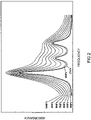
- a peak begins to form at less than or equal to 80 kPa and its peak is clearly expressed at less than or equal to 50 kPa.
- the body 2 has an introduction port 2P to which the heating pipe 4, to be described later, is connected and that is to introduce the exhaust gas flowing in the heating pipe 4 into the measurement cell 21.
- the introduction port 2P, the internal connecting pipe 25 and the measurement cell 21 are heated at, for example, 113 °C or 191 °C.
- the laser light irradiation part 22 comprises a laser light source 221 to irradiate the laser light L1, and a guide mechanism 222 comprising a reflection mirror to guide the light from the laser light source 221 to the measurement cell 21.
- an object as the adsorptive gas component is NH 3
- the laser light source 221 uses a tunable laser that irradiates the laser light having an infrared region wavelength such as a mid-infrared region or a near-infrared region where NH 3 has an absorption property or the laser light having an oscillation wavelength in an ultraviolet region, and uses, for example, a quantum cascade laser (QCL), a semiconductor laser such as a tunable semiconductor laser, a solid laser or a liquid laser.
- QCL quantum cascade laser
- the quantum cascade laser (QCL) as the laser light source 221.
- QCL quantum cascade laser
- a quantum cascade laser element oscillates the laser light by means of an electric current pulse having a certain interval. Since an oscillation frequency from the laser element depends on the temperature, the oscillation frequency repeats a scan in a narrow frequency range in terms of result
- the absorptionmetric method using the QCL uses an element whose oscillation central frequency is adjusted so as to fall the absorption peak position of a component as a target within this frequency range.
- a density of the adsorptive gas component such as NH 3 in the sample gas is small and its absorption peak becomes small in the negative-pressurized measurement cell 21, the sensitivity drops.
- the QCL having an oscillation wavelength (a pulse width is 500 nsec) in the near-infrared region is used, it is possible to make the absorption peak big. As a result, it is possible to measure the concentration of the adsorptive gas component without deteriorating the sensitivity under the negative pressure and to obtain a high speed response.
- the light detecting part 23 detects the transmitted laser light L2 from the measurement cell 21 after multiple reflection in the measurement cell 21, and it can be conceived to use, for example, an MCT (HgCdTe) detector 23 of a normal temperature operation type.
- a guide mechanism 232 comprising a reflection mirror to guide the transmitted laser light L2 to the light detector 231 is arranged between the MCT detector 231 and the measurement cell 21.
- the light intensity signal obtained by the light detector 231 is output to a calculation device, not shown in drawings. The light absorption of each component is calculated and then the concentration of each component is calculated by the calculation device.
- the flow rate control unit 3 is connected to the exhaust pipe of the automobile, and comprises a filter 31 to remove a dust in the exhaust gas emitted from the exhaust pipe and a flow rate limit part 32 to limit a flow rate of the exhaust gas passing the filter 31.
- the flow rate control unit 3 is mounted directly on an exhaust opening or on a position within 2 m from the exhaust opening through a piping. It is especially preferable that the flow rate control unit 3 is mounted on a position within 50 cm from the exhaust opening. With this arrangement, it is possible to make the exhaust gas from the exhaust pipe at the negative pressure in the upstream side at an early stage.
- the filter 31 comprises, for example, a cylindrical filter 31a that is arranged in the upstream side and that can be exchanged by a user, and, for example, a disk-shaped filter 31b that is arranged inside of the flow rate control unit 3 and in the downstream side and that can not be exchanged by a user.
- a critical flow orifice (CFO) is used as the flow rate limit part 32 to shorten a response time by lessening an area to contact the gas. Since the flow rate control unit 3 is a unit having the filter 31 and the critical flow orifice (CFO), it can be downsized.
- the flow rate limit part 32 comprises two critical flow orifices CFO1 and CFO2 arranged in serial.
- a bifurcated flow channel 33 having a check valve CV is arranged between two critical flow orifices CFO1 and CFO2.
- the heating pipe 4 connects the body 2 and the flow rate control unit 3, each of which is separately arranged, and comprises a pipe surrounded by a heater. Concretely, a downstream side of the heating pipe 4 is connected to the introduction port 2P of the body 2 and an upstream side of the heating pipe 4 is connected to the flow rate limit part 32 (concretely, the critical flow orifice CFO2) of the flow rate control unit 3.
- the heating pipe 4 applies heat to the exhaust gas passing the flow rate control unit 3 at 100 °C through 200 °C and introduces the heated exhaust gas into the introduction port 2P of the body 2. If a temperature of the exhaust gas is lower than 100 °C, the adsorptive gas component such as NH 3 gas is easily adsorbed or condensed in the heating pipe 4. Meanwhile, if the temperature of the exhaust gas is higher than 200 °C, in case that the heating pipe 4 is made of, for example, a fluorocarbon resin (PTFE), the PTFE might melt In this embodiment, the exhaust gas is heated at 113 °C that is the same temperature as the heated temperature of the measurement cell 21 and introduced into the introduction port 2P of the body 2. With this arrangement, the flow rate limit part 32 is arranged in the upstream side end part of the heating pipe 4.
- PTFE fluorocarbon resin
- a material of a pipe of the heating pipe 4 conceived is a stainless steel (SUS) or a fluorocarbon resin (PTEE), however, it is preferable to use the fluorocarbon resin (PTEE) in order to reduce adsorption of NH 3 and to shorten a response time.
- the stainless steel (SUS) it can be conceived that an inner surface of the heating pipe 4 is coated with a porous material such as porous silicon so as not to adsorb the NH 3 gas as being a polar molecule.
- a porous material such as porous silicon
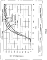
- Fig. 3 is a result measured under a condition with 50 ppm of the NH 3 gas, 10 L/min of the sample flow rate, 2 m of the sample piping length, a temperature of the piping at a room temperature (about 25°C).
- the response time is a period from T 10 (at a time when the measurement shows 10 % concentration) to T 90 (at a time when the measurement shows 90 % concentration).
- each of the response time is 1.1 second for the PTFE pipe, 1.8 second for the ordinal SUS pipe, 1.4 second for the mirror finished SUS pipe, 1.8 second for the surface treated SUS pipe. From these results, it becomes clear that the PTFE pipe is the most superior from a viewpoint of the response time.
- the negative pressure pump 24 that is connected to the measurement cell 21 keeps inside of the measurement cell 21 at the negative pressure and keeps a flow channel from a downstream side of the flow rate limit part 32 (concretely, the critical flow orifice CFO2) to the measurement cell 21 at the negative pressure from a starting time of the sampling to an ending time of the measurement
- the flow channel from the measurement cell 21 to the flow control limit part 32 of the heating pipe 4 becomes at the negative pressure that is generally the same pressure (for example, 25 kPa) as that of the measurement cell 21.
- the flow channel from the downstream side of the flow rate limit part 32 (concretely, the critical flow orifice CFO2) to the measurement cell 21 comprises a flow channel in the heating pipe 4, a flow channel in the introduction port 2P and a flow channel in an internal connecting pipe 25 connecting the introduction port 2P and the measurement cell 21.
- a zero gas pipe 6 to supply the measurement cell 21 with a zero gas in order to conduct zero point adjustment of the exhaust gas analyzer 100 (concretely, the light detecting part 23) and a span gas pipe 7 to supply the measurement cell 21 with a span gas in order to conduct span adjustment of the exhaust gas analyzer 100 (concretely, the light detecting part 23) are connected to the measurement cell 21.
- An open and close valve 61, 71 such as a solenoid valve to switch the gas supply is arranged for the zero gas pipe 6 and the span gas pipe 7 respectively.
- the zero gas pipe 6 and the span gas pipe 7 converges in the upstream side of the critical flow orifice (CFO) 8 as being the flow rate limit element, and the zero gas and the span gas are supplied to the measurement cell 21 through the critical flow orifice 8.
- the critical flow orifice 8 and the pipe near the critical flow orifice 8 are heated at, for example, 113 °C or 191 °C similar to the flow rate limit part 32 of the flow rate control unit 3.
- a buffer tank 26 is arranged between the negative pressure pump 24 and the measurement cell 21.
- the buffer tank 26 prevents fluctuation of the flow rate of the sample gas introduced into the measurement cell 21 due to pulsation of the negative pressure pump 24.
- a drain separator 27 and a drain pot 28 are connected in the downstream side of the negative pressure pump 24. The exhaust gas separated from the drain by the drain separator 27 is discharged outside from the drain separator 27. In addition, the drain separated from the exhaust gas by the drain separator 27 is housed in the drain pot 28 and then discharged.
- the flow rate limit part 32 of the flow rate control unit 3 is the critical flow orifice, and it is not possible to adjust the pressure of the sample gas introduced into the measurement cell 21 by the negative pressure pump 24 alone.
- a flow rate pressure adjust mechanism 5 to adjust the pressure of the sample gas introduced into the measurement cell 21 is arranged.
- the flow rate pressure adjust mechanism 5 is arranged on the connecting pipe between the negative pressure pump 24 and the measurement cell 21 and comprises a flow channel 51 to introduce a compensation gas such as atmospheric air, a filter 52 arranged on the flow channel 51 and a regulator 53 such as a pressure adjusting valve to adjust a flow rate of the compensation gas.
- the regulator 53 adjusts the pressure of the compensation gas so as to make inside of the measurement cell 21 at a constant pressure. Since a regulator is not arranged between the exhaust pipe and the measurement cell 21, there is in no danger of NH 3 adsorption by the regulator.
- the flow channel 51 is connected to the buffer tank 26.
- the flow rate limit part 32 is arranged in the upstream side end part of the heating pipe 4 arranged outside of the body 2 and inside of the measurement cell 21 and the flow channel from the downstream side of the flow rate limit part 32 to the measurement cell 21 are made at the negative pressure, it is possible to enlarge the area at the negative pressure of the flow channel connecting to the measurement cell 21 as much as possible, thereby enabling to reduce adsorption of the NH 3 component.
- the flow rate limit part 32 is arranged and the negative pressure is kept by the negative pressure pump 24 from the starting time of the sampling to the ending time of the measurement, it is possible to prevent the downstream side of the flow rate limit part 32 from being at a positive pressure due to a flowing pressure of the sample gas, thereby enabling to prevent attachment of the NH 3 component.
- the flow rate limit part 32 is arranged in the upstream side end part of the heating pipe 4, the negative pressurized sample gas is heated, thereby enabling further to prevent a dissolution loss of the NH 3 component associated with due condensation in the heating pipe 4.
- the absorption spectrum at an atmospheric pressure is monitored, it is known that the absorption peak is wide. Then, if inside of the measurement cell 21 is kept at the negative pressure, it is possible to obtain a sharper peak, thereby enabling to reduce an interference influence on the absorption peak of the NH 3 component.
- the present claimed invention is not limited to the above-mentioned embodiment.
- the flow rate limit part is arranged in the upstream side end part of the heating pipe 4 so as to maximize the negative pressurized flow rate volume, however, the flow rate limit part may be arranged on the heating pipe.
- a vacuum regulator such as a pressure adjust valve, a capillary, or a venturi may be used as the flow rate limit part.
- the NH 3 component is explained as the adsorptive gas, however, a gas component of high adsorption such as a hydrocarbon (HC) component may be analyzed.
- a gas component of high adsorption such as a hydrocarbon (HC) component
- hydrocarbon (HC) component represented aromatic hydrocarbon such toluene, alcohol such as methanol or ethanol, and high boiling point hydrocarbon (HC).
- high adsorptive gas component represented is a molecule having a polar character such as NO 2 , SO 2 , and H 2 O.
- the body 2 and the flow rate control unit 3 are separately arranged, however, they may be integrally formed.
Landscapes
- Physics & Mathematics (AREA)
- Spectroscopy & Molecular Physics (AREA)
- Health & Medical Sciences (AREA)
- Life Sciences & Earth Sciences (AREA)
- Chemical & Material Sciences (AREA)
- Analytical Chemistry (AREA)
- Biochemistry (AREA)
- General Health & Medical Sciences (AREA)
- General Physics & Mathematics (AREA)
- Immunology (AREA)
- Pathology (AREA)
- Investigating Or Analysing Materials By Optical Means (AREA)
- Sampling And Sample Adjustment (AREA)
Description
- This invention relates to a gas analyzer that measures a concentration of a component of a gas having the adsorption such as an ammonia (NH3) component or a hydrocarbon (HC) component contained in a sample gas such as an exhaust gas.
- Recently, due to growing interest in an environmental problem, it has been demanded further more reduction of an amount of NOx emission from an automobile. Then, various kinds of NOx after treatment devices such as a lean NOx trap catalyst for gasoline engine or a selective catalytic reduction (SCR) for diesel engine have been actively researched and developed. In order to evaluate NOx after treatment devices, a measurement of various nitrogen compounds such as NO, NO2, N2O, NH3 gets attention. Especially, for evaluation of the selective catalytic reduction (SCR), the measurement of NH3 becomes important to evaluate NH3 slip. In addition, since there is a regulation on NH3 in the EURO VI scheduled to be enforced in 2014 in EU, a measurement that can be conducted at a low concentration of NH3 with high response speed is required.
- As shown in the
patent document 1, a conventional gas analyzer used for measuring a concentration of NH3 introduces an exhaust gas emitted from an exhaust pipe of an automobile into a measurement cell by means of a sampling pipe and measures the concentration of NH3 by the use of a light absorbance of NH3. - However, with the gas analyzer of this sampling method, there is a problem that NH3 contained in the exhaust gas is highly adherent and attaches to an inner wall of the sampling pipe or an inner wall of a flow rate control device arranged on a pipe. As a result, there is a problem that it is difficult to measure the concentration of NH3 with high accuracy. Especially, the concentration of the NH3 contained in the exhaust gas is low so that it takes time to introduce the exhaust gas into the measurement cell due to the inner wall of the pipe. As a result of this, the response speed is lowered so that there is a problem that it is difficult to conduct the measurement at a high speed.
- In addition, with the gas analyzer of this sampling method, a suction pump is arranged between the sampling pipe and the measurement cell to sample the exhaust gas and to introduce the sampled sample gas into the measurement cell.
- However, in case that the exhaust gas is sampled by the use of the suction pump, a pressure of inside of the sampling pipe fluctuates between a negative pressure and a positive pressure by the pressure of the exhaust gas emitted from the exhaust pipe (a tail pipe). In case that the pressure becomes at the positive pressure, NH3 easily attaches to the inner wall of the sampling pipe. In addition, the measurement of the concentration conducted in the measurement cell is a Fourier transform infrared spectroscopy (FTIR) or a Non-dispersive infrared analyzing method (NDIR). In order to conduct the measurement, it is required that the pressure in the measurement cell is made generally the same as the atmospheric pressure. With this arrangement, there is a problem that NH3 attaches to inside of the measurement cell. Furthermore, with this arrangement, since the exhaust gas introduced into the measurement cell passes a pump, there is also a problem that NH3 attaches to the pump. Further technological background can be found in
US 2006/044562 A1 ,JP 9061361 A US 2008/092648 A1 - Patent document 1: Japan patent laid-open number
2001-159587 - In order to solve all of the problems the present claimed invention focuses attention on that there is no need of measuring the sample gas in the measurement cell at generally the same pressure as the atmospheric pressure if the gas component is analyzed by the absorptiometry by the use of the laser light and a main object of this invention is to make it possible to measure the concentration of the adsorptive gas component having a polar characteristic such as NH3 component or HC component with high accuracy even though the concentration is low and to improve the response speed of the concentration measurement
- More specifically, the adsorptive gas analyzer in accordance with this invention is to measure a concentration of an adsorptive component having a polar character contained in a sample gas, and is characterized by comprising a body that has a measurement cell to measure the sample gas and an introduction port to introduce the sample gas into the measurement cell, a laser light irradiation part that irradiates the laser light on the measurement cell, a heating pipe that is connected to the introduction port and that applies heat to the sample gas introduced into the introduction port, a flow rate limit part that makes the sample gas at a negative pressure and that introduces the negative-pressurized heated sample gas into the body, and a negative pressure pump that is connected to the measurement cell, that keeps inside of the measurement cell at the negative pressure from a starting time of a sampling to an ending time of the measurement and that keeps a flow channel from a downstream side of the flow rate limit part to the measurement cell at the negative pressure from the starting time of the sampling to the ending time of the measurement
- In accordance with this arrangement, since the heating pipe and the flow rate limit part are arranged outside of the body and inside of the measurement cell and the flow channel from the downstream side of the flow rate limit part to the measurement cell are made at the negative pressure by means of the negative pressure pump, it is possible to enlarge the area at the negative pressure in the flow channel connected to the measurement cell, thereby enabling to reduce adsorption of the adsorptive gas component having the polar character such as NH3 or HC. In addition, since the flow rate limit part is arranged and the negative pressure is kept by the negative pressure pump from the starting time of the sampling to the ending time of the measurement, it is possible to prevent the downstream side of the flow rate limit part from being at a positive pressure due to a flowing pressure of the sample gas, thereby enabling to prevent attachment of the adsorptive gas component. With this arrangement, it is possible to measure the concentration of the adsorptive gas having a polar character such as the NH3 component or the HC component with high accuracy even though its concentration is low, and furthermore it is possible to improve the response speed of measuring the concentration. In addition, since the negative pressurized sample gas is heated by the heating pipe, it is possible to prevent a dissolution loss of the adsorptive gas component associated with the due condensation in the pipe, thereby enabling to further improve the measurement accuracy and the response speed. Furthermore, if the absorption spectrum at an atmospheric pressure is monitored, it is known that the absorption peak is wide. Then if inside of the measurement cell is kept at the negative pressure, it is possible to obtain a sharper peak, thereby enabling to reduce an interference influence on the absorption peak by the adsorptive gas component
- If the inside of the measurement cell and the flow channel of the heating pipe from the downstream side of the flow rate limit part to the measurement cell is kept at the negative pressure, it is possible to reduce the adsorption amount of the adsorptive gas component attaching to the inner wall. However, with this arrangement, the amount of the sample gas introduced into the measurement cell is also decreased. As a result, there is a problem that the obtained detected signal is decreased so that the detecting sensitivity is deteriorated. In order to solve this problem, it is preferable that the measurement cell is of a multiple reflection type. With this arrangement, it is possible to lengthen the optical length in the measurement cell so that the detected signal is increased, thereby enabling to improve the detecting sensitivity. Especially, it is effective for measuring the concentration of the gas of low concentration such as NH3 contained in the sample gas. Since this invention irradiates the laser light, it is possible to elongate the optical length effectively if the cell of the multiple reflection type is used.
- In accordance with this invention having the above-mentioned arrangement, it is possible to measure a concentration of an adsorptive gas component having a polar character such as NH3 even though the concentration is low, and to improve a response speed of the measurement of the concentration.
-
-
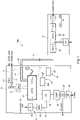
Fig. 1 is a configuration diagram schematically showing an exhaust gas analyzer in accordance with this embodiment. -
Fig. 2 is a view showing a pressure fluctuation of an absorption spectrum of a sample gas having the adsorption. -
Fig. 3 is an experiment result showing a response time in case of using various kinds of heating pipes. - One embodiment of an
exhaust gas analyzer 100 in accordance with this invention will be explained with reference to drawings. - The
exhaust gas analyzer 100 in accordance with this embodiment is connected to, for example, an exhaust pipe (a tail pipe) of an automobile, and measures a concentration of NO, NO2, N2O and NH3 contained in an exhaust gas as being a sample gas emitted from the exhaust pipe by the use of an absorptiometry. - Concretely, the
exhaust gas analyzer 100 comprises, as shown inFig. 1 , abody 2 to measure the sample gas, a flowrate control unit 3 that is arranged separately from thebody 2 and that is mounted on the exhaust pipe of the automobile, and aheating pipe 4 that is connected to thebody 2 and the flowrate control unit 3 and that introduces the exhaust gas introduced from the flowrate control unit 3 into thebody 2. Thebody 2 and the flowrate control unit 3 are arranged at a different position respectively, and connected by only theheating pipe 4 without any additional casing that houses both thebody 2 and the flowrate control unit 3. - The
body 2 comprises ameasurement cell 21 of a multiple reflection type that measures the sample gas, a laserlight irradiation part 22 that irradiates the laser light L1 having high linearity on the sample gas in themeasurement cell 21 by introducing the laser light L1 from a light introducing window of themeasurement cell 21, alight detecting part 23 that detects the transmitted laser light L2 coming from themeasurement cell 21, and anegative pressure pump 24 that is connected to themeasurement cell 21 and that makes inside of themeasurement cell 21 at a negative pressure. Since themeasurement cell 21 is of the multiple reflection type, it is possible to heighten the detection sensitivity even though the concentration of the measurement component is low. In addition, thenegative pressure pump 24 keeps the inside of themeasurement cell 21 at the negative pressure within a range, for example, between 1 kPa (at this pressure it becomes difficult to conduct the measurement because the gas concentration is too small) and 80 kPa (at this pressure interference with other gas component occurs easily because the peak is broad), and preferably keeps the inside of themeasurement cell 21 at the negative pressure within a range between 20 kPa and 50 kPa that is a pressure range at which adsorption of NH3 is difficult to occur, and the interference with other gas component does not occur with realizing a gas concentration that can be measured. As mentioned, if the negative pressure falls within 20 kPa through 50 kPa, it is possible to make both a pressure in themeasurement cell 21 and a pressure in theheating pipe 4 equal by means of the singlenegative pressure pump 24. As shown inFig. 2 , for the absorption spectrum of the sample gas having the adsorptive gas component, a peak begins to form at less than or equal to 80 kPa and its peak is clearly expressed at less than or equal to 50 kPa. - Furthermore, the
body 2 has anintroduction port 2P to which theheating pipe 4, to be described later, is connected and that is to introduce the exhaust gas flowing in theheating pipe 4 into themeasurement cell 21. In order to prevent dew condensation of moisture in the exhaust gas, theintroduction port 2P, the internal connectingpipe 25 and themeasurement cell 21 are heated at, for example, 113 °C or 191 °C. - The laser
light irradiation part 22 comprises alaser light source 221 to irradiate the laser light L1, and a guide mechanism 222 comprising a reflection mirror to guide the light from thelaser light source 221 to themeasurement cell 21. In this embodiment, an object as the adsorptive gas component is NH3, and it can be conceived that thelaser light source 221 uses a tunable laser that irradiates the laser light having an infrared region wavelength such as a mid-infrared region or a near-infrared region where NH3 has an absorption property or the laser light having an oscillation wavelength in an ultraviolet region, and uses, for example, a quantum cascade laser (QCL), a semiconductor laser such as a tunable semiconductor laser, a solid laser or a liquid laser. - It is especially preferable to use the quantum cascade laser (QCL) as the
laser light source 221. A quantum cascade laser element oscillates the laser light by means of an electric current pulse having a certain interval. Since an oscillation frequency from the laser element depends on the temperature, the oscillation frequency repeats a scan in a narrow frequency range in terms of result The absorptionmetric method using the QCL (QCL-IR method) uses an element whose oscillation central frequency is adjusted so as to fall the absorption peak position of a component as a target within this frequency range. As will be described later, since a density of the adsorptive gas component such as NH3 in the sample gas is small and its absorption peak becomes small in the negative-pressurizedmeasurement cell 21, the sensitivity drops. However, if the QCL having an oscillation wavelength (a pulse width is 500 nsec) in the near-infrared region is used, it is possible to make the absorption peak big. As a result, it is possible to measure the concentration of the adsorptive gas component without deteriorating the sensitivity under the negative pressure and to obtain a high speed response. - The
light detecting part 23 detects the transmitted laser light L2 from themeasurement cell 21 after multiple reflection in themeasurement cell 21, and it can be conceived to use, for example, an MCT (HgCdTe)detector 23 of a normal temperature operation type. A guide mechanism 232 comprising a reflection mirror to guide the transmitted laser light L2 to thelight detector 231 is arranged between theMCT detector 231 and themeasurement cell 21. The light intensity signal obtained by thelight detector 231 is output to a calculation device, not shown in drawings. The light absorption of each component is calculated and then the concentration of each component is calculated by the calculation device. - The flow
rate control unit 3 is connected to the exhaust pipe of the automobile, and comprises afilter 31 to remove a dust in the exhaust gas emitted from the exhaust pipe and a flowrate limit part 32 to limit a flow rate of the exhaust gas passing thefilter 31. In addition, it is preferable that the flowrate control unit 3 is mounted directly on an exhaust opening or on a position within 2 m from the exhaust opening through a piping. It is especially preferable that the flowrate control unit 3 is mounted on a position within 50 cm from the exhaust opening. With this arrangement, it is possible to make the exhaust gas from the exhaust pipe at the negative pressure in the upstream side at an early stage. - The
filter 31 comprises, for example, acylindrical filter 31a that is arranged in the upstream side and that can be exchanged by a user, and, for example, a disk-shapedfilter 31b that is arranged inside of the flowrate control unit 3 and in the downstream side and that can not be exchanged by a user. In addition, a critical flow orifice (CFO) is used as the flowrate limit part 32 to shorten a response time by lessening an area to contact the gas. Since the flowrate control unit 3 is a unit having thefilter 31 and the critical flow orifice (CFO), it can be downsized. - Concretely, the flow
rate limit part 32 comprises two critical flow orifices CFO1 and CFO2 arranged in serial. In addition, a bifurcated flow channel 33 having a check valve CV is arranged between two critical flow orifices CFO1 and CFO2. With this arrangement, in case that the exhaust gas flowing in the flowrate control unit 3 is at a high pressure, a part of the sample gas is discharged outside from the bifurcated flow channel 33. In addition, theheating pipe 4, to be described later, is connected to the critical flow orifice CFO2 in the downstream side. In order to prevent dew condensation of moisture in the exhaust gas, thefilter 31 and the flowrate limit part 32 are heated at, for example, 113 °C or 191 °C. - The
heating pipe 4 connects thebody 2 and the flowrate control unit 3, each of which is separately arranged, and comprises a pipe surrounded by a heater. Concretely, a downstream side of theheating pipe 4 is connected to theintroduction port 2P of thebody 2 and an upstream side of theheating pipe 4 is connected to the flow rate limit part 32 (concretely, the critical flow orifice CFO2) of the flowrate control unit 3. - The
heating pipe 4 applies heat to the exhaust gas passing the flowrate control unit 3 at 100 °C through 200 °C and introduces the heated exhaust gas into theintroduction port 2P of thebody 2. If a temperature of the exhaust gas is lower than 100 °C, the adsorptive gas component such as NH3 gas is easily adsorbed or condensed in theheating pipe 4. Meanwhile, if the temperature of the exhaust gas is higher than 200 °C, in case that theheating pipe 4 is made of, for example, a fluorocarbon resin (PTFE), the PTFE might melt In this embodiment, the exhaust gas is heated at 113 °C that is the same temperature as the heated temperature of themeasurement cell 21 and introduced into theintroduction port 2P of thebody 2. With this arrangement, the flowrate limit part 32 is arranged in the upstream side end part of theheating pipe 4. - As a material of a pipe of the
heating pipe 4 conceived is a stainless steel (SUS) or a fluorocarbon resin (PTEE), however, it is preferable to use the fluorocarbon resin (PTEE) in order to reduce adsorption of NH3 and to shorten a response time. In case that the stainless steel (SUS) is used, it can be conceived that an inner surface of theheating pipe 4 is coated with a porous material such as porous silicon so as not to adsorb the NH3 gas as being a polar molecule. In addition, it is possible to further decrease adsorption of NH3 by providing a surface treatment or a mirror finishing on an inner wall surface of theheating pipe 4. - In case of using (1) the fluorocarbon resin (PTEE), (2) the ordinal stainless steel (SUS), (3) the mirror finished stainless steel (SUS), (4) the surface treated stainless steel (SUS) as the material of the pipe of the
heating pipe 4, experiment results of the response time are shown inFig. 3. Fig. 3 is a result measured under a condition with 50 ppm of the NH3 gas, 10 L/min of the sample flow rate, 2 m of the sample piping length, a temperature of the piping at a room temperature (about 25°C). The response time is a period from T10 (at a time when the measurement shows 10 % concentration) to T90 (at a time when the measurement shows 90 % concentration). As is clear fromFig. 3 , each of the response time is 1.1 second for the PTFE pipe, 1.8 second for the ordinal SUS pipe, 1.4 second for the mirror finished SUS pipe, 1.8 second for the surface treated SUS pipe. From these results, it becomes clear that the PTFE pipe is the most superior from a viewpoint of the response time. - In the
exhaust gas analyzer 100 of this embodiment, thenegative pressure pump 24 that is connected to themeasurement cell 21 keeps inside of themeasurement cell 21 at the negative pressure and keeps a flow channel from a downstream side of the flow rate limit part 32 (concretely, the critical flow orifice CFO2) to themeasurement cell 21 at the negative pressure from a starting time of the sampling to an ending time of the measurement Namely, the flow channel from themeasurement cell 21 to the flowcontrol limit part 32 of theheating pipe 4 becomes at the negative pressure that is generally the same pressure (for example, 25 kPa) as that of themeasurement cell 21. In this embodiment, the flow channel from the downstream side of the flow rate limit part 32 (concretely, the critical flow orifice CFO2) to themeasurement cell 21 comprises a flow channel in theheating pipe 4, a flow channel in theintroduction port 2P and a flow channel in an internal connectingpipe 25 connecting theintroduction port 2P and themeasurement cell 21. - A zero
gas pipe 6 to supply themeasurement cell 21 with a zero gas in order to conduct zero point adjustment of the exhaust gas analyzer 100 (concretely, the light detecting part 23) and aspan gas pipe 7 to supply themeasurement cell 21 with a span gas in order to conduct span adjustment of the exhaust gas analyzer 100 (concretely, the light detecting part 23) are connected to themeasurement cell 21. An open andclose valve gas pipe 6 and thespan gas pipe 7 respectively. In addition, the zerogas pipe 6 and thespan gas pipe 7 converges in the upstream side of the critical flow orifice (CFO) 8 as being the flow rate limit element, and the zero gas and the span gas are supplied to themeasurement cell 21 through thecritical flow orifice 8. Thecritical flow orifice 8 and the pipe near thecritical flow orifice 8 are heated at, for example, 113 °C or 191 °C similar to the flowrate limit part 32 of the flowrate control unit 3. With this arrangement, it becomes possible to conduct the zero adjustment and the span adjustment under the same condition as that of the measurement - In addition, a
buffer tank 26 is arranged between thenegative pressure pump 24 and themeasurement cell 21. Thebuffer tank 26 prevents fluctuation of the flow rate of the sample gas introduced into themeasurement cell 21 due to pulsation of thenegative pressure pump 24. Adrain separator 27 and adrain pot 28 are connected in the downstream side of thenegative pressure pump 24. The exhaust gas separated from the drain by thedrain separator 27 is discharged outside from thedrain separator 27. In addition, the drain separated from the exhaust gas by thedrain separator 27 is housed in thedrain pot 28 and then discharged. - Furthermore, the flow
rate limit part 32 of the flowrate control unit 3 is the critical flow orifice, and it is not possible to adjust the pressure of the sample gas introduced into themeasurement cell 21 by thenegative pressure pump 24 alone. Then, in this embodiment, a flow rate pressure adjustmechanism 5 to adjust the pressure of the sample gas introduced into themeasurement cell 21 is arranged. The flow rate pressure adjustmechanism 5 is arranged on the connecting pipe between thenegative pressure pump 24 and themeasurement cell 21 and comprises aflow channel 51 to introduce a compensation gas such as atmospheric air, afilter 52 arranged on theflow channel 51 and aregulator 53 such as a pressure adjusting valve to adjust a flow rate of the compensation gas. Theregulator 53 adjusts the pressure of the compensation gas so as to make inside of themeasurement cell 21 at a constant pressure. Since a regulator is not arranged between the exhaust pipe and themeasurement cell 21, there is in no danger of NH3 adsorption by the regulator. In this embodiment, theflow channel 51 is connected to thebuffer tank 26. - In accordance with the
exhaust gas analyzer 100 of this embodiment having the above-mentioned arrangement, since the flowrate limit part 32 is arranged in the upstream side end part of theheating pipe 4 arranged outside of thebody 2 and inside of themeasurement cell 21 and the flow channel from the downstream side of the flowrate limit part 32 to themeasurement cell 21 are made at the negative pressure, it is possible to enlarge the area at the negative pressure of the flow channel connecting to themeasurement cell 21 as much as possible, thereby enabling to reduce adsorption of the NH3 component In addition, since the flowrate limit part 32 is arranged and the negative pressure is kept by thenegative pressure pump 24 from the starting time of the sampling to the ending time of the measurement, it is possible to prevent the downstream side of the flowrate limit part 32 from being at a positive pressure due to a flowing pressure of the sample gas, thereby enabling to prevent attachment of the NH3 component. With this arrangement, it is possible to conduct the measurement with high accuracy even though the concentration of the NH3 component is low, and furthermore it is possible to improve the response speed of measuring the concentration. Since the NH3 component is difficult to be detached if once adsorbed, it is required to keep the negative pressure on a constant basis from the starting time of the sampling to the ending time of the measurement - In addition, since the flow
rate limit part 32 is arranged in the upstream side end part of theheating pipe 4, the negative pressurized sample gas is heated, thereby enabling further to prevent a dissolution loss of the NH3 component associated with due condensation in theheating pipe 4. - Furthermore, if the absorption spectrum at an atmospheric pressure is monitored, it is known that the absorption peak is wide. Then, if inside of the
measurement cell 21 is kept at the negative pressure, it is possible to obtain a sharper peak, thereby enabling to reduce an interference influence on the absorption peak of the NH3 component. - The present claimed invention is not limited to the above-mentioned embodiment.
- For example, in the above-mentioned embodiment, the flow rate limit part is arranged in the upstream side end part of the
heating pipe 4 so as to maximize the negative pressurized flow rate volume, however, the flow rate limit part may be arranged on the heating pipe. - In addition, in addition to the critical flow orifice, a vacuum regulator such as a pressure adjust valve, a capillary, or a venturi may be used as the flow rate limit part.
- Furthermore, in the above-mentioned embodiment, the NH3 component is explained as the adsorptive gas, however, a gas component of high adsorption such as a hydrocarbon (HC) component may be analyzed. As an example of the hydrocarbon (HC) component represented are aromatic hydrocarbon such toluene, alcohol such as methanol or ethanol, and high boiling point hydrocarbon (HC). In addition, as the high adsorptive gas component represented is a molecule having a polar character such as NO2, SO2, and H2O.
- In the above-mentioned embodiment, the
body 2 and the flowrate control unit 3 are separately arranged, however, they may be integrally formed. -
- 100 exhaust gas analyzer (adsorptive gas analyzer)
- 2 body
- 21 measurement cell
- 2P introduction port
- 22 laser light irradiation part
- 24 negative pressure pump
- 32 flow rate limit part
- 4 heating pipe
Claims (3)
- An adsorptive gas analyzer (100) to measure a concentration of an adsorptive component having a polar character contained in a sample gas,
comprising:a body (2) that has a measurement cell (21) to measure the sample gas and an introduction port (2P) to introduce the sample gas into the measurement cell (21),a laser light irradiation part (22) that irradiates laser light on the measurement cell (21),a heating pipe (4) that is connected to the introduction port (2P) and that applies heat to the sample gas introduced into the introduction port (2P),a flow rate limit part (32) that is arranged upstream of the heating pipe (4) and that makes the sample gas at a negative pressure and that introduces the heated negative-pressurized sample gas into the body (2), anda negative pressure pump (24) that is arranged downstream of the measurement cell (21) and that is connected to the measurement cell (21), that is adapted to keep the inside of the measurement cell (21) at the negative pressure from a starting time of a sampling to an ending time of the measurement and that is adapted to keep a flow channel from a downstream side of the flow rate limit part (32) to the measurement cell (21) at the negative pressure from the starting time of the sampling to the ending time of the measurement; whereinthe adsorptive component is NH3, HC, NO2, SO2 or H2O. - The adsorptive gas analyzer (100) described in claim 1,
wherein the measurement cell (21) is of a multiple reflection type. - A method of measuring a concentration of an adsorptive component having a polar character contained in a sample gas using an adsorptive gas analyzer (100) comprising a body (2) that has a measurement cell (21) to measure the sample gas and an introduction port (2P) to introduce the sample gas into the measurement cell (21); a laser light irradiation part (22) that irradiates laser light on the measurement cell (21); a heating pipe (4) that is connected to the introduction port (2P) and that applies heat to the sample gas introduced into the introduction port (2P); a flow rate limit part (32) that is arranged upstream of the heating pipe (4) and that makes the sample gas at a negative pressure and that introduces the heated negative-pressurized sample gas into the body (2); and a negative pressure pump (24) that is arranged downstream of the measurement cell (21) and that is connected to the measurement cell (21), the method comprising a step of keeping the inside of the measurement cell (21) at the negative pressure from a starting time of a sampling to an ending time of the measurement and keeping a flow channel from a downstream side of the flow rate limit part (32) to the measurement cell (21) at the negative pressure from the starting time of the sampling to the ending time of the measurement; wherein
the adsorptive component is NH3, HC, NO2, SO2 or H2O.
Applications Claiming Priority (2)
| Application Number | Priority Date | Filing Date | Title |
|---|---|---|---|
| JP2010114813 | 2010-05-18 | ||
| JP2011052090A JP5667912B2 (en) | 2010-05-18 | 2011-03-09 | Adsorbable gas analyzer |
Publications (3)
| Publication Number | Publication Date |
|---|---|
| EP2388570A1 EP2388570A1 (en) | 2011-11-23 |
| EP2388570B1 EP2388570B1 (en) | 2019-07-03 |
| EP2388570B2 true EP2388570B2 (en) | 2022-10-12 |
Family
ID=44483738
Family Applications (1)
| Application Number | Title | Priority Date | Filing Date |
|---|---|---|---|
| EP11004047.4A Active EP2388570B2 (en) | 2010-05-18 | 2011-05-16 | Adsorptive gas analyzer |
Country Status (4)
| Country | Link |
|---|---|
| US (1) | US8564779B2 (en) |
| EP (1) | EP2388570B2 (en) |
| JP (1) | JP5667912B2 (en) |
| CN (1) | CN102338740B (en) |
Families Citing this family (34)
| Publication number | Priority date | Publication date | Assignee | Title |
|---|---|---|---|---|
| CN103217319B (en) * | 2012-01-19 | 2017-05-17 | 深圳迈瑞生物医疗电子股份有限公司 | Sampling pump and gas analyzer |
| JP5752067B2 (en) * | 2012-02-14 | 2015-07-22 | 株式会社堀場製作所 | Exhaust gas sampling device |
| CN103424261B (en) | 2012-05-23 | 2017-05-24 | 株式会社堀场制作所 | Exhaust gas analyzing apparatus, exhaust gas analyzing system and method of operating the same |
| JP5732432B2 (en) * | 2012-05-23 | 2015-06-10 | 株式会社堀場製作所 | Exhaust gas analyzer |
| DK2948761T3 (en) * | 2013-01-23 | 2023-09-04 | California Inst Of Techn | Tunable miniature laser spectrometer for detecting a trace gas |
| MY170542A (en) * | 2013-02-01 | 2019-08-16 | Serge V Monros | Hydrogen on-demand fuel system for internal combustion engines |
| CN103234908B (en) * | 2013-04-26 | 2015-01-07 | 青岛科技大学 | General-purpose connecting device for temperature control gas infrared analysis |
| DE102014100691B3 (en) | 2014-01-22 | 2015-01-08 | Avl Emission Test Systems Gmbh | Device for determining the concentration of at least one gas in a sample gas stream by means of infrared absorption spectroscopy |
| DE102014101915B4 (en) * | 2014-02-14 | 2024-08-01 | Avl Analytical Technologies Gmbh | Device and method for determining the concentration of at least one gas in a sample gas stream by means of infrared absorption spectroscopy |
| JP6472706B2 (en) * | 2014-05-15 | 2019-02-20 | 株式会社堀場製作所 | Exhaust gas analyzer |
| KR102371413B1 (en) * | 2014-06-19 | 2022-03-04 | 단포스 아이엑스에이 에이/에스 | Probe for gas sensor having purge gas protection |
| US9501827B2 (en) | 2014-06-23 | 2016-11-22 | Exxonmobil Upstream Research Company | Methods and systems for detecting a chemical species |
| JP6300753B2 (en) * | 2015-03-31 | 2018-03-28 | 日本電信電話株式会社 | N2O analyzer and analysis method |
| US9500580B1 (en) | 2015-06-04 | 2016-11-22 | General Electric Company | Gas detector and method of detection |
| JP6618447B2 (en) * | 2015-12-10 | 2019-12-11 | 株式会社堀場製作所 | Vehicle speed pattern display device, program used in this device, running test method, and automatic driving device |
| CN107024442A (en) * | 2015-12-15 | 2017-08-08 | 株式会社堀场制作所 | Multipath reflection type unit, analytical equipment, the injection method of exhaust gas analyzer and light |
| WO2017139719A1 (en) * | 2016-02-12 | 2017-08-17 | Leo Breton | Real time fluid species mass flow meter |
| JP6796016B2 (en) * | 2016-04-18 | 2020-12-02 | 株式会社堀場製作所 | Spectral analyzer and spectroscopic analysis method |
| CN106370622A (en) * | 2016-09-06 | 2017-02-01 | 武汉市农业科学技术研究院农业机械化科学研究所 | Pumping type laser ammonia gas online monitoring device suitable for agricultural breeding environment |
| US10712242B2 (en) * | 2017-02-28 | 2020-07-14 | Process Hg Group Holdings, Llc | Mercury-in-gas sampling system |
| CN109253982A (en) * | 2017-07-12 | 2019-01-22 | 上海通用检测技术研究所 | infrared leak detector |
| JP6967387B2 (en) | 2017-07-14 | 2021-11-17 | 株式会社堀場製作所 | Gas analyzers, programs for gas analyzers, and gas analysis methods |
| CN109596538B (en) * | 2017-10-03 | 2023-08-25 | 株式会社堀场制作所 | Analysis device and analysis method |
| JP7121536B2 (en) * | 2018-05-18 | 2022-08-18 | 株式会社堀場製作所 | Semiconductor laser device manufacturing method, semiconductor laser device therefor, and gas analysis device |
| CN108535135B (en) * | 2018-05-24 | 2023-08-15 | 中国地质大学(北京) | Experimental system and method for measuring gas adsorption-diffusion-displacement |
| WO2020150112A1 (en) * | 2019-01-16 | 2020-07-23 | Indrio Technologies, Inc | Laser-based in-situ exhaust gas sensor |
| FI128319B (en) * | 2019-02-12 | 2020-03-13 | Teknologian Tutkimuskeskus Vtt Oy | Method for detecting carbon dioxide in a gaseous sample, equipment and use of an anion exchange resin |
| JP7168767B2 (en) * | 2019-04-08 | 2022-11-09 | 株式会社日立ハイテク | automatic analyzer |
| CN110927330B (en) * | 2019-05-05 | 2022-03-25 | 唐山师范学院 | Diesel truck exhaust emission analysis device based on OBD data acquisition |
| EP3957979B1 (en) * | 2019-05-15 | 2025-04-16 | HORIBA, Ltd. | Sample analyzing apparatus |
| JPWO2023063136A1 (en) | 2021-10-12 | 2023-04-20 | ||
| DE112022006134T5 (en) * | 2021-12-23 | 2024-10-02 | Horiba, Ltd. | EXHAUST GAS ANALYSIS DEVICE, EXHAUST GAS ANALYSIS METHOD AND PROGRAM FOR AN EXHAUST GAS ANALYSIS DEVICE |
| CN116223445A (en) * | 2023-05-05 | 2023-06-06 | 安徽中科智泰光电测控科技有限公司 | Underground multi-gas detector and detection system for mine |
| CN117092294B (en) * | 2023-08-24 | 2024-01-16 | 中国环境监测总站 | Exhaust gas concentration detection device and method |
Citations (4)
| Publication number | Priority date | Publication date | Assignee | Title |
|---|---|---|---|---|
| US4990780A (en) † | 1989-06-19 | 1991-02-05 | General Motors Corporation | Method for determining fuel and engine oil comsumption using tunable diode laser spectroscopy |
| US5445964A (en) † | 1994-05-11 | 1995-08-29 | Lee; Peter S. | Dynamic engine oil and fuel consumption measurements using tunable diode laser spectroscopy |
| EP0706042A1 (en) † | 1994-03-25 | 1996-04-10 | Nippon Sanso Corporation | Infrared spectrochemical gas analysis and apparatus used for the same |
| JP2000002656A (en) † | 1998-06-12 | 2000-01-07 | Horiba Ltd | Gas analyzer |
Family Cites Families (13)
| Publication number | Priority date | Publication date | Assignee | Title |
|---|---|---|---|---|
| CN2128385Y (en) * | 1992-07-03 | 1993-03-17 | 中国科学院大连化学物理研究所 | Negative pressure thermal conduction tester for capillary gas chromatography |
| JPH07270316A (en) * | 1994-03-31 | 1995-10-20 | Shimadzu Corp | Infrared gas analyzer |
| JP3924013B2 (en) * | 1995-08-28 | 2007-06-06 | 三菱重工業株式会社 | Ammonia concentration continuous measurement device |
| JP3495965B2 (en) * | 2000-02-28 | 2004-02-09 | 三菱住友シリコン株式会社 | Moisture monitoring device and semiconductor manufacturing device having the same |
| JP3281876B2 (en) * | 1999-10-26 | 2002-05-13 | 三菱重工業株式会社 | Dioxin analyzer and combustion control system |
| JP2001159587A (en) | 1999-12-01 | 2001-06-12 | Horiba Ltd | Gas analyzer |
| CN1310022C (en) * | 2001-10-26 | 2007-04-11 | 北京航天益来电子科技有限公司 | Gaseous pollutant micro-quantity extraction field analysis method and equipment |
| JP2003222591A (en) * | 2002-01-30 | 2003-08-08 | Yokogawa Electric Corp | Gas measurement device |
| US20060044562A1 (en) * | 2004-08-25 | 2006-03-02 | Norsk Elektro Optikk As | Gas monitor |
| US7354553B2 (en) * | 2005-05-02 | 2008-04-08 | Dirk Appel | Method and apparatus for detecting the presence of elemental mercury in a gas sample |
| US7511802B2 (en) * | 2006-05-26 | 2009-03-31 | Spectrasensors, Inc. | Measuring trace components of complex gases using gas chromatography/absorption spectrometry |
| US7728978B2 (en) * | 2006-10-18 | 2010-06-01 | Spectrasensors, Inc. | Detection of moisture in refrigerants |
| GR1006900B (en) * | 2007-02-14 | 2010-07-21 | Ζησης Σαμαρας | Diluter for exhaust gas sampling and method therefor. |
-
2011
- 2011-03-09 JP JP2011052090A patent/JP5667912B2/en active Active
- 2011-05-16 EP EP11004047.4A patent/EP2388570B2/en active Active
- 2011-05-17 US US13/109,876 patent/US8564779B2/en active Active
- 2011-05-18 CN CN201110141459.XA patent/CN102338740B/en active Active
Patent Citations (4)
| Publication number | Priority date | Publication date | Assignee | Title |
|---|---|---|---|---|
| US4990780A (en) † | 1989-06-19 | 1991-02-05 | General Motors Corporation | Method for determining fuel and engine oil comsumption using tunable diode laser spectroscopy |
| EP0706042A1 (en) † | 1994-03-25 | 1996-04-10 | Nippon Sanso Corporation | Infrared spectrochemical gas analysis and apparatus used for the same |
| US5445964A (en) † | 1994-05-11 | 1995-08-29 | Lee; Peter S. | Dynamic engine oil and fuel consumption measurements using tunable diode laser spectroscopy |
| JP2000002656A (en) † | 1998-06-12 | 2000-01-07 | Horiba Ltd | Gas analyzer |
Also Published As
| Publication number | Publication date |
|---|---|
| US8564779B2 (en) | 2013-10-22 |
| JP2012002799A (en) | 2012-01-05 |
| CN102338740B (en) | 2015-04-08 |
| CN102338740A (en) | 2012-02-01 |
| EP2388570B1 (en) | 2019-07-03 |
| EP2388570A1 (en) | 2011-11-23 |
| JP5667912B2 (en) | 2015-02-12 |
| US20110285998A1 (en) | 2011-11-24 |
Similar Documents
| Publication | Publication Date | Title |
|---|---|---|
| EP2388570B1 (en) | Adsorptive gas analyzer | |
| Yin et al. | Sub-ppb nitrogen dioxide detection with a large linear dynamic range by use of a differential photoacoustic cell and a 3.5 W blue multimode diode laser | |
| JP5985465B2 (en) | Gas analyzer | |
| KR102455470B1 (en) | Hydrogen gas sensor and method for measurement of hydrogen under atmospheric and elevated pressure | |
| US7499169B2 (en) | Fuel cell and product of combustion humidity sensor | |
| US9335235B2 (en) | Exhaust gas sampling device | |
| US10739255B1 (en) | Trace moisture analyzer instrument, gas sampling and analyzing system, and method of detecting trace moisture levels in a gas | |
| KR101460874B1 (en) | Ammonia compound concentration measuring device and ammonia compound concentration measuring method | |
| Sumizawa et al. | Real-time monitoring of nitric oxide in diesel exhaust gas by mid-infrared cavity ring-down spectroscopy | |
| US20190212260A1 (en) | Method and device for monitoring the quality of gaseous media | |
| JP6134483B2 (en) | Gas analyzer | |
| US10094771B2 (en) | Device and method for determining the concentration of at least one gas in a sample gas stream by means of infrared absorption spectroscopy | |
| KR20250023979A (en) | Gas continuous analysis system and gas continuous analysis method | |
| Degner et al. | High resolution led-spectroscopy for sensor application in harsh environment | |
| Thompson et al. | Characterization of a mid-infrared hollow waveguide gas cell for the analysis of carbon monoxide and nitric oxide | |
| JP4677462B2 (en) | Gas analyzer and gas cell pressure or flow rate control method using the gas analyzer | |
| WO2008011140A2 (en) | Humidity sensor for fuel cells and combustion exhaust streams | |
| Jeffers et al. | Real-time diode laser measurements of vapor-phase benzene | |
| Kondo et al. | Development Of On-board Multi-component Gas Analyzer Toward Euro 7 | |
| Tittel et al. | Sensitive detection of nitric oxide using a 5.26 μm external cavity quantum cascade laser based QEPAS sensor | |
| JP2011007534A (en) | Gas analyzing device, and method for controlling pressure or flow rate of gas cell using the same | |
| KR101784605B1 (en) | FTIR measurement system incorporating stabilization system and moisture removal of sample gas | |
| Rahman et al. | Development of a Fast Response Nitrogen Compounds Analyzer Using Quantum Cascade Laser for Wide-Range Measurement | |
| GB2486495A (en) | Flame technique for the analysis of samples using infra-red absorption spectroscopy | |
| WO2023112597A1 (en) | Gas analysis device, exhaust gas analysis system, and gas analysis method |
Legal Events
| Date | Code | Title | Description |
|---|---|---|---|
| AK | Designated contracting states |
Kind code of ref document: A1 Designated state(s): AL AT BE BG CH CY CZ DE DK EE ES FI FR GB GR HR HU IE IS IT LI LT LU LV MC MK MT NL NO PL PT RO RS SE SI SK SM TR |
|
| AX | Request for extension of the european patent |
Extension state: BA ME |
|
| PUAI | Public reference made under article 153(3) epc to a published international application that has entered the european phase |
Free format text: ORIGINAL CODE: 0009012 |
|
| 17P | Request for examination filed |
Effective date: 20120229 |
|
| STAA | Information on the status of an ep patent application or granted ep patent |
Free format text: STATUS: EXAMINATION IS IN PROGRESS |
|
| 17Q | First examination report despatched |
Effective date: 20180730 |
|
| GRAP | Despatch of communication of intention to grant a patent |
Free format text: ORIGINAL CODE: EPIDOSNIGR1 |
|
| STAA | Information on the status of an ep patent application or granted ep patent |
Free format text: STATUS: GRANT OF PATENT IS INTENDED |
|
| RIC1 | Information provided on ipc code assigned before grant |
Ipc: G01N 21/39 20060101ALI20181206BHEP Ipc: G01N 21/3504 20140101ALI20181206BHEP Ipc: G01N 21/35 20140101ALI20181206BHEP Ipc: G01N 21/33 20060101ALI20181206BHEP Ipc: G01N 21/03 20060101AFI20181206BHEP Ipc: G01N 21/359 20140101ALI20181206BHEP Ipc: F27D 19/00 20060101ALI20181206BHEP Ipc: G01N 1/22 20060101ALI20181206BHEP |
|
| INTG | Intention to grant announced |
Effective date: 20190103 |
|
| RIC1 | Information provided on ipc code assigned before grant |
Ipc: G01N 21/3504 20140101ALI20181206BHEP Ipc: F27D 19/00 20060101ALI20181206BHEP Ipc: G01N 21/03 20060101AFI20181206BHEP Ipc: G01N 21/33 20060101ALI20181206BHEP Ipc: G01N 1/22 20060101ALI20181206BHEP Ipc: G01N 21/359 20140101ALI20181206BHEP Ipc: G01N 21/35 20140101ALI20181206BHEP Ipc: G01N 21/39 20060101ALI20181206BHEP |
|
| GRAS | Grant fee paid |
Free format text: ORIGINAL CODE: EPIDOSNIGR3 |
|
| GRAA | (expected) grant |
Free format text: ORIGINAL CODE: 0009210 |
|
| STAA | Information on the status of an ep patent application or granted ep patent |
Free format text: STATUS: THE PATENT HAS BEEN GRANTED |
|
| AK | Designated contracting states |
Kind code of ref document: B1 Designated state(s): AL AT BE BG CH CY CZ DE DK EE ES FI FR GB GR HR HU IE IS IT LI LT LU LV MC MK MT NL NO PL PT RO RS SE SI SK SM TR |
|
| REG | Reference to a national code |
Ref country code: GB Ref legal event code: FG4D |
|
| REG | Reference to a national code |
Ref country code: CH Ref legal event code: EP Ref country code: AT Ref legal event code: REF Ref document number: 1151594 Country of ref document: AT Kind code of ref document: T Effective date: 20190715 |
|
| REG | Reference to a national code |
Ref country code: IE Ref legal event code: FG4D |
|
| REG | Reference to a national code |
Ref country code: DE Ref legal event code: R096 Ref document number: 602011060143 Country of ref document: DE |
|
| REG | Reference to a national code |
Ref country code: NL Ref legal event code: MP Effective date: 20190703 |
|
| REG | Reference to a national code |
Ref country code: LT Ref legal event code: MG4D |
|
| REG | Reference to a national code |
Ref country code: AT Ref legal event code: MK05 Ref document number: 1151594 Country of ref document: AT Kind code of ref document: T Effective date: 20190703 |
|
| PG25 | Lapsed in a contracting state [announced via postgrant information from national office to epo] |
Ref country code: FI Free format text: LAPSE BECAUSE OF FAILURE TO SUBMIT A TRANSLATION OF THE DESCRIPTION OR TO PAY THE FEE WITHIN THE PRESCRIBED TIME-LIMIT Effective date: 20190703 Ref country code: PT Free format text: LAPSE BECAUSE OF FAILURE TO SUBMIT A TRANSLATION OF THE DESCRIPTION OR TO PAY THE FEE WITHIN THE PRESCRIBED TIME-LIMIT Effective date: 20191104 Ref country code: LT Free format text: LAPSE BECAUSE OF FAILURE TO SUBMIT A TRANSLATION OF THE DESCRIPTION OR TO PAY THE FEE WITHIN THE PRESCRIBED TIME-LIMIT Effective date: 20190703 Ref country code: NO Free format text: LAPSE BECAUSE OF FAILURE TO SUBMIT A TRANSLATION OF THE DESCRIPTION OR TO PAY THE FEE WITHIN THE PRESCRIBED TIME-LIMIT Effective date: 20191003 Ref country code: NL Free format text: LAPSE BECAUSE OF FAILURE TO SUBMIT A TRANSLATION OF THE DESCRIPTION OR TO PAY THE FEE WITHIN THE PRESCRIBED TIME-LIMIT Effective date: 20190703 Ref country code: BG Free format text: LAPSE BECAUSE OF FAILURE TO SUBMIT A TRANSLATION OF THE DESCRIPTION OR TO PAY THE FEE WITHIN THE PRESCRIBED TIME-LIMIT Effective date: 20191003 Ref country code: AT Free format text: LAPSE BECAUSE OF FAILURE TO SUBMIT A TRANSLATION OF THE DESCRIPTION OR TO PAY THE FEE WITHIN THE PRESCRIBED TIME-LIMIT Effective date: 20190703 Ref country code: CZ Free format text: LAPSE BECAUSE OF FAILURE TO SUBMIT A TRANSLATION OF THE DESCRIPTION OR TO PAY THE FEE WITHIN THE PRESCRIBED TIME-LIMIT Effective date: 20190703 Ref country code: SE Free format text: LAPSE BECAUSE OF FAILURE TO SUBMIT A TRANSLATION OF THE DESCRIPTION OR TO PAY THE FEE WITHIN THE PRESCRIBED TIME-LIMIT Effective date: 20190703 Ref country code: HR Free format text: LAPSE BECAUSE OF FAILURE TO SUBMIT A TRANSLATION OF THE DESCRIPTION OR TO PAY THE FEE WITHIN THE PRESCRIBED TIME-LIMIT Effective date: 20190703 |
|
| PG25 | Lapsed in a contracting state [announced via postgrant information from national office to epo] |
Ref country code: IS Free format text: LAPSE BECAUSE OF FAILURE TO SUBMIT A TRANSLATION OF THE DESCRIPTION OR TO PAY THE FEE WITHIN THE PRESCRIBED TIME-LIMIT Effective date: 20191103 Ref country code: LV Free format text: LAPSE BECAUSE OF FAILURE TO SUBMIT A TRANSLATION OF THE DESCRIPTION OR TO PAY THE FEE WITHIN THE PRESCRIBED TIME-LIMIT Effective date: 20190703 Ref country code: GR Free format text: LAPSE BECAUSE OF FAILURE TO SUBMIT A TRANSLATION OF THE DESCRIPTION OR TO PAY THE FEE WITHIN THE PRESCRIBED TIME-LIMIT Effective date: 20191004 Ref country code: RS Free format text: LAPSE BECAUSE OF FAILURE TO SUBMIT A TRANSLATION OF THE DESCRIPTION OR TO PAY THE FEE WITHIN THE PRESCRIBED TIME-LIMIT Effective date: 20190703 Ref country code: AL Free format text: LAPSE BECAUSE OF FAILURE TO SUBMIT A TRANSLATION OF THE DESCRIPTION OR TO PAY THE FEE WITHIN THE PRESCRIBED TIME-LIMIT Effective date: 20190703 Ref country code: ES Free format text: LAPSE BECAUSE OF FAILURE TO SUBMIT A TRANSLATION OF THE DESCRIPTION OR TO PAY THE FEE WITHIN THE PRESCRIBED TIME-LIMIT Effective date: 20190703 |
|
| PG25 | Lapsed in a contracting state [announced via postgrant information from national office to epo] |
Ref country code: TR Free format text: LAPSE BECAUSE OF FAILURE TO SUBMIT A TRANSLATION OF THE DESCRIPTION OR TO PAY THE FEE WITHIN THE PRESCRIBED TIME-LIMIT Effective date: 20190703 |
|
| REG | Reference to a national code |
Ref country code: DE Ref legal event code: R026 Ref document number: 602011060143 Country of ref document: DE |
|
| PLBI | Opposition filed |
Free format text: ORIGINAL CODE: 0009260 |
|
| PG25 | Lapsed in a contracting state [announced via postgrant information from national office to epo] |
Ref country code: DK Free format text: LAPSE BECAUSE OF FAILURE TO SUBMIT A TRANSLATION OF THE DESCRIPTION OR TO PAY THE FEE WITHIN THE PRESCRIBED TIME-LIMIT Effective date: 20190703 Ref country code: PL Free format text: LAPSE BECAUSE OF FAILURE TO SUBMIT A TRANSLATION OF THE DESCRIPTION OR TO PAY THE FEE WITHIN THE PRESCRIBED TIME-LIMIT Effective date: 20190703 Ref country code: EE Free format text: LAPSE BECAUSE OF FAILURE TO SUBMIT A TRANSLATION OF THE DESCRIPTION OR TO PAY THE FEE WITHIN THE PRESCRIBED TIME-LIMIT Effective date: 20190703 Ref country code: IT Free format text: LAPSE BECAUSE OF FAILURE TO SUBMIT A TRANSLATION OF THE DESCRIPTION OR TO PAY THE FEE WITHIN THE PRESCRIBED TIME-LIMIT Effective date: 20190703 Ref country code: RO Free format text: LAPSE BECAUSE OF FAILURE TO SUBMIT A TRANSLATION OF THE DESCRIPTION OR TO PAY THE FEE WITHIN THE PRESCRIBED TIME-LIMIT Effective date: 20190703 |
|
| 26 | Opposition filed |
Opponent name: AVL EMISSION TEST SYSTEMS GMBH Effective date: 20200403 |
|
| PG25 | Lapsed in a contracting state [announced via postgrant information from national office to epo] |
Ref country code: SM Free format text: LAPSE BECAUSE OF FAILURE TO SUBMIT A TRANSLATION OF THE DESCRIPTION OR TO PAY THE FEE WITHIN THE PRESCRIBED TIME-LIMIT Effective date: 20190703 Ref country code: IS Free format text: LAPSE BECAUSE OF FAILURE TO SUBMIT A TRANSLATION OF THE DESCRIPTION OR TO PAY THE FEE WITHIN THE PRESCRIBED TIME-LIMIT Effective date: 20200224 Ref country code: SK Free format text: LAPSE BECAUSE OF FAILURE TO SUBMIT A TRANSLATION OF THE DESCRIPTION OR TO PAY THE FEE WITHIN THE PRESCRIBED TIME-LIMIT Effective date: 20190703 |
|
| PLAX | Notice of opposition and request to file observation + time limit sent |
Free format text: ORIGINAL CODE: EPIDOSNOBS2 |
|
| PG2D | Information on lapse in contracting state deleted |
Ref country code: IS |
|
| PG25 | Lapsed in a contracting state [announced via postgrant information from national office to epo] |
Ref country code: SI Free format text: LAPSE BECAUSE OF FAILURE TO SUBMIT A TRANSLATION OF THE DESCRIPTION OR TO PAY THE FEE WITHIN THE PRESCRIBED TIME-LIMIT Effective date: 20190703 |
|
| PLBB | Reply of patent proprietor to notice(s) of opposition received |
Free format text: ORIGINAL CODE: EPIDOSNOBS3 |
|
| PG25 | Lapsed in a contracting state [announced via postgrant information from national office to epo] |
Ref country code: CH Free format text: LAPSE BECAUSE OF NON-PAYMENT OF DUE FEES Effective date: 20200531 Ref country code: LI Free format text: LAPSE BECAUSE OF NON-PAYMENT OF DUE FEES Effective date: 20200531 Ref country code: MC Free format text: LAPSE BECAUSE OF FAILURE TO SUBMIT A TRANSLATION OF THE DESCRIPTION OR TO PAY THE FEE WITHIN THE PRESCRIBED TIME-LIMIT Effective date: 20190703 |
|
| REG | Reference to a national code |
Ref country code: BE Ref legal event code: MM Effective date: 20200531 |
|
| PG25 | Lapsed in a contracting state [announced via postgrant information from national office to epo] |
Ref country code: LU Free format text: LAPSE BECAUSE OF NON-PAYMENT OF DUE FEES Effective date: 20200516 |
|
| PG25 | Lapsed in a contracting state [announced via postgrant information from national office to epo] |
Ref country code: IE Free format text: LAPSE BECAUSE OF NON-PAYMENT OF DUE FEES Effective date: 20200516 |
|
| PG25 | Lapsed in a contracting state [announced via postgrant information from national office to epo] |
Ref country code: BE Free format text: LAPSE BECAUSE OF NON-PAYMENT OF DUE FEES Effective date: 20200531 |
|
| PG25 | Lapsed in a contracting state [announced via postgrant information from national office to epo] |
Ref country code: MT Free format text: LAPSE BECAUSE OF FAILURE TO SUBMIT A TRANSLATION OF THE DESCRIPTION OR TO PAY THE FEE WITHIN THE PRESCRIBED TIME-LIMIT Effective date: 20190703 Ref country code: CY Free format text: LAPSE BECAUSE OF FAILURE TO SUBMIT A TRANSLATION OF THE DESCRIPTION OR TO PAY THE FEE WITHIN THE PRESCRIBED TIME-LIMIT Effective date: 20190703 |
|
| PG25 | Lapsed in a contracting state [announced via postgrant information from national office to epo] |
Ref country code: MK Free format text: LAPSE BECAUSE OF FAILURE TO SUBMIT A TRANSLATION OF THE DESCRIPTION OR TO PAY THE FEE WITHIN THE PRESCRIBED TIME-LIMIT Effective date: 20190703 |
|
| PUAH | Patent maintained in amended form |
Free format text: ORIGINAL CODE: 0009272 |
|
| STAA | Information on the status of an ep patent application or granted ep patent |
Free format text: STATUS: PATENT MAINTAINED AS AMENDED |
|
| 27A | Patent maintained in amended form |
Effective date: 20221012 |
|
| AK | Designated contracting states |
Kind code of ref document: B2 Designated state(s): AL AT BE BG CH CY CZ DE DK EE ES FI FR GB GR HR HU IE IS IT LI LT LU LV MC MK MT NL NO PL PT RO RS SE SI SK SM TR |
|
| REG | Reference to a national code |
Ref country code: DE Ref legal event code: R102 Ref document number: 602011060143 Country of ref document: DE |
|
| REG | Reference to a national code |
Ref country code: FR Ref legal event code: PLFP Year of fee payment: 13 |
|
| PGFP | Annual fee paid to national office [announced via postgrant information from national office to epo] |
Ref country code: GB Payment date: 20230330 Year of fee payment: 13 |
|
| P01 | Opt-out of the competence of the unified patent court (upc) registered |
Effective date: 20230525 |
|
| PGFP | Annual fee paid to national office [announced via postgrant information from national office to epo] |
Ref country code: FR Payment date: 20230411 Year of fee payment: 13 |
|
| GBPC | Gb: european patent ceased through non-payment of renewal fee |
Effective date: 20240516 |
|
| PG25 | Lapsed in a contracting state [announced via postgrant information from national office to epo] |
Ref country code: FR Free format text: LAPSE BECAUSE OF NON-PAYMENT OF DUE FEES Effective date: 20240531 |
|
| PG25 | Lapsed in a contracting state [announced via postgrant information from national office to epo] |
Ref country code: GB Free format text: LAPSE BECAUSE OF NON-PAYMENT OF DUE FEES Effective date: 20240516 |
|
| PGFP | Annual fee paid to national office [announced via postgrant information from national office to epo] |
Ref country code: DE Payment date: 20250402 Year of fee payment: 15 |