EP2388462A2 - Method of operating a variable geometry turbine - Google Patents
Method of operating a variable geometry turbine Download PDFInfo
- Publication number
- EP2388462A2 EP2388462A2 EP11165223A EP11165223A EP2388462A2 EP 2388462 A2 EP2388462 A2 EP 2388462A2 EP 11165223 A EP11165223 A EP 11165223A EP 11165223 A EP11165223 A EP 11165223A EP 2388462 A2 EP2388462 A2 EP 2388462A2
- Authority
- EP
- European Patent Office
- Prior art keywords
- turbine
- vtg
- area
- engine
- pressure
- Prior art date
- Legal status (The legal status is an assumption and is not a legal conclusion. Google has not performed a legal analysis and makes no representation as to the accuracy of the status listed.)
- Withdrawn
Links
- 238000000034 method Methods 0.000 title claims abstract description 22
- 230000004044 response Effects 0.000 claims abstract description 6
- 238000002485 combustion reaction Methods 0.000 claims description 17
- 239000000446 fuel Substances 0.000 claims description 17
- 230000006835 compression Effects 0.000 claims description 6
- 238000007906 compression Methods 0.000 claims description 6
- 230000004043 responsiveness Effects 0.000 claims description 4
- 230000029058 respiratory gaseous exchange Effects 0.000 claims description 2
- 238000011217 control strategy Methods 0.000 claims 1
- 230000001052 transient effect Effects 0.000 abstract description 5
- 238000005259 measurement Methods 0.000 abstract description 4
- 239000003570 air Substances 0.000 description 10
- 239000000779 smoke Substances 0.000 description 6
- 239000007789 gas Substances 0.000 description 4
- 230000001133 acceleration Effects 0.000 description 3
- 230000007246 mechanism Effects 0.000 description 3
- IJGRMHOSHXDMSA-UHFFFAOYSA-N Atomic nitrogen Chemical compound N#N IJGRMHOSHXDMSA-UHFFFAOYSA-N 0.000 description 2
- 239000012080 ambient air Substances 0.000 description 2
- 230000009467 reduction Effects 0.000 description 2
- 230000006978 adaptation Effects 0.000 description 1
- 239000002826 coolant Substances 0.000 description 1
- 238000001816 cooling Methods 0.000 description 1
- 230000007812 deficiency Effects 0.000 description 1
- 238000010586 diagram Methods 0.000 description 1
- 230000000694 effects Effects 0.000 description 1
- 238000001914 filtration Methods 0.000 description 1
- 238000003306 harvesting Methods 0.000 description 1
- 230000000977 initiatory effect Effects 0.000 description 1
- 238000002347 injection Methods 0.000 description 1
- 239000007924 injection Substances 0.000 description 1
- 239000007788 liquid Substances 0.000 description 1
- 239000000203 mixture Substances 0.000 description 1
- 229910052757 nitrogen Inorganic materials 0.000 description 1
- 239000000243 solution Substances 0.000 description 1
- 230000001360 synchronised effect Effects 0.000 description 1
Images


Classifications
-
- F—MECHANICAL ENGINEERING; LIGHTING; HEATING; WEAPONS; BLASTING
- F02—COMBUSTION ENGINES; HOT-GAS OR COMBUSTION-PRODUCT ENGINE PLANTS
- F02D—CONTROLLING COMBUSTION ENGINES
- F02D41/00—Electrical control of supply of combustible mixture or its constituents
- F02D41/0002—Controlling intake air
- F02D41/0007—Controlling intake air for control of turbo-charged or super-charged engines
-
- F—MECHANICAL ENGINEERING; LIGHTING; HEATING; WEAPONS; BLASTING
- F02—COMBUSTION ENGINES; HOT-GAS OR COMBUSTION-PRODUCT ENGINE PLANTS
- F02D—CONTROLLING COMBUSTION ENGINES
- F02D41/00—Electrical control of supply of combustible mixture or its constituents
- F02D41/02—Circuit arrangements for generating control signals
- F02D41/14—Introducing closed-loop corrections
- F02D41/1438—Introducing closed-loop corrections using means for determining characteristics of the combustion gases; Sensors therefor
- F02D41/1444—Introducing closed-loop corrections using means for determining characteristics of the combustion gases; Sensors therefor characterised by the characteristics of the combustion gases
- F02D41/1445—Introducing closed-loop corrections using means for determining characteristics of the combustion gases; Sensors therefor characterised by the characteristics of the combustion gases the characteristics being related to the exhaust flow
-
- F—MECHANICAL ENGINEERING; LIGHTING; HEATING; WEAPONS; BLASTING
- F02—COMBUSTION ENGINES; HOT-GAS OR COMBUSTION-PRODUCT ENGINE PLANTS
- F02D—CONTROLLING COMBUSTION ENGINES
- F02D41/00—Electrical control of supply of combustible mixture or its constituents
- F02D41/02—Circuit arrangements for generating control signals
- F02D41/14—Introducing closed-loop corrections
- F02D41/1438—Introducing closed-loop corrections using means for determining characteristics of the combustion gases; Sensors therefor
- F02D41/1444—Introducing closed-loop corrections using means for determining characteristics of the combustion gases; Sensors therefor characterised by the characteristics of the combustion gases
- F02D41/1448—Introducing closed-loop corrections using means for determining characteristics of the combustion gases; Sensors therefor characterised by the characteristics of the combustion gases the characteristics being an exhaust gas pressure
- F02D41/145—Introducing closed-loop corrections using means for determining characteristics of the combustion gases; Sensors therefor characterised by the characteristics of the combustion gases the characteristics being an exhaust gas pressure with determination means using an estimation
-
- F—MECHANICAL ENGINEERING; LIGHTING; HEATING; WEAPONS; BLASTING
- F02—COMBUSTION ENGINES; HOT-GAS OR COMBUSTION-PRODUCT ENGINE PLANTS
- F02M—SUPPLYING COMBUSTION ENGINES IN GENERAL WITH COMBUSTIBLE MIXTURES OR CONSTITUENTS THEREOF
- F02M26/00—Engine-pertinent apparatus for adding exhaust gases to combustion-air, main fuel or fuel-air mixture, e.g. by exhaust gas recirculation [EGR] systems
- F02M26/02—EGR systems specially adapted for supercharged engines
- F02M26/09—Constructional details, e.g. structural combinations of EGR systems and supercharger systems; Arrangement of the EGR and supercharger systems with respect to the engine
- F02M26/10—Constructional details, e.g. structural combinations of EGR systems and supercharger systems; Arrangement of the EGR and supercharger systems with respect to the engine having means to increase the pressure difference between the exhaust and intake system, e.g. venturis, variable geometry turbines, check valves using pressure pulsations or throttles in the air intake or exhaust system
-
- F—MECHANICAL ENGINEERING; LIGHTING; HEATING; WEAPONS; BLASTING
- F02—COMBUSTION ENGINES; HOT-GAS OR COMBUSTION-PRODUCT ENGINE PLANTS
- F02B—INTERNAL-COMBUSTION PISTON ENGINES; COMBUSTION ENGINES IN GENERAL
- F02B29/00—Engines characterised by provision for charging or scavenging not provided for in groups F02B25/00, F02B27/00 or F02B33/00 - F02B39/00; Details thereof
- F02B29/04—Cooling of air intake supply
- F02B29/0406—Layout of the intake air cooling or coolant circuit
-
- F—MECHANICAL ENGINEERING; LIGHTING; HEATING; WEAPONS; BLASTING
- F02—COMBUSTION ENGINES; HOT-GAS OR COMBUSTION-PRODUCT ENGINE PLANTS
- F02B—INTERNAL-COMBUSTION PISTON ENGINES; COMBUSTION ENGINES IN GENERAL
- F02B37/00—Engines characterised by provision of pumps driven at least for part of the time by exhaust
- F02B37/12—Control of the pumps
- F02B37/24—Control of the pumps by using pumps or turbines with adjustable guide vanes
-
- F—MECHANICAL ENGINEERING; LIGHTING; HEATING; WEAPONS; BLASTING
- F02—COMBUSTION ENGINES; HOT-GAS OR COMBUSTION-PRODUCT ENGINE PLANTS
- F02D—CONTROLLING COMBUSTION ENGINES
- F02D2250/00—Engine control related to specific problems or objectives
- F02D2250/38—Control for minimising smoke emissions, e.g. by applying smoke limitations on the fuel injection amount
-
- F—MECHANICAL ENGINEERING; LIGHTING; HEATING; WEAPONS; BLASTING
- F02—COMBUSTION ENGINES; HOT-GAS OR COMBUSTION-PRODUCT ENGINE PLANTS
- F02D—CONTROLLING COMBUSTION ENGINES
- F02D41/00—Electrical control of supply of combustible mixture or its constituents
- F02D41/0025—Controlling engines characterised by use of non-liquid fuels, pluralities of fuels, or non-fuel substances added to the combustible mixtures
- F02D41/0047—Controlling exhaust gas recirculation [EGR]
- F02D41/0065—Specific aspects of external EGR control
-
- F—MECHANICAL ENGINEERING; LIGHTING; HEATING; WEAPONS; BLASTING
- F02—COMBUSTION ENGINES; HOT-GAS OR COMBUSTION-PRODUCT ENGINE PLANTS
- F02D—CONTROLLING COMBUSTION ENGINES
- F02D41/00—Electrical control of supply of combustible mixture or its constituents
- F02D41/02—Circuit arrangements for generating control signals
- F02D41/04—Introducing corrections for particular operating conditions
- F02D41/10—Introducing corrections for particular operating conditions for acceleration
-
- F—MECHANICAL ENGINEERING; LIGHTING; HEATING; WEAPONS; BLASTING
- F02—COMBUSTION ENGINES; HOT-GAS OR COMBUSTION-PRODUCT ENGINE PLANTS
- F02D—CONTROLLING COMBUSTION ENGINES
- F02D41/00—Electrical control of supply of combustible mixture or its constituents
- F02D41/02—Circuit arrangements for generating control signals
- F02D41/14—Introducing closed-loop corrections
- F02D41/1438—Introducing closed-loop corrections using means for determining characteristics of the combustion gases; Sensors therefor
- F02D41/1444—Introducing closed-loop corrections using means for determining characteristics of the combustion gases; Sensors therefor characterised by the characteristics of the combustion gases
- F02D41/1446—Introducing closed-loop corrections using means for determining characteristics of the combustion gases; Sensors therefor characterised by the characteristics of the combustion gases the characteristics being exhaust temperatures
- F02D41/1447—Introducing closed-loop corrections using means for determining characteristics of the combustion gases; Sensors therefor characterised by the characteristics of the combustion gases the characteristics being exhaust temperatures with determination means using an estimation
-
- F—MECHANICAL ENGINEERING; LIGHTING; HEATING; WEAPONS; BLASTING
- F02—COMBUSTION ENGINES; HOT-GAS OR COMBUSTION-PRODUCT ENGINE PLANTS
- F02M—SUPPLYING COMBUSTION ENGINES IN GENERAL WITH COMBUSTIBLE MIXTURES OR CONSTITUENTS THEREOF
- F02M26/00—Engine-pertinent apparatus for adding exhaust gases to combustion-air, main fuel or fuel-air mixture, e.g. by exhaust gas recirculation [EGR] systems
- F02M26/02—EGR systems specially adapted for supercharged engines
- F02M26/04—EGR systems specially adapted for supercharged engines with a single turbocharger
- F02M26/05—High pressure loops, i.e. wherein recirculated exhaust gas is taken out from the exhaust system upstream of the turbine and reintroduced into the intake system downstream of the compressor
-
- Y—GENERAL TAGGING OF NEW TECHNOLOGICAL DEVELOPMENTS; GENERAL TAGGING OF CROSS-SECTIONAL TECHNOLOGIES SPANNING OVER SEVERAL SECTIONS OF THE IPC; TECHNICAL SUBJECTS COVERED BY FORMER USPC CROSS-REFERENCE ART COLLECTIONS [XRACs] AND DIGESTS
- Y02—TECHNOLOGIES OR APPLICATIONS FOR MITIGATION OR ADAPTATION AGAINST CLIMATE CHANGE
- Y02T—CLIMATE CHANGE MITIGATION TECHNOLOGIES RELATED TO TRANSPORTATION
- Y02T10/00—Road transport of goods or passengers
- Y02T10/10—Internal combustion engine [ICE] based vehicles
- Y02T10/12—Improving ICE efficiencies
Definitions
- the invention relates to variable geometry turbochargers for internal combustion engines and, more specifically, to control schemes for such variable geometry turbines and a respective method.
- the turbocharger was first proposed by Dr. Alfred Buchi at the beginning of the Twentieth Century.
- the turbocharger or turbo supercharger as otherwise known, was an advanced concept to increase the efficiency of internal combustion engine and, more specifically, compression ignition engines.
- the turbocharger included a turbine, driven into rotation by the otherwise wasted products of combustion from the engine, and connected to a compressor for pressurizing the inlet air to the engine for combustion to a pressure level higher than the ambient pressure.
- Such a system allowed greater density of the charge mixture and, therefore, greater given output for an engine so equipped.
- VVG variable geometry turbines
- the turbine inlet area is variably reduced either by a movable ring or variable inlet guide vanes to provide a lower flow area into the turbine and, therefore, a higher gas flow velocity which, in turn, acted on the turbine to increase the power to the compressor and, thus, the response to the step increase in operator demand.
- the request for increased power is complicated by the overlay of emissions regulations on the primary operational parameters of a compression ignition engine of power and efficiency.
- the emissions requirements generally mean that acceleration of an engine is smoke limited, that is, the fueling cannot exceed an amount relative to the available air flow that generates smoke in the form of particulates.
- Such a requirement alters the mechanism and control scheme for controlling the variable geometry turbine in such a way that smoke is avoided.
- control schemes leave very much to be desired in terms of responsiveness of the variable geometry turbine in smoke limiting situations.
- the invention is a method for controlling the variable geometry turbine (VTG) of a turbocharger for an operator controlled, air breathing, fuel consuming, compression ignition internal combustion engine having an operator controlled fueling rate and a maximum permissible fueling rate to produce maximum transient response.
- the method includes the steps of determining if operator controlled fueling rate exceeds the maximum fueling rate.
- the method further includes calculating the pressure ratio of the turbine as a function of the area of the VTG and calculating turbine efficiency as a function of the area of the VTG, determining the balance between pressure ratio and efficiency and commanding the VTG area as a direct function of the balance condition to achieve maximum turbine power.
- the method includes the step of determining the instantaneous turbine mass flow rate (W), and determining instantaneous turbine inlet temperature (T i ), and determining turbine exit pressure (P o ) to calculate the balance condition of the turbine pressure ratio and turbine efficiency.
- a work machine 10 having a prime mover 12 in the form of a compression ignition internal combustion engine 12 providing a rotary power output through output shaft 14 to a power distribution device 16 providing work functions in machine 10 and providing ground movement through mechanical interconnections 18 to ground drive wheels 20.
- the work machine 10 may have a variety of rotary load requirements affecting the need for instantaneous power increases. Such an example would be the initiation of the operation of a combine harvesting and processing operation while the work machine 10 is traversing a field. Another example may be a forestry machine, which has a saw or grappling hook instantaneously engaged to remove trees and, thus, requiring a significant increase in power output. Still another would be the imposition of an electrical load on a generator driven by internal combustion engine 12.
- Internal combustion engine 12 is preferably a compression ignition, or diesel, engine in which the air for combustion is compressed to the point that injection of fuel produces combustion and a work output.
- Engine 12 has a crank case 22 in which a plurality of pistons (not shown) are reciprocally mounted and connected to a crank shaft extending to an output shaft 14.
- the pistons form combustion chambers that receive air for combustion and fuel injected via a fuel system 24 into individual cylinders in appropriate quantities at appropriate times in the engine cycle produces combustion that satisfies engine output demands while meeting emissions requirements, fuel efficiency, and power output.
- Fuel system 24 may be one of a number of fuel systems, including unit injectors, in which pressure is generated at the injector, distributor pumps in which the pressure is generated elsewhere and distributed to the individual injectors, or, most recently, high pressure common rail fuel systems in which a high pressure exists in a common manifold adjacent the injector and appropriate control valves perform the function of injecting the fuel according to the control parameters.
- the fuel system 24 receives control inputs from an electronic control unit (ECU) 26 via line 28.
- ECU electronice control unit
- line 28 is illustrated as a single line, it should be noted that it may have multiple interconnections between the ECU and the fuel system and that additional engine operating parameters may be provided to the ECU 26 for its control function.
- variable area device 34 controls the inlet area to the turbine 36 in order to increase or decrease the velocity of the exhaust gas flow into the turbine inlet.
- the variable area inlet for the turbine may take the form of a series of circumferentially positioned variable inlet guide vanes positioned adjacent one another so that synchronous pivoting of the vanes produces a greater or lesser flow area of gasses directed at the turbine.
- variable area inlet 34 takes the form of a moveable ring that is displaced towards and away from a fixed anular surface to control the inlet area of the turbine 36.
- a system may include slotted vanes or may be plain, as appropriate.
- the products of combustion that have passed across turbine 36 pass via an exhaust line 40 to ambient A.
- various exhaust aftertreatment devices may be included in line 40 or even in line 36, as appropriate, to filter particulates and minimize or reduce oxides of nitrogen.
- the turbocharger turbine 36 produces a rotary power output which is coupled via interconnecting shaft 40 to a compressor 42 for receiving ambient air A from an inlet line 44 for pressurization by virtue of the rotation of compressor 42.
- Inlet line 44 may have usual filtration mechanisms to ensure that the air consumed by the engine does not have harmful foreign matter.
- the output from compressor 42 passes via line 46 to an aftercooler 48, also known as an intercooler, to cool the pressurized charge from the compressor 42 and thus increase its density to provide additional power to engine 12.
- Aftercooler 48 may be an air-to-liquid type using engine coolant for the heat sink or, preferably, an air-to-air aftercooler in which the ambient air A is used to provide greater cooling.
- the output from after cooler 48 passes via line 50 to an inlet manifold 52 where the air is distributed to the engine cylinders by appropriate valve mechanisms to complete the engine cycle.
- the engine 12 may also have exhaust gas recirculation (EGR) in which a valve 54 is interposed in a line 56 interconnecting exhaust line 32 to intake line 46.
- EGR exhaust gas recirculation
- the EGR is preferably cooled to minimize the reduction in charge density to the engine 12 by virtue of the heated EGR gases.
- the control of the function for the engine 12 is integrated in ECU 26.
- the fuel system 24, EGR valve 54, and variable area inlet 34 are controlled by signal inputs from the ECU via line 28, a line 58, and line 60, respectively.
- the ECU 26 also receives command inputs designated as operator command, or OC, from device 62 via line 64.
- Such controls may be in the form of a power lever, governor increase, accelerator pedal, or generation of additional load inputs.
- the ECU 26 generates a signal to the fuel system 24 to increase fueling.
- fueling is accomplished almost instantaneously and easily exceeds the ability of the engine 12 to receive air matching the fuel without generating smoke as a result of what is known as over fueling.
- the maximum fueling is generally determined by selected engine operating parameters and controls the absolute level that fueling can be increased to the engine. In the past, this has resulted in attempts to crudely limit the acceleration of the turbocharger through the VTG control to accelerate or increase the power.
- the geometry of the VTG is varied in a way that stays within emissions limits but provides increased responsiveness to the variable geometry turbine during transient conditions in smoke limited situations.
- This control method involves the recognition of the fact that, as shown in Figs. 2A, 2B, and 2C , that the variable area inlet 34 of turbine 36, as a function of the fraction closed of the variable area device 34, increases the pressure ratio in Fig. 2A along curve 66 that shows pressure ratio increases as the area is reduced.
- Fig. 2B shows that efficiency of the turbine 36, as a function of the fraction of area, reduces as shown by curve 68.
- variable area position for peak power may be defined by the graph 2C in which power is shown as a function of the VTG area and in which the peak power for given conditions is a maximum at about 70. It should be noted that there is not a literal intersection since pressure ratio and efficiency are in different units. Nonetheless, an optimal area can be found for the VTG.
- VTG area there are a number of ways to determine optimal VTG area.
- One way is to use turbine maps similar to those shown in Fig. 3 in which the Y axis shows the VTG area for peak power as a function of mass flow rate and turbo speed in rpm. This shows that the optimal VTG area to produce maximum power follows a position depending upon the flow conditions.
- the flow conditions are turbine mass flow rate W, turbine inlet temperature, turbo speed in rpm, and exit pressure.
- FIG. 4 Another method for determining optimal VTG area is shown in Fig. 4 , where control of VTG area may be narrowed to a single curve in which the optimal VTG area as shown on the Y axis and the flow parameter is shown on the X axis.
- the flow parameter consists of the turbine mass flow rate and inlet temperature and inlet pressure.
- the system has sensors 72 and 74 determining turbine inlet temperature and pressure respectively. Sensors 72 and 74 connect to ECU 26 by lines 76 and 78 respectively. An additional sensor 80 determines turbine exhaust pressure and is connected to the ECU 26 by line 82. An additional sensor 84 determines turbine speed (rpm) and feeds it to the ECU 26 by a line (not shown) to simplify the drawing.
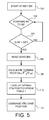
- Fig. 5 shows the flow logic for the control system set forth above.
- the requested fueling through operator control 62 is compared to maximum fueling set in logic tables in ECU 26. If the answer is that requested fueling is greater than maximum fueling at step 104, then at step 106 the sensors are read.
- turbine mass flow is calculated using any combination of sensors to estimate or determine turbine inlet temperature, turbine mass flow, and turbine inlet pressure. For example, the fresh air measurement from turbine compressor 42 and estimated fueling from the fuel system 24 could be used to calculate turbine mass flow along with direct measurement of turbine inlet temperature and pressure.
- the optimal VTG position is looked up either from the curve in Fig. 4 or the map in Fig. 3 in step 110.
- a command is issued to the variable area inlet 34 via line 60 to achieve the appropriate VTG area.
- Such a logic allows the turbine inlet area to be at a level that produces optimal power which, in turn, translates to the more rapid acceleration and response of an increase in compressor output pressure.
- the above method provides an opening that is precisely at the point at which pressure ratio and efficiency balance to achieve maximum turbine power.
Landscapes
- Engineering & Computer Science (AREA)
- Chemical & Material Sciences (AREA)
- Combustion & Propulsion (AREA)
- Mechanical Engineering (AREA)
- General Engineering & Computer Science (AREA)
- Supercharger (AREA)
- Control Of Turbines (AREA)
- Control Of Water Turbines (AREA)
- Output Control And Ontrol Of Special Type Engine (AREA)
Abstract
Description
- The invention relates to variable geometry turbochargers for internal combustion engines and, more specifically, to control schemes for such variable geometry turbines and a respective method.
- The turbocharger was first proposed by Dr. Alfred Buchi at the beginning of the Twentieth Century. The turbocharger or turbo supercharger, as otherwise known, was an advanced concept to increase the efficiency of internal combustion engine and, more specifically, compression ignition engines. The turbocharger included a turbine, driven into rotation by the otherwise wasted products of combustion from the engine, and connected to a compressor for pressurizing the inlet air to the engine for combustion to a pressure level higher than the ambient pressure. Such a system allowed greater density of the charge mixture and, therefore, greater given output for an engine so equipped. Over the years, the deficiency of the turbocharger in responding to transient operator demand increases was addressed by variable geometry turbines (VTG). In such an arrangement, the turbine inlet area is variably reduced either by a movable ring or variable inlet guide vanes to provide a lower flow area into the turbine and, therefore, a higher gas flow velocity which, in turn, acted on the turbine to increase the power to the compressor and, thus, the response to the step increase in operator demand.
- The request for increased power is complicated by the overlay of emissions regulations on the primary operational parameters of a compression ignition engine of power and efficiency. The emissions requirements generally mean that acceleration of an engine is smoke limited, that is, the fueling cannot exceed an amount relative to the available air flow that generates smoke in the form of particulates. Such a requirement alters the mechanism and control scheme for controlling the variable geometry turbine in such a way that smoke is avoided. However, such control schemes leave very much to be desired in terms of responsiveness of the variable geometry turbine in smoke limiting situations.
- Accordingly, what is needed in the art is a control system for a variable geometry turbine that maximizes responsiveness to transient increases in demand, or turbine power output.
- It is therefore the object of the present invention to comply with this need.
- This object is met according to the invention by the teaching of
claim 1, while features developing the solution in an advantageous manner are set forth in the further claims. - In one form, the invention is a method for controlling the variable geometry turbine (VTG) of a turbocharger for an operator controlled, air breathing, fuel consuming, compression ignition internal combustion engine having an operator controlled fueling rate and a maximum permissible fueling rate to produce maximum transient response. The method includes the steps of determining if operator controlled fueling rate exceeds the maximum fueling rate. The method further includes calculating the pressure ratio of the turbine as a function of the area of the VTG and calculating turbine efficiency as a function of the area of the VTG, determining the balance between pressure ratio and efficiency and commanding the VTG area as a direct function of the balance condition to achieve maximum turbine power.
- In a more specific form, the method includes the step of determining the instantaneous turbine mass flow rate (W), and determining instantaneous turbine inlet temperature (Ti), and determining turbine exit pressure (Po) to calculate the balance condition of the turbine pressure ratio and turbine efficiency.
- The above-mentioned and other features and advantages of this invention, and the manner of attaining them, will become more apparent and the invention will be better understood by reference to the following description of an embodiment of the invention taken in conjunction with the accompanying drawings, wherein:
- An embodiment of the invention described below is shown in the drawings, in which
- Fig.1
- is a schematic illustration of a work machine including an internal combustion engine embodying the present invention;
- Figs. 2A, 2B, and 2C
- represent variable geometry operating parameters as a function of the area of VTG ;
- Fig. 3
- shows a 3D representation of the relationship between VTG area and engine operating parameters;
- Fig. 4
- is one mode of operating the turbine inlet area to achieve maximum response; and
- Fig. 5
- is a flow chart of the logic diagram of the control method embodied in the present invention.
- Corresponding reference characters indicate corresponding parts throughout the several views. The exemplifications set out herein illustrate one embodiment of the invention and such exemplifications are not to be construed as limiting the scope of the invention in any manner.
- Referring now to the drawings, and more particularly to
Fig. 1 , there is shown awork machine 10 having aprime mover 12 in the form of a compression ignitioninternal combustion engine 12 providing a rotary power output throughoutput shaft 14 to apower distribution device 16 providing work functions inmachine 10 and providing ground movement throughmechanical interconnections 18 toground drive wheels 20. Thework machine 10 may have a variety of rotary load requirements affecting the need for instantaneous power increases. Such an example would be the initiation of the operation of a combine harvesting and processing operation while thework machine 10 is traversing a field. Another example may be a forestry machine, which has a saw or grappling hook instantaneously engaged to remove trees and, thus, requiring a significant increase in power output. Still another would be the imposition of an electrical load on a generator driven byinternal combustion engine 12. -
Internal combustion engine 12 is preferably a compression ignition, or diesel, engine in which the air for combustion is compressed to the point that injection of fuel produces combustion and a work output.Engine 12 has acrank case 22 in which a plurality of pistons (not shown) are reciprocally mounted and connected to a crank shaft extending to anoutput shaft 14. The pistons form combustion chambers that receive air for combustion and fuel injected via afuel system 24 into individual cylinders in appropriate quantities at appropriate times in the engine cycle produces combustion that satisfies engine output demands while meeting emissions requirements, fuel efficiency, and power output. -
Fuel system 24 may be one of a number of fuel systems, including unit injectors, in which pressure is generated at the injector, distributor pumps in which the pressure is generated elsewhere and distributed to the individual injectors, or, most recently, high pressure common rail fuel systems in which a high pressure exists in a common manifold adjacent the injector and appropriate control valves perform the function of injecting the fuel according to the control parameters. - The
fuel system 24 receives control inputs from an electronic control unit (ECU) 26 vialine 28. Althoughline 28 is illustrated as a single line, it should be noted that it may have multiple interconnections between the ECU and the fuel system and that additional engine operating parameters may be provided to theECU 26 for its control function. - When the engine completes the combustion cycle for each individual cylinder, the gaseous products are exhausted via appropriate exhaust valves to an
exhaust manifold 30 and to anexhaust line 32 to avariable area inlet 34 of aturbine 36 of aturbocharger 38.Variable area device 34, as stated previously, controls the inlet area to theturbine 36 in order to increase or decrease the velocity of the exhaust gas flow into the turbine inlet. The variable area inlet for the turbine may take the form of a series of circumferentially positioned variable inlet guide vanes positioned adjacent one another so that synchronous pivoting of the vanes produces a greater or lesser flow area of gasses directed at the turbine. Another suchvariable area inlet 34, takes the form of a moveable ring that is displaced towards and away from a fixed anular surface to control the inlet area of theturbine 36. Such a system may include slotted vanes or may be plain, as appropriate. The products of combustion that have passed acrossturbine 36 pass via anexhaust line 40 to ambient A. Although not shown, various exhaust aftertreatment devices may be included inline 40 or even inline 36, as appropriate, to filter particulates and minimize or reduce oxides of nitrogen. - The
turbocharger turbine 36 produces a rotary power output which is coupled via interconnectingshaft 40 to acompressor 42 for receiving ambient air A from aninlet line 44 for pressurization by virtue of the rotation ofcompressor 42.Inlet line 44 may have usual filtration mechanisms to ensure that the air consumed by the engine does not have harmful foreign matter. The output fromcompressor 42 passes vialine 46 to anaftercooler 48, also known as an intercooler, to cool the pressurized charge from thecompressor 42 and thus increase its density to provide additional power toengine 12. Aftercooler 48 may be an air-to-liquid type using engine coolant for the heat sink or, preferably, an air-to-air aftercooler in which the ambient air A is used to provide greater cooling. The output from aftercooler 48 passes vialine 50 to aninlet manifold 52 where the air is distributed to the engine cylinders by appropriate valve mechanisms to complete the engine cycle. - The
engine 12 may also have exhaust gas recirculation (EGR) in which avalve 54 is interposed in aline 56 interconnectingexhaust line 32 tointake line 46. The EGR is preferably cooled to minimize the reduction in charge density to theengine 12 by virtue of the heated EGR gases. - Preferably, the control of the function for the
engine 12 is integrated inECU 26. For this purpose, thefuel system 24,EGR valve 54, andvariable area inlet 34 are controlled by signal inputs from the ECU vialine 28, aline 58, andline 60, respectively. The ECU 26 also receives command inputs designated as operator command, or OC, fromdevice 62 vialine 64. Such controls may be in the form of a power lever, governor increase, accelerator pedal, or generation of additional load inputs. - Whatever the source for the increased power requirement, the
ECU 26 generates a signal to thefuel system 24 to increase fueling. In the engine system, fueling is accomplished almost instantaneously and easily exceeds the ability of theengine 12 to receive air matching the fuel without generating smoke as a result of what is known as over fueling. The maximum fueling is generally determined by selected engine operating parameters and controls the absolute level that fueling can be increased to the engine. In the past, this has resulted in attempts to crudely limit the acceleration of the turbocharger through the VTG control to accelerate or increase the power. - In accordance with the present invention, the geometry of the VTG is varied in a way that stays within emissions limits but provides increased responsiveness to the variable geometry turbine during transient conditions in smoke limited situations. This control method involves the recognition of the fact that, as shown in
Figs. 2A, 2B, and 2C , that thevariable area inlet 34 ofturbine 36, as a function of the fraction closed of thevariable area device 34, increases the pressure ratio inFig. 2A along curve 66 that shows pressure ratio increases as the area is reduced.Fig. 2B , however, shows that efficiency of theturbine 36, as a function of the fraction of area, reduces as shown by curve 68. When the pressure ratio and the efficiency balance, there is a turbine inlet area that maximizes power for a given condition of operating parameters. The condition illustrated by point 70 maximizes turbine power, which is the excess of available power for the turbine over the compressor power requirement and rotational inertia. As shown inFig2C , the variable area position for peak power may be defined by the graph 2C in which power is shown as a function of the VTG area and in which the peak power for given conditions is a maximum at about 70. It should be noted that there is not a literal intersection since pressure ratio and efficiency are in different units. Nonetheless, an optimal area can be found for the VTG. - There are a number of ways to determine optimal VTG area. One way is to use turbine maps similar to those shown in
Fig. 3 in which the Y axis shows the VTG area for peak power as a function of mass flow rate and turbo speed in rpm. This shows that the optimal VTG area to produce maximum power follows a position depending upon the flow conditions. The flow conditions are turbine mass flow rate W, turbine inlet temperature, turbo speed in rpm, and exit pressure. - Another method for determining optimal VTG area is shown in
Fig. 4 , where control of VTG area may be narrowed to a single curve in which the optimal VTG area as shown on the Y axis and the flow parameter is shown on the X axis. The flow parameter consists of the turbine mass flow rate and inlet temperature and inlet pressure. - To achieve these measurements, the system has
sensors Sensors ECU 26 bylines additional sensor 80 determines turbine exhaust pressure and is connected to theECU 26 byline 82. Anadditional sensor 84 determines turbine speed (rpm) and feeds it to theECU 26 by a line (not shown) to simplify the drawing. -
Fig. 5 shows the flow logic for the control system set forth above. Atstep 102, the requested fueling throughoperator control 62 is compared to maximum fueling set in logic tables inECU 26. If the answer is that requested fueling is greater than maximum fueling atstep 104, then atstep 106 the sensors are read. Atstep 108, turbine mass flow is calculated using any combination of sensors to estimate or determine turbine inlet temperature, turbine mass flow, and turbine inlet pressure. For example, the fresh air measurement fromturbine compressor 42 and estimated fueling from thefuel system 24 could be used to calculate turbine mass flow along with direct measurement of turbine inlet temperature and pressure. When the turbine flow is determined, the optimal VTG position is looked up either from the curve inFig. 4 or the map inFig. 3 instep 110. Instep 112, a command is issued to thevariable area inlet 34 vialine 60 to achieve the appropriate VTG area. - Such a logic allows the turbine inlet area to be at a level that produces optimal power which, in turn, translates to the more rapid acceleration and response of an increase in compressor output pressure. Unlike prior control schemes that either conservatively limit the reduction in area to an unnecessarily high opening or others that reduce the area too much, which has the unintended effect of producing less power, the above method provides an opening that is precisely at the point at which pressure ratio and efficiency balance to achieve maximum turbine power.
- While this invention has been described with respect to at least one embodiment, the present invention can be further modified within the spirit and scope of this disclosure. This application is therefore intended to cover any variations, uses, or adaptations of the invention using its general principles. Further, this application is intended to cover such departures from the present disclosure as come within known or customary practice in the art to which this invention pertains and which fall within the limits of the appended claims.
Claims (9)
- A method for controlling the variable turbine geometry (VTG) of a turbocharger (38) for an operator controlled, air breathing, fuel consuming, compression ignition, internal combustion engine (12), having an operator controlled fuel rate and a maximum permitted fueling rate, to produce maximum transience response, characterized by the steps of determining if operator controlled fueling rate exceeds the maximum permitted fueling rate; calculating the pressure ratio of said turbine (36) as a function of the area of said VTG, calculating turbine (36) efficiency as a function of the area of said VTG, determining the balance condition between pressure ratio and efficiency and commanding the VTG area as a direct function of said balance condition.
- The method according to claim 1, characterized in that the step of calculating includes determining instantaneous turbine mass flow rate (W), determining instantaneous turbine inlet temperature (Ti), determining turbine exit pressure (Po), and using such values to calculate the balance condition of said pressure ratio and turbine efficiency.
- The method according to claim 2, characterized in that a look up table is provided to determine the calculations made in claim 2.
- The method according to claim 2 or 3, characterized in that the intersection of said curves is defined by a single curve indicating VTG area as a function of a flow parameter.
- The method according to claim 4, characterized in that said flow parameter is turbine mass flow rate (W) times the square root of turbine inlet temperature over the turbine inlet pressure.
- The method according to one of the previous claims, characterized in that the engine (12) has exhaust gas recirculation (EGR) and the VGT is controlled as a part of the EGR control strategy
- The method according to one of the claims 2 - 6, characterized in by the step of estimating turbine mass flow, turbine inlet temperature and turbine inlet pressure.
- The method according to claim 7, characterized in that fresh air flow to the engine (12) is measured plus estimated fueling to calculate turbine mass flow rate (W).
- The method according to one of the previous claims, characterized in that the engine (12) powers a work machine (10) subject to step increases in power output and said method produces maximum responsiveness.
Applications Claiming Priority (1)
| Application Number | Priority Date | Filing Date | Title |
|---|---|---|---|
| US12/782,285 US8418462B2 (en) | 2010-05-18 | 2010-05-18 | Method for maximizing transient variable geometry turbine response in an internal combustion engine |
Publications (2)
| Publication Number | Publication Date |
|---|---|
| EP2388462A2 true EP2388462A2 (en) | 2011-11-23 |
| EP2388462A3 EP2388462A3 (en) | 2015-01-28 |
Family
ID=44247000
Family Applications (1)
| Application Number | Title | Priority Date | Filing Date |
|---|---|---|---|
| EP11165223.6A Withdrawn EP2388462A3 (en) | 2010-05-18 | 2011-05-09 | Method of operating a variable geometry turbine |
Country Status (3)
| Country | Link |
|---|---|
| US (1) | US8418462B2 (en) |
| EP (1) | EP2388462A3 (en) |
| CN (1) | CN102287290B (en) |
Cited By (1)
| Publication number | Priority date | Publication date | Assignee | Title |
|---|---|---|---|---|
| EP2813692A3 (en) * | 2013-06-11 | 2015-05-06 | Deere & Company | Variable geometry turbocharger control system |
Families Citing this family (2)
| Publication number | Priority date | Publication date | Assignee | Title |
|---|---|---|---|---|
| US10260405B2 (en) * | 2017-04-25 | 2019-04-16 | GM Global Technology Operations LLC | Fuel injection control of a turbocharged internal combustion engine |
| CA3119273A1 (en) | 2018-11-09 | 2020-05-14 | Iocurrents, Inc. | Machine learning-based prediction, planning, and optimization of trip time, trip cost, and/or pollutant emission during navigation |
Family Cites Families (22)
| Publication number | Priority date | Publication date | Assignee | Title |
|---|---|---|---|---|
| GB8325166D0 (en) | 1983-09-20 | 1983-10-19 | Holset Engineering Co | Variable area turbine and control system |
| US4671068A (en) | 1986-02-10 | 1987-06-09 | General Motors Corporation | Electronic control for a motor vehicle variable geometry turbocharger |
| US4928489A (en) | 1987-12-29 | 1990-05-29 | Honda Giken Kogyo K.K. | Supercharging pressure control method for turbocharged internal combustion engines |
| GB9611015D0 (en) * | 1996-05-25 | 1996-07-31 | Holset Engineering Co | Variable geometry turbocharger control |
| DE19715236B4 (en) | 1997-04-12 | 2005-03-03 | Daimlerchrysler Ag | Method for controlling the charge air mass flow of an internal combustion engine with an exhaust gas turbocharger with adjustable turbine geometry |
| US6067800A (en) | 1999-01-26 | 2000-05-30 | Ford Global Technologies, Inc. | Control method for a variable geometry turbocharger in a diesel engine having exhaust gas recirculation |
| US6357234B1 (en) * | 2000-09-21 | 2002-03-19 | Caterpillar Inc. | Turbocharger system with turbines having independently controlled variable nozzles |
| ITTO20010041A1 (en) | 2001-01-19 | 2002-07-19 | Iveco Motorenforschung Ag | CONTROL SYSTEM FOR VARIABLE GEOMETRY TURBOCHARGER. |
| ITTO20010615A1 (en) * | 2001-06-26 | 2002-12-26 | Iveco Motorenforschung Ag | ENDOTHERMAL-TURBOCHARGER ENGINE UNIT FOR A VEHICLE, IN PARTICULAR FOR AN INDUSTRIAL VEHICLE, WITH CONTROL OF THE POWER OF THE |
| LU90848B1 (en) * | 2001-10-15 | 2003-04-16 | Delphi Tchnologies Inc | Method for controlling an exhaust-gas turbocharger with a variable turbine geometry |
| US6665604B2 (en) | 2002-02-05 | 2003-12-16 | Honeywell International Inc. | Control method for variable geometry turbocharger and related system |
| JP2005299600A (en) * | 2004-04-15 | 2005-10-27 | Toyota Motor Corp | Fuel supply control device for internal combustion engine |
| DE102004051837B4 (en) * | 2004-10-25 | 2006-11-09 | Siemens Ag | Methods and apparatus for controlling and diagnosing an exhaust gas turbocharger |
| US7076954B1 (en) * | 2005-03-31 | 2006-07-18 | Caterpillar Inc. | Turbocharger system |
| FR2885388A1 (en) * | 2005-05-03 | 2006-11-10 | Renault Sas | METHOD FOR CONTROLLING A VEHICLE ENGINE COMPRISING AN ELECTRIC COMPRESSOR |
| US7296562B2 (en) * | 2006-03-30 | 2007-11-20 | Caterpiller Inc. | Control system and method for estimating turbocharger performance |
| FR2905408B1 (en) * | 2006-08-29 | 2012-02-03 | Renault Sas | CONTROL METHOD FOR SUPERCURRENT MOTOR |
| US7735320B2 (en) * | 2006-08-29 | 2010-06-15 | Gm Global Technology Operations, Inc. | Dual stage turbocharger control system |
| SE531171C2 (en) * | 2007-05-16 | 2009-01-13 | Scania Cv Abp | A method for controlling an engine with VTG turbocharger |
| US7748217B2 (en) * | 2007-10-04 | 2010-07-06 | Delphi Technologies, Inc. | System and method for modeling of turbo-charged engines and indirect measurement of turbine and waste-gate flow and turbine efficiency |
| GB2460224A (en) | 2008-05-19 | 2009-11-25 | Ford Global Tech Llc | Reducing the transient specific fuel consumption of an engine |
| CN101526042B (en) * | 2008-12-23 | 2011-07-06 | 天津大学 | Electronic control method for variable intake and exhaust system of compression ignition internal combustion engine |
-
2010
- 2010-05-18 US US12/782,285 patent/US8418462B2/en not_active Expired - Fee Related
-
2011
- 2011-04-27 CN CN201110106263.7A patent/CN102287290B/en not_active Expired - Fee Related
- 2011-05-09 EP EP11165223.6A patent/EP2388462A3/en not_active Withdrawn
Non-Patent Citations (1)
| Title |
|---|
| None |
Cited By (1)
| Publication number | Priority date | Publication date | Assignee | Title |
|---|---|---|---|---|
| EP2813692A3 (en) * | 2013-06-11 | 2015-05-06 | Deere & Company | Variable geometry turbocharger control system |
Also Published As
| Publication number | Publication date |
|---|---|
| CN102287290B (en) | 2015-08-19 |
| US8418462B2 (en) | 2013-04-16 |
| US20110283695A1 (en) | 2011-11-24 |
| CN102287290A (en) | 2011-12-21 |
| EP2388462A3 (en) | 2015-01-28 |
Similar Documents
| Publication | Publication Date | Title |
|---|---|---|
| CN108603453B (en) | Fuel limiter for once-through scavenged two-stroke cycle opposed-piston engines | |
| US9488124B2 (en) | Turbocharged engine with post fuel injection control | |
| US10054069B2 (en) | Method and apparatus for model based control of electrical boosting system | |
| US9410490B2 (en) | Fuel selection system and method for dual fuel engines | |
| CA2445184C (en) | Methods and apparatus for controlling peak firing pressure for turbo-charged diesel engines | |
| KR102242378B1 (en) | Large two-stroke uniflow scavenged gaseous fueled engine and method for controlling conditions in combustion chamber | |
| US11598249B1 (en) | Methods and systems for multi-fuel engine | |
| JP2019506561A5 (en) | ||
| US9915197B2 (en) | Control method for variable geometry exhaust turbine | |
| JP6613709B2 (en) | EGR control device | |
| WO2018081223A1 (en) | Supercharging for improved engine braking and transient performance | |
| US11421621B2 (en) | System and method for engine operation | |
| WO2014022208A1 (en) | System and method of using a turbo alternator in an exhaust gas system to generate power | |
| US8418462B2 (en) | Method for maximizing transient variable geometry turbine response in an internal combustion engine | |
| EP3880950B1 (en) | Spark ignited engine load extension with low pressure exhaust gas recirculation and delta pressure valve | |
| CN115680944B (en) | Large two-stroke turbocharged single-flow scavenged internal combustion engine and operating method thereof | |
| CN116263122A (en) | Two-stage supercharging system for engine | |
| US20250264068A1 (en) | Operating Modes for Two-Cycle Uniflow-Scavenged Diesel Engine | |
| JP7636142B2 (en) | Method and apparatus for operating an internal combustion engine with electrically assisted exhaust gas driven supercharging - Patents.com | |
| JP2019073978A (en) | Control device for diesel engine and control method | |
| JP2018076838A (en) | Control device of internal combustion engine | |
| EA042941B1 (en) | SYSTEM FOR CONTROL OF ENGINE PARAMETERS IN THE RANGE OF ENVIRONMENTAL PARAMETERS | |
| JP2018178785A (en) | diesel engine |
Legal Events
| Date | Code | Title | Description |
|---|---|---|---|
| AK | Designated contracting states |
Kind code of ref document: A2 Designated state(s): AL AT BE BG CH CY CZ DE DK EE ES FI FR GB GR HR HU IE IS IT LI LT LU LV MC MK MT NL NO PL PT RO RS SE SI SK SM TR |
|
| AX | Request for extension of the european patent |
Extension state: BA ME |
|
| PUAI | Public reference made under article 153(3) epc to a published international application that has entered the european phase |
Free format text: ORIGINAL CODE: 0009012 |
|
| PUAL | Search report despatched |
Free format text: ORIGINAL CODE: 0009013 |
|
| AK | Designated contracting states |
Kind code of ref document: A3 Designated state(s): AL AT BE BG CH CY CZ DE DK EE ES FI FR GB GR HR HU IE IS IT LI LT LU LV MC MK MT NL NO PL PT RO RS SE SI SK SM TR |
|
| AX | Request for extension of the european patent |
Extension state: BA ME |
|
| RIC1 | Information provided on ipc code assigned before grant |
Ipc: F02D 41/34 20060101ALI20141219BHEP Ipc: F02D 41/00 20060101AFI20141219BHEP |
|
| 17P | Request for examination filed |
Effective date: 20150728 |
|
| RBV | Designated contracting states (corrected) |
Designated state(s): AL AT BE BG CH CY CZ DE DK EE ES FI FR GB GR HR HU IE IS IT LI LT LU LV MC MK MT NL NO PL PT RO RS SE SI SK SM TR |
|
| STAA | Information on the status of an ep patent application or granted ep patent |
Free format text: STATUS: THE APPLICATION IS DEEMED TO BE WITHDRAWN |
|
| 18D | Application deemed to be withdrawn |
Effective date: 20150729 |