EP2388226A2 - Winding unit and yarn winding machine equipped with the same - Google Patents
Winding unit and yarn winding machine equipped with the same Download PDFInfo
- Publication number
- EP2388226A2 EP2388226A2 EP11165313A EP11165313A EP2388226A2 EP 2388226 A2 EP2388226 A2 EP 2388226A2 EP 11165313 A EP11165313 A EP 11165313A EP 11165313 A EP11165313 A EP 11165313A EP 2388226 A2 EP2388226 A2 EP 2388226A2
- Authority
- EP
- European Patent Office
- Prior art keywords
- yarn
- bobbin
- yarn feeding
- feeding bobbin
- winding
- Prior art date
- Legal status (The legal status is an assumption and is not a legal conclusion. Google has not performed a legal analysis and makes no representation as to the accuracy of the status listed.)
- Granted
Links
- 238000004804 winding Methods 0.000 title claims abstract description 185
- 238000001514 detection method Methods 0.000 claims abstract description 86
- 238000003860 storage Methods 0.000 claims description 22
- 230000004308 accommodation Effects 0.000 claims description 7
- 238000004519 manufacturing process Methods 0.000 abstract description 3
- 230000005540 biological transmission Effects 0.000 description 50
- 230000010355 oscillation Effects 0.000 description 36
- 238000000034 method Methods 0.000 description 17
- 238000012423 maintenance Methods 0.000 description 15
- 230000008569 process Effects 0.000 description 15
- 244000126211 Hericium coralloides Species 0.000 description 6
- 238000007599 discharging Methods 0.000 description 6
- 238000010586 diagram Methods 0.000 description 5
- 230000007547 defect Effects 0.000 description 4
- 230000001747 exhibiting effect Effects 0.000 description 3
- 230000005856 abnormality Effects 0.000 description 2
- 230000007246 mechanism Effects 0.000 description 2
- 230000007704 transition Effects 0.000 description 2
- 230000008859 change Effects 0.000 description 1
- 230000008878 coupling Effects 0.000 description 1
- 238000010168 coupling process Methods 0.000 description 1
- 238000005859 coupling reaction Methods 0.000 description 1
- 238000005520 cutting process Methods 0.000 description 1
- 230000000694 effects Effects 0.000 description 1
- 239000012530 fluid Substances 0.000 description 1
- 230000001788 irregular Effects 0.000 description 1
- 230000007257 malfunction Effects 0.000 description 1
- 230000002093 peripheral effect Effects 0.000 description 1
- 230000000630 rising effect Effects 0.000 description 1
- 230000032258 transport Effects 0.000 description 1
- 238000011144 upstream manufacturing Methods 0.000 description 1
Images









Classifications
-
- B—PERFORMING OPERATIONS; TRANSPORTING
- B65—CONVEYING; PACKING; STORING; HANDLING THIN OR FILAMENTARY MATERIAL
- B65H—HANDLING THIN OR FILAMENTARY MATERIAL, e.g. SHEETS, WEBS, CABLES
- B65H57/00—Guides for filamentary materials; Supports therefor
- B65H57/18—Guides for filamentary materials; Supports therefor mounted to facilitate unwinding of material from packages
-
- B—PERFORMING OPERATIONS; TRANSPORTING
- B65—CONVEYING; PACKING; STORING; HANDLING THIN OR FILAMENTARY MATERIAL
- B65H—HANDLING THIN OR FILAMENTARY MATERIAL, e.g. SHEETS, WEBS, CABLES
- B65H63/00—Warning or safety devices, e.g. automatic fault detectors, stop-motions ; Quality control of the package
-
- B—PERFORMING OPERATIONS; TRANSPORTING
- B65—CONVEYING; PACKING; STORING; HANDLING THIN OR FILAMENTARY MATERIAL
- B65H—HANDLING THIN OR FILAMENTARY MATERIAL, e.g. SHEETS, WEBS, CABLES
- B65H67/00—Replacing or removing cores, receptacles, or completed packages at paying-out, winding, or depositing stations
- B65H67/02—Arrangements for removing spent cores or receptacles and replacing by supply packages at paying-out stations
-
- B—PERFORMING OPERATIONS; TRANSPORTING
- B65—CONVEYING; PACKING; STORING; HANDLING THIN OR FILAMENTARY MATERIAL
- B65H—HANDLING THIN OR FILAMENTARY MATERIAL, e.g. SHEETS, WEBS, CABLES
- B65H69/00—Methods of, or devices for, interconnecting successive lengths of material; Knot-tying devices ;Control of the correct working of the interconnecting device
- B65H69/06—Methods of, or devices for, interconnecting successive lengths of material; Knot-tying devices ;Control of the correct working of the interconnecting device by splicing
-
- B—PERFORMING OPERATIONS; TRANSPORTING
- B65—CONVEYING; PACKING; STORING; HANDLING THIN OR FILAMENTARY MATERIAL
- B65H—HANDLING THIN OR FILAMENTARY MATERIAL, e.g. SHEETS, WEBS, CABLES
- B65H2701/00—Handled material; Storage means
- B65H2701/30—Handled filamentary material
- B65H2701/31—Textiles threads or artificial strands of filaments
Definitions
- the present invention mainly relates to a unit for winding a yarn of a yarn feeding bobbin into a package.
- a winding unit for unwinding a yarn from a yarn feeding bobbin at a yarn feeding section, and winding the yarn unwound from the yarn feeding bobbin on a winding tube at a winding section to form a winding package.
- a yarn winding machine in which a plurality of the winding units are arranged in a line.
- a magazine-type yarn winding machine is known in which a magazine is arranged in each winding unit.
- a magazine for accommodating a plurality of yarn feeding bobbins is arranged in each of the winding units, and supplies the yarn feeding bobbin to the yarn feeding section by intermittently rotating the magazine at a predetermined pitch.
- a configuration is known in which a yarn splicing device for performing yarn splicing of a yarn end from the yarn feeding bobbin and a yarn end from the winding tube when yarn cut or the like occurs is arranged in the yarn winding machine.
- Japanese Unexamined Patent Publication No. 2009-18930 discloses a yarn winding machine configured to include the yarn splicing device.
- the yarn splicing may fail for the following two causes.
- the first cause is that the yarn feeding bobbin is not accommodated in the magazine due to supply error of the operator. In this case, the yarn feeding bobbin is not supplied to the yarn feeding section even if the magazine is rotated. In such a case, the winding unit fails in yarn splicing since the yarn feeding bobbin is not supplied to the yarn feeding section.
- this first cause is referred to as an "operator cause”.
- the second cause is that the yarn feeding bobbin is supplied to the yarn feeding section but the yarn end cannot be sucked from an unwinding side end of the yarn feeding bobbin due to malfunctions of the device, and the like. In this case, the winding unit fails in yarn splicing since the end of the supplied yarn feeding bobbin cannot be sucked.
- this second cause is referred to as a "machine cause”.
- the yarn winding machine described in Japanese Unexamined Patent Publication No. 2009-18930 carries out an operation of catching the yarn end of the yarn feeding bobbin and guiding the yarn end to the yarn splicing device, and an operation of catching the yarn end from the winding tube and guiding the yarn end to the yarn splicing device even if the yarn feeding bobbin is not newly supplied. In this case, the yarn splicing cannot be carried out since the yarn from the yarn feeding bobbin cannot be caught, and hence the caught yarn from the winding tube is discarded.
- the yarn from the yarn feeding bobbin is hereinafter referred to as a "lower yarn”
- the yarn from the winding tube is hereinafter referred to as an "upper yarn”.
- the conventional winding unit wastefully consumes the yarn, and thus the manufacturing cost of the package rises. Furthermore, the package needs to be rotated at low speed to suck the yarn end in order to catch the upper yarn. However, a winding shape may be irregular if the package is rotated at low speed. The failure of yarn splicing thus becomes the cause of lowering in quality of the package.
- the present invention has been made in view of the above circumstances, and a main object thereof is to provide a winding unit in which a yarn feeding bobbin is replaced while suppressing rise in manufacturing cost and lowering in quality of a package.
- a winding unit having the following configuration.
- a winding unit includes a bobbin holding portion, a bobbin supply device, a winding section, a yarn splicing device, a bobbin presence/absence detection section, and a determination section.
- the bobbin holding portion holds a yarn feeding bobbin.
- the bobbin supply device performs a supplying operation of the yarn feeding bobbin to the bobbin holding portion.
- the winding unit performs a winding operation of winding a yarn of the yarn feeding bobbin held by the bobbin holding portion to form a package.
- the yarn splicing device performs a yarn splicing operation of splicing a yarn end of the package and a yarn end of the yarn feeding bobbin when the yarn is cut.
- the bobbin presence/absence detection section detects presence/absence of the yarn feeding bobbin at the bobbin holding portion.
- the determination section determines whether or not supply of the yarn feeding bobbin is successful based on a detection result of the bobbin presence/absence detection section after the bobbin supply device performs the supplying operation of the yarn feeding bobbin and until the yarn splicing device starts the yarn splicing operation.
- the above winding unit preferably further includes a controller for performing control to prohibit execution of the yarn splicing operation when the determination section determines that the supply of the yarn feeding bobbin is not successful.
- the yarn splicing operation is not executed if the supply failure of the yarn feeding bobbin has occurred.
- the winding unit of the present invention thus can eliminate wasteful yarn splicing operation.
- the winding unit can thereby prevent the yarn of the package from being wastefully discarded due to failure in the yarn splicing operation which inevitably occurs at the time of supply failure of the yarn feeding bobbin.
- the lowering in the quality of the package can be prevented since the package can be prevented from being turned at low speed.
- the winding unit preferably further includes a storage device for storing a determination result by the determination section.
- the winding unit of the present invention can store whether or not the supply of the yarn feeding bobbin is successful.
- the winding unit of the present invention can store whether the cause of the occurrence of the operation failure in the winding unit is due to a human error or a mechanical error when the operation failure occurs. That is, the operator can carry out a more appropriate maintenance operation with respect to the winding unit since a more accurate operation failure history can be acquired in the winding unit of the present invention.
- the human error is an error in which the supply failure of the yarn feeding bobbin to the bobbin holding portion occurs when the operator makes a mistake in supplying the yarn feeding bobbin to the winding unit.
- the mechanical error is, for example, an error in which the yarn end of the yarn feeding bobbin gets caught and cannot be taken out by the machine although the supply of the yarn feeding bobbin to the yarn feeding bobbin holding portion is successful.
- a yarn winding machine including a plurality of winding units each identical to the winding unit.
- the yarn winding machine includes a unit central management device for intensively managing the winding units.
- the unit central management device includes a storage device for storing a determination result by the determination section of the plurality of winding units.
- the winding unit of the yarn winding machine of the present invention can store whether or not the supply of the yarn feeding bobbin is successful.
- the winding unit of the present invention can store whether the cause of the occurrence of the operation failure in each winding unit is due to a human error or a mechanical error when the operation failure occurs.
- the operator can carry out a more appropriate maintenance operation with respect to the winding unit since the operation failure history of each winding unit can be referenced.
- the above winding unit preferably further includes an operation section for calculating the number of supply failures of the yarn feeding bobbin of the winding unit and the number of operation failures excluding the supply failures of the winding unit based on the determination result stored by the storage device.
- the winding unit of the present invention can calculate the number of operation failures, and the number of times the supply of the yarn feeding bobbin has failed.
- the operator can calculate the percentage of the failure caused by human error of the failures that occurred in the winding unit by referencing the operation failure history in the winding unit of the present invention. That is, in the winding unit of the present invention, the operator can determine whether or not the mechanical error occurred frequently in the winding unit by referencing the operation failure history. The operator thus can execute the maintenance operation more appropriately with respect to the winding unit.
- an operation section for calculating the number of supply failures of the yarn feeding bobbin of each of the winding units and the number of operation failures excluding the supply failures of the yarn feeding bobbin of the winding unit based on the determination result stored by the storage device is preferably arranged.
- the winding unit arranged in the yarn winding machine of the present invention can calculate the number of operation failures, and the number of times the supply of the yarn feeding bobbin has failed.
- the operator can calculate the percentage of failure caused by human error of the total number of operation failures that occurred in the winding unit by referencing the operation failure history. That is, in the winding unit of the present invention, the operator can determine whether or not the mechanical error occurred frequently in each winding unit by referencing the operation failure history, and hence can execute the maintenance operation more appropriately with respect to the winding unit.
- the above winding unit preferably further includes a display section for displaying at least one of the number of supply failures of the yarn feeding bobbin and the number of operation failures excluding the number of supply failures of the yarn feeding bobbin.
- the operator can grasp the number of supply failures of the yarn feeding bobbin by checking the display section.
- the operator thus can easily know the number of occurrences of the operation failure compared to the configuration of checking the number of occurrences of each operation failure by referencing the operation failure history. Accordingly, the operator can improve the efficiency of the maintenance operation of the winding unit.
- a display section for displaying at least one of the number of supply failures of the yarn feeding bobbin and the number of operation failures excluding the number of supply failures of the yarn feeding bobbin is preferably arranged.
- the operator can grasp the number of supply failures of the yarn feeding bobbin by checking the display section.
- the operator thus can easily know the number of occurrences of the operation failure compared to the configuration of checking the number of occurrences of each operation failure by referencing the operation failure history.
- the operator thus can improve the efficiency of the maintenance operation of the yarn winding machine.
- the above winding unit preferably has the following configuration.
- the bobbin holding portion is turned to an unwinding position for unwinding the yarn of the yarn feeding bobbin from a receiving position for receiving the yarn feeding bobbin from the bobbin supply device.
- the bobbin presence/absence detection section is arranged at a position the yarn feeding bobbin is detectable when the bobbin holding portion is at the receiving position.
- the winding unit of the present invention can determine that the supply failure of the yarn feeding bobbin occurred at an early stage after the supplying operation of the yarn feeding bobbin is executed. Therefore, for example, the winding unit of the present invention can promptly execute the processes to be executed to supply the yarn feeding bobbin to the bobbin holding portion.
- the bobbin presence/absence detection section preferably determines whether or not the supply of the yarn feeding bobbin is successful when the bobbin holding portion is at the unwinding position.
- the winding unit of the present invention detects the yarn feeding bobbin when the bobbin holding portion is at the unwinding position, a case can be prevented in which the supply of the yarn feeding bobbin is determined as successful although the supply failure of the yarn feeding bobbin has actually occurred.
- the winding unit although the supplying operation of the yarn feeding bobbin from the bobbin supply device to the bobbin holding portion is successful, the yarn feeding bobbin is sometimes disengaged from the bobbin holding portion while the bobbin holding portion is switched from the receiving position to the unwinding position. In this case as well, the winding unit of the present invention can accurately determine the failure in the supply of the yarn feeding bobbin.
- the above winding unit preferably has the following configuration.
- the winding unit includes an unwinding assisting device.
- the unwinding assisting device assists the unwinding of the yarn of the yarn feeding bobbin by moving following a chase portion which is a yarn layer end of the yarn feeding bobbin that moves with advancement of the winding operation.
- the bobbin presence/absence detection section is installed at a position the chase portion is detectable during the winding operation.
- the winding unit of the present invention can commonly use the detection section for detecting whether or not the yarn feeding bobbin is supplied to the bobbin holding portion, and the detection section for detecting the chase portion.
- the number of components thus can be reduced since the sensor for detecting the chase portion does not need to be separately arranged in the winding unit of the present invention. Therefore, the winding unit of the present invention can be compactly configured and can be manufactured at low cost.
- the above winding unit preferably further includes a notification section for notifying that supply failure of the yarn feeding bobbin has occurred.
- the controller controls the notification section so as to notify the occurrence of the supply failure of the yarn feeding bobbin when the determination section determines that the supply of the yarn feeding bobbin is not successful.
- the winding unit of the present invention can notify the operator that the supply failure of the yarn feeding bobbin has occurred.
- the operator thus can carry out the restoration operation or the like more appropriately and promptly.
- the controller preferably executes a bobbin supplying operation again when the determination section determines that the supply of the yarn feeding bobbin is not successful.
- the winding unit of the present invention thus executes the bobbin supplying operation when the supply of the yarn feeding bobbin failed.
- the winding unit of the present invention can be autonomously restored from the supply failure of the yarn feeding bobbin.
- the above winding unit preferably has the following configuration.
- a magazine in which a plurality of accommodation holes for holding a plurality of yarn feeding bobbins are arranged in a circumferential direction is arranged.
- the plurality of yarn feeding bobbins are supplied to the bobbin holding portion one at a time by intermittently driving the magazine with the controller.
- the magazine type winding unit capable of being automatically restored from the supply failure of the yarn feeding bobbin.
- the operation failure in which the yarn feeding bobbin is not supplied to the yarn feeding bobbin holding portion may occur even if the yarn feeding bobbin is actually remaining in the magazine can when the operator fails to supply the yarn feeding bobbin in the magazine can.
- the yarn feeding bobbin remaining in the magazine can may be supplied to the bobbin holding portion since the magazine can may be driven to continue the supplying operation of the yarn feeding bobbin. Therefore, the winding unit of the present invention can be restored without the restoration operation by the operator from the supply failure of the yarn feeding bobbin.
- FIG. 1 a front side of a winder unit 4 is simply referred to as the "front side” and a rear side of the winder unit 4 is simply referred to as the "rear side”.
- An automatic winder (yarn winding machine) 1 of the present embodiment includes a plurality of winder units (winding units) 4 arranged in line, and a machine control device (unit central management device) 7 arranged at one end in a direction in which the plurality of winder units 4 are arranged in line.
- Each of the winder units 4 includes a unit frame 5 arranged on one side on the left and the right when seen from the front surface, and a winding unit main body 6 arranged at the side of the unit frame 5.
- a unit controller (control section) 50 (see FIG. 3 ) for controlling each unit of the winding unit main body 6 is arranged inside the unit frame 5.
- the unit controller 50 includes a determination section 51, a storage device 52, and an operation section 53. The detailed function of each of the configurations of the unit controller 50 will be described later.
- the unit frame 5 also includes a unit input section 18 capable of inputting the setting or the like of the winding unit main body 6, and a unit display section (display section) 19 capable of displaying the state or the like of the winding operation.
- the unit input section 18 may be configured as a key or a button, for example.
- the machine control device 7 is configured to be communicable with the unit controller 50.
- the machine control device 7 thus can intensively manage the operation of the plurality of winder units 4.
- the machine control device 7 includes a machine input section 8 and a machine display section (display section) 9.
- the machine input section 8 performs various settings on each winder unit 4 such as the input of the type of yarn feeding bobbin used in the winding operation of each winder unit 4.
- the machine display section 9 is configured to be able to display the state or the like of the winding operation of each winder unit 4.
- the winder unit 4 will now be described in detail with reference to FIG. 2 and FIG. 3 .
- the winder unit 4 is a device for winding a yarn from the yarn feeding bobbin 21 around a winding bobbin 22 to form a package 29. Each portion of the winder unit 4 will be described below.
- a bobbin supply device 60 is arranged on the front side of the winder unit 4 and an operator supplies the yarn feeding bobbin 21 to this bobbin supply device 60.
- the bobbin supply device 60 includes a magazine holding portion 61, a magazine can 62, a bobbin guiding unit 64, and an open/close unit 68.
- the magazine holding portion 61 is installed towards the upward direction of the front surface from the lower part of the winder unit 4.
- the magazine can 62 is attached to the tip end of the magazine holding portion 61.
- the yarn feeding bobbin guiding unit 64 is installed at the lower side of the magazine can 62.
- a plurality of accommodation holes are formed lined to a circular form in the magazine can 62.
- the yarn feeding bobbin 21 can be set in an inclined position in each accommodation hole of the magazine can 62.
- the magazine can 62 is configured to be intermittently driven by a motor (not illustrated). When intermittently driven, the magazine can 62 moves a plurality of yarn feeding bobbins 21 set in the magazine can 62 to the yarn feeding bobbin guiding unit 64 one at a time. The moved yarn feeding bobbin 21 is then dropped to a diagonally lower side from the magazine can 62.
- the yarn feeding bobbin guiding unit 64 is configured to diagonally slide and drop the yarn feeding bobbin 21 dropped from the magazine can 62, and guide the same to a bobbin holding portion 110 of a bobbin setting section 10.
- the bobbin setting section 10 includes a discharge plate 40 and a drive portion 200, in addition to the bobbin holding portion 110.
- the discharge plate discharges the yarn feeding bobbin 21 (core tube 21a), from which unwinding of the yarn is completed.
- the drive portion 200 operates the bobbin holding portion 110 and the discharge plate 40. The details of the bobbin setting section 10 will be described later.
- the open/close unit 68 is configured by a pair of open/close members 68a, 68b that can oscillate between a near side (hereinafter referred to as front side) in FIG. 2 and a far side (hereinafter referred to as rear side) in FIG. 2 .
- the pair of open/close members 68a, 68b can switch between a closed state (state illustrated in FIG. 2 ) and an open state.
- the open/close unit 68 is closed, the inner surface of the open/close unit 68 configures one portion of the yarn feeding bobbin guiding unit 64.
- the inner surface of the open/close unit 68 comes into contact with the yarn feeding bobbin 21 dropped from the magazine can 62, and guides the yarn feeding bobbin 21 to the bobbin setting section 10 at the diagonally lower side.
- the winder unit 4 can discharge the yarn feeding bobbin 21, in which the winding is completed and the yarn is not wound, to the front side.
- a conveyor 3 (see FIG. 1 ) is installed on the front side of the open/close unit 68.
- the automatic winder 1 can convey the yarn feeding bobbin 21 discharged from the open/close unit 68 to a yarn feeding bobbin collecting box by the conveyor 3.
- the yarn feeding bobbin collecting box is not illustrated, but is arranged at the end in the conveying direction of the conveyor 3.
- the bobbin holding portion 110 is configured to oscillate to the front side and the rear side when a stepping motor 100 illustrated in FIG. 2 and FIG. 3 is driven. As illustrated in FIG. 3 , the stepping motor 100 is controlled by a stepping motor controller 102. An origin sensor 101 is attached to an appropriate position of the bobbin setting section 10. The rotation of the stepping motor 100 is controlled with the rotation state of the stepping motor 100 detected by the origin sensor 101 as a reference. A location and a member for attaching the origin sensor 101 will be described later.
- the bobbin holding portion 110 oscillates from the rear side to the front side to receive the yarn feeding bobbin 21 guided by the yarn feeding bobbin guiding unit 64.
- the bobbin holding portion 110 can set the received yarn feeding bobbin 21 in a substantially upright state by oscillating to the rear side.
- the details on the mechanism for oscillating the bobbin holding portion 110 by the drive of the stepping motor 100 and the control performed by the stepping motor controller 102 will be described later.
- the yarn 20 of the yarn feeding bobbin 21 set in the bobbin holding portion 110 of the bobbin setting section 10 is wound by a winding section 16.
- the winding section 16 includes a cradle 23 and a traverse drum 24.
- the cradle 23 is configured to be able to attach the winding bobbin 22.
- the traverse drum 24 traverses the yarn 20.
- the winding unit main body 6 includes various types of devices on a yarn traveling path between the bobbin setting section 10 and the traverse drum 24.
- the main devices of the winding unit main body 6 arranged on the yarn traveling path include a yarn kink preventer 11, an unwinding assisting device 12, a tension applying device 13, a yarn splicing device 14, and a clearer (yarn quality measuring device) 15 in this order from the bobbin setting section 10 to the traverse drum 24.
- the unwinding assisting device 12 includes a fixed member 71, a movable member 72, a raising/lowering member 73, and a chase portion detection sensor (bobbin presence/absence detection section,) 74.
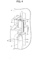
- FIG. 4 is an enlarged perspective view illustrating the configuration of the unwinding assisting device 12.
- the fixed member 71 is fixed to the unit frame 5 by way of an appropriate member.
- a throttle (not illustrated) for controlling a balloon is formed at the lower part of the fixed member 71.
- the movable member 72 is formed to a tubular shape, and is arranged to cover the outer side of the fixed member 71.
- a center axis line of the movable member 72 configured to a tubular shape and a line extended from the center axis line are referred to as a virtual line L1.
- the raising/lowering member 73 is integrally formed with the movable member 72.
- the raising/lowering member 73 is configured to be movable in the vertical direction. Therefore, the raising/lowering member 73 can be moved in the vertical direction.
- the raising/lowering member 73 includes a chase portion detection sensor 74 for detecting a chase portion 21b of the yarn feeding bobbin 21 (see FIG. 4 ).
- the chase portion 21b is a yarn layer end of the yarn feeding bobbin 21 that lowers with advancement of the winding operation. That is, the chase portion 21b lowers as the unwinding of the yarn of the yarn feeding bobbin 21 advances.
- the chase portion detection sensor 74 is a transmissive type photosensor including a light projecting portion 74a and a light receiving portion 74b. As illustrated in FIG. 3 , a detection signal detected by the chase portion detection sensor 74 is inputted to the unit controller 50.
- the winder unit 4 operates the raising/lowering member 73 based on the detection signal of the chase portion detection sensor 74.
- the winder unit 4 thus can position the movable member 72 at a predetermined distance from the chase portion 21b.
- the winder unit 4 can also cause the raising/lowering member 73 to lower following the chase portion 21b that lowers with advancement in the unwinding of the yarn feeding bobbin 21. Therefore, the winder unit 4 can always keep the distance between the chase portion 21b and the movable member 72 constant.
- the winder unit 4 can appropriately regulate the magnitude of the balloon generated at the position the yarn 20 is disengaged from the chase portion 21b when the yarn feeding bobbin 21 is being unwound, and can carry out the winding operation while maintaining the tension of the yarn unwound from the yarn feeding bobbin 21 constant.
- the unwinding side end of the yarn feeding bobbin 21 needs to be aligned with the position (unwinding standard position) on the virtual line L1 in order to perform such an appropriate unwinding assisting operation.
- the details on the control and the like for adjusting the position of the unwinding side end of the yarn feeding bobbin 21 will be described later.
- the yarn kink preventer 11 for preventing the yarn kink is arranged on the rear side of the unwinding assisting device 12.
- the kink of the yarn is a state in which the yarn curls and entangles in a spiral shape, which is one drawback that occurs in the yarn.
- the yarn kink preventer 11 includes a brush arm 11a, and a brush portion 11b formed at the tip end of the brush arm 11a.
- the brush arm 11a is configured to be turnable.
- the winder unit 4 can bring the brush portion 11b into contact with the upper end portion of the yarn feeding bobbin 21 by turning the brush arm 11a. The winder unit 4 thus can apply an appropriate tension on the yarn 20 at the time of the yarn splicing operation and the like to prevent the occurrence of yarn kinking.
- the tension applying device 13 applies a predetermined tension on the traveling yarn 20.
- the tension applying device 13 of the present embodiment is configured to a gate form in which a movable comb tooth is arranged with respect to a fixed comb tooth.
- the comb tooth on the movable side is configured to be turnable by a rotary type solenoid.
- the fixed comb tooth and the movable comb tooth are switched to the closed state or the opened state by turning the comb tooth on the movable side.
- a lower yarn detection sensor 31 is arranged between the unwinding assisting device 12 and the tension applying device 13.
- the lower yarn detection sensor 31 is configured to detect whether the yarn is traveling at the arranged position.
- the clearer 15 monitors the yarn thickness of the yarn 20 to detect a yarn defect (yarn flaw) such as slub.
- a cutter 39 is arranged on the upstream side (lower side) of the clearer 15 in the yarn path. The cutter 39 cuts the yarn 20 when the clearer 15 detects the yarn defect.
- the yarn splicing device 14 splices the lower yarn from the yarn feeding bobbin 21 and the upper yarn from the package 29.
- the yarn splicing device 14 splices the yarn after the clearer 15 detects the yarn defect and cuts the yarn by the cutter 39, after yarn cut of the yarn being unwound from the yarn feeding bobbin 21, or after replacing the yarn feeding bobbin 21.
- the yarn splicing device 14 may be a type that uses fluid such as compressed air or may be a mechanical type.
- An upper yarn guiding pipe 26 for catching and guiding the upper yarn from the package 29 is arranged on the lower side of the yarn splicing device 14.
- a lower yarn guiding pipe 25 for catching and guiding the lower yarn from the yarn feeding bobbin 21 is arranged on the upper side of the yarn splicing device 14.
- a suction hole 32 is formed at the tip end of the lower yarn guiding pipe 25.
- a suction mouth 34 is arranged at the tip end of the upper yarn guiding pipe 26.
- the lower yarn guiding pipe 25 and the upper yarn guiding pipe 26 are respectively connected to an appropriate negative pressure source to cause the suction hole 32 and the suction mouth 34 to generate a suction force.
- the suction hole 32 of the lower yarn guiding pipe 25 is turned to the lower side to suck and catch the lower yarn when replacing the yarn feeding bobbin, or the like. Thereafter, the lower yarn guiding pipe 25 is turned to the upper side with a shaft 33 as the center to guide the lower yarn to the yarn splicing device 14. Almost at the same time, the winder unit 4 turns the upper yarn guiding pipe 26 to the upper side with a shaft 35 as the center from the position of FIG. 2 and also reversely rotates the package 29. The suction mouth 34 catches the upper yarn unwound from the package 29.
- the winder unit 4 guides the upper yarn to the yarn splicing device 14 by turning the upper yarn guiding pipe 26 to the lower side with the shaft 35 as the center.
- the yarn splicing of the lower yarn and the upper yarn is then carried out in the yarn splicing device 14.
- the unit frame 5 includes a notification lamp (notification section) 56.
- the notification lamp 56 is connected to the unit controller 50 as illustrated in FIG. 3 to notify the abnormality that occurred in each unit of the winding unit main body 6 to the operator.
- the notification lamp 56 is configured to notify the occurrence of abnormality to the operator using light, but instead of such a configuration, the notification lamp 56 may be configured to notify with buzzer and the like.
- each winder unit 4 of the automatic winder 1 can wind the yarn 20 unwound from the yarn feeding bobbin 21 around the winding bobbin 22 to form the package 29 of a predetermined length.
- the bobbin setting section 10 will now be described in detail with reference to FIG. 5 to FIG. 9 .
- the bobbin setting section 10 includes the bobbin holding portion 110, the discharge plate 40, and a drive portion 200.
- the bobbin holding portion 110 holds the supplied yarn feeding bobbin 21.
- the discharge plate 40 discharges the yarn feeding bobbin 21 (core tube 21a) which unwinding of the yarn is completed.
- the drive portion 200 operates the bobbin holding portion 110 and the discharge plate 40.
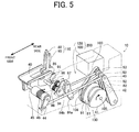
- the drive portion 200 is configured by a stepping motor 100, and a power transmission unit 120.
- the power transmission unit 120 transmits the power of the stepping motor 100 to the discharge plate 40 and the bobbin holding portion 110.
- the bobbin holding portion 110 oscillates as illustrated in FIG. 7 to FIG. 9 to change the position of the unwinding side end of the yarn feeding bobbin 21.
- the bobbin holding portion 110 is configured by a main axis member 80 and an auxiliary main axis member 90. As illustrated in FIG. 7 , the main axis member 80 and the auxiliary main axis member 90 are closed when the yarn feeding bobbin 21 is supplied so as to enter the interior of the core tube 21a.
- the bobbin holding portion 110 holds the yarn feeding bobbin 21 (see FIG. 8 ) when the auxiliary main axis member 90 oscillates in the closed state in the direction of moving away from the main axis member 80.
- the winder unit 4 oscillates the discharge plate 40 with the holding of the yarn feeding bobbin 21 by the bobbin holding portion 110 released to push out the bottom of the core tube 21a and take out the main axis member 80 and the auxiliary main axis member 90, and discharge the yarn feeding bobbin 21 (see FIG. 9 ).
- the power transmission unit 120 includes a main axis member drive cam 81, a bearing 82, an oscillation arm 83, a positioning arm 84a, a contact arm 84b, a transmission shaft 85, and a pushing spring 86, as a configuration for oscillating the main axis member 80.
- the power transmission unit 120 includes a transmission belt 103, a pulley 104, and a cam shaft 105 as a configuration for transmitting the power of the stepping motor 100 to the main axis member drive cam 81, and the like.
- the pulley 104 is fixed to the cam shaft 105, and is coupled to the output shaft of the stepping motor 100 through the transmission belt 103.
- the transmission belt 103 is simply illustrated in FIG. 5 , but is configured as a timing belt with teeth. The transmission belt 103 thus can transmit the rotation of the output shaft of the stepping motor 100 to the cam shaft 105 without slipping.
- the origin sensor 101 (not illustrated in FIG. 5 ) is attached to the pulley 104.
- the origin sensor 101 is configured to send the detection signal when the pulley 104 or the cam shaft 105 is at predetermined rotation phases.
- the rotation state when the origin sensor 101 transmits the detection signal becomes the origin of the stepping motor 100.
- the rotation control of the stepping motor 100 is carried out with such an origin as the reference.
- the main axis member drive cam 81 is fixed to the cam shaft 105.
- the main axis member drive cam 81 integrally rotates with the cam shaft 105.
- the oscillation arm 83 is arranged on the rear side than the main axis member drive cam 81.
- the rotatable bearing 82 is attached to the middle part of the oscillation arm 83. The bearing 82 is configured to rotate while coming into contact with the outer periphery of the main axis member drive cam 81.
- the tip end of the oscillation arm 83 is coupled to one end of the positioning arm 84a through a rod shaped link.
- the positioning arm 84a is supported in an oscillating manner at the appropriate position of the power transmission unit 120.
- the rotatable rotation member 87 is supported at the other end of the positioning arm 84a.
- the contact arm 84b is arranged on the front side than the positioning arm 84a.
- the tip end of the contact arm 84b is configured to come into contact with the rotation member 87.
- the rotation member 87 is attached to the positioning arm 84a.
- One end of the transmission shaft 85 is fixed to the base of the contact arm 84b.
- the other end of the transmission shaft 85 is fixed to the main axis member 80. That is, the transmission shaft 85 and the main axis member 80 are configured to cooperatively operate with each other. Therefore, the main axis member 80 integrally rotates with the contact arm 84b.
- the torsion coil spring shaped pushing spring 86 is attached to the contact arm 84b. The pushing spring 86 biases the contact arm 84b in the direction of the arrow in FIG. 5 .
- the elastic force of the pushing spring 86 acts on the contact arm 84b according to the above configuration.
- This elastic force causes the contact arm 86b to come into contact with the rotation member 87 and push the positioning arm 84a.
- the bearing 82 of the oscillation arm 83 is pushed against the main axis member drive cam 81 since the lower end of the positioning arm 84a pulls the oscillation arm 83 through the link. Therefore, the pushing spring 86 generates a spring force for bringing the main axis member drive cam 81 into contact with the bearing 82, and for bringing the contact arm 84b in contact with the positioning arm 84a.
- the power transmission unit 120 includes an auxiliary main axis member drive cam 91, a bearing 92, an oscillation arm 93, a transmission arm 94, a transmission shaft 95, and a holding spring 96 as a configuration for transmitting the power of the stepping motor 100 to the auxiliary main axis member 90.
- the auxiliary main axis member drive cam 91 is fixed to the cam shaft 105, similar to the main axis member drive cam 81.
- the oscillation arm 93 is arranged on the rear side than the auxiliary main axis member drive cam 91.
- the rotatable bearing 92 is attached to the middle part of the oscillation arm 93.
- the bearing 92 is configured to rotate while making contact with the outer periphery of the auxiliary main axis member drive cam 91.
- the tip end of the oscillation arm 93 is coupled to one end of the transmission arm 94 through a rod shaped link.
- the transmission arm 94 is supported in an oscillating manner at the appropriate position of the power transmission unit 120.
- One end of the transmission shaft 95 is attached to the base of the transmission arm 94.
- the other end of the transmission shaft 95 is fixed to the auxiliary main axis member 90. That is, the transmission shaft 95 and the auxiliary main axis member 90 are configured to cooperate with each other. Therefore, the auxiliary main axis member 90 integrally rotates with the transmission arm 94.
- a torsion coil spring shaped holding spring 96 is attached to the transmission arm 94. The holding spring 96 biases the transmission arm 94 in the direction of the dotted line arrow of FIG. 5 .
- the holding spring 96 acts the spring force in the direction the auxiliary main axis member 90 oscillates towards the rear side (direction of moving away from the main axis member 80) on the auxiliary main axis member 90 through the transmission arm 94 and the transmission shaft 95. Furthermore, the bearing 92 of the oscillation arm 93 is pushed against the auxiliary main axis member drive cam 91 since the tip end of the transmission arm 94, on which the elastic force of the holding spring 96 acts, pulls the oscillation arm 93 through the link. Therefore, the holding spring 96 generates the spring force for bringing the auxiliary main axis member drive cam 91 into contact with the bearing 92.
- the oscillation arm 93 oscillates in the direction of moving away from the cam shaft 105.
- the oscillation arm 93 pulls the end of the transmission arm 94 through the link.
- the power transmission unit 120 can oscillate the auxiliary main axis member 90 towards the front side (direction of moving closer to the main axis member 80).
- the auxiliary main axis member 90 When the auxiliary main axis member 90 is oscillated towards the front side exceeding a predetermined angle, the auxiliary main axis member 90 comes into contact with a portion (not illustrated) of the main axis member 80, and thereafter, the auxiliary main axis member 90 pushes the main axis member 80 (In this case, the tip end of the contact arm 84b and the rotation member 87 are appropriately spaced apart) . According to such a configuration, the main axis member 80 and the auxiliary main axis member 90 integrally oscillate.
- the main axis member 80 is driven by the auxiliary main axis member drive cam 91 rather than by the main axis member drive cam 81 when the auxiliary main axis member 90 is oscillated towards the front side exceeding a predetermined angle.
- the power transmission unit 120 includes a discharge plate drive cam 41, a bearing 42, an oscillation arm 43, a transmission arm 44, a transmission shaft 45, and a return spring 46 as a configuration for transmitting the power of the stepping motor 100 to the discharge plate 40.
- the discharge plate drive cam 41 is fixed to the cam shaft 105, similar to the auxiliary main axis member drive cam 91 and the main axis member drive cam 81.
- the oscillation arm 43 is arranged on the rear side than the discharge plate drive cam 41.
- the rotatable bearing 42 is attached to the middle part of the oscillation arm 43. The bearing 42 is configured to appropriately rotate while making contact with the outer periphery of the discharge plate drive cam 41.
- the tip end of the oscillation arm 43 is coupled to the transmission arm 44 through a rod shaped link.
- the transmission arm 44 supported in an oscillating manner at the appropriate position of the power transmission unit 120.
- One end of the transmission shaft 45 is attached to the base of the transmission arm 44, and the other end of the transmission shaft 45 is fixed to the discharge plate 40. That is, the transmission shaft 45 and the discharge plate 40 are configured to cooperate with each other. Therefore, the discharge plate 40 integrally oscillates with the transmission arm 44.
- the torsion coil spring shaped return spring 46 is attached to the transmission arm 44. The return spring 46 biases the transmission arm 44 in the direction of the arrow of FIG. 5 .
- the discharge plate drive cam 41, the main axis member drive cam 81, and the auxiliary main axis member drive cam 91 are configured as a cam coupling mechanism 130 fixed to the common cam shaft 105. That is, the discharge plate drive cam 41, the main axis member drive cam 81, and the auxiliary main axis member drive cam 91 are integrally driven. Furthermore, as illustrated in FIGS.
- the discharge plate drive cam 41, the main axis member drive cam 81, and the auxiliary main axis member drive cam 91 each includes a bulged portion.
- the bulged portion changes the position of the discharge plate 40, the main axis member 80, and the auxiliary main axis member 90.
- the bulged portion (holding cam operation region) of the auxiliary main axis member drive cam 91 and the bulged portion (discharge cam operation region) of the discharge plate drive cam 41 are formed to be gradual, but the bulged portion (defined cam operation region) of the main axis member drive cam 81 is formed to be slightly sharp.
- the bulged portion of the auxiliary main axis member drive cam 91 and the bulged portion of the discharge plate drive cam 41 are formed at substantially the same phase, but the bulged portion of the main axis member drive cam 81 is formed at a phase different by substantially 180° with the above bulged portions.
- the winder unit 4 appropriately drives the stepping motor 100 so that the bearing 92 of the oscillation arm 93 is in contact with the area slightly passed the peak of the bulged portion of the auxiliary main axis member drive cam 91 when receiving the yarn feeding bobbin 21. If the winder unit 4 stops the drive of the stepping motor 100 in this state, the auxiliary main axis member 90 is in a position slightly collapsed towards the front side from the upright state, as illustrated in FIG. 7 .
- the main axis member 80 also oscillates to the front side in a form of being pushed by the auxiliary main axis member 90 since the auxiliary main axis member 90 oscillates exceeding a predetermined angle.
- the position of the main axis member 80 in this state is slightly collapsed towards the front side from the upright state, similar to the auxiliary main axis member 90.
- the bobbin holding portion 110 main axis member 80 and auxiliary main axis member 90
- enters inside the core tube 21a In the present specification, the position of the main axis member 80 (position of FIG. 7 ) when receiving the yarn feeding bobbin 21 is referred to as a receiving position.
- the winder unit 4 When unwinding the yarn of the received yarn feeding bobbin 21, the winder unit 4 again drives the stepping motor 100 to rotate the cam shaft 105 in the direction indicated with the arrow in FIG. 7 .
- the bearings 42, 92 of the oscillation arms 43, 93 thereby completely pass the bulged portion of the discharge plate drive cam 41 and the auxiliary main axis member drive cam 91 and come into contact with the non-bulged portion.
- the bearing 82 of the oscillation arm 83 comes into contact with the bulged portion of the main axis member drive cam 81.
- the discharge plate 40 oscillates towards the rear side from the state of FIG. 7 and becomes horizontal, and the auxiliary main axis member 90 oscillates to slightly collapse towards the rear side.
- the main axis member 80 pushed towards the front side by the auxiliary main axis member 90 also similarly oscillates towards the rear side with the oscillation of the auxiliary main axis member 90 towards the rear side.
- the oscillation of the main axis member 80 stops as the contact arm 84b eventually comes into contact with the rotation member 87 of the positioning arm 84a.
- the auxiliary main axis member 90 oscillates towards the rear side by the spring force of the holding spring 96.
- the auxiliary main axis member 90 displaces so as to relatively move away from the main axis member 80. Therefore, the core tube 21a of the yarn feeding bobbin 21 can be held from the inner side by the bobbin holding portion 110.
- the position at which the oscillation of the main axis member 80 is stopped in this case is defined by the position of the rotation member 87 of the positioning arm 84a.
- the positioning arm 84a is coupled to the oscillation arm 83 by way of the link.
- the position of the main axis member 80 can be changed depending on which part of the bulged portion of the main axis member drive cam 81 the bearing 82 of the oscillation arm 83 is contact with (whether in contact with the rising part of the bulged portion, or in contact with the peak).
- the position of the main axis member 80 can be adjusted by changing the rotation phase of the main axis member drive cam 81. Even if the position of the main axis member 80 is changed as described above, the auxiliary main axis member 90 can maintain the holding state of the yarn feeding bobbin 21 without any problem by the elastic force of the holding spring 96.
- the position of the main axis member 80 when unwinding the yarn feeding bobbin 21 is referred to as an unwinding position.
- the origin sensor 101 detects the rotation phase of the pulley 104 in a state the main axis member 80 is in a substantially upright position as in FIG. 8 , and is set so that such state becomes the origin in the rotation control of the stepping motor 100.
- the unwinding position of the main axis member 80 changes by the type of yarn feeding bobbin 21, and the like.
- the origin detected by the origin sensor 101 and the unwinding position do not necessarily coincide.
- the stepping motor 100 is then appropriately driven to rotate the discharge plate drive cam 41, the main axis member drive cam 81, and the auxiliary main axis member drive cam 91 when discharging the yarn feeding bobbin 21.
- the bearings 42, 92 of the oscillation arms 43, 93 thereby come into contact with the bulged portion of the discharge plate drive cam 41 and the auxiliary main axis member drive cam 91. Therefore, the discharge plate 40 greatly oscillates towards the front side, as illustrated in FIG. 9 .
- the auxiliary main axis member 90 oscillates towards the front side in cooperation with the discharge plate 40 thereby releasing the holding of the yarn feeding bobbin 21, and the auxiliary main axis member 90 greatly oscillates towards the front side while pushing the main axis member 80.
- the discharge plate 40 pushes up the lower end of the core tube 21a of the yarn feeding bobbin 21, so that the winding unit 4 can discharge the yarn feeding bobbin 21.
- the position of the main axis member 80 of when discharging the yarn feeding bobbin 21 is referred to as a discharging position.
- the receiving of the yarn feeding bobbin 21, the holding of the yarn feeding bobbin 21 in the unwinding position (and adjustment of the unwinding position), and the discharging of the yarn feeding bobbin 21 can be carried out by simply driving the stepping motor 100 which is the single drive source.
- the clearer 15 may detect the yarn defect and the yarn may be cut with the cutter 39, the yarn cut of the yarn being unwound from the yarn feeding bobbin 21 may occur, or the unwinding of the yarn from the yarn feeding bobbin 21 may be completed and the yarn 20 may run out.
- the winder unit 4 monitors such yarn cut or the like (S101), and stops the winding operation when the yarn cut or the like occur (S102).
- the suction hole 32 of the lower yarn guiding pipe 25 positioned on the lower side sucks and catches the lower yarn and the upper yarn guiding pipe 26 sucks and catches the upper yarn, and yarn splicing starts (5102) .
- the unit controller 50 determines whether or not the lower yarn exists after the yarn splicing based on the detection result of the lower yarn detection sensor 31 (S103).
- the yarn splicing is completed if a yarn is remained on the yarn feeding bobbin 21 and if a mechanical error or the like does not occur. Therefore, the lower yarn is detected by the lower yarn detection sensor 31. In this case, the unit controller 50 resumes the winding of the yarn by controlling each configuration of the winding unit main body 6.
- the unit controller 50 determines that the unwinding of the yarn of the yarn feeding bobbin 21 is completed, and operates the bobbin holding portion 110 and the discharge plate 40 to perform the discharging process of the core tube 21a (S104) . Thereafter, the unit controller 50 causes the bobbin supply device 60 to newly supply the yarn feeding bobbin 21 (S105) .
- the stepping motor controller 102 drives the stepping motor 100 and moves the main axis member 80 to the receiving position in advance.
- the newly supplied yarn feeding bobbin 21 is guided to the bobbin setting section 10.
- the stepping motor controller 102 oscillates the bobbin holding portion 110 to the rear side.
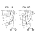
- the layout of the bobbin holding portion 110 is taken into consideration such that the yarn feeding bobbin 21 can traverse the detection range of the chase portion detection sensor 74 when oscillating the bobbin holding portion 110 to the rear side.
- the determination section 51 of the unit controller 50 determines whether or not the yarn feeding bobbin 21 is newly supplied based on the detection result of the chase portion detection sensor 74 (5106) . Specifically, if the yarn feeding bobbin 21 is detected by the chase portion detection sensor 74 after the unit controller 50 instructs to newly supply the yarn feeding bobbin 21, the determination section 51 determines that the yarn feeding bobbin 21 is newly supplied. If the yarn feeding bobbin 21 is not detected by the chase portion detection sensor 74 within a predetermined time, the determination section 51 determines that the yarn feeding bobbin 21 is not newly supplied.
- the unit controller 50 stores such a determination result in the storage device 52 arranged in the unit controller 50. The unit controller 50 then catches the yarn end of the newly supplied yarn feeding bobbin 21 and the yarn end on the package side to start the yarn splicing (S110).
- the unit controller 50 stores such a determination result in the storage device 52.
- the unit controller 50 is configured to transmit an appropriate signal to the notification lamp 56 without starting the yarn splicing operation.
- the notification lamp 56 that received the signal notifies the operator that the yarn feeding bobbin 21 is not newly supplied using a display color and the like set in advance (S107).
- the unit controller 50 of the present embodiment does not perform the catching operation of the lower yarn, the catching operation of the upper yarn, and the yarn splicing until this problem is resolved.
- the operator can know that the yarn feeding bobbin 21 is not supplied to the bobbin supply device 60 by the notification of the notification lamp 56.
- the operator can stop the notification of the notification lamp 56 by supplying the yarn feeding bobbin 21 to the bobbin supply device 60 (S108) and operating the error release button (S109). Thereafter, the bobbin supply device 60 newly performs the supply of the yarn feeding bobbin 21 by the instruction of the unit controller 50 (S105).
- the unit controller 50 When determined by the determination section 51 that the yarn feeding bobbin 21 is supplied, the unit controller 50 catches the yarn end of the newly supplied yarn feeding bobbin 21 and the yarn end from the package to start the yarn splicing (S110). The determination result of the determination section 51 here is not stored in the storage device 52.
- the catching of the upper yarn is also carried out when the catching of the lower yarn is attempted, where the caught upper yarn is ultimately discarded due to occurrence of error, thereby uselessly consuming the yarn.
- the cause of occurrence of error is due to catching mistake at a lower yarn catching unit (mechanical error) or because the yarn feeding bobbin 21 is not supplied (human error) cannot be determined on the device side.
- the catching operation of the lower yarn can be stopped at the time point the absence of the yarn feeding bobbin 21 is detected by the chase portion detection sensor 74. Therefore, the wasting of the upper yarn can be prevented. Since the presence of the yarn feeding bobbin 21 is detected with the chase portion detection sensor 74, the cause of occurrence of error can be definitely isolated.
- the time at which the mechanical error occurred, the time at which the human error occurred and the like are stored in the storage device 52 each time, so that the operation section 53 of the unit controller 50 can calculate the number of human errors in a predetermined time band, the number of mechanical errors in a predetermined time band, and the like based on the storage content.
- the calculation result can be displayed on the unit display section 19.
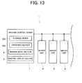
- FIG. 13 is a block diagram illustrating a modified example of the machine control device 7.
- the unit controller 50 outputs the time at which the mechanical error occurred, the time at which the human error occurred, and the like to the machine control device 7.
- the outputted times are then stored in a storage device 252 of the machine control device 7.
- an operation section 253 of the machine control device 7 calculates the number of human errors and mechanical errors in the relevant time band. The calculation result can be displayed on the machine display section 9.
- the unit controller 50 then adjusts the position of the unwinding side end of the yarn feeding bobbin 21 in parallel to the yarn splicing (S111).
- S111 the yarn splicing
- FIG. 14 is a flowchart illustrating the process of adjusting the position of the unwinding side end of the yarn feeding bobbin 21.
- the yarn feeding bobbin 21 is covered when the movable member 72 of the unwinding assisting device 12 moves, and hence the contact of the movable member 72 and the yarn feeding bobbin 21 can be reliably prevented.
- the winder unit 4 of the present embodiment can accurately position the unwinding side end of the yarn feeding bobbin 21 at the unwinding standard position.
- the winder unit 4 of the present embodiment adjusts the position of the yarn feeding bobbin 21 using the chase portion detection sensor 74 of the unwinding assisting device 12.
- the stepping motor controller 102 controls the stepping motor 100 to turn the main axis member 80 in the receiving position towards the rear side and once makes the yarn feeding bobbin 21 upright.
- the unit controller 50 brings the brush portion 11b of the yarn kink preventer 11 into contact with the upper end portion of the yarn feeding bobbin 21 (see FIG. 11B ), applies appropriate tension on the yarn 20 to prevent the yarn from kinking (S201).
- the stepping motor controller 102 oscillates the bobbin holding portion 110 so as to again slightly collapse the yarn feeding bobbin 21 towards the front side (S202) .
- the unit controller 50 stops the oscillation of the bobbin holding portion 110 when the yarn feeding bobbin 21 is detected by the chase portion detection sensor 74 (S203, FIG. 12A ).
- the storage device 52 of the unit controller 50 stores, in correspondence with the type of the yarn feeding bobbin 21 to use, that how much pulse the stepping motor 100 is to be driven from the position where the yarn feeding bobbin 21 started to be detected by the chase portion detection sensor 74 to have the yarn feeding bobbin 21 at the appropriate position (adjustment distance).
- the operator inputs the type of yarn feeding bobbin 21 to use to the unit input section 18 before starting the winding operation.
- the adjustment distance to be used in the current winding operation is thereby set in the unit controller 50.
- the unit controller 50 outputs a predetermined number of pulses to the stepping motor 100 based on the set adjustment distance, and oscillates the bobbin holding portion 110 towards the rear side (S204, FIG. 12B ).
- the unwinding side end of the yarn feeding bobbin 21 thus can be aligned with the unwinding standard position. Therefore, the contact of the movable member 72 and the yarn feeding bobbin 21 can be prevented while appropriately exhibiting the function of the unwinding assisting device 12.
- the appropriate adjustment distance can be set in the unit controller 50 by performing an appropriate input to the unit input section 18. Such input may be made to the machine input section 8 instead of to the unit input section 18. In this case, the machine control device 7 transmits the content inputted to the machine input section 8 to each winder unit 4. Thus, the appropriate adjustment distance can be collectively set with respect to the unit controller 50 of each winder unit 4.
- the winder unit 4 of the present embodiment includes the bobbin holding portion 110, the bobbin supply device 60, the winding section 16, the yarn splicing device 14, the chase portion detection sensor 74, and the determination section 51.
- the bobbin holding portion 110 holds the yarn feeding bobbin 21.
- the bobbin supply device 60 performs the supplying operation of the yarn feeding bobbin 21 to the bobbin holding portion 110 .
- the winding section 16 performs the winding operation of winding the yarn of the yarn feeding bobbin 21 held by the bobbin holding portion 110 to form a package.
- the yarn splicing device 14 performs the yarn splicing operation of yarn splicing the yarn end of the package and the yarn end of the yarn feeding bobbin 21 when the yarn is cut.
- the chase portion detection sensor 74 detects the presence of the yarn feeding bobbin 21 at the bobbin holding portion 110.
- the determination section 51 determines whether or not the supply of the yarn feeding bobbin 21 is successful based on the detection result of the chase portion detection sensor 74 after the bobbin supply device 60 performs the supplying operation of the yarn feeding bobbin 21 and until the yarn splicing device 14 starts the yarn splicing operation.
- the supply of the yarn feeding bobbin 21 to the bobbin holding portion 110 can be checked before the winder unit 4 transitions from the supplying operation to the yarn splicing operation.
- the winder unit 4 of the present embodiment includes the unit controller 50 for performing a control to prohibit the execution of the yarn splicing operation when determined by the determination section 51 that the supply of the yarn feeding bobbin 21 is not successful.
- the wasteful yarn splicing operation can be eliminated since the yarn splicing operation is not executed if the supply of the yarn feeding bobbin 21 fails. Therefore, the winder unit 4 can prevent the yarn of the package from being uselessly discarded when the yarn splicing operation fails, which inevitably occurs when the supply of the yarn feeding bobbin 21 fails. Furthermore, in the winder unit 4 of the present embodiment, the lowering of the quality of the package can be prevented since the package can be prevented from being turned at low speed.
- the winder unit 4 includes the storage device 52 for storing the determination result of the determination section 51.
- the winder unit 4 of the present embodiment can store whether or not the supply of the yarn feeding bobbin 21 is successful.
- the winder unit 4 of the present embodiment thus can store whether the cause of the occurrence of operation failure in the winder unit 4 is due to a human error in which the failure in the supply of the yarn feeding bobbin 21 to the bobbin holding portion 110 occurs when the operator makes a mistake in supplying the yarn feeding bobbin 21 to the winder unit 4, or due to a mechanical error in which the supply of the yarn feeding bobbin 21 to the yarn feeding bobbin 21 holding portion is successful but the yarn end of the yarn feeding bobbin 21 is caught and cannot be taken out by the machine. That is, in the winder unit 4 of the present embodiment, the operator can carry out a more appropriate maintenance operation with respect to the winder unit 4 since a more accurate operation failure history can be acquired.
- the automatic winder 1 of the present embodiment includes the machine control device 7 for intensively managing the winder unit 4.
- the machine control device 7 may include the storage device 252 for storing the determination results of the determination sections 51 of a plurality of winder units 4.
- the automatic winder 1 of the present embodiment can store whether or not the winder unit 4 succeeded in supplying the yarn feeding bobbin 21.
- the automatic winder 1 of the present embodiment thus can store whether the cause of the occurrence of operation failure in each winder unit 4 is due to human error or mechanical error. Therefore, in the automatic winder 1 of the present embodiment, the operator can carry out a more appropriate maintenance operation with respect to the winder unit 4 since the operation failure history of each winder unit 4 can be referenced.
- the winder unit 4 of the present embodiment includes the operation section 53 capable of calculating the number of supply failures of the yarn feeding bobbin 21 of the winder unit 4, and the number of operation failures excluding the supply failure of the winder unit 4.
- the winder unit 4 of the present embodiment thus can calculate the number of operation failures and the number of times the supply of the yarn feeding bobbin 21 has failed.
- the operator thus can calculate the percentage of the failure caused by human error of the failures that occurred in the winder unit 4 by referencing the operation failure history in the winder unit 4 of the present embodiment. That is, in the winder unit 4 of the present embodiment, the operator can determine whether or not the mechanical error occurred frequently in the winder unit 4 by referencing the operation failure history, and more appropriately execute the maintenance operation in the winder unit 4.
- the automatic winder 1 of the present embodiment can include the operation section 253 capable of calculating the number of supply failures of the yarn feeding bobbin 21 of each winder unit 4 and the number of operation failures excluding the supply failures of the yarn feeding bobbin 21 of the winder unit 4 based on the determination result stored by the storage device 252.
- the automatic winder 1 of the present embodiment can calculate the number of operation failures, and the number of times the supply of the yarn feeding bobbin 21 has failed.
- the operator can calculate the percentage of failure caused by human error of the total number of operation failures that occurred in each winder unit 4 by referencing the operation failure history. That is, in the automatic winder 1 of the present embodiment, the operator can determine whether or not the mechanical error occurred frequently in each winder unit 4 by referencing the operation failure history, and hence can execute the maintenance operation more appropriately with respect to each winder unit 4.
- the winder unit 4 of the present embodiment includes the unit display section 19 capable of displaying at least one of the number of supply failures of the yarn feeding bobbin 21 and the number of operation failures excluding the number of supply failures of the yarn feeding bobbin 21.
- the operator can know the number of supply failures of the yarn feeding bobbin 21 by checking the unit display section 19.
- the operator can easily know the number of occurrences of the operation failure compared to the configuration of checking the number of occurrences of each operation failure by referencing the operation failure history, and hence the operator can improve the efficiency of the maintenance operation of the winder unit 4.
- the automatic winder 1 of the present embodiment includes the unit display section 19 capable of displaying at least one of the number of supply failures of the yarn feeding bobbin 21 and the number of operation failures excluding the number of supply failures of the yarn feeding bobbin 21.
- the operator can know the number of supply failures of the yarn feeding bobbin 21 by checking the unit display section 19.
- the operator can easily know the number of occurrences of the operation failure compared to the configuration of checking the number of occurrences of each operation failure by referencing the operation failure history, and hence the efficiency of the maintenance operation of the automatic winder 1 can be improved.
- the winder unit 4 of the present embodiment also includes the unwinding assisting device 12 for assisting the unwinding of the yarn of the yarn feeding bobbin 21 by moving following the chase portion 21b or the yarn layer end of the yarn feeding bobbin 21 that moves with advancement of the winding operation.
- the chase portion detection sensor 74 is installed at a position capable of detecting the chase portion at the time of the winding operation to detect the presence of the yarn feeding bobbin 21.
- the winder unit 4 of the present embodiment can commonly use the detection section for detecting whether or not the yarn feeding bobbin 21 is supplied to the bobbin holding portion 110, and the detection section for detecting the chase portion 21b.
- the number of components thus can be reduced since the sensor for detecting the chase portion does not need to be additionally arranged in the winder unit 4 of the present embodiment. Therefore, the winder unit 4 of the present embodiment can be compactly configured and can be manufactured at low cost.
- the winder unit 4 of the present embodiment includes the notification lamp 56 for notifying that the supply failure of the yarn feeding bobbin 21 has occurred when determined by the determination section 51 that the supply of the yarn feeding bobbin 21 is not successful.
- the winder unit 4 of the present embodiment can notify the operator that the supply failure of the yarn feeding bobbin 21 has occurred, and hence a restoration operation or the like can be carried out more appropriately and more promptly.
- the bobbin supplying operation is again executed when determined by the determination section 51 that the supply of the yarn feeding bobbin 21 is not successful.
- the winder unit 4 of the present embodiment executes the bobbin supplying operation when the supply of the yarn feeding bobbin 21 failed.
- the winder unit 4 of the present embodiment thus can be autonomously restored from the supply failure of the yarn feeding bobbin 21.
- the winder unit 4 of the present embodiment includes the magazine can 62 in which a plurality of accommodation holes capable of holding the yarn feeding bobbin 21 are arranged in the circumferential direction. A plurality of yarn feeding bobbins 21 are supplied to the bobbin holding portion 110 one at a time by intermittently driving the magazine with the unit controller 50.
- the operation failure in which the yarn feeding bobbin 21 is not supplied to the yarn feeding bobbin 21 holding portion when the yarn feeding bobbin 21 is actually remaining in the magazine can 62 occurs when the operator fails to supply the yarn feeding bobbin 21 in the magazine can 62.
- the winder unit 4 of the present embodiment thus can be automatically restored from such an operation failure.
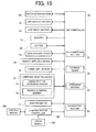
- FIG. 15 is a block diagram illustrating the main configuration of the winder unit 4 according to the first variant and a second variant.
- FIG. 16 is a flowchart illustrating the process of adjusting the position of the unwinding side end of the yarn feeding bobbin 21 according to the first variant.
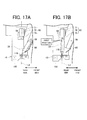
- FIGS. 17A and 17B are side views illustrating the first half of the state in which the position of the unwinding side end of the yarn feeding bobbin 21 is adjusted according to the first variant.
- FIGS. 18A and 18B are side views illustrating the last half of the state in which the position of the unwinding side end of the yarn feeding bobbin 21 is adjusted according to the first variant.
- the same reference numerals are denoted for the members same as or similar to the embodiment described above, and the description thereof may be omitted.
- the illustration of the yarn kink preventer 11 and the chase portion detection sensor 74 is omitted to simplify the surrounding of the yarn feeding bobbin 21.
- the unit controller 50 of the winder unit 4 of the present variant has a configuration including a calculation section 54 as illustrated in FIG. 15 . The process of adjusting the unwinding side end of the yarn feeding bobbin 21 will be specifically described below.
- the yarn feeding bobbin 21 enters the detection range of the bobbin detection sensor 58 (see FIG. 17A ) when the yarn feeding bobbin 21 is newly supplied (5301) .
- the determination section 51 of the unit controller 50 determines whether or not the yarn feeding bobbin 21 is newly supplied based on the detection result of the bobbin detection sensor 58 (5302).
- the method of determining whether or not the yarn feeding bobbin 21 is newly supplied and the control performed by the unit controller 50 after the presence or absence of the yarn feeding bobbin 21 is determined are carried out similar to the embodiment described above.
- the unit controller 50 drives the stepping motor 100 to oscillate the bobbin holding portion 110 towards the rear side before and after the determination by the determination section 51 on whether or not the yarn feeding bobbin 21 is newly supplied (S303).
- the unwinding side end of the yarn feeding bobbin 21 is detected by the position detection sensor 59 (see FIG. 17B ) .
- the position detection sensor 59 has a linear detection range, which detection range is arranged to intersect the virtual line L1 described above.
- the calculation section 54 of the unit controller 50 calculates the number of pulses from the origin at the position (first position) of the moment the unwinding side end of the yarn feeding bobbin 21 is detected by the position detection sensor 59 (S304).
- the calculation section 54 calculates the number of pulses from the origin at the position (second position) of the moment the unwinding side end of the yarn feeding bobbin 21 is no longer detected by the position detection sensor 59 (S305). Thereafter, the calculation section 54 calculates the number of pulses from the origin at a third position which is an intermediate position between the first position and the second position (S306).
- the stepping motor controller 102 then drives the stepping motor 100 based on the calculated number of pulses at the third position, and oscillates the bobbin holding portion 110 towards the front side (S307, FIG. 18B ).
- the unwinding side end of the yarn feeding bobbin 21 thus can be aligned with the unwinding standard position. Therefore, the contact of the movable member 72 and the yarn feeding bobbin 21 can be prevented while appropriately exhibiting the function of the unwinding assisting device 12.
- the intermediate position can be considered as a position that divides the space between the first position and the second position in half, but the present invention is not limited thereto, and various positions can be adopted according to the layout. Furthermore, the count of the number of pulses can be obtained by counting the pulses that the stepping motor controller 102 outputs to the stepping motor 100.
- the first position, the second position, and the third position are calculated in the first variant, but the following method may be used instead. That is, the first position is calculated, and the pulse that the stepping motor controller 102 outputs to the stepping motor 100 is counted until the moment the unwinding side end of the yarn feeding bobbin 21 is no longer detected from the first position. Then, the bobbin holding portion 110 may be returned (turned towards the front side) by the distance corresponding to half of the counted number of pulses to perform alignment.
- the winder unit 4 of the first variant has the following configuration. That is, the bobbin holding portion 110 is turned from the receiving position for receiving the yarn feeding bobbin 21 from the bobbin supply device 60 to the unwinding position for unwinding the yarn of the yarn feeding bobbin 21.
- the bobbin detection sensor 58 is arranged at a position the yarn feeding bobbin 21 can be detected when the bobbin holding portion 110 is at the receiving position.
- the winder unit 4 of the first variant thus can determine that the supply failure of the yarn feeding bobbin 21 has occurred at an early stage after the supplying operation of the yarn feeding bobbin 21 is executed. Therefore, the winder unit 4 of the first variant can promptly execute the processes to be executed to supply the yarn feeding bobbin 21 to the bobbin holding portion 110.
- whether or not the supply of the yarn feeding bobbin 21 is successful can be determined when the bobbin holding portion 110 is at the unwinding position by changing the position of the bobbin detection sensor 58.
- the winder unit 4 of the first variant thus detects the yarn feeding bobbin 21 when the bobbin holding portion 110 is at the unwinding position, so that a case can be prevented in which the supply of the yarn feeding bobbin 21 is determined as successful although the supply failure of the yarn feeding bobbin 21 actually occurred.
- the failure in the supply of the yarn feeding bobbin 21 can be accurately determined even when the yarn feeding bobbin 21 is disengaged from the bobbin holding portion 110 while the bobbin holding portion 110 is switched from the receiving position to the unwinding position although the supplying operation of the yarn feeding bobbin 21 from the bobbin supply device 60 to the bobbin holding portion 110 is successful.
- FIG. 19 is a flowchart illustrating the process of adjusting the position of the unwinding side end of the yarn feeding bobbin 21 according to the second variant.
- FIGS. 20A and 20B are side views illustrating the first half of the state in which the position of the unwinding side end of the yarn feeding bobbin 21 is adjusted according to the second variant.
- FIGS. 21A and 21B are side views illustrating the last half of the state in which the position of the unwinding side end of the yarn feeding bobbin 21 is adjusted according to the second variant.
- the same reference numerals are denoted for the members same as or similar to the embodiment described above, and the description thereof may be omitted.
- the illustration of the yarn kink preventer 11 is omitted to simplify the surrounding of the yarn feeding bobbin 21.
- the winder unit 4 of the present variant also includes the calculation section 54 as illustrated in FIG. 15 .
- the position of the unwinding side end of the yarn feeding bobbin 21 is adjusted using the chase portion detection sensor 74. The process of adjusting the position of the unwinding side end of the yarn feeding bobbin 21 will be specifically described below.
- the unit controller 50 oscillates the bobbin holding portion 110 towards the rear side (S402) .
- the calculation section 54 calculates the number of pulses from the origin at the position (first position, FIG. 20B ) where the unwinding side end of the yarn feeding bobbin 21 starts to be detected by the chase portion detection sensor 74 (S403).
- the yarn feeding bobbin 21 is then further oscillated towards the rear side, and the number of pulses from the origin at the position (second position, FIG. 21A ) where the yarn feeding bobbin 21 is no longer detected by the chase portion detection sensor 74 is calculated (S404) .
- the calculation section 54 then calculates the number of pulses from the origin at the third position which is the intermediate position between the first position and the second position (S405).
- the stepping motor controller 102 thereafter calculates the final adjustment distance based on the third position and the adjustment distance set based on the storage content of the storage device 52 (S406) .
- the number of pulses to be outputted to the stepping motor 100 is then determined based on the final adjustment distance.
- the stepping motor controller 102 drives the stepping motor 100 by the determined number of pulses, thereby rotating the bobbin holding portion 110 towards the rear side (S407, FIG. 21B ).
- the winder unit 4 of the second variant can align the unwinding side end of the yarn feeding bobbin 21 with the unwinding standard position. Therefore, the movable member 72 can be prevented from being brought into contact with the yarn feeding bobbin 21 while appropriately exhibiting the functions of the unwinding assisting device 12.
- the tubular movable member 72 is used in the unwinding assisting device 12, but instead, the movable member 72 of various shapes such as a linear guide member or a polygonal column member molded with a plate member having a guide hole, a wire, or the like may be used.
- the unwinding standard position is set with the unwinding assisting device 12 as the basis, but the unwinding standard position merely needs to be a target position set in advance, and the member that becomes the basis in the setting of the unwinding standard position is not limited to the unwinding assisting device 12.
- consideration is made in setting the unwinding standard position in the winder unit 4 of a type in which the unwinding assisting device 12 is not arranged.
- the unwinding standard position may be a position on the extended line of the center position where the yarn 20 is traversed with respect to the winding bobbin 22, or a position on the vertical line of the guide member for guiding the yarn unwound from the yarn feeding bobbin 21.
- the configuration in which the discharge plate 40, the bobbin holding portion 110, and the like are driven using the stepping motor 100 is adopted, but instead, a configuration in which the power transmission unit 120 is driven using a servo motor, a linear motor, a voice coil motor, or the like may be adopted.
- a transmissive type photosensor is used for the chase portion detection sensor 74, the position detection sensor 59, and the bobbin detection sensor 58, but instead, a reflection type photosensor and the like may be used. Furthermore, instead of the configuration of detecting the yarn feeding bobbin 21 with the sensor, a configuration of detecting the movement or the state of the chase portion of the yarn feeding bobbin 21 by detecting the yarn feeding bobbin 21 as an image by a camera may be adopted.
- a gate type tension applying device is used for the tension applying device 13, but instead, a configuration in which a predetermined tension is applied on the traveling yarn using the known disc type tension applying device may be adopted.
- a pulse for controlling the stepping motor 100 is used in the position detection of the bobbin holding portion 110, but the position detection may be carried out by feedback controlling the servo motor.
- the angle of the bobbin holding portion 110 may be detected using an angular sensor.
- the bobbin supply device 60 including the magazine can 62 is described, but the bobbin supply device 60 is not limited to such a configuration as long as it supplies the yarn feeding bobbin 21 to a predetermined position where the yarn 20 is unwound.
- a configuration including a columnar accommodation member capable of accommodating a plurality of yarn feeding bobbins 21 in a stacked manner to supply the yarn feeding bobbin 21 from the accommodation member may be adopted.
- the bobbin supply device 60 including the magazine can 62 is described, but the configuration of the bobbin supply device 60 is not limited thereto.
- the bobbin supply device 60 may be a yarn feeding bobbin supply device 60 of a tray type that transports the tray on which the yarn feeding bobbin 21 is stacked with a conveyor belt to supply to the unwinding position.
- the position of the unwinding side end of the yarn feeding bobbin 21 may be moved in the front and back direction by switching the transporting direction of the conveyor to align the position of the unwinding side end of the yarn feeding bobbin 21 with the target position.
- an oscillation member for oscillating the tray may be arranged at the unwinding position, and the yarn feeding bobbin 21 may be oscillated at the unwinding position to align the position of the unwinding side end of the yarn feeding bobbin 21 with the target position.
Landscapes
- Engineering & Computer Science (AREA)
- Quality & Reliability (AREA)
- Replacing, Conveying, And Pick-Finding For Filamentary Materials (AREA)
- Unwinding Of Filamentary Materials (AREA)
Abstract
Description
- The present invention mainly relates to a unit for winding a yarn of a yarn feeding bobbin into a package.
- There is known a winding unit for unwinding a yarn from a yarn feeding bobbin at a yarn feeding section, and winding the yarn unwound from the yarn feeding bobbin on a winding tube at a winding section to form a winding package. There is also known a yarn winding machine in which a plurality of the winding units are arranged in a line. As one type of such yarn winding machine, a magazine-type yarn winding machine is known in which a magazine is arranged in each winding unit. In the magazine-type yarn winding machine, a magazine for accommodating a plurality of yarn feeding bobbins is arranged in each of the winding units, and supplies the yarn feeding bobbin to the yarn feeding section by intermittently rotating the magazine at a predetermined pitch. A configuration is known in which a yarn splicing device for performing yarn splicing of a yarn end from the yarn feeding bobbin and a yarn end from the winding tube when yarn cut or the like occurs is arranged in the yarn winding machine. Japanese Unexamined Patent Publication No.
2009-18930 - In the yarn winding machine disclosed in Japanese Unexamined Patent Publication No.
2009-18930 - The yarn splicing may fail for the following two causes. The first cause is that the yarn feeding bobbin is not accommodated in the magazine due to supply error of the operator. In this case, the yarn feeding bobbin is not supplied to the yarn feeding section even if the magazine is rotated. In such a case, the winding unit fails in yarn splicing since the yarn feeding bobbin is not supplied to the yarn feeding section. Hereinafter, this first cause is referred to as an "operator cause". The second cause is that the yarn feeding bobbin is supplied to the yarn feeding section but the yarn end cannot be sucked from an unwinding side end of the yarn feeding bobbin due to malfunctions of the device, and the like. In this case, the winding unit fails in yarn splicing since the end of the supplied yarn feeding bobbin cannot be sucked. Hereinafter, this second cause is referred to as a "machine cause".
- However, in the conventional winding unit described in Japanese Unexamined Patent Publication No.
2009-18930 2009-18930 - The yarn winding machine described in Japanese Unexamined Patent Publication No.
2009-18930 - That is, the conventional winding unit wastefully consumes the yarn, and thus the manufacturing cost of the package rises. Furthermore, the package needs to be rotated at low speed to suck the yarn end in order to catch the upper yarn. However, a winding shape may be irregular if the package is rotated at low speed. The failure of yarn splicing thus becomes the cause of lowering in quality of the package.
- The present invention has been made in view of the above circumstances, and a main object thereof is to provide a winding unit in which a yarn feeding bobbin is replaced while suppressing rise in manufacturing cost and lowering in quality of a package.
- According to a first aspect of the present invention, a winding unit having the following configuration is provided. In other words, a winding unit includes a bobbin holding portion, a bobbin supply device, a winding section, a yarn splicing device, a bobbin presence/absence detection section, and a determination section. The bobbin holding portion holds a yarn feeding bobbin. The bobbin supply device performs a supplying operation of the yarn feeding bobbin to the bobbin holding portion. The winding unit performs a winding operation of winding a yarn of the yarn feeding bobbin held by the bobbin holding portion to form a package. The yarn splicing device performs a yarn splicing operation of splicing a yarn end of the package and a yarn end of the yarn feeding bobbin when the yarn is cut. The bobbin presence/absence detection section detects presence/absence of the yarn feeding bobbin at the bobbin holding portion. The determination section determines whether or not supply of the yarn feeding bobbin is successful based on a detection result of the bobbin presence/absence detection section after the bobbin supply device performs the supplying operation of the yarn feeding bobbin and until the yarn splicing device starts the yarn splicing operation.
- Therefore, in the winding unit of the present invention, whether or not the yarn feeding bobbin is supplied to the bobbin holding portion can be determined before the winding unit transitions from the supplying operation to the yarn splicing operation.
- The above winding unit preferably further includes a controller for performing control to prohibit execution of the yarn splicing operation when the determination section determines that the supply of the yarn feeding bobbin is not successful.
- Therefore, in the winding unit of the present invention, the yarn splicing operation is not executed if the supply failure of the yarn feeding bobbin has occurred. The winding unit of the present invention thus can eliminate wasteful yarn splicing operation. The winding unit can thereby prevent the yarn of the package from being wastefully discarded due to failure in the yarn splicing operation which inevitably occurs at the time of supply failure of the yarn feeding bobbin. Furthermore, in the winding unit of the present invention, the lowering in the quality of the package can be prevented since the package can be prevented from being turned at low speed.
- In the above winding unit, the winding unit preferably further includes a storage device for storing a determination result by the determination section.
- Therefore, the winding unit of the present invention can store whether or not the supply of the yarn feeding bobbin is successful. Thus, for example, the winding unit of the present invention can store whether the cause of the occurrence of the operation failure in the winding unit is due to a human error or a mechanical error when the operation failure occurs. That is, the operator can carry out a more appropriate maintenance operation with respect to the winding unit since a more accurate operation failure history can be acquired in the winding unit of the present invention. The human error is an error in which the supply failure of the yarn feeding bobbin to the bobbin holding portion occurs when the operator makes a mistake in supplying the yarn feeding bobbin to the winding unit. The mechanical error is, for example, an error in which the yarn end of the yarn feeding bobbin gets caught and cannot be taken out by the machine although the supply of the yarn feeding bobbin to the yarn feeding bobbin holding portion is successful.
- According to a second aspect of the present invention, there is provided a yarn winding machine including a plurality of winding units each identical to the winding unit. In other words, the yarn winding machine includes a unit central management device for intensively managing the winding units. The unit central management device includes a storage device for storing a determination result by the determination section of the plurality of winding units.
- Therefore, the winding unit of the yarn winding machine of the present invention can store whether or not the supply of the yarn feeding bobbin is successful. Thus, for example, the winding unit of the present invention can store whether the cause of the occurrence of the operation failure in each winding unit is due to a human error or a mechanical error when the operation failure occurs. In the yarn winding machine of the present invention, the operator can carry out a more appropriate maintenance operation with respect to the winding unit since the operation failure history of each winding unit can be referenced.
- The above winding unit preferably further includes an operation section for calculating the number of supply failures of the yarn feeding bobbin of the winding unit and the number of operation failures excluding the supply failures of the winding unit based on the determination result stored by the storage device.
- Therefore, the winding unit of the present invention can calculate the number of operation failures, and the number of times the supply of the yarn feeding bobbin has failed. Thus, for example, the operator can calculate the percentage of the failure caused by human error of the failures that occurred in the winding unit by referencing the operation failure history in the winding unit of the present invention. That is, in the winding unit of the present invention, the operator can determine whether or not the mechanical error occurred frequently in the winding unit by referencing the operation failure history. The operator thus can execute the maintenance operation more appropriately with respect to the winding unit.
- In the above yarn winding machine, an operation section for calculating the number of supply failures of the yarn feeding bobbin of each of the winding units and the number of operation failures excluding the supply failures of the yarn feeding bobbin of the winding unit based on the determination result stored by the storage device is preferably arranged.
- Therefore, the winding unit arranged in the yarn winding machine of the present invention can calculate the number of operation failures, and the number of times the supply of the yarn feeding bobbin has failed. Thus, for example, in the winding unit of the yarn winding machine of the present invention, the operator can calculate the percentage of failure caused by human error of the total number of operation failures that occurred in the winding unit by referencing the operation failure history. That is, in the winding unit of the present invention, the operator can determine whether or not the mechanical error occurred frequently in each winding unit by referencing the operation failure history, and hence can execute the maintenance operation more appropriately with respect to the winding unit.
- The above winding unit preferably further includes a display section for displaying at least one of the number of supply failures of the yarn feeding bobbin and the number of operation failures excluding the number of supply failures of the yarn feeding bobbin.
- Therefore, in the winding unit of the present invention, the operator can grasp the number of supply failures of the yarn feeding bobbin by checking the display section. The operator thus can easily know the number of occurrences of the operation failure compared to the configuration of checking the number of occurrences of each operation failure by referencing the operation failure history. Accordingly, the operator can improve the efficiency of the maintenance operation of the winding unit.
- In the above yarn winding machine, a display section for displaying at least one of the number of supply failures of the yarn feeding bobbin and the number of operation failures excluding the number of supply failures of the yarn feeding bobbin is preferably arranged.
- Therefore, in the yarn winding machine of the present invention, the operator can grasp the number of supply failures of the yarn feeding bobbin by checking the display section. The operator thus can easily know the number of occurrences of the operation failure compared to the configuration of checking the number of occurrences of each operation failure by referencing the operation failure history. The operator thus can improve the efficiency of the maintenance operation of the yarn winding machine.
- The above winding unit preferably has the following configuration. In other words, the bobbin holding portion is turned to an unwinding position for unwinding the yarn of the yarn feeding bobbin from a receiving position for receiving the yarn feeding bobbin from the bobbin supply device. The bobbin presence/absence detection section is arranged at a position the yarn feeding bobbin is detectable when the bobbin holding portion is at the receiving position.
- Therefore, the winding unit of the present invention can determine that the supply failure of the yarn feeding bobbin occurred at an early stage after the supplying operation of the yarn feeding bobbin is executed. Therefore, for example, the winding unit of the present invention can promptly execute the processes to be executed to supply the yarn feeding bobbin to the bobbin holding portion.
- In the above winding unit, the bobbin presence/absence detection section preferably determines whether or not the supply of the yarn feeding bobbin is successful when the bobbin holding portion is at the unwinding position.
- Therefore, since the winding unit of the present invention detects the yarn feeding bobbin when the bobbin holding portion is at the unwinding position, a case can be prevented in which the supply of the yarn feeding bobbin is determined as successful although the supply failure of the yarn feeding bobbin has actually occurred. In the winding unit, although the supplying operation of the yarn feeding bobbin from the bobbin supply device to the bobbin holding portion is successful, the yarn feeding bobbin is sometimes disengaged from the bobbin holding portion while the bobbin holding portion is switched from the receiving position to the unwinding position. In this case as well, the winding unit of the present invention can accurately determine the failure in the supply of the yarn feeding bobbin.
- The above winding unit preferably has the following configuration. In other words, the winding unit includes an unwinding assisting device. The unwinding assisting device assists the unwinding of the yarn of the yarn feeding bobbin by moving following a chase portion which is a yarn layer end of the yarn feeding bobbin that moves with advancement of the winding operation. The bobbin presence/absence detection section is installed at a position the chase portion is detectable during the winding operation.
- The winding unit of the present invention can commonly use the detection section for detecting whether or not the yarn feeding bobbin is supplied to the bobbin holding portion, and the detection section for detecting the chase portion. The number of components thus can be reduced since the sensor for detecting the chase portion does not need to be separately arranged in the winding unit of the present invention. Therefore, the winding unit of the present invention can be compactly configured and can be manufactured at low cost.
- The above winding unit preferably further includes a notification section for notifying that supply failure of the yarn feeding bobbin has occurred. The controller controls the notification section so as to notify the occurrence of the supply failure of the yarn feeding bobbin when the determination section determines that the supply of the yarn feeding bobbin is not successful.
- Therefore, the winding unit of the present invention can notify the operator that the supply failure of the yarn feeding bobbin has occurred. The operator thus can carry out the restoration operation or the like more appropriately and promptly.
- In the above winding unit, the controller preferably executes a bobbin supplying operation again when the determination section determines that the supply of the yarn feeding bobbin is not successful.
- The winding unit of the present invention thus executes the bobbin supplying operation when the supply of the yarn feeding bobbin failed. Thus, for example, the winding unit of the present invention can be autonomously restored from the supply failure of the yarn feeding bobbin.
- The above winding unit preferably has the following configuration. In other words, a magazine can in which a plurality of accommodation holes for holding a plurality of yarn feeding bobbins are arranged in a circumferential direction is arranged. The plurality of yarn feeding bobbins are supplied to the bobbin holding portion one at a time by intermittently driving the magazine with the controller.
- In this manner, there is provided the magazine type winding unit capable of being automatically restored from the supply failure of the yarn feeding bobbin. In the magazine type winding unit, the operation failure in which the yarn feeding bobbin is not supplied to the yarn feeding bobbin holding portion may occur even if the yarn feeding bobbin is actually remaining in the magazine can when the operator fails to supply the yarn feeding bobbin in the magazine can. However, in the winding unit of the present invention, the yarn feeding bobbin remaining in the magazine can may be supplied to the bobbin holding portion since the magazine can may be driven to continue the supplying operation of the yarn feeding bobbin. Therefore, the winding unit of the present invention can be restored without the restoration operation by the operator from the supply failure of the yarn feeding bobbin.
-
-
FIG. 1 is an outer appearance perspective view illustrating an overall configuration of an automatic winder according to one embodiment of the present invention; -
FIG. 2 is a schematic side view of the winder unit; -
FIG. 3 is a block diagram illustrating a main configuration of the winder unit; -
FIG. 4 is an enlarged perspective view illustrating a configuration of an unwinding assisting device; -
FIG. 5 is a perspective view illustrating a configuration of a bobbin setting section; -
FIGS. 6A to 6C are side views illustrating a shape of a cam arranged in a power transmission unit; -
FIG. 7 is a side view illustrating a configuration of an adjustment unit when a main axis member is in a receiving position; -
FIG. 8 is a side view illustrating a configuration of the adjustment unit when the main axis member is in an unwinding position; -
FIG. 9 is a side view illustrating a configuration of the adjustment unit when the main axis member is in a discharging position; -
FIG. 10 is a flowchart illustrating a process performed by the winder unit when yarn cut or the like occurs; -
FIGS. 11A and 11B are side views illustrating a first half of a state in which a position of an unwinding side end of the yarn feeding bobbin is adjusted; -
FIGS. 12A and 12B are side views illustrating a last half of the state in which the position of the unwinding side end of the yarn feeding bobbin is adjusted; -
FIG. 13 is a block diagram illustrating a modified example of a machine control device; -
FIG. 14 is a flowchart illustrating a process of adjusting the position of the unwinding side end of the yarn feeding bobbin; -
FIG. 15 is a block diagram illustrating the main configuration of the winder unit according to a first variant and a second variant; -
FIG. 16 is a flowchart illustrating a process of adjusting the position of the unwinding side end of the yarn feeding bobbin according to the first variant; -
FIGS. 17A and 17B are side views illustrating the first half of the state in which the position of the unwinding side end of the yarn feeding bobbin is adjusted according to the first variant; -
FIGS. 18A and 18B are side views illustrating the last half of the state in which the position of the unwinding side end of the yarn feeding bobbin is adjusted according to the first variant; -
FIG. 19 is a flowchart illustrating a process of adjusting the position of the unwinding side end of the yarn feeding bobbin according to the second variant; -
FIGS. 20A and 20B are side views illustrating the first half of the state in which the position of the unwinding side end of the yarn feeding bobbin is adjusted according to the second variant; and -
FIGS. 21A and 21B are side views illustrating the last half of the state in which the position of the unwinding side end of the yarn feeding bobbin is adjusted according to the second variant. - Embodiments of the present invention will be described with reference to the drawings. First, an overview of an
automatic winder 1 of the present embodiment will be described with reference toFIG. 1 . In the following description, a front side of awinder unit 4 is simply referred to as the "front side" and a rear side of thewinder unit 4 is simply referred to as the "rear side". - An automatic winder (yarn winding machine) 1 of the present embodiment includes a plurality of winder units (winding units) 4 arranged in line, and a machine control device (unit central management device) 7 arranged at one end in a direction in which the plurality of
winder units 4 are arranged in line. - Each of the
winder units 4 includes aunit frame 5 arranged on one side on the left and the right when seen from the front surface, and a winding unitmain body 6 arranged at the side of theunit frame 5. A unit controller (control section) 50 (seeFIG. 3 ) for controlling each unit of the winding unitmain body 6 is arranged inside theunit frame 5. Theunit controller 50 includes adetermination section 51, astorage device 52, and anoperation section 53. The detailed function of each of the configurations of theunit controller 50 will be described later. Theunit frame 5 also includes aunit input section 18 capable of inputting the setting or the like of the winding unitmain body 6, and a unit display section (display section) 19 capable of displaying the state or the like of the winding operation. Theunit input section 18 may be configured as a key or a button, for example. - The
machine control device 7 is configured to be communicable with theunit controller 50. Themachine control device 7 thus can intensively manage the operation of the plurality ofwinder units 4. Themachine control device 7 includes amachine input section 8 and a machine display section (display section) 9. Themachine input section 8 performs various settings on eachwinder unit 4 such as the input of the type of yarn feeding bobbin used in the winding operation of eachwinder unit 4. Themachine display section 9 is configured to be able to display the state or the like of the winding operation of eachwinder unit 4. - The
winder unit 4 will now be described in detail with reference toFIG. 2 andFIG. 3 . Thewinder unit 4 is a device for winding a yarn from theyarn feeding bobbin 21 around a windingbobbin 22 to form apackage 29. Each portion of thewinder unit 4 will be described below. - As illustrated in
FIG. 1 andFIG. 2 , abobbin supply device 60 is arranged on the front side of thewinder unit 4 and an operator supplies theyarn feeding bobbin 21 to thisbobbin supply device 60. Thebobbin supply device 60 includes amagazine holding portion 61, a magazine can 62, abobbin guiding unit 64, and an open/close unit 68. Themagazine holding portion 61 is installed towards the upward direction of the front surface from the lower part of thewinder unit 4. The magazine can 62 is attached to the tip end of themagazine holding portion 61. The yarn feedingbobbin guiding unit 64 is installed at the lower side of the magazine can 62. - A plurality of accommodation holes are formed lined to a circular form in the magazine can 62. The
yarn feeding bobbin 21 can be set in an inclined position in each accommodation hole of the magazine can 62. The magazine can 62 is configured to be intermittently driven by a motor (not illustrated). When intermittently driven, the magazine can 62 moves a plurality ofyarn feeding bobbins 21 set in the magazine can 62 to the yarn feedingbobbin guiding unit 64 one at a time. The movedyarn feeding bobbin 21 is then dropped to a diagonally lower side from the magazine can 62. - The yarn feeding
bobbin guiding unit 64 is configured to diagonally slide and drop theyarn feeding bobbin 21 dropped from the magazine can 62, and guide the same to abobbin holding portion 110 of abobbin setting section 10. As illustrated inFIG. 5 , thebobbin setting section 10 includes adischarge plate 40 and adrive portion 200, in addition to thebobbin holding portion 110. The discharge plate discharges the yarn feeding bobbin 21 (core tube 21a), from which unwinding of the yarn is completed. Thedrive portion 200 operates thebobbin holding portion 110 and thedischarge plate 40. The details of thebobbin setting section 10 will be described later. - The open/
close unit 68 is configured by a pair of open/close members FIG. 2 and a far side (hereinafter referred to as rear side) inFIG. 2 . The pair of open/close members FIG. 2 ) and an open state. When the open/close unit 68 is closed, the inner surface of the open/close unit 68 configures one portion of the yarn feedingbobbin guiding unit 64. That is, the inner surface of the open/close unit 68 comes into contact with theyarn feeding bobbin 21 dropped from the magazine can 62, and guides theyarn feeding bobbin 21 to thebobbin setting section 10 at the diagonally lower side. When the open/close unit 68 is opened, on the other hand, thewinder unit 4 can discharge theyarn feeding bobbin 21, in which the winding is completed and the yarn is not wound, to the front side. A conveyor 3 (seeFIG. 1 ) is installed on the front side of the open/close unit 68. Thus, theautomatic winder 1 can convey theyarn feeding bobbin 21 discharged from the open/close unit 68 to a yarn feeding bobbin collecting box by theconveyor 3. The yarn feeding bobbin collecting box is not illustrated, but is arranged at the end in the conveying direction of theconveyor 3. - The
bobbin holding portion 110 is configured to oscillate to the front side and the rear side when a steppingmotor 100 illustrated inFIG. 2 andFIG. 3 is driven. As illustrated inFIG. 3 , the steppingmotor 100 is controlled by a steppingmotor controller 102. Anorigin sensor 101 is attached to an appropriate position of thebobbin setting section 10. The rotation of the steppingmotor 100 is controlled with the rotation state of the steppingmotor 100 detected by theorigin sensor 101 as a reference. A location and a member for attaching theorigin sensor 101 will be described later. - The
bobbin holding portion 110 oscillates from the rear side to the front side to receive theyarn feeding bobbin 21 guided by the yarn feedingbobbin guiding unit 64. Thebobbin holding portion 110 can set the receivedyarn feeding bobbin 21 in a substantially upright state by oscillating to the rear side. The details on the mechanism for oscillating thebobbin holding portion 110 by the drive of the steppingmotor 100 and the control performed by the steppingmotor controller 102 will be described later. - As described above, the
yarn 20 of theyarn feeding bobbin 21 set in thebobbin holding portion 110 of thebobbin setting section 10 is wound by a windingsection 16. As illustrated inFIG. 2 , the windingsection 16 includes acradle 23 and atraverse drum 24. Thecradle 23 is configured to be able to attach the windingbobbin 22. Thetraverse drum 24 traverses theyarn 20. - The winding unit
main body 6 includes various types of devices on a yarn traveling path between thebobbin setting section 10 and thetraverse drum 24. The main devices of the winding unitmain body 6 arranged on the yarn traveling path include ayarn kink preventer 11, anunwinding assisting device 12, atension applying device 13, ayarn splicing device 14, and a clearer (yarn quality measuring device) 15 in this order from thebobbin setting section 10 to thetraverse drum 24. - As illustrated in
FIG. 4 , the unwinding assistingdevice 12 includes a fixedmember 71, amovable member 72, a raising/loweringmember 73, and a chase portion detection sensor (bobbin presence/absence detection section,) 74.FIG. 4 is an enlarged perspective view illustrating the configuration of theunwinding assisting device 12. - The fixed
member 71 is fixed to theunit frame 5 by way of an appropriate member. A throttle (not illustrated) for controlling a balloon is formed at the lower part of the fixedmember 71. Themovable member 72 is formed to a tubular shape, and is arranged to cover the outer side of the fixedmember 71. In the following description, a center axis line of themovable member 72 configured to a tubular shape and a line extended from the center axis line are referred to as a virtual line L1. - The raising/lowering
member 73 is integrally formed with themovable member 72. The raising/loweringmember 73 is configured to be movable in the vertical direction. Therefore, the raising/loweringmember 73 can be moved in the vertical direction. The raising/loweringmember 73 includes a chaseportion detection sensor 74 for detecting achase portion 21b of the yarn feeding bobbin 21 (seeFIG. 4 ). Thechase portion 21b is a yarn layer end of theyarn feeding bobbin 21 that lowers with advancement of the winding operation. That is, thechase portion 21b lowers as the unwinding of the yarn of theyarn feeding bobbin 21 advances. The chaseportion detection sensor 74 is a transmissive type photosensor including alight projecting portion 74a and alight receiving portion 74b. As illustrated inFIG. 3 , a detection signal detected by the chaseportion detection sensor 74 is inputted to theunit controller 50. - According to such a configuration, the
winder unit 4 operates the raising/loweringmember 73 based on the detection signal of the chaseportion detection sensor 74. Thewinder unit 4 thus can position themovable member 72 at a predetermined distance from thechase portion 21b. Thewinder unit 4 can also cause the raising/loweringmember 73 to lower following thechase portion 21b that lowers with advancement in the unwinding of theyarn feeding bobbin 21. Therefore, thewinder unit 4 can always keep the distance between thechase portion 21b and themovable member 72 constant. According to such operations, thewinder unit 4 can appropriately regulate the magnitude of the balloon generated at the position theyarn 20 is disengaged from thechase portion 21b when theyarn feeding bobbin 21 is being unwound, and can carry out the winding operation while maintaining the tension of the yarn unwound from theyarn feeding bobbin 21 constant. The unwinding side end of theyarn feeding bobbin 21 needs to be aligned with the position (unwinding standard position) on the virtual line L1 in order to perform such an appropriate unwinding assisting operation. The details on the control and the like for adjusting the position of the unwinding side end of theyarn feeding bobbin 21 will be described later. - The
yarn kink preventer 11 for preventing the yarn kink is arranged on the rear side of theunwinding assisting device 12. The kink of the yarn is a state in which the yarn curls and entangles in a spiral shape, which is one drawback that occurs in the yarn. Theyarn kink preventer 11 includes abrush arm 11a, and abrush portion 11b formed at the tip end of thebrush arm 11a. Thebrush arm 11a is configured to be turnable. Thewinder unit 4 can bring thebrush portion 11b into contact with the upper end portion of theyarn feeding bobbin 21 by turning thebrush arm 11a. Thewinder unit 4 thus can apply an appropriate tension on theyarn 20 at the time of the yarn splicing operation and the like to prevent the occurrence of yarn kinking. - The
tension applying device 13 applies a predetermined tension on the travelingyarn 20. Thetension applying device 13 of the present embodiment is configured to a gate form in which a movable comb tooth is arranged with respect to a fixed comb tooth. The comb tooth on the movable side is configured to be turnable by a rotary type solenoid. The fixed comb tooth and the movable comb tooth are switched to the closed state or the opened state by turning the comb tooth on the movable side. - A lower
yarn detection sensor 31 is arranged between the unwinding assistingdevice 12 and thetension applying device 13. The loweryarn detection sensor 31 is configured to detect whether the yarn is traveling at the arranged position. - The clearer 15 monitors the yarn thickness of the
yarn 20 to detect a yarn defect (yarn flaw) such as slub. Acutter 39 is arranged on the upstream side (lower side) of the clearer 15 in the yarn path. Thecutter 39 cuts theyarn 20 when the clearer 15 detects the yarn defect. - The
yarn splicing device 14 splices the lower yarn from theyarn feeding bobbin 21 and the upper yarn from thepackage 29. Theyarn splicing device 14 splices the yarn after the clearer 15 detects the yarn defect and cuts the yarn by thecutter 39, after yarn cut of the yarn being unwound from theyarn feeding bobbin 21, or after replacing theyarn feeding bobbin 21. Theyarn splicing device 14 may be a type that uses fluid such as compressed air or may be a mechanical type. - An upper
yarn guiding pipe 26 for catching and guiding the upper yarn from thepackage 29 is arranged on the lower side of theyarn splicing device 14. A loweryarn guiding pipe 25 for catching and guiding the lower yarn from theyarn feeding bobbin 21 is arranged on the upper side of theyarn splicing device 14. Asuction hole 32 is formed at the tip end of the loweryarn guiding pipe 25. Asuction mouth 34 is arranged at the tip end of the upperyarn guiding pipe 26. The loweryarn guiding pipe 25 and the upperyarn guiding pipe 26 are respectively connected to an appropriate negative pressure source to cause thesuction hole 32 and thesuction mouth 34 to generate a suction force. - With such a configuration, the
suction hole 32 of the loweryarn guiding pipe 25 is turned to the lower side to suck and catch the lower yarn when replacing the yarn feeding bobbin, or the like. Thereafter, the loweryarn guiding pipe 25 is turned to the upper side with ashaft 33 as the center to guide the lower yarn to theyarn splicing device 14. Almost at the same time, thewinder unit 4 turns the upperyarn guiding pipe 26 to the upper side with ashaft 35 as the center from the position ofFIG. 2 and also reversely rotates thepackage 29. Thesuction mouth 34 catches the upper yarn unwound from thepackage 29. Subsequently, thewinder unit 4 guides the upper yarn to theyarn splicing device 14 by turning the upperyarn guiding pipe 26 to the lower side with theshaft 35 as the center. The yarn splicing of the lower yarn and the upper yarn is then carried out in theyarn splicing device 14. - As illustrated in
FIG. 2 andFIG. 3 , theunit frame 5 includes a notification lamp (notification section) 56. Thenotification lamp 56 is connected to theunit controller 50 as illustrated inFIG. 3 to notify the abnormality that occurred in each unit of the winding unitmain body 6 to the operator. Thenotification lamp 56 is configured to notify the occurrence of abnormality to the operator using light, but instead of such a configuration, thenotification lamp 56 may be configured to notify with buzzer and the like. - With such a configuration, each
winder unit 4 of theautomatic winder 1 can wind theyarn 20 unwound from theyarn feeding bobbin 21 around the windingbobbin 22 to form thepackage 29 of a predetermined length. - The
bobbin setting section 10 will now be described in detail with reference toFIG. 5 to FIG. 9 . - As described above, the
bobbin setting section 10 includes thebobbin holding portion 110, thedischarge plate 40, and adrive portion 200. Thebobbin holding portion 110 holds the suppliedyarn feeding bobbin 21. Thedischarge plate 40 discharges the yarn feeding bobbin 21 (core tube 21a) which unwinding of the yarn is completed. Thedrive portion 200 operates thebobbin holding portion 110 and thedischarge plate 40. Thedrive portion 200 is configured by a steppingmotor 100, and apower transmission unit 120. Thepower transmission unit 120 transmits the power of the steppingmotor 100 to thedischarge plate 40 and thebobbin holding portion 110. - The
bobbin holding portion 110 oscillates as illustrated inFIG. 7 to FIG. 9 to change the position of the unwinding side end of theyarn feeding bobbin 21. Thebobbin holding portion 110 is configured by amain axis member 80 and an auxiliarymain axis member 90. As illustrated inFIG. 7 , themain axis member 80 and the auxiliarymain axis member 90 are closed when theyarn feeding bobbin 21 is supplied so as to enter the interior of thecore tube 21a. Thebobbin holding portion 110 holds the yarn feeding bobbin 21 (seeFIG. 8 ) when the auxiliarymain axis member 90 oscillates in the closed state in the direction of moving away from themain axis member 80. Thewinder unit 4 oscillates thedischarge plate 40 with the holding of theyarn feeding bobbin 21 by thebobbin holding portion 110 released to push out the bottom of thecore tube 21a and take out themain axis member 80 and the auxiliarymain axis member 90, and discharge the yarn feeding bobbin 21 (seeFIG. 9 ). - The
power transmission unit 120 will now be described. As illustrated inFIG. 5 , thepower transmission unit 120 includes a main axismember drive cam 81, abearing 82, anoscillation arm 83, apositioning arm 84a, acontact arm 84b, atransmission shaft 85, and a pushingspring 86, as a configuration for oscillating themain axis member 80. Thepower transmission unit 120 includes atransmission belt 103, apulley 104, and acam shaft 105 as a configuration for transmitting the power of the steppingmotor 100 to the main axismember drive cam 81, and the like. - The
pulley 104 is fixed to thecam shaft 105, and is coupled to the output shaft of the steppingmotor 100 through thetransmission belt 103. Thetransmission belt 103 is simply illustrated inFIG. 5 , but is configured as a timing belt with teeth. Thetransmission belt 103 thus can transmit the rotation of the output shaft of the steppingmotor 100 to thecam shaft 105 without slipping. - The origin sensor 101 (not illustrated in
FIG. 5 ) is attached to thepulley 104. Theorigin sensor 101 is configured to send the detection signal when thepulley 104 or thecam shaft 105 is at predetermined rotation phases. The rotation state when theorigin sensor 101 transmits the detection signal becomes the origin of the steppingmotor 100. The rotation control of the steppingmotor 100 is carried out with such an origin as the reference. - The main axis
member drive cam 81 is fixed to thecam shaft 105. The main axismember drive cam 81 integrally rotates with thecam shaft 105. Theoscillation arm 83 is arranged on the rear side than the main axismember drive cam 81. Therotatable bearing 82 is attached to the middle part of theoscillation arm 83. Thebearing 82 is configured to rotate while coming into contact with the outer periphery of the main axismember drive cam 81. - The tip end of the
oscillation arm 83 is coupled to one end of thepositioning arm 84a through a rod shaped link. Thepositioning arm 84a is supported in an oscillating manner at the appropriate position of thepower transmission unit 120. Therotatable rotation member 87 is supported at the other end of thepositioning arm 84a. - The
contact arm 84b is arranged on the front side than thepositioning arm 84a. The tip end of thecontact arm 84b is configured to come into contact with therotation member 87. Therotation member 87 is attached to thepositioning arm 84a. One end of thetransmission shaft 85 is fixed to the base of thecontact arm 84b. The other end of thetransmission shaft 85 is fixed to themain axis member 80. That is, thetransmission shaft 85 and themain axis member 80 are configured to cooperatively operate with each other. Therefore, themain axis member 80 integrally rotates with thecontact arm 84b. The torsion coil spring shaped pushingspring 86 is attached to thecontact arm 84b. The pushingspring 86 biases thecontact arm 84b in the direction of the arrow inFIG. 5 . - The elastic force of the pushing
spring 86 acts on thecontact arm 84b according to the above configuration. This elastic force causes the contact arm 86b to come into contact with therotation member 87 and push thepositioning arm 84a. Furthermore, the bearing 82 of theoscillation arm 83 is pushed against the main axismember drive cam 81 since the lower end of thepositioning arm 84a pulls theoscillation arm 83 through the link. Therefore, the pushingspring 86 generates a spring force for bringing the main axismember drive cam 81 into contact with thebearing 82, and for bringing thecontact arm 84b in contact with thepositioning arm 84a. - When the main axis
member drive cam 81 rotates in such a state and the edge (bulged portion to be described later) of the main axismember drive cam 81 pushes thebearing 82, theoscillation arm 83 turns in the direction of moving away from thecam shaft 105, and the tip end of theoscillation arm 83 pulls the lower end of thepositioning arm 84a through the link. As a result, therotation member 87 at the upper end of thepositioning arm 84a pushes thecontact arm 84b, so that thepower transmission unit 120 can oscillate themain axis member 80 towards the front side along with thecontact arm 84b (seeFIG. 8 ). - The
power transmission unit 120 includes an auxiliary main axismember drive cam 91, abearing 92, anoscillation arm 93, atransmission arm 94, atransmission shaft 95, and a holdingspring 96 as a configuration for transmitting the power of the steppingmotor 100 to the auxiliarymain axis member 90. - The auxiliary main axis
member drive cam 91 is fixed to thecam shaft 105, similar to the main axismember drive cam 81. Theoscillation arm 93 is arranged on the rear side than the auxiliary main axismember drive cam 91. Therotatable bearing 92 is attached to the middle part of theoscillation arm 93. Thebearing 92 is configured to rotate while making contact with the outer periphery of the auxiliary main axismember drive cam 91. - The tip end of the
oscillation arm 93 is coupled to one end of thetransmission arm 94 through a rod shaped link. Thetransmission arm 94 is supported in an oscillating manner at the appropriate position of thepower transmission unit 120. One end of thetransmission shaft 95 is attached to the base of thetransmission arm 94. The other end of thetransmission shaft 95 is fixed to the auxiliarymain axis member 90. That is, thetransmission shaft 95 and the auxiliarymain axis member 90 are configured to cooperate with each other. Therefore, the auxiliarymain axis member 90 integrally rotates with thetransmission arm 94. A torsion coil spring shaped holdingspring 96 is attached to thetransmission arm 94. The holdingspring 96 biases thetransmission arm 94 in the direction of the dotted line arrow ofFIG. 5 . - With such a configuration, the holding
spring 96 acts the spring force in the direction the auxiliarymain axis member 90 oscillates towards the rear side (direction of moving away from the main axis member 80) on the auxiliarymain axis member 90 through thetransmission arm 94 and thetransmission shaft 95. Furthermore, the bearing 92 of theoscillation arm 93 is pushed against the auxiliary main axismember drive cam 91 since the tip end of thetransmission arm 94, on which the elastic force of the holdingspring 96 acts, pulls theoscillation arm 93 through the link. Therefore, the holdingspring 96 generates the spring force for bringing the auxiliary main axismember drive cam 91 into contact with thebearing 92. - When the auxiliary main axis
member drive cam 91 rotates in this state and the edge (bulged portion to be described later) of the auxiliary cammember drive cam 91 pushes thebearing 92, theoscillation arm 93 oscillates in the direction of moving away from thecam shaft 105. Theoscillation arm 93 pulls the end of thetransmission arm 94 through the link. As a result, thepower transmission unit 120 can oscillate the auxiliarymain axis member 90 towards the front side (direction of moving closer to the main axis member 80). - When the auxiliary
main axis member 90 is oscillated towards the front side exceeding a predetermined angle, the auxiliarymain axis member 90 comes into contact with a portion (not illustrated) of themain axis member 80, and thereafter, the auxiliarymain axis member 90 pushes the main axis member 80 (In this case, the tip end of thecontact arm 84b and therotation member 87 are appropriately spaced apart) . According to such a configuration, themain axis member 80 and the auxiliarymain axis member 90 integrally oscillate. In other words, themain axis member 80 is driven by the auxiliary main axismember drive cam 91 rather than by the main axismember drive cam 81 when the auxiliarymain axis member 90 is oscillated towards the front side exceeding a predetermined angle. - The configuration for driving the
discharge plate 40 will now be described. Thepower transmission unit 120 includes a dischargeplate drive cam 41, abearing 42, anoscillation arm 43, atransmission arm 44, atransmission shaft 45, and areturn spring 46 as a configuration for transmitting the power of the steppingmotor 100 to thedischarge plate 40. - The discharge
plate drive cam 41 is fixed to thecam shaft 105, similar to the auxiliary main axismember drive cam 91 and the main axismember drive cam 81. Theoscillation arm 43 is arranged on the rear side than the dischargeplate drive cam 41. Therotatable bearing 42 is attached to the middle part of theoscillation arm 43. Thebearing 42 is configured to appropriately rotate while making contact with the outer periphery of the dischargeplate drive cam 41. - The tip end of the
oscillation arm 43 is coupled to thetransmission arm 44 through a rod shaped link. Thetransmission arm 44 supported in an oscillating manner at the appropriate position of thepower transmission unit 120. One end of thetransmission shaft 45 is attached to the base of thetransmission arm 44, and the other end of thetransmission shaft 45 is fixed to thedischarge plate 40. That is, thetransmission shaft 45 and thedischarge plate 40 are configured to cooperate with each other. Therefore, thedischarge plate 40 integrally oscillates with thetransmission arm 44. The torsion coil spring shapedreturn spring 46 is attached to thetransmission arm 44. Thereturn spring 46 biases thetransmission arm 44 in the direction of the arrow ofFIG. 5 . - With such a configuration, the bearing 42 of the
oscillation arm 43 is pushed against the dischargeplate drive cam 41 since the tip end of thetransmission arm 44, on which the elastic force of thereturn spring 46 acts, pulls theoscillation arm 43 through the link. Therefore, thereturn spring 46 generates the spring force for bringing the dischargeplate drive cam 41 into contact with thebearing 42. - When the discharge
plate drive cam 41 rotates in this state and the peripheral edge (bulged portion to be described later) of the dischargeplate drive cam 41 pushes thebearing 42, theoscillation arm 43 moves in the direction of moving away from thecam shaft 105 and the tip end of theoscillation arm 43 pulls the lower end of thetransmission arm 44 through the link. As a result, thedischarge plate 40 can oscillate towards the front side (seeFIG. 9 ). - Next, a configuration will be described in which the
winder unit 4 receives theyarn feeding bobbin 21, holds theyarn feeding bobbin 21 at the predetermined position where theyarn 20 of theyarn feeding bobbin 21 is unwound, and discharges the same. As described above, in the present embodiment, the dischargeplate drive cam 41, the main axismember drive cam 81, and the auxiliary main axismember drive cam 91 are configured as acam coupling mechanism 130 fixed to thecommon cam shaft 105. That is, the dischargeplate drive cam 41, the main axismember drive cam 81, and the auxiliary main axismember drive cam 91 are integrally driven. Furthermore, as illustrated inFIGS. 6A to 6C , the dischargeplate drive cam 41, the main axismember drive cam 81, and the auxiliary main axismember drive cam 91 each includes a bulged portion. The bulged portion changes the position of thedischarge plate 40, themain axis member 80, and the auxiliarymain axis member 90. The bulged portion (holding cam operation region) of the auxiliary main axismember drive cam 91 and the bulged portion (discharge cam operation region) of the dischargeplate drive cam 41 are formed to be gradual, but the bulged portion (defined cam operation region) of the main axismember drive cam 81 is formed to be slightly sharp. The bulged portion of the auxiliary main axismember drive cam 91 and the bulged portion of the dischargeplate drive cam 41 are formed at substantially the same phase, but the bulged portion of the main axismember drive cam 81 is formed at a phase different by substantially 180° with the above bulged portions. - In the above configuration, the
winder unit 4 appropriately drives the steppingmotor 100 so that the bearing 92 of theoscillation arm 93 is in contact with the area slightly passed the peak of the bulged portion of the auxiliary main axismember drive cam 91 when receiving theyarn feeding bobbin 21. If thewinder unit 4 stops the drive of the steppingmotor 100 in this state, the auxiliarymain axis member 90 is in a position slightly collapsed towards the front side from the upright state, as illustrated inFIG. 7 . - In this state, the
main axis member 80 also oscillates to the front side in a form of being pushed by the auxiliarymain axis member 90 since the auxiliarymain axis member 90 oscillates exceeding a predetermined angle. The position of themain axis member 80 in this state is slightly collapsed towards the front side from the upright state, similar to the auxiliarymain axis member 90. When theyarn feeding bobbin 21 is supplied from themagazine holding portion 61 in this state, the bobbin holding portion 110 (main axis member 80 and auxiliary main axis member 90) enters inside thecore tube 21a. In the present specification, the position of the main axis member 80 (position ofFIG. 7 ) when receiving theyarn feeding bobbin 21 is referred to as a receiving position. - When unwinding the yarn of the received
yarn feeding bobbin 21, thewinder unit 4 again drives the steppingmotor 100 to rotate thecam shaft 105 in the direction indicated with the arrow inFIG. 7 . Thebearings oscillation arms plate drive cam 41 and the auxiliary main axismember drive cam 91 and come into contact with the non-bulged portion. The bearing 82 of theoscillation arm 83 comes into contact with the bulged portion of the main axismember drive cam 81. - Accompanied therewith, as illustrated in
FIG. 8 , thedischarge plate 40 oscillates towards the rear side from the state ofFIG. 7 and becomes horizontal, and the auxiliarymain axis member 90 oscillates to slightly collapse towards the rear side. Themain axis member 80 pushed towards the front side by the auxiliarymain axis member 90 also similarly oscillates towards the rear side with the oscillation of the auxiliarymain axis member 90 towards the rear side. However, the oscillation of themain axis member 80 stops as thecontact arm 84b eventually comes into contact with therotation member 87 of thepositioning arm 84a. After the oscillation of themain axis member 80 stops, only the auxiliarymain axis member 90 oscillates towards the rear side by the spring force of the holdingspring 96. In other words, the auxiliarymain axis member 90 displaces so as to relatively move away from themain axis member 80. Therefore, thecore tube 21a of theyarn feeding bobbin 21 can be held from the inner side by thebobbin holding portion 110. - The position at which the oscillation of the
main axis member 80 is stopped in this case is defined by the position of therotation member 87 of thepositioning arm 84a. Thepositioning arm 84a is coupled to theoscillation arm 83 by way of the link. Thus, the position of themain axis member 80 can be changed depending on which part of the bulged portion of the main axismember drive cam 81 thebearing 82 of theoscillation arm 83 is contact with (whether in contact with the rising part of the bulged portion, or in contact with the peak). In other words, the position of themain axis member 80 can be adjusted by changing the rotation phase of the main axismember drive cam 81. Even if the position of themain axis member 80 is changed as described above, the auxiliarymain axis member 90 can maintain the holding state of theyarn feeding bobbin 21 without any problem by the elastic force of the holdingspring 96. - In the present specification, the position of the
main axis member 80 when unwinding theyarn feeding bobbin 21 is referred to as an unwinding position. Theorigin sensor 101 detects the rotation phase of thepulley 104 in a state themain axis member 80 is in a substantially upright position as inFIG. 8 , and is set so that such state becomes the origin in the rotation control of the steppingmotor 100. The unwinding position of themain axis member 80 changes by the type ofyarn feeding bobbin 21, and the like. The origin detected by theorigin sensor 101 and the unwinding position do not necessarily coincide. - The stepping
motor 100 is then appropriately driven to rotate the dischargeplate drive cam 41, the main axismember drive cam 81, and the auxiliary main axismember drive cam 91 when discharging theyarn feeding bobbin 21. Thebearings oscillation arms plate drive cam 41 and the auxiliary main axismember drive cam 91. Therefore, thedischarge plate 40 greatly oscillates towards the front side, as illustrated inFIG. 9 . The auxiliarymain axis member 90 oscillates towards the front side in cooperation with thedischarge plate 40 thereby releasing the holding of theyarn feeding bobbin 21, and the auxiliarymain axis member 90 greatly oscillates towards the front side while pushing themain axis member 80. Accordingly, thedischarge plate 40 pushes up the lower end of thecore tube 21a of theyarn feeding bobbin 21, so that the windingunit 4 can discharge theyarn feeding bobbin 21. In the present specification, the position of themain axis member 80 of when discharging theyarn feeding bobbin 21 is referred to as a discharging position. - As described above, in the present embodiment, the receiving of the
yarn feeding bobbin 21, the holding of theyarn feeding bobbin 21 in the unwinding position (and adjustment of the unwinding position), and the discharging of theyarn feeding bobbin 21 can be carried out by simply driving the steppingmotor 100 which is the single drive source. - A series of flow when the
automatic winder 1 performs winding while replacing theyarn feeding bobbin 21 will now be described with reference toFIG. 10 to FIG. 12B . The process illustrated in the flowchart described below are examples, and the effects of the present invention may be obtained by changing the processing content or changing the processing order. - During the winding operation by the
winder unit 4, the clearer 15 may detect the yarn defect and the yarn may be cut with thecutter 39, the yarn cut of the yarn being unwound from theyarn feeding bobbin 21 may occur, or the unwinding of the yarn from theyarn feeding bobbin 21 may be completed and theyarn 20 may run out. Thewinder unit 4 monitors such yarn cut or the like (S101), and stops the winding operation when the yarn cut or the like occur (S102). - When the winding operation is stopped, the
suction hole 32 of the loweryarn guiding pipe 25 positioned on the lower side sucks and catches the lower yarn and the upperyarn guiding pipe 26 sucks and catches the upper yarn, and yarn splicing starts (5102) . Thereafter, theunit controller 50 determines whether or not the lower yarn exists after the yarn splicing based on the detection result of the lower yarn detection sensor 31 (S103). - In the case where the cutting of the yarn by the
cutter 39 or the yarn breakage of theyarn 20 being unwound occurs, the yarn splicing is completed if a yarn is remained on theyarn feeding bobbin 21 and if a mechanical error or the like does not occur. Therefore, the lower yarn is detected by the loweryarn detection sensor 31. In this case, theunit controller 50 resumes the winding of the yarn by controlling each configuration of the winding unitmain body 6. - If the unwinding of all the yarn of the
yarn feeding bobbin 21 is finished and theyarn 20 is no longer present, the lower yarn is not detected by the loweryarn detection sensor 31 since the yarn splicing cannot be carried out. In this case, theunit controller 50 determines that the unwinding of the yarn of theyarn feeding bobbin 21 is completed, and operates thebobbin holding portion 110 and thedischarge plate 40 to perform the discharging process of thecore tube 21a (S104) . Thereafter, theunit controller 50 causes thebobbin supply device 60 to newly supply the yarn feeding bobbin 21 (S105) . In this case, the steppingmotor controller 102 drives the steppingmotor 100 and moves themain axis member 80 to the receiving position in advance. - As illustrated in
FIG. 11A , the newly suppliedyarn feeding bobbin 21 is guided to thebobbin setting section 10. The steppingmotor controller 102 oscillates thebobbin holding portion 110 to the rear side. - In the
winder unit 4 of the present embodiment, the layout of thebobbin holding portion 110 is taken into consideration such that theyarn feeding bobbin 21 can traverse the detection range of the chaseportion detection sensor 74 when oscillating thebobbin holding portion 110 to the rear side. Thedetermination section 51 of theunit controller 50 determines whether or not theyarn feeding bobbin 21 is newly supplied based on the detection result of the chase portion detection sensor 74 (5106) . Specifically, if theyarn feeding bobbin 21 is detected by the chaseportion detection sensor 74 after theunit controller 50 instructs to newly supply theyarn feeding bobbin 21, thedetermination section 51 determines that theyarn feeding bobbin 21 is newly supplied. If theyarn feeding bobbin 21 is not detected by the chaseportion detection sensor 74 within a predetermined time, thedetermination section 51 determines that theyarn feeding bobbin 21 is not newly supplied. - If determined by the
determination section 51 that theyarn feeding bobbin 21 is newly supplied, theunit controller 50 stores such a determination result in thestorage device 52 arranged in theunit controller 50. Theunit controller 50 then catches the yarn end of the newly suppliedyarn feeding bobbin 21 and the yarn end on the package side to start the yarn splicing (S110). - If determined by the
determination section 51 that theyarn feeding bobbin 21 is not newly supplied, theunit controller 50 stores such a determination result in thestorage device 52. Theunit controller 50 is configured to transmit an appropriate signal to thenotification lamp 56 without starting the yarn splicing operation. Thenotification lamp 56 that received the signal notifies the operator that theyarn feeding bobbin 21 is not newly supplied using a display color and the like set in advance (S107). - If determined that the
yarn feeding bobbin 21 is not newly supplied and the appropriate signal is transmitted to thenotification lamp 56, theunit controller 50 of the present embodiment does not perform the catching operation of the lower yarn, the catching operation of the upper yarn, and the yarn splicing until this problem is resolved. The operator can know that theyarn feeding bobbin 21 is not supplied to thebobbin supply device 60 by the notification of thenotification lamp 56. The operator can stop the notification of thenotification lamp 56 by supplying theyarn feeding bobbin 21 to the bobbin supply device 60 (S108) and operating the error release button (S109). Thereafter, thebobbin supply device 60 newly performs the supply of theyarn feeding bobbin 21 by the instruction of the unit controller 50 (S105). When determined by thedetermination section 51 that theyarn feeding bobbin 21 is supplied, theunit controller 50 catches the yarn end of the newly suppliedyarn feeding bobbin 21 and the yarn end from the package to start the yarn splicing (S110). The determination result of thedetermination section 51 here is not stored in thestorage device 52. - In the conventional configuration, whether or not to perform yarn splicing is determined based on the detection result of the lower yarn detection sensor since the sensor for detecting the presence of the
yarn feeding bobbin 21 is not arranged, but such a configuration has the following problems when the supply of theyarn feeding bobbin 21 fails. In other words, in the conventional configuration, although it is apparent that the catching of the lower yarn is not possible at the time point the yarn feeding bobbin is not supplied, the yarn splicing operation is attempted and an error occurs for the first time at the time point the lower yarn is not detected with the lower yarn detection sensor at the end of the yarn splicing operation. Therefore, in the conventional yarn winding machine, the catching of the upper yarn is also carried out when the catching of the lower yarn is attempted, where the caught upper yarn is ultimately discarded due to occurrence of error, thereby uselessly consuming the yarn. In the configuration of causing error if the lower yarn is not detected with the lower yarn detection sensor, whether the cause of occurrence of error is due to catching mistake at a lower yarn catching unit (mechanical error) or because theyarn feeding bobbin 21 is not supplied (human error) cannot be determined on the device side. - With regards to such an aspect, in the present embodiment, the catching operation of the lower yarn can be stopped at the time point the absence of the
yarn feeding bobbin 21 is detected by the chaseportion detection sensor 74. Therefore, the wasting of the upper yarn can be prevented. Since the presence of theyarn feeding bobbin 21 is detected with the chaseportion detection sensor 74, the cause of occurrence of error can be definitely isolated. - Furthermore, in the present embodiment, the time at which the mechanical error occurred, the time at which the human error occurred and the like are stored in the
storage device 52 each time, so that theoperation section 53 of theunit controller 50 can calculate the number of human errors in a predetermined time band, the number of mechanical errors in a predetermined time band, and the like based on the storage content. The calculation result can be displayed on theunit display section 19. - Therefore, a more appropriate process can be carried out with respect to the error in the present embodiment. Specifically, if a great number of errors occur due to the
yarn feeding bobbin 21 not being supplied, the problems in the operation of supplying theyarn feeding bobbin 21 to the magazine can 62 by the operator are suspected, and thus appropriate countermeasures such as instructing the operator may be carried out. Furthermore, the pure mechanical error can be detected and an accurate maintenance operation can be carried out since the human error is not counted as the mechanical error. - The functions of the
storage device 52 and theoperation section 53 may be provided to themachine control device 7 as illustrated inFIG. 13 in place of or in addition to providing the functions to thewinder unit 4.FIG. 13 is a block diagram illustrating a modified example of themachine control device 7. In this configuration, theunit controller 50 outputs the time at which the mechanical error occurred, the time at which the human error occurred, and the like to themachine control device 7. The outputted times are then stored in astorage device 252 of themachine control device 7. When the operator operates themachine input section 8 to specify an appropriate time band, anoperation section 253 of themachine control device 7 calculates the number of human errors and mechanical errors in the relevant time band. The calculation result can be displayed on themachine display section 9. - The
unit controller 50 then adjusts the position of the unwinding side end of theyarn feeding bobbin 21 in parallel to the yarn splicing (S111). Hereinafter, the adjustment of the position of the unwinding side end of theyarn feeding bobbin 21 will be described in detail with reference toFIGS. 11A and 11B ,FIGS. 12A and 12B , andFIG. 14. FIG. 14 is a flowchart illustrating the process of adjusting the position of the unwinding side end of theyarn feeding bobbin 21. - In other words, in the present embodiment, the
yarn feeding bobbin 21 is covered when themovable member 72 of theunwinding assisting device 12 moves, and hence the contact of themovable member 72 and theyarn feeding bobbin 21 can be reliably prevented. With such a configuration, thewinder unit 4 of the present embodiment can accurately position the unwinding side end of theyarn feeding bobbin 21 at the unwinding standard position. Thewinder unit 4 of the present embodiment adjusts the position of theyarn feeding bobbin 21 using the chaseportion detection sensor 74 of theunwinding assisting device 12. - Detailed description will be made below. Specifically, the stepping
motor controller 102 controls the steppingmotor 100 to turn themain axis member 80 in the receiving position towards the rear side and once makes theyarn feeding bobbin 21 upright. In this case, theunit controller 50 brings thebrush portion 11b of theyarn kink preventer 11 into contact with the upper end portion of the yarn feeding bobbin 21 (seeFIG. 11B ), applies appropriate tension on theyarn 20 to prevent the yarn from kinking (S201). Thereafter, the steppingmotor controller 102 oscillates thebobbin holding portion 110 so as to again slightly collapse theyarn feeding bobbin 21 towards the front side (S202) . Theunit controller 50 then stops the oscillation of thebobbin holding portion 110 when theyarn feeding bobbin 21 is detected by the chase portion detection sensor 74 (S203,FIG. 12A ). - The
storage device 52 of theunit controller 50 stores, in correspondence with the type of theyarn feeding bobbin 21 to use, that how much pulse the steppingmotor 100 is to be driven from the position where theyarn feeding bobbin 21 started to be detected by the chaseportion detection sensor 74 to have theyarn feeding bobbin 21 at the appropriate position (adjustment distance). The operator inputs the type ofyarn feeding bobbin 21 to use to theunit input section 18 before starting the winding operation. The adjustment distance to be used in the current winding operation is thereby set in theunit controller 50. Theunit controller 50 outputs a predetermined number of pulses to the steppingmotor 100 based on the set adjustment distance, and oscillates thebobbin holding portion 110 towards the rear side (S204,FIG. 12B ). - The unwinding side end of the
yarn feeding bobbin 21 thus can be aligned with the unwinding standard position. Therefore, the contact of themovable member 72 and theyarn feeding bobbin 21 can be prevented while appropriately exhibiting the function of theunwinding assisting device 12. - If the type of
yarn feeding bobbin 21 to use is changed, the appropriate adjustment distance can be set in theunit controller 50 by performing an appropriate input to theunit input section 18. Such input may be made to themachine input section 8 instead of to theunit input section 18. In this case, themachine control device 7 transmits the content inputted to themachine input section 8 to eachwinder unit 4. Thus, the appropriate adjustment distance can be collectively set with respect to theunit controller 50 of eachwinder unit 4. - As described above, the
winder unit 4 of the present embodiment includes thebobbin holding portion 110, thebobbin supply device 60, the windingsection 16, theyarn splicing device 14, the chaseportion detection sensor 74, and thedetermination section 51. Thebobbin holding portion 110 holds theyarn feeding bobbin 21. Thebobbin supply device 60 performs the supplying operation of theyarn feeding bobbin 21 to thebobbin holding portion 110 . The windingsection 16 performs the winding operation of winding the yarn of theyarn feeding bobbin 21 held by thebobbin holding portion 110 to form a package. Theyarn splicing device 14 performs the yarn splicing operation of yarn splicing the yarn end of the package and the yarn end of theyarn feeding bobbin 21 when the yarn is cut. The chaseportion detection sensor 74 detects the presence of theyarn feeding bobbin 21 at thebobbin holding portion 110. Thedetermination section 51 determines whether or not the supply of theyarn feeding bobbin 21 is successful based on the detection result of the chaseportion detection sensor 74 after thebobbin supply device 60 performs the supplying operation of theyarn feeding bobbin 21 and until theyarn splicing device 14 starts the yarn splicing operation. - Therefore, in the
winder unit 4 of the present embodiment, the supply of theyarn feeding bobbin 21 to thebobbin holding portion 110 can be checked before thewinder unit 4 transitions from the supplying operation to the yarn splicing operation. - Furthermore, the
winder unit 4 of the present embodiment includes theunit controller 50 for performing a control to prohibit the execution of the yarn splicing operation when determined by thedetermination section 51 that the supply of theyarn feeding bobbin 21 is not successful. - Therefore, in the
winder unit 4 of the present embodiment, the wasteful yarn splicing operation can be eliminated since the yarn splicing operation is not executed if the supply of theyarn feeding bobbin 21 fails. Therefore, thewinder unit 4 can prevent the yarn of the package from being uselessly discarded when the yarn splicing operation fails, which inevitably occurs when the supply of theyarn feeding bobbin 21 fails. Furthermore, in thewinder unit 4 of the present embodiment, the lowering of the quality of the package can be prevented since the package can be prevented from being turned at low speed. - In the
winder unit 4 of the present embodiment, thewinder unit 4 includes thestorage device 52 for storing the determination result of thedetermination section 51. - Therefore, the
winder unit 4 of the present embodiment can store whether or not the supply of theyarn feeding bobbin 21 is successful. Thewinder unit 4 of the present embodiment thus can store whether the cause of the occurrence of operation failure in thewinder unit 4 is due to a human error in which the failure in the supply of theyarn feeding bobbin 21 to thebobbin holding portion 110 occurs when the operator makes a mistake in supplying theyarn feeding bobbin 21 to thewinder unit 4, or due to a mechanical error in which the supply of theyarn feeding bobbin 21 to theyarn feeding bobbin 21 holding portion is successful but the yarn end of theyarn feeding bobbin 21 is caught and cannot be taken out by the machine. That is, in thewinder unit 4 of the present embodiment, the operator can carry out a more appropriate maintenance operation with respect to thewinder unit 4 since a more accurate operation failure history can be acquired. - The
automatic winder 1 of the present embodiment includes themachine control device 7 for intensively managing thewinder unit 4. Themachine control device 7 may include thestorage device 252 for storing the determination results of thedetermination sections 51 of a plurality ofwinder units 4. - Therefore, the
automatic winder 1 of the present embodiment can store whether or not thewinder unit 4 succeeded in supplying theyarn feeding bobbin 21. Theautomatic winder 1 of the present embodiment thus can store whether the cause of the occurrence of operation failure in eachwinder unit 4 is due to human error or mechanical error. Therefore, in theautomatic winder 1 of the present embodiment, the operator can carry out a more appropriate maintenance operation with respect to thewinder unit 4 since the operation failure history of eachwinder unit 4 can be referenced. - The
winder unit 4 of the present embodiment includes theoperation section 53 capable of calculating the number of supply failures of theyarn feeding bobbin 21 of thewinder unit 4, and the number of operation failures excluding the supply failure of thewinder unit 4. - The
winder unit 4 of the present embodiment thus can calculate the number of operation failures and the number of times the supply of theyarn feeding bobbin 21 has failed. The operator thus can calculate the percentage of the failure caused by human error of the failures that occurred in thewinder unit 4 by referencing the operation failure history in thewinder unit 4 of the present embodiment. That is, in thewinder unit 4 of the present embodiment, the operator can determine whether or not the mechanical error occurred frequently in thewinder unit 4 by referencing the operation failure history, and more appropriately execute the maintenance operation in thewinder unit 4. - The
automatic winder 1 of the present embodiment can include theoperation section 253 capable of calculating the number of supply failures of theyarn feeding bobbin 21 of eachwinder unit 4 and the number of operation failures excluding the supply failures of theyarn feeding bobbin 21 of thewinder unit 4 based on the determination result stored by thestorage device 252. - Therefore, the
automatic winder 1 of the present embodiment can calculate the number of operation failures, and the number of times the supply of theyarn feeding bobbin 21 has failed. In theautomatic winder 1 of the present embodiment, the operator can calculate the percentage of failure caused by human error of the total number of operation failures that occurred in eachwinder unit 4 by referencing the operation failure history. That is, in theautomatic winder 1 of the present embodiment, the operator can determine whether or not the mechanical error occurred frequently in eachwinder unit 4 by referencing the operation failure history, and hence can execute the maintenance operation more appropriately with respect to eachwinder unit 4. - The
winder unit 4 of the present embodiment includes theunit display section 19 capable of displaying at least one of the number of supply failures of theyarn feeding bobbin 21 and the number of operation failures excluding the number of supply failures of theyarn feeding bobbin 21. - Therefore, in the
winder unit 4 of the present embodiment, the operator can know the number of supply failures of theyarn feeding bobbin 21 by checking theunit display section 19. Thus, in thewinder unit 4 of the present embodiment, the operator can easily know the number of occurrences of the operation failure compared to the configuration of checking the number of occurrences of each operation failure by referencing the operation failure history, and hence the operator can improve the efficiency of the maintenance operation of thewinder unit 4. - The
automatic winder 1 of the present embodiment includes theunit display section 19 capable of displaying at least one of the number of supply failures of theyarn feeding bobbin 21 and the number of operation failures excluding the number of supply failures of theyarn feeding bobbin 21. - In the
automatic winder 1 of the present embodiment, the operator can know the number of supply failures of theyarn feeding bobbin 21 by checking theunit display section 19. Thus, in thewinder unit 4 of the present embodiment, the operator can easily know the number of occurrences of the operation failure compared to the configuration of checking the number of occurrences of each operation failure by referencing the operation failure history, and hence the efficiency of the maintenance operation of theautomatic winder 1 can be improved. - The
winder unit 4 of the present embodiment also includes theunwinding assisting device 12 for assisting the unwinding of the yarn of theyarn feeding bobbin 21 by moving following thechase portion 21b or the yarn layer end of theyarn feeding bobbin 21 that moves with advancement of the winding operation. The chaseportion detection sensor 74 is installed at a position capable of detecting the chase portion at the time of the winding operation to detect the presence of theyarn feeding bobbin 21. - Accordingly, the
winder unit 4 of the present embodiment can commonly use the detection section for detecting whether or not theyarn feeding bobbin 21 is supplied to thebobbin holding portion 110, and the detection section for detecting thechase portion 21b. The number of components thus can be reduced since the sensor for detecting the chase portion does not need to be additionally arranged in thewinder unit 4 of the present embodiment. Therefore, thewinder unit 4 of the present embodiment can be compactly configured and can be manufactured at low cost. - The
winder unit 4 of the present embodiment includes thenotification lamp 56 for notifying that the supply failure of theyarn feeding bobbin 21 has occurred when determined by thedetermination section 51 that the supply of theyarn feeding bobbin 21 is not successful. - Therefore, the
winder unit 4 of the present embodiment can notify the operator that the supply failure of theyarn feeding bobbin 21 has occurred, and hence a restoration operation or the like can be carried out more appropriately and more promptly. - In the
winder unit 4 of the present embodiment, the bobbin supplying operation is again executed when determined by thedetermination section 51 that the supply of theyarn feeding bobbin 21 is not successful. - The
winder unit 4 of the present embodiment executes the bobbin supplying operation when the supply of theyarn feeding bobbin 21 failed. Thewinder unit 4 of the present embodiment thus can be autonomously restored from the supply failure of theyarn feeding bobbin 21. - The
winder unit 4 of the present embodiment includes the magazine can 62 in which a plurality of accommodation holes capable of holding theyarn feeding bobbin 21 are arranged in the circumferential direction. A plurality ofyarn feeding bobbins 21 are supplied to thebobbin holding portion 110 one at a time by intermittently driving the magazine with theunit controller 50. - In the
winder unit 4 including thebobbin supply device 60 with the magazine can 62, the operation failure in which theyarn feeding bobbin 21 is not supplied to theyarn feeding bobbin 21 holding portion when theyarn feeding bobbin 21 is actually remaining in the magazine can 62 occurs when the operator fails to supply theyarn feeding bobbin 21 in the magazine can 62. Thewinder unit 4 of the present embodiment thus can be automatically restored from such an operation failure. - A first variant of the embodiment described above will now be described with reference to
FIG. 15 to FIG. 18B .FIG. 15 is a block diagram illustrating the main configuration of thewinder unit 4 according to the first variant and a second variant.FIG. 16 is a flowchart illustrating the process of adjusting the position of the unwinding side end of theyarn feeding bobbin 21 according to the first variant.FIGS. 17A and 17B are side views illustrating the first half of the state in which the position of the unwinding side end of theyarn feeding bobbin 21 is adjusted according to the first variant.FIGS. 18A and 18B are side views illustrating the last half of the state in which the position of the unwinding side end of theyarn feeding bobbin 21 is adjusted according to the first variant. - In the present variant, the same reference numerals are denoted for the members same as or similar to the embodiment described above, and the description thereof may be omitted. In the present variant, the illustration of the
yarn kink preventer 11 and the chaseportion detection sensor 74 is omitted to simplify the surrounding of theyarn feeding bobbin 21. - In the embodiment described above, whether the
yarn feeding bobbin 21 is newly supplied is detected by the chaseportion detection sensor 74 of theunwinding assisting device 12, but the detection of theyarn feeding bobbin 21 is carried out by abobbin detection sensor 58 arranged on the inner side of the open/close unit 68 in the present variant. Furthermore, the position of the unwinding side end of theyarn feeding bobbin 21 is adjusted based on the detection result of not the chaseportion detection sensor 74 but theposition detection sensor 59 in the present variant. Furthermore, theunit controller 50 of thewinder unit 4 of the present variant has a configuration including acalculation section 54 as illustrated inFIG. 15 . The process of adjusting the unwinding side end of theyarn feeding bobbin 21 will be specifically described below. - Since the
bobbin detection sensor 58 is arranged on the inner side of the open/close unit 68, theyarn feeding bobbin 21 enters the detection range of the bobbin detection sensor 58 (seeFIG. 17A ) when theyarn feeding bobbin 21 is newly supplied (5301) . Thedetermination section 51 of theunit controller 50 determines whether or not theyarn feeding bobbin 21 is newly supplied based on the detection result of the bobbin detection sensor 58 (5302). The method of determining whether or not theyarn feeding bobbin 21 is newly supplied and the control performed by theunit controller 50 after the presence or absence of theyarn feeding bobbin 21 is determined are carried out similar to the embodiment described above. - The
unit controller 50 drives the steppingmotor 100 to oscillate thebobbin holding portion 110 towards the rear side before and after the determination by thedetermination section 51 on whether or not theyarn feeding bobbin 21 is newly supplied (S303). When theyarn feeding bobbin 21 is raised on the rear side, the unwinding side end of theyarn feeding bobbin 21 is detected by the position detection sensor 59 (seeFIG. 17B ) . Theposition detection sensor 59 has a linear detection range, which detection range is arranged to intersect the virtual line L1 described above. Thecalculation section 54 of theunit controller 50 calculates the number of pulses from the origin at the position (first position) of the moment the unwinding side end of theyarn feeding bobbin 21 is detected by the position detection sensor 59 (S304). - When the
bobbin holding portion 110 is further oscillated towards the rear side, the unwinding side end of theyarn feeding bobbin 21 is no longer detected by the position detection sensor 59 (seeFIG. 18A ). In this case, thecalculation section 54 calculates the number of pulses from the origin at the position (second position) of the moment the unwinding side end of theyarn feeding bobbin 21 is no longer detected by the position detection sensor 59 (S305). Thereafter, thecalculation section 54 calculates the number of pulses from the origin at a third position which is an intermediate position between the first position and the second position (S306). - The stepping
motor controller 102 then drives the steppingmotor 100 based on the calculated number of pulses at the third position, and oscillates thebobbin holding portion 110 towards the front side (S307,FIG. 18B ). - The unwinding side end of the
yarn feeding bobbin 21 thus can be aligned with the unwinding standard position. Therefore, the contact of themovable member 72 and theyarn feeding bobbin 21 can be prevented while appropriately exhibiting the function of theunwinding assisting device 12. - The intermediate position can be considered as a position that divides the space between the first position and the second position in half, but the present invention is not limited thereto, and various positions can be adopted according to the layout. Furthermore, the count of the number of pulses can be obtained by counting the pulses that the stepping
motor controller 102 outputs to the steppingmotor 100. - The first position, the second position, and the third position are calculated in the first variant, but the following method may be used instead. That is, the first position is calculated, and the pulse that the stepping
motor controller 102 outputs to the steppingmotor 100 is counted until the moment the unwinding side end of theyarn feeding bobbin 21 is no longer detected from the first position. Then, thebobbin holding portion 110 may be returned (turned towards the front side) by the distance corresponding to half of the counted number of pulses to perform alignment. - As described above, the
winder unit 4 of the first variant has the following configuration. That is, thebobbin holding portion 110 is turned from the receiving position for receiving theyarn feeding bobbin 21 from thebobbin supply device 60 to the unwinding position for unwinding the yarn of theyarn feeding bobbin 21. Thebobbin detection sensor 58 is arranged at a position theyarn feeding bobbin 21 can be detected when thebobbin holding portion 110 is at the receiving position. - The
winder unit 4 of the first variant thus can determine that the supply failure of theyarn feeding bobbin 21 has occurred at an early stage after the supplying operation of theyarn feeding bobbin 21 is executed. Therefore, thewinder unit 4 of the first variant can promptly execute the processes to be executed to supply theyarn feeding bobbin 21 to thebobbin holding portion 110. - In the
winder unit 4 of the first variant, whether or not the supply of theyarn feeding bobbin 21 is successful can be determined when thebobbin holding portion 110 is at the unwinding position by changing the position of thebobbin detection sensor 58. - The
winder unit 4 of the first variant thus detects theyarn feeding bobbin 21 when thebobbin holding portion 110 is at the unwinding position, so that a case can be prevented in which the supply of theyarn feeding bobbin 21 is determined as successful although the supply failure of theyarn feeding bobbin 21 actually occurred. In thewinder unit 4, the failure in the supply of theyarn feeding bobbin 21 can be accurately determined even when theyarn feeding bobbin 21 is disengaged from thebobbin holding portion 110 while thebobbin holding portion 110 is switched from the receiving position to the unwinding position although the supplying operation of theyarn feeding bobbin 21 from thebobbin supply device 60 to thebobbin holding portion 110 is successful. - A second variant of the above embodiment will be described with reference to
FIG. 15 , andFIG. 19 toFIG. 21B .FIG. 19 is a flowchart illustrating the process of adjusting the position of the unwinding side end of theyarn feeding bobbin 21 according to the second variant.FIGS. 20A and 20B are side views illustrating the first half of the state in which the position of the unwinding side end of theyarn feeding bobbin 21 is adjusted according to the second variant.FIGS. 21A and 21B are side views illustrating the last half of the state in which the position of the unwinding side end of theyarn feeding bobbin 21 is adjusted according to the second variant. - In the present variant, the same reference numerals are denoted for the members same as or similar to the embodiment described above, and the description thereof may be omitted. In the present variant, the illustration of the
yarn kink preventer 11 is omitted to simplify the surrounding of theyarn feeding bobbin 21. Thewinder unit 4 of the present variant also includes thecalculation section 54 as illustrated inFIG. 15 . In the present variant, the position of the unwinding side end of theyarn feeding bobbin 21 is adjusted using the chaseportion detection sensor 74. The process of adjusting the position of the unwinding side end of theyarn feeding bobbin 21 will be specifically described below. - When the
yarn feeding bobbin 21 is newly supplied (S401,FIG. 20A ) , theunit controller 50 oscillates thebobbin holding portion 110 towards the rear side (S402) . In this case, thecalculation section 54 calculates the number of pulses from the origin at the position (first position,FIG. 20B ) where the unwinding side end of theyarn feeding bobbin 21 starts to be detected by the chase portion detection sensor 74 (S403). Theyarn feeding bobbin 21 is then further oscillated towards the rear side, and the number of pulses from the origin at the position (second position,FIG. 21A ) where theyarn feeding bobbin 21 is no longer detected by the chaseportion detection sensor 74 is calculated (S404) . - The
calculation section 54 then calculates the number of pulses from the origin at the third position which is the intermediate position between the first position and the second position (S405). The steppingmotor controller 102 thereafter calculates the final adjustment distance based on the third position and the adjustment distance set based on the storage content of the storage device 52 (S406) . The number of pulses to be outputted to the steppingmotor 100 is then determined based on the final adjustment distance. - The stepping
motor controller 102 drives the steppingmotor 100 by the determined number of pulses, thereby rotating thebobbin holding portion 110 towards the rear side (S407,FIG. 21B ). - In this manner, the
winder unit 4 of the second variant can align the unwinding side end of theyarn feeding bobbin 21 with the unwinding standard position. Therefore, themovable member 72 can be prevented from being brought into contact with theyarn feeding bobbin 21 while appropriately exhibiting the functions of theunwinding assisting device 12. - The preferred embodiment and the variants of the present invention have been described above, but the above-described configuration may be modified as below.
- In the embodiment and the variants described above, the configuration in which other processes are not carried out until an error is resolved when determined that the
yarn feeding bobbin 21 is not supplied is adopted, but instead, a configuration of resupplying theyarn feeding bobbin 21 by a predetermined number of times may be adopted. - In the embodiment and the variants described above, the tubular
movable member 72 is used in theunwinding assisting device 12, but instead, themovable member 72 of various shapes such as a linear guide member or a polygonal column member molded with a plate member having a guide hole, a wire, or the like may be used. - In the embodiment and the variant described above, the unwinding standard position is set with the unwinding assisting
device 12 as the basis, but the unwinding standard position merely needs to be a target position set in advance, and the member that becomes the basis in the setting of the unwinding standard position is not limited to theunwinding assisting device 12. For example, consideration is made in setting the unwinding standard position in thewinder unit 4 of a type in which theunwinding assisting device 12 is not arranged. Other than being set with the unwinding assistingdevice 12 as the basis, the unwinding standard position may be a position on the extended line of the center position where theyarn 20 is traversed with respect to the windingbobbin 22, or a position on the vertical line of the guide member for guiding the yarn unwound from theyarn feeding bobbin 21. - In the embodiment and the variants described above, the configuration in which the
discharge plate 40, thebobbin holding portion 110, and the like are driven using the steppingmotor 100 is adopted, but instead, a configuration in which thepower transmission unit 120 is driven using a servo motor, a linear motor, a voice coil motor, or the like may be adopted. - In the embodiment and the variants described above, a transmissive type photosensor is used for the chase
portion detection sensor 74, theposition detection sensor 59, and thebobbin detection sensor 58, but instead, a reflection type photosensor and the like may be used. Furthermore, instead of the configuration of detecting theyarn feeding bobbin 21 with the sensor, a configuration of detecting the movement or the state of the chase portion of theyarn feeding bobbin 21 by detecting theyarn feeding bobbin 21 as an image by a camera may be adopted. - In the embodiment and the variants described above, a gate type tension applying device is used for the
tension applying device 13, but instead, a configuration in which a predetermined tension is applied on the traveling yarn using the known disc type tension applying device may be adopted. - In the embodiment and the variants described above, a pulse for controlling the stepping
motor 100 is used in the position detection of thebobbin holding portion 110, but the position detection may be carried out by feedback controlling the servo motor. The angle of thebobbin holding portion 110 may be detected using an angular sensor. - In the embodiment and the variants described above, the
bobbin supply device 60 including the magazine can 62 is described, but thebobbin supply device 60 is not limited to such a configuration as long as it supplies theyarn feeding bobbin 21 to a predetermined position where theyarn 20 is unwound. For example, a configuration including a columnar accommodation member capable of accommodating a plurality ofyarn feeding bobbins 21 in a stacked manner to supply theyarn feeding bobbin 21 from the accommodation member may be adopted. - In the embodiment and the variants described above, the
bobbin supply device 60 including the magazine can 62 is described, but the configuration of thebobbin supply device 60 is not limited thereto. For example, thebobbin supply device 60 may be a yarn feedingbobbin supply device 60 of a tray type that transports the tray on which theyarn feeding bobbin 21 is stacked with a conveyor belt to supply to the unwinding position. In thewinder unit 4 including the tray type yarn feedingbobbin supply device 60, the position of the unwinding side end of theyarn feeding bobbin 21 may be moved in the front and back direction by switching the transporting direction of the conveyor to align the position of the unwinding side end of theyarn feeding bobbin 21 with the target position. Furthermore, an oscillation member for oscillating the tray may be arranged at the unwinding position, and theyarn feeding bobbin 21 may be oscillated at the unwinding position to align the position of the unwinding side end of theyarn feeding bobbin 21 with the target position.
Claims (14)
- A winding unit (4) characterized by comprising:a bobbin holding portion (110) for holding a yarn feeding bobbin;a bobbin supply device (60) for performing a supplying operation of the yarn feeding bobbin to the bobbin holding portion (110);a winding section (16) for performing a winding operation of winding a yarn of the yarn feeding bobbin held by the bobbin holding portion (110) to form a package;a yarn splicing device (14) for performing a yarn splicing operation of splicing a yarn end of the package and a yarn end of the yarn feeding bobbin when the yarn is cut;a bobbin presence/absence detection section (58, 74) for detecting presence/absence of the yarn feeding bobbin at the bobbin holding portion (110); anda determination section (51) for determining whether or not supply of the yarn feeding bobbin is successful based on a detection result of the bobbin presence/absence detection section (58, 74) after the bobbin supply device (60) performs the supplying operation of the yarn feeding bobbin and until the yarn splicing device (14) starts the yarn splicing operation.
- The winding unit (4) according to claim 1, further characterized by comprising a controller (50) for performing control to prohibit execution of the yarn splicing operation when the determination section (51) determines that the supply of the yarn feeding bobbin is not successful.
- The winding unit (4) according to claim 1 or 2, characterized in that the winding unit (4) further includes a storage device (52) for storing a determination result by the determination section (51) .
- A yarn winding machine (1) characterized by comprising a plurality of winding units (4) each identical to the winding unit (4) according to claim 1 or 2, further comprising:a unit central management device (7) for intensively managing the winding units (4); whereinthe unit central management device (7) includes a storage device (252) for storing a determination result by the determination section (51) of the plurality of winding units (4).
- The winding unit (4) according to claim 3, further characterized by comprising an operation section (53) for calculating the number of supply failures of the yarn feeding bobbin and the number of operation failures excluding the supply failures of the winding unit (4) based on the determination result stored by the storage device (52) .
- The yarn winding machine (1) according to claim 4, characterized in that
the unit central management device (7) includes an operation section (253) for calculating the number of supply failures of the yarn feeding bobbin of each of the winding units (4) and the number of operation failures excluding the supply failures of the yarn feeding bobbin of the winding unit (4) based on the determination result stored by the storage device (252). - The winding unit (4) according to claim 5, further characterized by comprising a display section (19) for displaying at least one of the number of supply failures of the yarn feeding bobbin and the number of operation failures excluding the number of supply failures of the yarn feeding bobbin.
- The yarn winding machine (1) according to claim 6, characterized in that the unit central management device (7) includes a display section (9) for displaying at least one of the number of supply failures of the yarn feeding bobbin and the number of operation failures excluding the number of supply failures of the yarn feeding bobbin.
- The winding unit (4) according to any of claims 1, 2, 3, 5, or 7, characterized in that
the bobbin holding portion (110) is turned to an unwinding position for unwinding the yarn of the yarn feeding bobbin from a receiving position for receiving the yarn feeding bobbin from the bobbin supply device (60); and
the bobbin presence/absence detection section (58) is arranged at a position the yarn feeding bobbin is detectable when the bobbin holding portion (110) is at the receiving position. - The winding unit (4) according to any of claims 1, 2, 3, 5, or 7, characterized in that the bobbin presence/absence detection section (74) determines whether or not the supply of the yarn feeding bobbin is successful when the bobbin holding portion (110) is at the unwinding position.
- The winding unit (4) according to claim 2, further characterized by comprising:an unwinding assisting device (12) for assisting the unwinding of the yarn of the yarn feeding bobbin by moving following a chase portion which is a yarn layer end of the yarn feeding bobbin that moves with advancement of the winding operation; whereinthe bobbin presence/absence detection section (74) is installed at a position the chase portion is detectable during the winding operation.
- The winding unit (4) according to claim 2 or 11, further characterized by comprising:a notification section (56) for notifying that supply failure of the yarn feeding bobbin has occurred; whereinthe controller (50) controls the notification section (56) so as to notify the occurrence of the supply failure of the yarn feeding bobbin when the determination section (51) determines that the supply of the yarn feeding bobbin is not successful.
- The winding unit (4) according to any of claims 2, 11, or 12, characterized in that the controller (50) again executes a bobbin supplying operation when the determination section (51) determines that the supply of the yarn feeding bobbin is not successful.
- The winding unit (4) according to any of claims 1, 2, 3, 5, 7, 11, 12, or 13, characterized in that
the bobbin supply device (60) includes
a magazine can (62) in which a plurality of accommodation holes for holding a plurality of yarn feeding bobbins are arranged in a circumferential direction; wherein
the plurality of yarn feeding bobbins are supplied to the bobbin holding portion (110) one at a time by intermittently driving the magazine can (62) with the controller (50).
Applications Claiming Priority (1)
| Application Number | Priority Date | Filing Date | Title |
|---|---|---|---|
| JP2010113588A JP2011241033A (en) | 2010-05-17 | 2010-05-17 | Winding unit and yarn winding machine equipped with the same |
Publications (3)
| Publication Number | Publication Date |
|---|---|
| EP2388226A2 true EP2388226A2 (en) | 2011-11-23 |
| EP2388226A3 EP2388226A3 (en) | 2012-11-14 |
| EP2388226B1 EP2388226B1 (en) | 2013-09-04 |
Family
ID=44117711
Family Applications (1)
| Application Number | Title | Priority Date | Filing Date |
|---|---|---|---|
| EP20110165313 Not-in-force EP2388226B1 (en) | 2010-05-17 | 2011-05-09 | Winding unit and yarn winding machine equipped with the same |
Country Status (3)
| Country | Link |
|---|---|
| EP (1) | EP2388226B1 (en) |
| JP (1) | JP2011241033A (en) |
| CN (1) | CN102275774B (en) |
Cited By (2)
| Publication number | Priority date | Publication date | Assignee | Title |
|---|---|---|---|---|
| CN109179079A (en) * | 2018-10-15 | 2019-01-11 | 青岛宏大纺织机械有限责任公司 | A kind of automatic winder spool clamping device and change pipe method |
| CN114057019A (en) * | 2020-08-05 | 2022-02-18 | 塞维欧纺织机械股份公司 | Automatic winding machine and adjusting method for gripping yarn end on winding side of automatic winding machine |
Families Citing this family (9)
| Publication number | Priority date | Publication date | Assignee | Title |
|---|---|---|---|---|
| CN102864537B (en) * | 2012-01-05 | 2014-09-17 | 杭州电子科技大学 | Realization method of programmable controller integrating yarn cleaning and yarn breaking detection |
| JP5870810B2 (en) * | 2012-03-28 | 2016-03-01 | 村田機械株式会社 | Yarn traveling information acquisition device and yarn processing device |
| JP2013252948A (en) * | 2012-06-07 | 2013-12-19 | Murata Machinery Ltd | Textile machine |
| JP2014019541A (en) * | 2012-07-18 | 2014-02-03 | Murata Mach Ltd | Yarn monitoring device and yarn winder |
| JP2014101189A (en) * | 2012-11-20 | 2014-06-05 | Murata Mach Ltd | Textile machine |
| JP2016108086A (en) * | 2014-12-05 | 2016-06-20 | 村田機械株式会社 | Yarn winding device |
| JP2016204104A (en) * | 2015-04-21 | 2016-12-08 | 村田機械株式会社 | Yarn winding unit, yarn winding device having yarn winding unit, and feeding method of yarn feeding bobbin |
| DE102017003189A1 (en) * | 2017-04-01 | 2018-10-04 | Oerlikon Textile Gmbh & Co. Kg | Melt spinning apparatus |
| JP2021107275A (en) * | 2019-12-27 | 2021-07-29 | 村田機械株式会社 | Yarn winding machine |
Citations (1)
| Publication number | Priority date | Publication date | Assignee | Title |
|---|---|---|---|---|
| JP2009018930A (en) | 2007-07-13 | 2009-01-29 | Murata Mach Ltd | Yarn winding device and textile machine |
Family Cites Families (3)
| Publication number | Priority date | Publication date | Assignee | Title |
|---|---|---|---|---|
| JPH0755767B2 (en) * | 1987-07-21 | 1995-06-14 | 村田機械株式会社 | Thread splicing control method in automatic winder |
| EP0427990B1 (en) * | 1989-11-14 | 1994-12-21 | W. SCHLAFHORST AG & CO. | Device for performing automatically thread splicing as well as cop changing, presenting operations in a fixed order, at a winding position of a winding machine |
| JP4487942B2 (en) * | 2005-05-10 | 2010-06-23 | 村田機械株式会社 | Automatic winder doffing equipment |
-
2010
- 2010-05-17 JP JP2010113588A patent/JP2011241033A/en active Pending
-
2011
- 2011-05-05 CN CN201110115810.8A patent/CN102275774B/en active Active
- 2011-05-09 EP EP20110165313 patent/EP2388226B1/en not_active Not-in-force
Patent Citations (1)
| Publication number | Priority date | Publication date | Assignee | Title |
|---|---|---|---|---|
| JP2009018930A (en) | 2007-07-13 | 2009-01-29 | Murata Mach Ltd | Yarn winding device and textile machine |
Cited By (3)
| Publication number | Priority date | Publication date | Assignee | Title |
|---|---|---|---|---|
| CN109179079A (en) * | 2018-10-15 | 2019-01-11 | 青岛宏大纺织机械有限责任公司 | A kind of automatic winder spool clamping device and change pipe method |
| CN109179079B (en) * | 2018-10-15 | 2024-01-16 | 青岛宏大纺织机械有限责任公司 | An automatic winding machine yarn tube clamping device and tube changing method |
| CN114057019A (en) * | 2020-08-05 | 2022-02-18 | 塞维欧纺织机械股份公司 | Automatic winding machine and adjusting method for gripping yarn end on winding side of automatic winding machine |
Also Published As
| Publication number | Publication date |
|---|---|
| JP2011241033A (en) | 2011-12-01 |
| CN102275774B (en) | 2015-03-25 |
| EP2388226A3 (en) | 2012-11-14 |
| CN102275774A (en) | 2011-12-14 |
| EP2388226B1 (en) | 2013-09-04 |
Similar Documents
| Publication | Publication Date | Title |
|---|---|---|
| EP2388226B1 (en) | Winding unit and yarn winding machine equipped with the same | |
| EP2502863B1 (en) | Winding unit, automatic winder and aligning method of yarn supplying bobbin | |
| EP2388225B1 (en) | Winding unit | |
| EP2671830B1 (en) | Textile machine, standby position determining method of driven member of winding unit, and winding unit | |
| EP2345611B1 (en) | Yarn winding machine and yarn guiding method | |
| JP4492650B2 (en) | Yarn winding device and textile machine | |
| EP2105398A2 (en) | Yarn Winding Apparatus | |
| JP2014172760A (en) | Method for operating workplace on textile machine for creating cross-wound spool package, and workplace for executing the same | |
| EP2990367B1 (en) | Yarn winding device | |
| EP2388223B1 (en) | Winding unit and yarn winding machine equipped with the same | |
| EP2502865B1 (en) | Bobbin winder | |
| JP2012224432A (en) | Yarn winding device, and lot changing method | |
| JP2011042449A (en) | Winding unit and yarn winder | |
| EP2511215B1 (en) | Automatic winder | |
| EP2105397B1 (en) | Yarn unwinding assisting device for automatic winder | |
| JP2013035664A (en) | Yarn winding device and yarn winding method | |
| JP2018177389A (en) | Yarn winding machine | |
| EP2733102B1 (en) | Textile machine | |
| CN113044661B (en) | Yarn winding machine | |
| CN107963512B (en) | Yarn winding device and package rotation stopping method | |
| JP2016204104A (en) | Yarn winding unit, yarn winding device having yarn winding unit, and feeding method of yarn feeding bobbin | |
| CN116265362A (en) | Yarn Winder | |
| EP4393858A1 (en) | Automatic winder | |
| JP2023030237A (en) | bobbin preparation device | |
| JP2013079147A (en) | Yarn winding device and operation origin point position adjusting method |
Legal Events
| Date | Code | Title | Description |
|---|---|---|---|
| AK | Designated contracting states |
Kind code of ref document: A2 Designated state(s): AL AT BE BG CH CY CZ DE DK EE ES FI FR GB GR HR HU IE IS IT LI LT LU LV MC MK MT NL NO PL PT RO RS SE SI SK SM TR |
|
| AX | Request for extension of the european patent |
Extension state: BA ME |
|
| PUAI | Public reference made under article 153(3) epc to a published international application that has entered the european phase |
Free format text: ORIGINAL CODE: 0009012 |
|
| PUAL | Search report despatched |
Free format text: ORIGINAL CODE: 0009013 |
|
| AK | Designated contracting states |
Kind code of ref document: A3 Designated state(s): AL AT BE BG CH CY CZ DE DK EE ES FI FR GB GR HR HU IE IS IT LI LT LU LV MC MK MT NL NO PL PT RO RS SE SI SK SM TR |
|
| AX | Request for extension of the european patent |
Extension state: BA ME |
|
| RIC1 | Information provided on ipc code assigned before grant |
Ipc: B65H 69/06 20060101ALI20121005BHEP Ipc: B65H 67/02 20060101ALI20121005BHEP Ipc: B65H 57/18 20060101AFI20121005BHEP Ipc: B65H 63/00 20060101ALI20121005BHEP |
|
| 17P | Request for examination filed |
Effective date: 20121126 |
|
| GRAP | Despatch of communication of intention to grant a patent |
Free format text: ORIGINAL CODE: EPIDOSNIGR1 |
|
| GRAS | Grant fee paid |
Free format text: ORIGINAL CODE: EPIDOSNIGR3 |
|
| GRAA | (expected) grant |
Free format text: ORIGINAL CODE: 0009210 |
|
| AK | Designated contracting states |
Kind code of ref document: B1 Designated state(s): AL AT BE BG CH CY CZ DE DK EE ES FI FR GB GR HR HU IE IS IT LI LT LU LV MC MK MT NL NO PL PT RO RS SE SI SK SM TR |
|
| REG | Reference to a national code |
Ref country code: GB Ref legal event code: FG4D |
|
| REG | Reference to a national code |
Ref country code: CH Ref legal event code: EP |
|
| REG | Reference to a national code |
Ref country code: AT Ref legal event code: REF Ref document number: 630359 Country of ref document: AT Kind code of ref document: T Effective date: 20130915 |
|
| REG | Reference to a national code |
Ref country code: IE Ref legal event code: FG4D |
|
| REG | Reference to a national code |
Ref country code: DE Ref legal event code: R096 Ref document number: 602011002889 Country of ref document: DE Effective date: 20131031 |
|
| REG | Reference to a national code |
Ref country code: AT Ref legal event code: MK05 Ref document number: 630359 Country of ref document: AT Kind code of ref document: T Effective date: 20130904 |
|
| REG | Reference to a national code |
Ref country code: NL Ref legal event code: VDEP Effective date: 20130904 |
|
| PG25 | Lapsed in a contracting state [announced via postgrant information from national office to epo] |
Ref country code: LT Free format text: LAPSE BECAUSE OF FAILURE TO SUBMIT A TRANSLATION OF THE DESCRIPTION OR TO PAY THE FEE WITHIN THE PRESCRIBED TIME-LIMIT Effective date: 20130904 Ref country code: CY Free format text: LAPSE BECAUSE OF FAILURE TO SUBMIT A TRANSLATION OF THE DESCRIPTION OR TO PAY THE FEE WITHIN THE PRESCRIBED TIME-LIMIT Effective date: 20130731 Ref country code: SE Free format text: LAPSE BECAUSE OF FAILURE TO SUBMIT A TRANSLATION OF THE DESCRIPTION OR TO PAY THE FEE WITHIN THE PRESCRIBED TIME-LIMIT Effective date: 20130904 Ref country code: NO Free format text: LAPSE BECAUSE OF FAILURE TO SUBMIT A TRANSLATION OF THE DESCRIPTION OR TO PAY THE FEE WITHIN THE PRESCRIBED TIME-LIMIT Effective date: 20131204 Ref country code: HR Free format text: LAPSE BECAUSE OF FAILURE TO SUBMIT A TRANSLATION OF THE DESCRIPTION OR TO PAY THE FEE WITHIN THE PRESCRIBED TIME-LIMIT Effective date: 20130904 Ref country code: AT Free format text: LAPSE BECAUSE OF FAILURE TO SUBMIT A TRANSLATION OF THE DESCRIPTION OR TO PAY THE FEE WITHIN THE PRESCRIBED TIME-LIMIT Effective date: 20130904 |
|
| REG | Reference to a national code |
Ref country code: NL Ref legal event code: VDEP Effective date: 20130904 |
|
| REG | Reference to a national code |
Ref country code: LT Ref legal event code: MG4D |
|
| PG25 | Lapsed in a contracting state [announced via postgrant information from national office to epo] |
Ref country code: SI Free format text: LAPSE BECAUSE OF FAILURE TO SUBMIT A TRANSLATION OF THE DESCRIPTION OR TO PAY THE FEE WITHIN THE PRESCRIBED TIME-LIMIT Effective date: 20130904 Ref country code: PL Free format text: LAPSE BECAUSE OF FAILURE TO SUBMIT A TRANSLATION OF THE DESCRIPTION OR TO PAY THE FEE WITHIN THE PRESCRIBED TIME-LIMIT Effective date: 20130904 Ref country code: GR Free format text: LAPSE BECAUSE OF FAILURE TO SUBMIT A TRANSLATION OF THE DESCRIPTION OR TO PAY THE FEE WITHIN THE PRESCRIBED TIME-LIMIT Effective date: 20131205 Ref country code: LV Free format text: LAPSE BECAUSE OF FAILURE TO SUBMIT A TRANSLATION OF THE DESCRIPTION OR TO PAY THE FEE WITHIN THE PRESCRIBED TIME-LIMIT Effective date: 20130904 Ref country code: FI Free format text: LAPSE BECAUSE OF FAILURE TO SUBMIT A TRANSLATION OF THE DESCRIPTION OR TO PAY THE FEE WITHIN THE PRESCRIBED TIME-LIMIT Effective date: 20130904 |
|
| PG25 | Lapsed in a contracting state [announced via postgrant information from national office to epo] |
Ref country code: CY Free format text: LAPSE BECAUSE OF FAILURE TO SUBMIT A TRANSLATION OF THE DESCRIPTION OR TO PAY THE FEE WITHIN THE PRESCRIBED TIME-LIMIT Effective date: 20130904 Ref country code: BE Free format text: LAPSE BECAUSE OF FAILURE TO SUBMIT A TRANSLATION OF THE DESCRIPTION OR TO PAY THE FEE WITHIN THE PRESCRIBED TIME-LIMIT Effective date: 20130904 |
|
| PG25 | Lapsed in a contracting state [announced via postgrant information from national office to epo] |
Ref country code: IS Free format text: LAPSE BECAUSE OF FAILURE TO SUBMIT A TRANSLATION OF THE DESCRIPTION OR TO PAY THE FEE WITHIN THE PRESCRIBED TIME-LIMIT Effective date: 20140104 Ref country code: EE Free format text: LAPSE BECAUSE OF FAILURE TO SUBMIT A TRANSLATION OF THE DESCRIPTION OR TO PAY THE FEE WITHIN THE PRESCRIBED TIME-LIMIT Effective date: 20130904 Ref country code: RO Free format text: LAPSE BECAUSE OF FAILURE TO SUBMIT A TRANSLATION OF THE DESCRIPTION OR TO PAY THE FEE WITHIN THE PRESCRIBED TIME-LIMIT Effective date: 20130904 Ref country code: SK Free format text: LAPSE BECAUSE OF FAILURE TO SUBMIT A TRANSLATION OF THE DESCRIPTION OR TO PAY THE FEE WITHIN THE PRESCRIBED TIME-LIMIT Effective date: 20130904 Ref country code: NL Free format text: LAPSE BECAUSE OF FAILURE TO SUBMIT A TRANSLATION OF THE DESCRIPTION OR TO PAY THE FEE WITHIN THE PRESCRIBED TIME-LIMIT Effective date: 20130904 Ref country code: CZ Free format text: LAPSE BECAUSE OF FAILURE TO SUBMIT A TRANSLATION OF THE DESCRIPTION OR TO PAY THE FEE WITHIN THE PRESCRIBED TIME-LIMIT Effective date: 20130904 |
|
| PG25 | Lapsed in a contracting state [announced via postgrant information from national office to epo] |
Ref country code: ES Free format text: LAPSE BECAUSE OF FAILURE TO SUBMIT A TRANSLATION OF THE DESCRIPTION OR TO PAY THE FEE WITHIN THE PRESCRIBED TIME-LIMIT Effective date: 20130904 |
|
| REG | Reference to a national code |
Ref country code: DE Ref legal event code: R097 Ref document number: 602011002889 Country of ref document: DE |
|
| PG25 | Lapsed in a contracting state [announced via postgrant information from national office to epo] |
Ref country code: PT Free format text: LAPSE BECAUSE OF FAILURE TO SUBMIT A TRANSLATION OF THE DESCRIPTION OR TO PAY THE FEE WITHIN THE PRESCRIBED TIME-LIMIT Effective date: 20140106 |
|
| PLBE | No opposition filed within time limit |
Free format text: ORIGINAL CODE: 0009261 |
|
| STAA | Information on the status of an ep patent application or granted ep patent |
Free format text: STATUS: NO OPPOSITION FILED WITHIN TIME LIMIT |
|
| 26N | No opposition filed |
Effective date: 20140605 |
|
| REG | Reference to a national code |
Ref country code: DE Ref legal event code: R097 Ref document number: 602011002889 Country of ref document: DE Effective date: 20140605 |
|
| PG25 | Lapsed in a contracting state [announced via postgrant information from national office to epo] |
Ref country code: DK Free format text: LAPSE BECAUSE OF FAILURE TO SUBMIT A TRANSLATION OF THE DESCRIPTION OR TO PAY THE FEE WITHIN THE PRESCRIBED TIME-LIMIT Effective date: 20130904 |
|
| PG25 | Lapsed in a contracting state [announced via postgrant information from national office to epo] |
Ref country code: LU Free format text: LAPSE BECAUSE OF FAILURE TO SUBMIT A TRANSLATION OF THE DESCRIPTION OR TO PAY THE FEE WITHIN THE PRESCRIBED TIME-LIMIT Effective date: 20140509 |
|
| REG | Reference to a national code |
Ref country code: CH Ref legal event code: PL |
|
| PG25 | Lapsed in a contracting state [announced via postgrant information from national office to epo] |
Ref country code: MC Free format text: LAPSE BECAUSE OF FAILURE TO SUBMIT A TRANSLATION OF THE DESCRIPTION OR TO PAY THE FEE WITHIN THE PRESCRIBED TIME-LIMIT Effective date: 20130904 Ref country code: CH Free format text: LAPSE BECAUSE OF NON-PAYMENT OF DUE FEES Effective date: 20140531 Ref country code: LI Free format text: LAPSE BECAUSE OF NON-PAYMENT OF DUE FEES Effective date: 20140531 |
|
| REG | Reference to a national code |
Ref country code: IE Ref legal event code: MM4A |
|
| REG | Reference to a national code |
Ref country code: FR Ref legal event code: ST Effective date: 20150130 |
|
| PG25 | Lapsed in a contracting state [announced via postgrant information from national office to epo] |
Ref country code: IE Free format text: LAPSE BECAUSE OF NON-PAYMENT OF DUE FEES Effective date: 20140509 |
|
| PG25 | Lapsed in a contracting state [announced via postgrant information from national office to epo] |
Ref country code: FR Free format text: LAPSE BECAUSE OF NON-PAYMENT OF DUE FEES Effective date: 20140602 |
|
| GBPC | Gb: european patent ceased through non-payment of renewal fee |
Effective date: 20150509 |
|
| PG25 | Lapsed in a contracting state [announced via postgrant information from national office to epo] |
Ref country code: MT Free format text: LAPSE BECAUSE OF FAILURE TO SUBMIT A TRANSLATION OF THE DESCRIPTION OR TO PAY THE FEE WITHIN THE PRESCRIBED TIME-LIMIT Effective date: 20130904 |
|
| PG25 | Lapsed in a contracting state [announced via postgrant information from national office to epo] |
Ref country code: SM Free format text: LAPSE BECAUSE OF FAILURE TO SUBMIT A TRANSLATION OF THE DESCRIPTION OR TO PAY THE FEE WITHIN THE PRESCRIBED TIME-LIMIT Effective date: 20130904 Ref country code: GB Free format text: LAPSE BECAUSE OF NON-PAYMENT OF DUE FEES Effective date: 20150509 |
|
| PG25 | Lapsed in a contracting state [announced via postgrant information from national office to epo] |
Ref country code: BG Free format text: LAPSE BECAUSE OF FAILURE TO SUBMIT A TRANSLATION OF THE DESCRIPTION OR TO PAY THE FEE WITHIN THE PRESCRIBED TIME-LIMIT Effective date: 20130904 Ref country code: RS Free format text: LAPSE BECAUSE OF FAILURE TO SUBMIT A TRANSLATION OF THE DESCRIPTION OR TO PAY THE FEE WITHIN THE PRESCRIBED TIME-LIMIT Effective date: 20130904 |
|
| PG25 | Lapsed in a contracting state [announced via postgrant information from national office to epo] |
Ref country code: HU Free format text: LAPSE BECAUSE OF FAILURE TO SUBMIT A TRANSLATION OF THE DESCRIPTION OR TO PAY THE FEE WITHIN THE PRESCRIBED TIME-LIMIT; INVALID AB INITIO Effective date: 20110509 Ref country code: TR Free format text: LAPSE BECAUSE OF FAILURE TO SUBMIT A TRANSLATION OF THE DESCRIPTION OR TO PAY THE FEE WITHIN THE PRESCRIBED TIME-LIMIT Effective date: 20130904 |
|
| PG25 | Lapsed in a contracting state [announced via postgrant information from national office to epo] |
Ref country code: MK Free format text: LAPSE BECAUSE OF FAILURE TO SUBMIT A TRANSLATION OF THE DESCRIPTION OR TO PAY THE FEE WITHIN THE PRESCRIBED TIME-LIMIT Effective date: 20130904 |
|
| PG25 | Lapsed in a contracting state [announced via postgrant information from national office to epo] |
Ref country code: AL Free format text: LAPSE BECAUSE OF FAILURE TO SUBMIT A TRANSLATION OF THE DESCRIPTION OR TO PAY THE FEE WITHIN THE PRESCRIBED TIME-LIMIT Effective date: 20130904 |
|
| PGFP | Annual fee paid to national office [announced via postgrant information from national office to epo] |
Ref country code: IT Payment date: 20230526 Year of fee payment: 13 Ref country code: DE Payment date: 20230519 Year of fee payment: 13 |
|
| REG | Reference to a national code |
Ref country code: DE Ref legal event code: R119 Ref document number: 602011002889 Country of ref document: DE |
|
| PG25 | Lapsed in a contracting state [announced via postgrant information from national office to epo] |
Ref country code: DE Free format text: LAPSE BECAUSE OF NON-PAYMENT OF DUE FEES Effective date: 20241203 |
|
| PG25 | Lapsed in a contracting state [announced via postgrant information from national office to epo] |
Ref country code: IT Free format text: LAPSE BECAUSE OF NON-PAYMENT OF DUE FEES Effective date: 20240509 |