EP2388181A2 - Compostite casting - Google Patents
Compostite casting Download PDFInfo
- Publication number
- EP2388181A2 EP2388181A2 EP11006756A EP11006756A EP2388181A2 EP 2388181 A2 EP2388181 A2 EP 2388181A2 EP 11006756 A EP11006756 A EP 11006756A EP 11006756 A EP11006756 A EP 11006756A EP 2388181 A2 EP2388181 A2 EP 2388181A2
- Authority
- EP
- European Patent Office
- Prior art keywords
- casting
- pressure
- molten metal
- steel member
- mold cavity
- Prior art date
- Legal status (The legal status is an assumption and is not a legal conclusion. Google has not performed a legal analysis and makes no representation as to the accuracy of the status listed.)
- Granted
Links
Images




Classifications
-
- B—PERFORMING OPERATIONS; TRANSPORTING
- B22—CASTING; POWDER METALLURGY
- B22D—CASTING OF METALS; CASTING OF OTHER SUBSTANCES BY THE SAME PROCESSES OR DEVICES
- B22D17/00—Pressure die casting or injection die casting, i.e. casting in which the metal is forced into a mould under high pressure
- B22D17/20—Accessories: Details
-
- B—PERFORMING OPERATIONS; TRANSPORTING
- B62—LAND VEHICLES FOR TRAVELLING OTHERWISE THAN ON RAILS
- B62D—MOTOR VEHICLES; TRAILERS
- B62D21/00—Understructures, i.e. chassis frame on which a vehicle body may be mounted
- B62D21/11—Understructures, i.e. chassis frame on which a vehicle body may be mounted with resilient means for suspension, e.g. of wheels or engine; sub-frames for mounting engine or suspensions
-
- B—PERFORMING OPERATIONS; TRANSPORTING
- B22—CASTING; POWDER METALLURGY
- B22D—CASTING OF METALS; CASTING OF OTHER SUBSTANCES BY THE SAME PROCESSES OR DEVICES
- B22D17/00—Pressure die casting or injection die casting, i.e. casting in which the metal is forced into a mould under high pressure
- B22D17/005—Pressure die casting or injection die casting, i.e. casting in which the metal is forced into a mould under high pressure using two or more fixed moulds
-
- B—PERFORMING OPERATIONS; TRANSPORTING
- B22—CASTING; POWDER METALLURGY
- B22D—CASTING OF METALS; CASTING OF OTHER SUBSTANCES BY THE SAME PROCESSES OR DEVICES
- B22D17/00—Pressure die casting or injection die casting, i.e. casting in which the metal is forced into a mould under high pressure
- B22D17/007—Semi-solid pressure die casting
-
- B—PERFORMING OPERATIONS; TRANSPORTING
- B22—CASTING; POWDER METALLURGY
- B22D—CASTING OF METALS; CASTING OF OTHER SUBSTANCES BY THE SAME PROCESSES OR DEVICES
- B22D17/00—Pressure die casting or injection die casting, i.e. casting in which the metal is forced into a mould under high pressure
- B22D17/20—Accessories: Details
- B22D17/2015—Means for forcing the molten metal into the die
- B22D17/2069—Exerting after-pressure on the moulding material
-
- B—PERFORMING OPERATIONS; TRANSPORTING
- B22—CASTING; POWDER METALLURGY
- B22D—CASTING OF METALS; CASTING OF OTHER SUBSTANCES BY THE SAME PROCESSES OR DEVICES
- B22D17/00—Pressure die casting or injection die casting, i.e. casting in which the metal is forced into a mould under high pressure
- B22D17/20—Accessories: Details
- B22D17/22—Dies; Die plates; Die supports; Cooling equipment for dies; Accessories for loosening and ejecting castings from dies
- B22D17/24—Accessories for locating and holding cores or inserts
-
- B—PERFORMING OPERATIONS; TRANSPORTING
- B22—CASTING; POWDER METALLURGY
- B22D—CASTING OF METALS; CASTING OF OTHER SUBSTANCES BY THE SAME PROCESSES OR DEVICES
- B22D17/00—Pressure die casting or injection die casting, i.e. casting in which the metal is forced into a mould under high pressure
- B22D17/20—Accessories: Details
- B22D17/30—Accessories for supplying molten metal, e.g. in rations
-
- B—PERFORMING OPERATIONS; TRANSPORTING
- B22—CASTING; POWDER METALLURGY
- B22D—CASTING OF METALS; CASTING OF OTHER SUBSTANCES BY THE SAME PROCESSES OR DEVICES
- B22D17/00—Pressure die casting or injection die casting, i.e. casting in which the metal is forced into a mould under high pressure
- B22D17/20—Accessories: Details
- B22D17/32—Controlling equipment
-
- B—PERFORMING OPERATIONS; TRANSPORTING
- B22—CASTING; POWDER METALLURGY
- B22D—CASTING OF METALS; CASTING OF OTHER SUBSTANCES BY THE SAME PROCESSES OR DEVICES
- B22D19/00—Casting in, on, or around objects which form part of the product
- B22D19/04—Casting in, on, or around objects which form part of the product for joining parts
-
- B—PERFORMING OPERATIONS; TRANSPORTING
- B22—CASTING; POWDER METALLURGY
- B22D—CASTING OF METALS; CASTING OF OTHER SUBSTANCES BY THE SAME PROCESSES OR DEVICES
- B22D19/00—Casting in, on, or around objects which form part of the product
- B22D19/16—Casting in, on, or around objects which form part of the product for making compound objects cast of two or more different metals, e.g. for making rolls for rolling mills
-
- B—PERFORMING OPERATIONS; TRANSPORTING
- B22—CASTING; POWDER METALLURGY
- B22D—CASTING OF METALS; CASTING OF OTHER SUBSTANCES BY THE SAME PROCESSES OR DEVICES
- B22D21/00—Casting non-ferrous metals or metallic compounds so far as their metallurgical properties are of importance for the casting procedure; Selection of compositions therefor
- B22D21/02—Casting exceedingly oxidisable non-ferrous metals, e.g. in inert atmosphere
- B22D21/04—Casting aluminium or magnesium
-
- B—PERFORMING OPERATIONS; TRANSPORTING
- B22—CASTING; POWDER METALLURGY
- B22D—CASTING OF METALS; CASTING OF OTHER SUBSTANCES BY THE SAME PROCESSES OR DEVICES
- B22D27/00—Treating the metal in the mould while it is molten or ductile ; Pressure or vacuum casting
- B22D27/09—Treating the metal in the mould while it is molten or ductile ; Pressure or vacuum casting by using pressure
- B22D27/11—Treating the metal in the mould while it is molten or ductile ; Pressure or vacuum casting by using pressure making use of mechanical pressing devices
-
- B—PERFORMING OPERATIONS; TRANSPORTING
- B62—LAND VEHICLES FOR TRAVELLING OTHERWISE THAN ON RAILS
- B62D—MOTOR VEHICLES; TRAILERS
- B62D29/00—Superstructures, understructures, or sub-units thereof, characterised by the material thereof
- B62D29/008—Superstructures, understructures, or sub-units thereof, characterised by the material thereof predominantly of light alloys, e.g. extruded
Definitions
- the present invention relates to casting metal structures. More specifically, the present application illustrates embodiments of the present invention, including those relating to the improvement of casting metal structures using controlled, auxiliary pressure and to improvements in filling casting molds.
- Conventional aluminium high pressure die casting utilizes a hydraulic cylinder to advance a shot tip, displacing molten aluminium from the shot sleeve into the die cavity, overcoming the resistance to flow through the restricted gate area.
- the pressure applied to the hydraulic shot cylinder is transferred to the molten aluminium based upon the ratio of the shot cylinder and shot tip cross-sectional area. If the die cavity containing one end of a submerged member fills and becomes pressurized before the die cavity or region of the die containing the opposing end of the submerged member, a resultant force is imposed on the end of the submerged member.
- a mechanism To avoid movement of the submerged member, a mechanism must be employed, such as a clamp or a friction or form fitting die, to resist the force. As the cross-sectional area of the member increases, the forces become very high and difficult to manage with such mechanisms. Subsequent to filling of the die cavity, the pressure applied to the hydraulic cylinder advancing the shot tip is typically increased (i.e., intensified) by, for example, a factor of two times to reduce the volume of entrapped air and increase the rate of heat transfer. Also, once the in-gates have frozen-off through solidifying, which usually occurs prior to the solidifying of the entire die cavity, even the increased pressure fails to reach the material within the cavities being molded.
- One aspect of the invention relates to a method of forming composite metal castings.
- a first end of a structural member is positioned in a first mold cavity and a second end of the structural member is positioned in a second mold cavity.
- the first and second mold cavities are fluidly coupled to a reservoir of molten metal.
- a main pressure is applied to the molten metal in the reservoir to force the molten metal into the first mold cavity and the second mold cavity.
- a first auxiliary pressure is applied to the molten metal in the first mold cavity and a second auxiliary pressure is applied to the molten metal in the second mold cavity to densify the casting formed in the first mold cavity and in the second mold cavity.
- Another aspect of the invention relates to a method of forming metal castings, comprising: positioning a first end of a structural member in a first mold cavity, the first mold being fluidly coupled to a reservoir of molten metal; applying a main pressure to the molten metal in the reservoir at an initial, mold-filling pressure to force the molten metal into the first mold cavity; applying a first auxiliary pressure to the molten metal in the first mold cavity; and maintaining the main pressure at or less than the initial, mold-filling pressure after the first mold cavity has been filled.
- Another aspect of the invention is a method of forming metal castings, comprising: positioning a first end of a structural member in a first mold cavity, the first mold cavity being fluidly coupled to a reservoir of molten metal; applying a main pressure to the molten metal in the reservoir to force the molten metal into the first mold cavity; detecting whether the first mold cavity is sufficiently filled with molten metal by monitoring a moveable element; and applying a first auxiliary pressure to the first mold cavity after detecting that the first mold cavity is sufficiently filled.
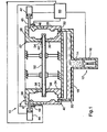
- Fig. 1 illustrates a schematic of one illustrated embodiment of the present invention
- Fig. 2 illustrates the embodiment of Fig. 1 with the molten metal partially filling the molds
- Fig. 3 illustrates the embodiment of Fig. 1 with the molten metal completely filling the molds
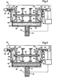
- Fig. 4 illustrates the embodiment of Fig. 1 with the auxiliary pressure being applied to the molten metal in the molds
- Fig. 5 illustrates the embodiment of Fig. 1 with the molten metal partially solidified, in the reservoir
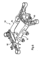
- Fig. 6 illustrates a perspective view of an example of a vehicle cradle that may be produced by an illustrated embodiment of the present invention
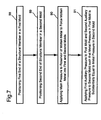
- Fig. 7 illustrates a method in accordance with one aspect of the invention
- Fig. 8 illustrates a method in accordance with another aspect of the invention
- Fig. 9 illustrates a method in accordance with yet another aspect of the invention.
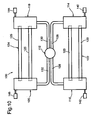
- Fig. 10 illustrates a schematic of another embodiment of the present invention wherein four molds are in operation simultaneously to form two vehicle cradles;
- Figs 11- 17 illustrate various examples of tube end closing and mechanical interlock for use with the present invention.
- Figs. 1-5 illustrate one embodiment of the present invention.
- Fig. 1 illustrates, schematically an assembly 10 for casting metal parts, such as a vehicle cradle 50 as seen in Fig 6 .
- the assembly 10 includes a main or shot tip pressure source 12 illustrated in the form of a shot tip 14 and a hydraulic cylinder 16.
- the shot tip 14 is fluidly coupled to a reservoir or biscuit 18 and contains, along with the reservoir 18 a quantity of molten metal 20.
- the reservoir 18 forms a shot sleeve that is fluidly connected to two die assemblies 22 and 24.
- Die assembly 22 is comprised of at least two die elements 26 and 28, which form a first die cavity or casting area 30.
- Die assembly 22 has a restricted in-gate area 32 that is fluidly coupled to the shot sleeve 18 such that molten metal 20 is capable of being forced through in-gate 32 and into cavity 30.
- die assembly 24 is comprised of at least two die elements 34 and 36, which form a second die cavity or casting area 38.
- Die assembly 24 has a restricted in-gate area 40 that is fluidly coupled to the shot sleeve 18 such that molten metal 20 is capable of being forced through in-gate 40 and into cavity 38.
- the die assemblies 22 and 24 have been illustrated as separate assemblies. It is apparent to those skilled in the art that the die assemblies 22 and 24 can be combined into a single die assembly. The intermediate section between the two die assemblies can be utilized to provide support to the support member 52, as described below.
- Each die assembly 22 and 24 has at least one auxiliary pressure source 42 and 44, respectively, that is attached to a point in the respective cavity 30, 38 that is remote or distal from the in-gates 32, 40.
- auxiliary pressure sources 42 and 44 are spaced as far as possible from the in-gates 32, 40 and most preferably on apposite ends of the cavities 30, 38.
- the auxiliary pressure sources 42 and 44 perform two functions. First, each auxiliary pressure source 42, 44 provides an indication that its respective cavity 30, 38 is sufficiently filled with molten metal 20 and, second, to apply auxiliary pressure to each respective cavity 30, 38 as described below.
- Auxiliary pressure source 42 is illustrated in the figures as an auxiliary hydraulic cylinder having a piston 45 that is connected directly to the die cavity 30. Piston 45 operatively communicates with the cavity 30 and moves in a reciprocating fashion to define an expanded volume and a desired volume.
- Fig. 1 illustrates a limit switch 46 adjacent piston 45 to track its movement in and out of the die cavity 30.
- Auxiliary pressure source 44 is also illustrated in the figures as an auxiliary hydraulic cylinder having a piston 47 that is operatively connected directly to the die cavity 38. Movement of the piston 47, including movement caused by molten metal 20 filling cavity 38, can be monitored in various ways, but is illustrated as a limit switch or position sensor 48 adjacent piston 47 to track its movement in and out of the die cavity 38.
- the composite or hybrid casting assembly is casting the ends of a vehicle cradle 50, which has multiple support members 52, 84 extending between multiple castings 80, 82, as seen in Fig 6 .
- Support member 52 can take various configurations, but is typically a tubular member, such as a high strength steel, hollow tube. Tubes such as tube 52 can be made by operations such as hydroforming, preferably according to known methods as described in United States Patents nos. 5,979,201 ; 6,014,879 ; 6,065,502 ; 6,474,534 ; 6,609,301 ; and 6,662,611 .
- tube 52 is to have a casting on each of two ends 54 and 56 of the tube 52.
- Die assembly 22 has been configured to provide the casting for end 54 and die assembly 24 has been configured to provide the casting for end 56.
- Fig. 1 only shows only tube 52 extending into cavities 30 and 38, multiple tubes such as tube 52 may extend into each of cavities 30 and 38 and become integral with the castings produced by die assemblies 22 and 24, as seen in Fig. 6 .
- Figs. 11 to 17 illustrate various examples of hollow tubes with a closed end.
- the various examples provide two functions: closing the end of the hollow tube and providing a mechanical interlock between the casting to be formed and external surface of the hollow tube.
- the mechanical interlock prevents relative movement, torsional and axial, between the hollow tube and the casting.
- the mechanical interlock is enhanced by providing a mechanical interlock surface.
- Fig. 11 the tube end is crushed between two dies to present a flat end that is wider than the tube. A hole is provided through the flat end to present an interlock surface.
- a separate stamped cap is positioned in the inside of the tube, closing the end.
- the cap is tack welded or crimped to the tube.
- the cap may have a flange having a non-circular configuration to provide a mechanical interlock surface.
- a separate stamped cap is positioned in the outside of the tube, closing the end.
- the cap is tack welded or crimped to the tube.
- the cap may have a flange having a non-circular configuration to provide a mechanical interlock surface.
- a separate stamped cap is positioned on the end of the tube, closing the end.
- the cap is welded to the tube.
- the cap may have a flange or tang having a non-circular configuration to provide a mechanical interlock surface.
- Fig 15 the tube end is subjected to rotary swaging to shape the end in a bayonet shape.
- Fig 16 the material is spun around the ends of the tube, with indents provided on the tube.
- an end cap is welded to the end of the tube and a knurl is applied to the outside surface of the tube to present a mechanical interlock surface.
- Each of the die assemblies 22 and 24 has a tube-receiving opening 55 and 57 and the split or parting line between die elements 26, 28 and 34, 36, respectively.
- Tube-receiving openings 55 and 57 are configured to complementarily receive tube ends 54, 56 respectively in a friction or interference fit.
- the tube-receiving openings 55 and 57 will clamp and retain the tube 52 in place after the die elements 26, 28 and 34, 36, respectively, have been closed.
- tube 52 has been illustrated as being straight and symmetrical, hydroforming enables tube of complex geometries be utilized in the present invention.
- an intermediate die between the die assemblies 22, 24, can be provided to receive the tube 52 and provide support thereto, retaining the tube 52 is position during the casting process.
- controller 60 which may take the form of a computer-based controller assembly or other automated or manually monitored controller assembly.
- Controller 60 can monitor and control the main pressure 12, the auxiliary pressures 42 and 44, and filling of the cavities 30 and 39.
- the filling of the cavities can be monitored by controller 60 monitoring the sensors or limit switches 46 and 48.
- the operation of the embodiment illustrated in Fig. 1 is best illustrated by viewing Fig. 1 in combination with Figs. 2-5 .
- the tube 52 is positioned in the casting assembly 10 such that first end 54 of tube 52 is positioned within first mold 22 and a second end 56 of the tube 52 is positioned within second mold 24.
- the first and second molds 22 and 24 are fluidly coupled to reservoir 18 of molten metal 20.
- a main pressure is applied by hydraulic cylinder 16 and the molten metal 20 in reservoir 18 is forced into the first mold cavity 30 through in-gate 32 and simultaneously into the second mold cavity 38 through in-gate 40.
- the amount of pressure needed from cylinder 16 to fill the cavities 30 and 38 is preferably merely the pressure to overcome the resistance of pushing the molten metal 20 through the restricted in-gates 32 and 40.
- main pressure is applied by cylinder 16 to the molten metal 20 in the reservoir 18 at an initial, mold-filling pressure to force or inject the molten metal 20 into the mold cavities 30 and 38.
- the molten metal 20 encapsulates the ends 54 and 56 of tube 52.
- the molten metal 20 is preferably aluminium. At the moment of injection, the molten metal 20 preferably contains about 40-50% solids at less than 600°C, most preferably 583-595°C.
- the cylinder 16 continues applying the initial filling pressure and the molten metal 20 completely fills each of the mold cavities 30 and 38.
- the pistons 45, 47 for the auxiliary cylinders 42, 44 are free to move with the molten metal 20.
- the molten metal 20 contacts the pistons 45, 47, and urges the pistons 45, 47 outwardly, increasing the volume of the cavities 30, 38 such that the volume of each cavity is increased to an expanded volume. Pistons 45, 47 are pushed and displaced by the molten metal 20.
- the displacement of the piston 45 and 47 may be measured or observed in any variety of ways well known in the art, such as by position sensor or limit switches 46, 48, respectively.
- Limit switches 46 and 48 each generate a respective fill signal once the piston 45, 47 has traveled a predetermined amount.
- the fill signal is transmitted to the controller 60 which responsively activates the auxiliary power sources 42 and 44.
- auxiliary pressure sources 42 and 44 Other devices or mechanisms can be used to determine when the cavities 30 and 38 are filled. Those devices may be integral or separate from the auxiliary pressure sources 42 and 44 or interactively connected such as illustrated. For example, after experimentation with the process to determine how much time it takes to fill each cavity 30 and 38, the timing routine may be established wherein pressures of the main 16 and auxiliary cylinders 42 and 44 are turned on and off based on a predetermined timing sequence. Also, a computer controlled system using controller 60 may be used to automatically monitor the position sensors or limit switches 46, 48 or other monitoring devices or methodologies to determine when the cavities 30 and 38 are filled and when to activate the auxiliary cylinders 42 and 44 and to control the main cylinder 16. Auxiliary cylinders 42 and 44 provide merely one mechanism for determining the fill of the cavities 30 and 38 and other mechanisms can be used that are part of or separate from the auxiliary pressure devices.
- auxiliary cylinders 42 and 44 apply auxiliary pressure to the molten metal 20 in mold cavities 30 and 38, respectively.
- This application of auxiliary pressure by cylinders 42 and 44 moves the pistons 45, 47 from the expanded volume to a desired volume and thereby injects a small amount of molten metal 20 back into the mold cavities 30 and 38 to compensate for or densify the solidifying metal, which shrinks upon cooling.
- the cylinders 42, 44 maintain a predetermined pressure on the molten metal 20 in each of the mold cavities 30 and 38 instead of relying solely on the main cylinder 16.
- auxiliary cylinders 42, 44 the main cylinder 16 would necessarily have to be operated to provide a relatively high pressure once the cavities 30 and 38 were filled with molten metal 20 to provide sufficient pressure on the molten metal 20 in reservoir 18 to continue injection of molten metal 20 into the cavities 30 and 38 during the solidifying stage to ensure that the solidified metal casting conforms to the mold cavity.
- the use of the auxiliary cylinders 42 and 44 permits the main cylinder 16 to apply a relatively lower pressure than in previous casting systems and, as a result, the main cylinder 16 of the subject casting assembly 10 is permitted to be smaller than a main cylinders used in a system without auxiliary pressure supplies 42, 44.
- the main cylinder 16 may continue providing a low pressure to the molten metal 20 during solidification while the necessary pressure on the molten metal 20 for solidifying in cavities 30 and 38 is applied by auxiliary cylinders 42 and 44.
- the main cylinder 16 may be turned off or relaxed once the auxiliary cylinder 42 and 44 begin applying pressure or at sometime thereafter.
- the molten metal 20 begins solidifying.
- the molten metal 20 may initially begin solidifying at places such as at the in-gates 32 and 40 and in the shot sleeve 18. Once the in-gates 32 and 40 solidify, any pressure applied by the main cylinder 16 will cease to be effective in applying the appropriate pressure to any metal still semi-molten in the cavities 30 and 38.
- Fig. 5 illustrates a benefit of the auxiliary cylinders 42 and 44 in that each cylinder continues applying pressure to the molten metal in cavities 30 and 38, respectively, even after the in-gates 32 and 40 are blocked by solidified metal 70.
- the auxiliary cylinders 42 and 44 are turned off and the die elements 26 and 28 and die elements 34 and 36 are opened, respectively, to reveal casts 80 and 82 that are formed from the solidified molten metal 20 in mold cavities 30 and 38, respectively.
- the casts 80 and 82 are rigidly connected to the tubular members 52 and 84 to form, for example, a vehicle cradle 50, such as a cradle front engine cradle or a rear cradle for an automobile, as illustrated.
- one aspect of forming a metal casting is illustrated in the method of forming metal castings, comprising a position step 88 of positioning a first end 54 of a structural member 52 in a first mold cavity 30; a second positioning step 89 of positioning a second end 56 of the structural member 52 in a second mold cavity 38, the first and second mold cavities 30 and 38 being fluidly coupled to a reservoir 18 of molten metal 20; an applying step 90 of applying a main pressure to the molten metal 20 in the reservoir 18 to force the molten metal 20 into the first mold cavity 30 and the second mold cavity 38; and an applying step 91 of applying a first auxiliary pressure to the molten metal in the first mold cavity 30 and a second auxiliary pressure to the molten metal in the second mold cavity 38 such that the metal pressure in the first mold cavity 30 is substantially equal to the metal pressure in the second mold cavity 38.
- a positioning step 88 positioning a first end 54 of a structural member 52 in a first mold cavity 30, the first mold cavity 30 being fluidly coupled to a reservoir 18 of molten metal 20; an applying step 92 applying a main pressure to the molten metal 20 in the reservoir 18 at an initial, mold-filling pressure to force the molten metal 20 into the first mold cavity 30; another application step 93 of applying a first auxiliary pressure to the molten metal in the first mold cavity 30; and a maintaining step 94 of maintaining the main pressure at or less than the initial, mold-filling pressure after the first mold cavity 30 has been filled.
- FIG. 9 another aspect of forming a metal casting is illustrated in the method of forming composite metal castings, comprising: the positioning step 88 of positioning a first end 55 of a structural member 52 in a first mold cavity 30, the first mold cavity 30 being fluidly coupled to a reservoir 18 of molten metal 20; an application step 95 of applying a main pressure to the molten metal 20 in the reservoir 18 to force the molten metal 20 into the first mold cavity 30; a detecting step 96 of detecting whether the first mold cavity 30 is sufficiently filled with molten metal 20 by monitoring a moveable element 45; and an application step 97 of applying a first auxiliary pressure to the molten metal in the first mold cavity after detecting that the first mold cavity 30 is sufficiently filled.
- the size of a semi-solid sub-liquidus casting (SLC) machine is defined by the platen size and the clamp tonnage.
- the platen size determines the largest die dimension that can physically fit under the clamp of the press.
- the clamp tonnage is defined by the product of the "projected area" times the metal pressure.
- Metal pressure relative to the size of casting defects and associated material properties is significant up to a metal pressure of 4 tons per square inch. Further increases in metal pressure in excess of 4 tons per square inch are reported to provide little additional value.
- the sub-liquidus casting (SLC) process semi-solid casting process includes the biscuit or molten metal reservoir 18 (typically 20" diameter) from which molten metal 20 is transferred into the die cavities 30 and 38 via a hydraulic cylinder 16 and shot tip assembly 14.
- the machine tonnage required is determined by the product of the metal pressure (i.e., approximately 4 tons per square inch) times the sum of the projected area of the shot tip (biscuit) assembly 14 and 18 and the projected area of the castings outside the perimeter if the shot tip biscuit assembly 14, 18.
- the SLC process would ordinarily assume that the majority of the casting projected area is located directly above the shot tip/biscuit area.
- the platen size is thus designed to accommodate a relatively large die, presenting metal pressure and casting projected area (shot tip plus casting area) as the limiting features which define the machine tonnage requirements.
- the "controlled pressure" method of the subject application is particularly applicable to the manufacture of "hybrid material” cast automotive components such as cradles which are typically separated by high strength steel tubes. Separation of the castings results in a significant amount of the casting area to be outside of the projected area of the biscuit 18, thus increasing the machine size tonnage requirement of, for example, main cylinder 18.
- the controlled pressure method utilizes the shot tip assembly 14, 18 to inject metal into the dies 30 and 38 and auxiliary cylinders 42 and 44 provide pressure after the die cavities 30 and 38 are full. This technique results in limiting the metal pressure during the die fill and initial solidification phase to that of the machine clamp tonnage divided by the total projected area associated with the biscuit 14, 18 and casting area 30, 38. Once the cavities 30, 38 are full, the shot tip pressure is reduced and auxiliary cylinders 42 and 44 integral to the die cavities 30 and 38, respectively, are actuated, providing pressure to only the casting projected area.
- Shot tip/biscuit diameter 20 in Shot tip/biscuit projected area: 314 in 2 Casting projected area (outside perimeter of shot tip) 192 in 2 Total projected area (casting & shot tip): 506 in 2 (192 + 314) Required machine tonnage @ 8,000 psi (4 tons/in 2 ) metal pressure 2,000 ton
- Shot tip/biscuit diameter 20 in Shot tip/biscuit projected area: 314 in 2 Casting projected area (outside perimeter of shot tip) 192 in 2 Metal pressure permitted at end of die fill 2 ton/in 2 Required machine tonnage @ 8,000 psi (4 tons/in 2 ) metal pressure 768 ton
- the required machine tonnage is less than the required machine tonnage using conventional methods and apparatus.
- the embodiments of the subject application which are referred to as "controlled pressure" casting, provides the capability to cast components such as a rear cradle or front engine cradle in one casting machine cycle, in a reduced machine tonnage that is relative to only the "saleable" casting projected area (the casts 80, 82 themselves) rather the sum of the projected area of the castings 80 and 82 and biscuit 18.
- Fig. 10 illustrates a casting assembly 110 in accordance with another embodiment of the invention wherein one shot tip pressure assembly 112 supplies molten metal to four casting die assemblies 114, 116, 118, 120 so that two vehicle cradles 122 and 124 may be cast simultaneously.
- Each vehicle cradle 122 and 124 is shown with two structural members 123 and 125, respectively, and each engine cradle 122 and 124 can be similar to cradle 50 in Fig. 6 .
- the structural members 123 and 125 may be substantially identical to tube 52 in composition and make-up.
- the specific shape of any structural members 123 and 125 will vary dependent upon the specific vehicle cradle formed. As mentioned above, such an arrangement as illustrated in Fig. 10 is possible due to the efficiencies of the casting assemblies disclosed herein in the embodiments of the subject application.
- main pressure assembly 112 is fluidly coupled to the die cavity of each die assembly 114, 116, 118, 120 by shot sleeves 126, 128, 130 and 132, respectively.
- Each die assembly 114, 116, 118, 120 receives the ends of two structural members 123, 125 so that the castings formed in each die assembly 114, 11, 118, 1220 will encapsulate two ends of the structural members 123 and 125.
- Each die assembly 114, 116, 118, 120 also has an auxiliary pressure source 140, 142, 144, and 146, which is similar to auxiliary pressure sources 42 and 44 described above.
- the casting assembly 110 can be controlled by controller 60 in a manner as described above with respect to controller 60.
- the configuration of the casting assembly 110 is substantially identical to casting assembly 10 described above.
- FIG. 10 illustrates one of the efficiencies of the illustrated embodiments of the subject application. That is, since auxiliary pressures are applied to each die 114, 116, 118, 120 during solidifying, the main pressure supplied to each die 114, 116, 118, 20 by main cylinder 116 is less than the pressures typically applied by main cylinders in prior art casting arrangements. Thus, since the main pressure in the embodiments of the subject application are lower, the size requirements of the pressure system and for the main hydraulic cylinder is less. This permits the embodiments of the subject application to utilize smaller main hydraulic cylinders and smaller pressure requirements. Alternatively, with the same size and pressure constraints found in the prior art, embodiments of the subject application can be used to fill a greater number of die cavities with molten metal 20.
- a prior art configuration may only be used to cast one vehicle cradle member
- embodiments of the subject application may be used to produce more castings, for example, two cradle assemblies that each require two castings.
- the embodiment of Fig. 10 may produce, for example, four casting per cycle using the same pressure and sized machinery.
- embodiments of the subject application utilize a minimum level of hydraulic pressure required to transfer molten metal 20 from the shot sleeve 18 through the in-gates 32 and 40 to the die cavities 30 and 38.
- the hydraulic pressure from the main pressure cylinder 16 that is needed to fill the cavities 30 and 38 is much less than the hydraulic pressure needed from a main pressure cylinder of, for example, a prior art device that only relies upon one pressure source - the main pressure source - to provide pressure during solidifying to reduce the volume of entrapped air and increase the rate of heat transfer during solidifying.
- the embodiments of the subject application also incorporate moveable cores (squeeze pins) in the form of auxiliary hydraulic cylinders 42 and 44 in each die cavity 30 and 38, respectively.
- the auxiliary cylinders 42 and 44 are capable of detecting that their respective die cavity 30 and 38 is full, prior to increasing the metal pressure within the cavities 30 and 38.
- Embodiments of the subject application also simultaneously actuate the auxiliary hydraulic cylinders 42 and 44 acting as moveable cores to increase metal pressure integral to each die cavity 30 and 38, respectively, which share a common submerged member 52.
- embodiments of the subject application illustrate a method of densifying the metal in multiple cavity dies 30, 38 to minimize the main pressure force.
- embodiments of the subject application also provide a method of detecting whether die cavities such as cavities 30 and 38 are filled with molten metal 20 by using a moveable core, such as in the form of auxiliary hydraulic cylinders 42 and 44.
Landscapes
- Engineering & Computer Science (AREA)
- Mechanical Engineering (AREA)
- Chemical & Material Sciences (AREA)
- Combustion & Propulsion (AREA)
- Transportation (AREA)
- Architecture (AREA)
- Structural Engineering (AREA)
- Molds, Cores, And Manufacturing Methods Thereof (AREA)
- Body Structure For Vehicles (AREA)
Abstract
Description
- The present invention relates to casting metal structures. More specifically, the present application illustrates embodiments of the present invention, including those relating to the improvement of casting metal structures using controlled, auxiliary pressure and to improvements in filling casting molds.
- Conventional aluminium high pressure die casting utilizes a hydraulic cylinder to advance a shot tip, displacing molten aluminium from the shot sleeve into the die cavity, overcoming the resistance to flow through the restricted gate area. When the die cavity is filled with molten aluminium, the pressure applied to the hydraulic shot cylinder is transferred to the molten aluminium based upon the ratio of the shot cylinder and shot tip cross-sectional area. If the die cavity containing one end of a submerged member fills and becomes pressurized before the die cavity or region of the die containing the opposing end of the submerged member, a resultant force is imposed on the end of the submerged member. To avoid movement of the submerged member, a mechanism must be employed, such as a clamp or a friction or form fitting die, to resist the force. As the cross-sectional area of the member increases, the forces become very high and difficult to manage with such mechanisms. Subsequent to filling of the die cavity, the pressure applied to the hydraulic cylinder advancing the shot tip is typically increased (i.e., intensified) by, for example, a factor of two times to reduce the volume of entrapped air and increase the rate of heat transfer. Also, once the in-gates have frozen-off through solidifying, which usually occurs prior to the solidifying of the entire die cavity, even the increased pressure fails to reach the material within the cavities being molded.
-
U.S. Patent No. 3,664,410 to Groteke andU.S. Patent No. 4, 779,666 to Ruhlandt et al. , disclose each a die casting process and apparatus. - One aspect of the invention relates to a method of forming composite metal castings. A first end of a structural member is positioned in a first mold cavity and a second end of the structural member is positioned in a second mold cavity. The first and second mold cavities are fluidly coupled to a reservoir of molten metal. A main pressure is applied to the molten metal in the reservoir to force the molten metal into the first mold cavity and the second mold cavity. A first auxiliary pressure is applied to the molten metal in the first mold cavity and a second auxiliary pressure is applied to the molten metal in the second mold cavity to densify the casting formed in the first mold cavity and in the second mold cavity.
- Another aspect of the invention relates to a method of forming metal castings, comprising: positioning a first end of a structural member in a first mold cavity, the first mold being fluidly coupled to a reservoir of molten metal; applying a main pressure to the molten metal in the reservoir at an initial, mold-filling pressure to force the molten metal into the first mold cavity; applying a first auxiliary pressure to the molten metal in the first mold cavity; and maintaining the main pressure at or less than the initial, mold-filling pressure after the first mold cavity has been filled.
- Another aspect of the invention is a method of forming metal castings, comprising: positioning a first end of a structural member in a first mold cavity, the first mold cavity being fluidly coupled to a reservoir of molten metal; applying a main pressure to the molten metal in the reservoir to force the molten metal into the first mold cavity; detecting whether the first mold cavity is sufficiently filled with molten metal by monitoring a moveable element; and applying a first auxiliary pressure to the first mold cavity after detecting that the first mold cavity is sufficiently filled.
- Other aspects, features, and advantages of this invention will become apparent from the following detailed description when taken in conjunction with the accompanying drawings, which are a part of this disclosure and which illustrate, by way of example, the principles of this invention.
- The accompanying drawings facilitate an understanding of the various embodiments of this invention. In such drawings:
-
Fig. 1 illustrates a schematic of one illustrated embodiment of the present invention; -
Fig. 2 illustrates the embodiment ofFig. 1 with the molten metal partially filling the molds; -
Fig. 3 illustrates the embodiment ofFig. 1 with the molten metal completely filling the molds; -
Fig. 4 illustrates the embodiment ofFig. 1 with the auxiliary pressure being applied to the molten metal in the molds; -
Fig. 5 illustrates the embodiment ofFig. 1 with the molten metal partially solidified, in the reservoir; -
Fig. 6 illustrates a perspective view of an example of a vehicle cradle that may be produced by an illustrated embodiment of the present invention; -
Fig. 7 illustrates a method in accordance with one aspect of the invention; -
Fig. 8 illustrates a method in accordance with another aspect of the invention; -
Fig. 9 illustrates a method in accordance with yet another aspect of the invention; -
Fig. 10 illustrates a schematic of another embodiment of the present invention wherein four molds are in operation simultaneously to form two vehicle cradles; and -
Figs 11- 17 illustrate various examples of tube end closing and mechanical interlock for use with the present invention. -
Figs. 1-5 illustrate one embodiment of the present invention.Fig. 1 illustrates, schematically anassembly 10 for casting metal parts, such as avehicle cradle 50 as seen inFig 6 . Theassembly 10 includes a main or shottip pressure source 12 illustrated in the form of ashot tip 14 and ahydraulic cylinder 16. Theshot tip 14 is fluidly coupled to a reservoir orbiscuit 18 and contains, along with the reservoir 18 a quantity ofmolten metal 20. Thereservoir 18 forms a shot sleeve that is fluidly connected to twodie assemblies assembly 22 is comprised of at least two dieelements casting area 30. Dieassembly 22 has a restricted in-gatearea 32 that is fluidly coupled to theshot sleeve 18 such thatmolten metal 20 is capable of being forced through in-gate 32 and intocavity 30. Similarly, dieassembly 24 is comprised of at least two dieelements casting area 38. Dieassembly 24 has a restricted in-gatearea 40 that is fluidly coupled to theshot sleeve 18 such thatmolten metal 20 is capable of being forced through in-gate 40 and intocavity 38. - In the Figures, the die
assemblies assemblies support member 52, as described below. - Each die
assembly auxiliary pressure source respective cavity gates auxiliary pressure sources gates cavities auxiliary pressure sources auxiliary pressure source respective cavity molten metal 20 and, second, to apply auxiliary pressure to eachrespective cavity Auxiliary pressure source 42 is illustrated in the figures as an auxiliary hydraulic cylinder having apiston 45 that is connected directly to thedie cavity 30. Piston 45 operatively communicates with thecavity 30 and moves in a reciprocating fashion to define an expanded volume and a desired volume. - Movement of the
piston 45, including movement caused bymolten metal 20filling cavity 30, can be monitored in various ways.Fig. 1 illustrates alimit switch 46adjacent piston 45 to track its movement in and out of thedie cavity 30.Auxiliary pressure source 44 is also illustrated in the figures as an auxiliary hydraulic cylinder having apiston 47 that is operatively connected directly to thedie cavity 38. Movement of thepiston 47, including movement caused bymolten metal 20filling cavity 38, can be monitored in various ways, but is illustrated as a limit switch orposition sensor 48adjacent piston 47 to track its movement in and out of thedie cavity 38. - In the illustrated embodiment of
Fig. 1 , the composite or hybrid casting assembly is casting the ends of avehicle cradle 50, which hasmultiple support members multiple castings Fig 6 . InFig. 1 , only onesupport member 52 is illustrated but it should be understood that the other support members can be made in a substantially identical manner or in different configurations, as desired, such as seen inFig 6 .Support member 52 can take various configurations, but is typically a tubular member, such as a high strength steel, hollow tube. Tubes such astube 52 can be made by operations such as hydroforming, preferably according to known methods as described in United States Patents nos.5,979,201 ;6,014,879 ;6,065,502 ;6,474,534 ;6,609,301 ; and6,662,611 . - To form
cradle 50,tube 52 is to have a casting on each of twoends tube 52. Dieassembly 22 has been configured to provide the casting forend 54 and dieassembly 24 has been configured to provide the casting forend 56. AlthoughFig. 1 only shows onlytube 52 extending intocavities tube 52 may extend into each ofcavities assemblies Fig. 6 . - The ends 54 and 56 of
tube 52 extend into eachcavity end molten metal 20 does not enter thehollow tube 52.Figs. 11 to 17 illustrate various examples of hollow tubes with a closed end. The various examples provide two functions: closing the end of the hollow tube and providing a mechanical interlock between the casting to be formed and external surface of the hollow tube. The mechanical interlock prevents relative movement, torsional and axial, between the hollow tube and the casting. The mechanical interlock is enhanced by providing a mechanical interlock surface. - In
Fig. 11 , the tube end is crushed between two dies to present a flat end that is wider than the tube. A hole is provided through the flat end to present an interlock surface. - In
Fig. 12 , a separate stamped cap is positioned in the inside of the tube, closing the end. The cap is tack welded or crimped to the tube. The cap may have a flange having a non-circular configuration to provide a mechanical interlock surface. - In
Fig. 13 , a separate stamped cap is positioned in the outside of the tube, closing the end. The cap is tack welded or crimped to the tube. The cap may have a flange having a non-circular configuration to provide a mechanical interlock surface. - In
Fig 14 , a separate stamped cap is positioned on the end of the tube, closing the end. The cap is welded to the tube. The cap may have a flange or tang having a non-circular configuration to provide a mechanical interlock surface. - In
Fig 15 , the tube end is subjected to rotary swaging to shape the end in a bayonet shape. - In
Fig 16 , the material is spun around the ends of the tube, with indents provided on the tube. - In
Fig. 17 , an end cap is welded to the end of the tube and a knurl is applied to the outside surface of the tube to present a mechanical interlock surface. - Each of the
die assemblies opening 55 and 57 and the split or parting line betweendie elements openings 55 and 57 are configured to complementarily receive tube ends 54, 56 respectively in a friction or interference fit. The tube-receivingopenings 55 and 57 will clamp and retain thetube 52 in place after thedie elements tube 52 has been illustrated as being straight and symmetrical, hydroforming enables tube of complex geometries be utilized in the present invention. To enhance the clamping capabilities, an intermediate die between thedie assemblies tube 52 and provide support thereto, retaining thetube 52 is position during the casting process. - Preferably, the
assembly 10, as illustrated inFig. 1 , is controlled bycontroller 60, which may take the form of a computer-based controller assembly or other automated or manually monitored controller assembly.Controller 60 can monitor and control themain pressure 12, theauxiliary pressures cavities 30 and 39. In the illustrated embodiment, the filling of the cavities can be monitored bycontroller 60 monitoring the sensors orlimit switches - The operation of the embodiment illustrated in
Fig. 1 is best illustrated by viewingFig. 1 in combination withFigs. 2-5 . Thetube 52 is positioned in the castingassembly 10 such thatfirst end 54 oftube 52 is positioned withinfirst mold 22 and asecond end 56 of thetube 52 is positioned withinsecond mold 24. - The first and
second molds reservoir 18 ofmolten metal 20. A main pressure is applied byhydraulic cylinder 16 and themolten metal 20 inreservoir 18 is forced into thefirst mold cavity 30 throughin-gate 32 and simultaneously into thesecond mold cavity 38 throughin-gate 40. The amount of pressure needed fromcylinder 16 to fill thecavities molten metal 20 through the restricted in-gates cylinder 16 to themolten metal 20 in thereservoir 18 at an initial, mold-filling pressure to force or inject themolten metal 20 into themold cavities Fig. 2 , as themolten metal 20 begins filling thecavities molten metal 20 encapsulates theends tube 52. - The
molten metal 20 is preferably aluminium. At the moment of injection, themolten metal 20 preferably contains about 40-50% solids at less than 600°C, most preferably 583-595°C. - As seen in
Fig. 3 , thecylinder 16 continues applying the initial filling pressure and themolten metal 20 completely fills each of themold cavities pistons auxiliary cylinders molten metal 20. Themolten metal 20 contacts thepistons pistons cavities Pistons molten metal 20. - The displacement of the
piston limit switches piston controller 60 which responsively activates theauxiliary power sources - Other devices or mechanisms can be used to determine when the
cavities auxiliary pressure sources cavity auxiliary cylinders system using controller 60 may be used to automatically monitor the position sensors orlimit switches cavities auxiliary cylinders main cylinder 16.Auxiliary cylinders cavities - As seen in
Fig. 4 , with themain cylinder 16 still applying an initial, fill pressure, or with themain cylinder 16 being turned off or relaxed, theauxiliary cylinders molten metal 20 inmold cavities cylinders pistons molten metal 20 back into themold cavities cylinders molten metal 20 in each of themold cavities main cylinder 16. Without the use ofauxiliary cylinders main cylinder 16 would necessarily have to be operated to provide a relatively high pressure once thecavities molten metal 20 to provide sufficient pressure on themolten metal 20 inreservoir 18 to continue injection ofmolten metal 20 into thecavities auxiliary cylinders main cylinder 16 to apply a relatively lower pressure than in previous casting systems and, as a result, themain cylinder 16 of thesubject casting assembly 10 is permitted to be smaller than a main cylinders used in a system without auxiliary pressure supplies 42, 44. - Depending on the casting process being carried out, the
main cylinder 16 may continue providing a low pressure to themolten metal 20 during solidification while the necessary pressure on themolten metal 20 for solidifying incavities auxiliary cylinders main cylinder 16 may be turned off or relaxed once theauxiliary cylinder - Eventually, as seen in
Fig. 5 , themolten metal 20 begins solidifying. Themolten metal 20 may initially begin solidifying at places such as at the in-gates shot sleeve 18. Once the in-gates main cylinder 16 will cease to be effective in applying the appropriate pressure to any metal still semi-molten in thecavities Fig. 5 illustrates a benefit of theauxiliary cylinders cavities gates metal 70. - Once the
molten metal 20 is completely and sufficiently solidified, theauxiliary cylinders die elements elements casts molten metal 20 inmold cavities Fig. 6 , thecasts tubular members vehicle cradle 50, such as a cradle front engine cradle or a rear cradle for an automobile, as illustrated. - As seen in
Fig. 7 , one aspect of forming a metal casting is illustrated in the method of forming metal castings, comprising aposition step 88 of positioning afirst end 54 of astructural member 52 in afirst mold cavity 30; asecond positioning step 89 of positioning asecond end 56 of thestructural member 52 in asecond mold cavity 38, the first andsecond mold cavities reservoir 18 ofmolten metal 20; an applyingstep 90 of applying a main pressure to themolten metal 20 in thereservoir 18 to force themolten metal 20 into thefirst mold cavity 30 and thesecond mold cavity 38; and an applyingstep 91 of applying a first auxiliary pressure to the molten metal in thefirst mold cavity 30 and a second auxiliary pressure to the molten metal in thesecond mold cavity 38 such that the metal pressure in thefirst mold cavity 30 is substantially equal to the metal pressure in thesecond mold cavity 38. - As seen in
Fig. 8 , another aspect of forming a composite metal casting is illustrated in the method of forming metal castings, comprising: a positioningstep 88 positioning afirst end 54 of astructural member 52 in afirst mold cavity 30, thefirst mold cavity 30 being fluidly coupled to areservoir 18 ofmolten metal 20; an applyingstep 92 applying a main pressure to themolten metal 20 in thereservoir 18 at an initial, mold-filling pressure to force themolten metal 20 into thefirst mold cavity 30; anotherapplication step 93 of applying a first auxiliary pressure to the molten metal in thefirst mold cavity 30; and a maintainingstep 94 of maintaining the main pressure at or less than the initial, mold-filling pressure after thefirst mold cavity 30 has been filled. - As seen in
Fig. 9 , another aspect of forming a metal casting is illustrated in the method of forming composite metal castings, comprising: the positioningstep 88 of positioning a first end 55 of astructural member 52 in afirst mold cavity 30, thefirst mold cavity 30 being fluidly coupled to areservoir 18 ofmolten metal 20; anapplication step 95 of applying a main pressure to themolten metal 20 in thereservoir 18 to force themolten metal 20 into thefirst mold cavity 30; a detectingstep 96 of detecting whether thefirst mold cavity 30 is sufficiently filled withmolten metal 20 by monitoring amoveable element 45; and anapplication step 97 of applying a first auxiliary pressure to the molten metal in the first mold cavity after detecting that thefirst mold cavity 30 is sufficiently filled. - The size of a semi-solid sub-liquidus casting (SLC) machine is defined by the platen size and the clamp tonnage. The platen size determines the largest die dimension that can physically fit under the clamp of the press. The clamp tonnage is defined by the product of the "projected area" times the metal pressure. Metal pressure relative to the size of casting defects and associated material properties is significant up to a metal pressure of 4 tons per square inch. Further increases in metal pressure in excess of 4 tons per square inch are reported to provide little additional value.
- In one embodiment of the system of
Figs. 1-5 , the sub-liquidus casting (SLC) process semi-solid casting process includes the biscuit or molten metal reservoir 18 (typically 20" diameter) from whichmolten metal 20 is transferred into thedie cavities hydraulic cylinder 16 and shottip assembly 14. The machine tonnage required is determined by the product of the metal pressure (i.e., approximately 4 tons per square inch) times the sum of the projected area of the shot tip (biscuit)assembly tip biscuit assembly - The SLC process would ordinarily assume that the majority of the casting projected area is located directly above the shot tip/biscuit area. The platen size is thus designed to accommodate a relatively large die, presenting metal pressure and casting projected area (shot tip plus casting area) as the limiting features which define the machine tonnage requirements.
- The "controlled pressure" method of the subject application is particularly applicable to the manufacture of "hybrid material" cast automotive components such as cradles which are typically separated by high strength steel tubes. Separation of the castings results in a significant amount of the casting area to be outside of the projected area of the
biscuit 18, thus increasing the machine size tonnage requirement of, for example,main cylinder 18. The controlled pressure method utilizes theshot tip assembly auxiliary cylinders die cavities biscuit area cavities auxiliary cylinders die cavities - Specifically, this can be seen when taking a specific rear cradle example:
-
Shot tip/biscuit diameter: 20 in Shot tip/biscuit projected area: 314 in2 Casting projected area (outside perimeter of shot tip) 192 in2 Total projected area (casting & shot tip): 506 in2 (192 + 314) Required machine tonnage @ 8,000 psi (4 tons/in2) metal pressure 2,000 ton -
Shot tip/biscuit diameter: 20 in Shot tip/biscuit projected area: 314 in2 Casting projected area (outside perimeter of shot tip) 192 in2 Metal pressure permitted at end of die fill 2 ton/in2 Required machine tonnage @ 8,000 psi (4 tons/in2) metal pressure 768 ton - Thus, when using the method in accordance with the embodiments of the subject application, the required machine tonnage is less than the required machine tonnage using conventional methods and apparatus. The embodiments of the subject application, which are referred to as "controlled pressure" casting, provides the capability to cast components such as a rear cradle or front engine cradle in one casting machine cycle, in a reduced machine tonnage that is relative to only the "saleable" casting projected area (the
casts castings biscuit 18. -
Fig. 10 illustrates a casting assembly 110 in accordance with another embodiment of the invention wherein one shottip pressure assembly 112 supplies molten metal to four casting dieassemblies vehicle cradle structural members engine cradle cradle 50 inFig. 6 . Thestructural members tube 52 in composition and make-up. Of course, the specific shape of anystructural members Fig. 10 is possible due to the efficiencies of the casting assemblies disclosed herein in the embodiments of the subject application. - In
Fig. 10 ,main pressure assembly 112 is fluidly coupled to the die cavity of each dieassembly sleeves die assembly structural members assembly structural members die assembly auxiliary pressure source auxiliary pressure sources controller 60 in a manner as described above with respect tocontroller 60. Other than themain pressure 112 supplying molten metal to four dieassemblies assembly 10 described above. - The embodiment of
Fig. 10 illustrates one of the efficiencies of the illustrated embodiments of the subject application. That is, since auxiliary pressures are applied to each die 114, 116, 118, 120 during solidifying, the main pressure supplied to each die 114, 116, 118, 20 bymain cylinder 116 is less than the pressures typically applied by main cylinders in prior art casting arrangements. Thus, since the main pressure in the embodiments of the subject application are lower, the size requirements of the pressure system and for the main hydraulic cylinder is less. This permits the embodiments of the subject application to utilize smaller main hydraulic cylinders and smaller pressure requirements. Alternatively, with the same size and pressure constraints found in the prior art, embodiments of the subject application can be used to fill a greater number of die cavities withmolten metal 20. For example, wherein the a prior art configuration may only be used to cast one vehicle cradle member, embodiments of the subject application may be used to produce more castings, for example, two cradle assemblies that each require two castings. Thus, whereas the prior art could make, for example, two castings per cycle, the embodiment ofFig. 10 may produce, for example, four casting per cycle using the same pressure and sized machinery. - Thus, embodiments of the subject application utilize a minimum level of hydraulic pressure required to transfer
molten metal 20 from theshot sleeve 18 through the in-gates die cavities main pressure cylinder 16 that is needed to fill thecavities hydraulic cylinders cavity auxiliary cylinders respective die cavity cavities - Embodiments of the subject application also simultaneously actuate the auxiliary
hydraulic cylinders cavity member 52. Thus, embodiments of the subject application illustrate a method of densifying the metal in multiple cavity dies 30, 38 to minimize the main pressure force. - Also, embodiments of the subject application also provide a method of detecting whether die cavities such as
cavities molten metal 20 by using a moveable core, such as in the form of auxiliaryhydraulic cylinders - The foregoing specific embodiments have been provided to illustrate the structural and functional principles of the present invention, and are not intended to be limiting. To the contrary, the present invention is intended to encompass all modifications, alterations, and substitutions within the scope of the appended claims.
Claims (14)
- A composite casting comprising:a steel member;an end cap fastened to an end portion of the steel member; anda cast coupling member cast about the end portion of the steel member including the end cap, thereby positively and rigidly locking and securing said cast coupling member to said steel member.
- The composite casting as defined in claim 1, wherein the steel member is a tubular member.
- The composite casting as defined in claim 1 or 2 wherein the steel member is made from high strength steel.
- The composite casting as defined in any one of claims 1 to 3 wherein the end cap has a flange or a tang having one of a circular and a non-circular configuration for providing a mechanical interlock surface.
- The composite casting as defined in any one of claims 1 to 4 further comprising a knurl or an indent on an outside surface about the end portion of the steel member for providing a mechanical interlock surface.
- The composite casting as defined in any one of claims 1 to 5 wherein the cast coupling member is made from aluminium.
- The composite casting as defined in any one of claims 1 to 6 wherein the end cap is fastened on the inside or on the outside of the end portion of the steel member
- An engine cradle for a motor vehicle, comprising:a frame assembly having a pair of spaced rails secured by spaced cross members;at least one of said spaced rails and said spaced cross members including a composite casting, including:a steel member;an end cap fastened to an end portion of the steel member; anda cast coupling member cast about the end portion of the steel member including the end cap, thereby positively and rigidly securing the cast coupling member to the steel member.
- The engine cradle as defined in claim 8 wherein the cast coupling member is casted about the end portion of the steel member by casting-in-place aluminium about said end cap and said end portion.
- The engine cradle as defined in claim 8 or 9 wherein the steel member is a tubular member.
- A composite casting comprising:a steel member;an end cap fastened to an open portion of the steel member; anda cast coupling member cast about the end cap of said steel member by casting-in-place aluminum about said end cap, thereby positively and rigidly securing said coupling member to said steel member.
- The composite casting as defined in claim 11 wherein the steel member is a tubular member.
- The composite casting as defined in claim 11 or 12 wherein said end cap about which said cast coupling member is casted is a mid portion of said tubular member.
- The composite casting as defined in claim 13, wherein said mid portion includes a section having a non-circular cross-section.
Applications Claiming Priority (3)
| Application Number | Priority Date | Filing Date | Title |
|---|---|---|---|
| US68232905P | 2005-05-19 | 2005-05-19 | |
| EP06741532A EP1881876B1 (en) | 2005-05-19 | 2006-05-19 | Controlled pressure casting |
| PCT/CA2006/000820 WO2006122423A1 (en) | 2005-05-19 | 2006-05-19 | Controlled pressure casting |
Related Parent Applications (2)
| Application Number | Title | Priority Date | Filing Date |
|---|---|---|---|
| EP06741532A Division EP1881876B1 (en) | 2005-05-19 | 2006-05-19 | Controlled pressure casting |
| EP06741532.3 Division | 2006-05-19 |
Publications (3)
| Publication Number | Publication Date |
|---|---|
| EP2388181A2 true EP2388181A2 (en) | 2011-11-23 |
| EP2388181A3 EP2388181A3 (en) | 2012-07-18 |
| EP2388181B1 EP2388181B1 (en) | 2020-06-17 |
Family
ID=37430905
Family Applications (2)
| Application Number | Title | Priority Date | Filing Date |
|---|---|---|---|
| EP11006756.8A Ceased EP2388181B1 (en) | 2005-05-19 | 2006-05-19 | Composite casting |
| EP06741532A Ceased EP1881876B1 (en) | 2005-05-19 | 2006-05-19 | Controlled pressure casting |
Family Applications After (1)
| Application Number | Title | Priority Date | Filing Date |
|---|---|---|---|
| EP06741532A Ceased EP1881876B1 (en) | 2005-05-19 | 2006-05-19 | Controlled pressure casting |
Country Status (6)
| Country | Link |
|---|---|
| US (1) | US7806162B2 (en) |
| EP (2) | EP2388181B1 (en) |
| KR (2) | KR101324407B1 (en) |
| CN (2) | CN102527997B (en) |
| CA (2) | CA2608168C (en) |
| WO (1) | WO2006122423A1 (en) |
Families Citing this family (19)
| Publication number | Priority date | Publication date | Assignee | Title |
|---|---|---|---|---|
| US8899624B2 (en) * | 2005-05-19 | 2014-12-02 | Magna International Inc. | Controlled pressure casting |
| US8496258B2 (en) * | 2003-10-20 | 2013-07-30 | Magna International Inc. | Hybrid component |
| CA2620867C (en) | 2005-07-18 | 2014-09-30 | Magna International Inc. | Control arm and knuckle assembly |
| ITTO20070934A1 (en) * | 2007-12-21 | 2009-06-22 | Solmar S A S Di Luisa Maria Ma | EQUIPMENT FOR THE MANUFACTURE OF METAL ARTICLES, IN PARTICULAR OF LIGHT ALLOY. |
| MX2012008451A (en) * | 2010-01-20 | 2012-08-15 | Magna Int Inc | Bi-metallic component and method of making the same. |
| CA2801611A1 (en) * | 2010-06-10 | 2011-12-15 | Magna International Inc. | Bi-metallic component and method |
| DE102010038260A1 (en) * | 2010-10-19 | 2012-04-19 | Ford Global Technologies, Llc. | Method for producing a composite beam axle in mixed construction |
| DE102010053346B4 (en) * | 2010-12-03 | 2013-04-25 | Daimler Ag | Diagonal strut device, method for their production and reinforced by diagonal strut device motor vehicle underbody |
| DE102011108126A1 (en) | 2011-07-21 | 2013-01-24 | Universität Siegen | Manufacturing cast component, preferably a cast knot, comprises inserting at least one metallic inlay profile, preferably inlay-sheet profile into a casting mold, and at least positively recasting with a cast metal in partial areas |
| KR101416662B1 (en) | 2012-02-06 | 2014-07-14 | 주식회사 한국몰드 | FRP mold structure |
| DE102012108051B4 (en) * | 2012-08-30 | 2014-10-09 | Benteler Automobiltechnik Gmbh | Method for producing a steel component with casting bodies |
| DE102013105433B3 (en) * | 2013-05-27 | 2014-05-22 | Schuler Pressen Gmbh | Casting device with a loop and casting process |
| TWM483166U (en) * | 2014-03-11 | 2014-08-01 | Shao-Yang Hung | Two-stage hydraulic pressurization device for in-mold functional components |
| CN104368783B (en) * | 2014-10-17 | 2016-09-28 | 烟台三和新能源科技股份有限公司 | pressure casting system and method |
| JP6421679B2 (en) * | 2015-04-02 | 2018-11-14 | 株式会社デンソー | Manufacturing method of casting products |
| CN112108632A (en) * | 2019-06-19 | 2020-12-22 | 上海一达机械有限公司 | Die casting control method and semi-solid die casting machine |
| CN116786795A (en) * | 2023-03-17 | 2023-09-22 | 联想(北京)有限公司 | Processing method, shell and electronic equipment |
| WO2025033549A1 (en) * | 2023-08-09 | 2025-02-13 | 株式会社リンリン | Steel insert-cast vehicle body structure and die casting device |
| CN119457000A (en) * | 2025-01-09 | 2025-02-18 | 浙江继望锻造科技有限公司 | A forging device and forging method for large bucket teeth |
Family Cites Families (10)
| Publication number | Priority date | Publication date | Assignee | Title |
|---|---|---|---|---|
| US3664410A (en) * | 1969-06-12 | 1972-05-23 | American Standard Inc | Die casting densifier and ejector apparatus |
| US4779666A (en) * | 1982-06-23 | 1988-10-25 | General Motors Corporation | Die casting process and apparatus comprising in-die plunger densification |
| JPH01157753A (en) * | 1987-02-16 | 1989-06-21 | Teisan Ind:Kk | Die-casting device |
| IT1222827B (en) * | 1987-10-05 | 1990-09-12 | Tva Holding | CASTING METAL PROCESS, IN PARTICULAR OF ALUMINUM ALLOYS AND MAGNESIUM ALLOYS AND DEVICE FOR ITS EXECUTION |
| JPH06210426A (en) * | 1992-03-04 | 1994-08-02 | Mitsubishi Electric Corp | Casting manufacturing method and manufacturing apparatus |
| GB9501261D0 (en) * | 1995-01-23 | 1995-03-15 | Hi Tec Metals Ltd | Apparatus and method for squeeze casting |
| US5758711A (en) * | 1995-05-26 | 1998-06-02 | Water Gremlin Company | Molding apparatus for minimizing shrinkage and voids |
| DE19710671C2 (en) * | 1997-03-14 | 1999-08-05 | Daimler Chrysler Ag | Method for producing a component and use of a component produced in this way |
| WO2005042188A1 (en) * | 2003-10-20 | 2005-05-12 | Magna International, Inc. | Hybrid component |
| CN1258416C (en) * | 2004-04-16 | 2006-06-07 | 清华大学 | Bimetal Die Casting Method |
-
2006
- 2006-05-19 US US11/913,736 patent/US7806162B2/en active Active
- 2006-05-19 CA CA2608168A patent/CA2608168C/en not_active Expired - Lifetime
- 2006-05-19 CN CN201210014778.9A patent/CN102527997B/en not_active Expired - Fee Related
- 2006-05-19 CN CN2006800167802A patent/CN101175591B/en not_active Expired - Lifetime
- 2006-05-19 EP EP11006756.8A patent/EP2388181B1/en not_active Ceased
- 2006-05-19 CA CA2852814A patent/CA2852814A1/en not_active Abandoned
- 2006-05-19 KR KR1020077026695A patent/KR101324407B1/en not_active Expired - Fee Related
- 2006-05-19 WO PCT/CA2006/000820 patent/WO2006122423A1/en not_active Ceased
- 2006-05-19 KR KR1020127003285A patent/KR101379977B1/en not_active Expired - Fee Related
- 2006-05-19 EP EP06741532A patent/EP1881876B1/en not_active Ceased
Also Published As
| Publication number | Publication date |
|---|---|
| WO2006122423A1 (en) | 2006-11-23 |
| KR101379977B1 (en) | 2014-04-01 |
| CA2608168A1 (en) | 2006-11-23 |
| US7806162B2 (en) | 2010-10-05 |
| EP2388181A3 (en) | 2012-07-18 |
| US20090014144A1 (en) | 2009-01-15 |
| CN101175591A (en) | 2008-05-07 |
| EP2388181B1 (en) | 2020-06-17 |
| EP1881876A4 (en) | 2009-05-06 |
| KR101324407B1 (en) | 2013-11-01 |
| CN102527997A (en) | 2012-07-04 |
| EP1881876A1 (en) | 2008-01-30 |
| CN102527997B (en) | 2016-08-10 |
| CN101175591B (en) | 2012-03-14 |
| EP1881876B1 (en) | 2013-01-16 |
| KR20120034225A (en) | 2012-04-10 |
| CA2608168C (en) | 2014-08-12 |
| CA2852814A1 (en) | 2006-11-23 |
| KR20080009209A (en) | 2008-01-25 |
Similar Documents
| Publication | Publication Date | Title |
|---|---|---|
| EP2388181B1 (en) | Composite casting | |
| US9073403B2 (en) | Hybrid component | |
| US3270383A (en) | Method of die casting | |
| US9522424B2 (en) | Controlled pressure casting | |
| JPH02229660A (en) | Method and device for pressure casting | |
| JP2999692B2 (en) | Die casting metal supply system, die casting device, injection device, and closed shot die casting method | |
| JPH05285628A (en) | Method and apparatus for squeeze casting molten metal | |
| US4846252A (en) | Secondary pressurization casting method | |
| CN211638256U (en) | Casting and forging integrated die casting machine | |
| JP2004243364A (en) | Method and apparatus for producing die cast product | |
| JPH07232259A (en) | Molten metal forging equipment | |
| JP3741913B2 (en) | Cylinder block casting apparatus and casting method | |
| CN1074696C (en) | Vacuum extruded die casting mold forging process and device and die | |
| CN110814314A (en) | A casting and forging integrated die-casting machine | |
| EP2969312B1 (en) | Shot tube for die-cast machine | |
| JPS5935870A (en) | Partial pressure casting method | |
| KR100956977B1 (en) | Die casting method | |
| JPH0386362A (en) | Casting cylinder and manufacture thereof | |
| JP2953246B2 (en) | Die casting mold | |
| JPS63127751U (en) | ||
| RU2338624C2 (en) | Method of pressure casting | |
| CN110722125A (en) | Casting and forging integrated die-casting method | |
| JPS63168265A (en) | Pressure casting method | |
| JPH07148566A (en) | Apparatus for squeezing molten metal | |
| JPH0246300B2 (en) |
Legal Events
| Date | Code | Title | Description |
|---|---|---|---|
| AC | Divisional application: reference to earlier application |
Ref document number: 1881876 Country of ref document: EP Kind code of ref document: P |
|
| AK | Designated contracting states |
Kind code of ref document: A2 Designated state(s): DE FR GB |
|
| PUAI | Public reference made under article 153(3) epc to a published international application that has entered the european phase |
Free format text: ORIGINAL CODE: 0009012 |
|
| RIN1 | Information on inventor provided before grant (corrected) |
Inventor name: KOTAGIRI, SEETARAMA, S. Inventor name: KISELIS, GREGORY, P. Inventor name: SKSZEK, TIMOTHY, W. Inventor name: HORTON, FRANK, A. |
|
| PUAL | Search report despatched |
Free format text: ORIGINAL CODE: 0009013 |
|
| RIC1 | Information provided on ipc code assigned before grant |
Ipc: B62D 29/00 20060101ALI20120529BHEP Ipc: B22D 19/16 20060101ALI20120529BHEP Ipc: B22D 19/04 20060101ALI20120529BHEP Ipc: B22D 17/00 20060101ALI20120529BHEP Ipc: B62D 21/15 20060101ALI20120529BHEP Ipc: B22D 17/20 20060101ALI20120529BHEP Ipc: B62D 21/11 20060101AFI20120529BHEP Ipc: B22D 17/24 20060101ALI20120529BHEP |
|
| AK | Designated contracting states |
Kind code of ref document: A3 Designated state(s): DE FR GB |
|
| 17P | Request for examination filed |
Effective date: 20120820 |
|
| RIC1 | Information provided on ipc code assigned before grant |
Ipc: B22D 17/24 20060101ALI20140304BHEP Ipc: B22D 17/20 20060101ALI20140304BHEP Ipc: B22D 19/16 20060101ALI20140304BHEP Ipc: B22D 19/04 20060101ALI20140304BHEP Ipc: B62D 21/11 20060101AFI20140304BHEP Ipc: B62D 21/15 20060101ALI20140304BHEP Ipc: B22D 17/00 20060101ALI20140304BHEP Ipc: B62D 29/00 20060101ALI20140304BHEP |
|
| STAA | Information on the status of an ep patent application or granted ep patent |
Free format text: STATUS: EXAMINATION IS IN PROGRESS |
|
| 17Q | First examination report despatched |
Effective date: 20180418 |
|
| GRAP | Despatch of communication of intention to grant a patent |
Free format text: ORIGINAL CODE: EPIDOSNIGR1 |
|
| STAA | Information on the status of an ep patent application or granted ep patent |
Free format text: STATUS: GRANT OF PATENT IS INTENDED |
|
| INTG | Intention to grant announced |
Effective date: 20200110 |
|
| GRAS | Grant fee paid |
Free format text: ORIGINAL CODE: EPIDOSNIGR3 |
|
| GRAA | (expected) grant |
Free format text: ORIGINAL CODE: 0009210 |
|
| STAA | Information on the status of an ep patent application or granted ep patent |
Free format text: STATUS: THE PATENT HAS BEEN GRANTED |
|
| AC | Divisional application: reference to earlier application |
Ref document number: 1881876 Country of ref document: EP Kind code of ref document: P |
|
| AK | Designated contracting states |
Kind code of ref document: B1 Designated state(s): DE FR GB |
|
| REG | Reference to a national code |
Ref country code: GB Ref legal event code: FG4D |
|
| REG | Reference to a national code |
Ref country code: DE Ref legal event code: R096 Ref document number: 602006059491 Country of ref document: DE |
|
| REG | Reference to a national code |
Ref country code: DE Ref legal event code: R097 Ref document number: 602006059491 Country of ref document: DE |
|
| PLBE | No opposition filed within time limit |
Free format text: ORIGINAL CODE: 0009261 |
|
| STAA | Information on the status of an ep patent application or granted ep patent |
Free format text: STATUS: NO OPPOSITION FILED WITHIN TIME LIMIT |
|
| 26N | No opposition filed |
Effective date: 20210318 |
|
| PG25 | Lapsed in a contracting state [announced via postgrant information from national office to epo] |
Ref country code: FR Free format text: LAPSE BECAUSE OF NON-PAYMENT OF DUE FEES Effective date: 20210531 |
|
| P01 | Opt-out of the competence of the unified patent court (upc) registered |
Effective date: 20230517 |
|
| PGFP | Annual fee paid to national office [announced via postgrant information from national office to epo] |
Ref country code: GB Payment date: 20240402 Year of fee payment: 19 |
|
| PGFP | Annual fee paid to national office [announced via postgrant information from national office to epo] |
Ref country code: DE Payment date: 20240326 Year of fee payment: 19 |
|
| REG | Reference to a national code |
Ref country code: DE Ref legal event code: R082 Ref document number: 602006059491 Country of ref document: DE Representative=s name: WITTE, WELLER & PARTNER PATENTANWAELTE MBB, DE |
|
| REG | Reference to a national code |
Ref country code: DE Ref legal event code: R119 Ref document number: 602006059491 Country of ref document: DE |
|
| GBPC | Gb: european patent ceased through non-payment of renewal fee |
Effective date: 20250519 |
|
| PG25 | Lapsed in a contracting state [announced via postgrant information from national office to epo] |
Ref country code: GB Free format text: LAPSE BECAUSE OF NON-PAYMENT OF DUE FEES Effective date: 20250519 |
|
| PG25 | Lapsed in a contracting state [announced via postgrant information from national office to epo] |
Ref country code: DE Free format text: LAPSE BECAUSE OF NON-PAYMENT OF DUE FEES Effective date: 20251202 |