EP2388111A2 - Robot and method for operating a robot - Google Patents
Robot and method for operating a robot Download PDFInfo
- Publication number
- EP2388111A2 EP2388111A2 EP11161370A EP11161370A EP2388111A2 EP 2388111 A2 EP2388111 A2 EP 2388111A2 EP 11161370 A EP11161370 A EP 11161370A EP 11161370 A EP11161370 A EP 11161370A EP 2388111 A2 EP2388111 A2 EP 2388111A2
- Authority
- EP
- European Patent Office
- Prior art keywords
- robot
- control device
- movement
- value
- control
- Prior art date
- Legal status (The legal status is an assumption and is not a legal conclusion. Google has not performed a legal analysis and makes no representation as to the accuracy of the status listed.)
- Granted
Links
- 238000000034 method Methods 0.000 title claims abstract description 33
- 230000001105 regulatory effect Effects 0.000 claims abstract description 25
- 230000001276 controlling effect Effects 0.000 claims abstract description 8
- 230000033001 locomotion Effects 0.000 claims description 61
- 230000001360 synchronised effect Effects 0.000 claims description 9
- 238000005516 engineering process Methods 0.000 description 15
- 239000012636 effector Substances 0.000 description 14
- 238000009616 inductively coupled plasma Methods 0.000 description 8
- 235000010384 tocopherol Nutrition 0.000 description 8
- 230000009466 transformation Effects 0.000 description 8
- 235000019731 tricalcium phosphate Nutrition 0.000 description 8
- 239000013598 vector Substances 0.000 description 7
- 230000006978 adaptation Effects 0.000 description 6
- 230000005540 biological transmission Effects 0.000 description 5
- 238000004364 calculation method Methods 0.000 description 4
- 230000000977 initiatory effect Effects 0.000 description 3
- 238000005259 measurement Methods 0.000 description 3
- 230000001133 acceleration Effects 0.000 description 2
- 238000004590 computer program Methods 0.000 description 2
- 239000011159 matrix material Substances 0.000 description 2
- 125000006850 spacer group Chemical group 0.000 description 2
- 230000003213 activating effect Effects 0.000 description 1
- 239000003990 capacitor Substances 0.000 description 1
- 238000003801 milling Methods 0.000 description 1
- 230000001052 transient effect Effects 0.000 description 1
- 238000004804 winding Methods 0.000 description 1
Images
Classifications
-
- B—PERFORMING OPERATIONS; TRANSPORTING
- B25—HAND TOOLS; PORTABLE POWER-DRIVEN TOOLS; MANIPULATORS
- B25J—MANIPULATORS; CHAMBERS PROVIDED WITH MANIPULATION DEVICES
- B25J9/00—Programme-controlled manipulators
- B25J9/16—Programme controls
- B25J9/1674—Programme controls characterised by safety, monitoring, diagnostic
-
- G—PHYSICS
- G05—CONTROLLING; REGULATING
- G05B—CONTROL OR REGULATING SYSTEMS IN GENERAL; FUNCTIONAL ELEMENTS OF SUCH SYSTEMS; MONITORING OR TESTING ARRANGEMENTS FOR SUCH SYSTEMS OR ELEMENTS
- G05B2219/00—Program-control systems
- G05B2219/30—Nc systems
- G05B2219/43—Speed, acceleration, deceleration control ADC
- G05B2219/43204—Different, dynamic current limits as function of speed
Definitions
- the invention relates to a robot and a method for operating a robot.
- An example of a robot is an industrial robot. These are handling machines that are equipped for the automatic handling of objects with appropriate tools and programmable in several axes of motion, in particular with regard to orientation, position and workflow.
- Industrial robots essentially have a robotic arm with multiple axes and levers that are moved by regulated electric drives.
- the regulated electric drives include e.g. a synchronous motor, in particular a permanently excited synchronous motor which is driven by a converter by means of a control device. In the event of a fault, the movement of the robot should be stopped as quickly as possible.
- the object of the invention is to provide an improved method for operating a robot, due to which the travel of the robot can be reduced in case of failure.
- the object of the invention is achieved by a method for operating a robot, which is at least one member, which is controlled by a control device of the robot by means of a regulated electric drive movable, and the controlled electric drive at least indirectly with the member mechanically coupled electric motor, a comprising the electric motor controlling actuator and the actuator controlling the control device comprising a robot application specific dynamic limiting the value of the control and / or manipulated variable of the control device.
- the reference variable may in particular be assigned to the electric current intended for moving the electric motor.
- a further aspect of the invention relates to a robot, comprising at least one member, which is controlled by a control device of the robot by means of a regulated electric drive movable, and the regulated electric drive at least indirectly with the member mechanically coupled electric motor, an electric motor driving the actuator and a control device which actuates the control device whose reference variable is assigned to the electric current intended for moving the electric motor, and the control device is set up to dynamically limit the value of the control and / or manipulated variable of the control device in accordance with the method according to the invention.
- the robot may preferably be an industrial robot or a lightweight robot.
- the robot according to the invention may in particular have a robot arm with the member and further, successively connected members connected by means of joints, as well as further electrical drives corresponding to the regulated electrical drive, whose electric motors are at least indirectly mechanically coupled to the other members, wherein the control apparatus is set up to dynamically limit the values of the control and / or manipulated variables of the control devices of the further regulated electrical drives in accordance with the inventive robot according to the application.
- the member is moved by means of the regulated electric drive.
- the control device for example, the position of the member can be regulated.
- the reference variable of the regulating device is preferably associated with the electric current of the electric motor, ie by means of the reference variable of the regulating device, in particular the electric current of the electric motor regulated. Since, according to the invention, the reference variable and / or the manipulated variable of the control device are dynamically or application-specifically limited, the maximum electric current and / or, if applicable, the maximum supply voltage of the electric motor may also be limited dynamically or application-specific. Thus, it is achieved that, for example, in case of error, if appropriate, the travel of the robot is reduced, possibly taking into account simultaneously, for example, the currently required force and acceleration capacity of the robot.
- the robot application-specific dynamic limitation of the value of the control and / or manipulated variable of the control device may, for example, a required speed of a tool center point of the robot for the application and / or a step during the movement of the robot, a current pose of the robot, a security requirement for the Application and / or a step during the movement of the robot, a distance to a critical external structure, which is determined in particular by measurement, a required force capacity for the application and / or a step during the movement of the robot, and / or a load parameter of the Robotic instrument attached.
- the regulated electric drive comprises the actuator, which in particular generates an electrical voltage for driving the electric motor. Then, preferably, the manipulated variable of the control device associated with this electrical voltage.
- Suitable actuators are, for example, inverters or inverters.
- the regulated electric drive may include an inner and an outer control loop. Then the control device is preferably part of the inner control loop.
- the electric motor may be an AC motor according to a variant of the method according to the invention or of the robot according to the invention.
- the AC motor may in particular be a three-phase motor and / or a synchronous motor.
- a synchronous motor can preferably be used a permanently excited synchronous motor. If a three-phase motor is used, then the electric drive can preferably be regulated based on the field-oriented control.
- the control device it is optionally provided to change the value of the reference variable and / or the manipulated variable of the control device during the movement of the robot in dependence on the path planning, in particular to regulate.
- the maximum permissible value of the motor current may therefore be varied during runtime of the movement of the robot.
- planned movements in which, for example, the Achswinkel Marie are known as a function of time, so that the dependence of the maximum necessary electrical voltage can be determined by the time and thus also be pre-controlled.
- this can comprise determining a maximum required value of the control and / or manipulated variable of the control device due to the path planning, in particular the highest speed requirement of the movement planning of the robot or the member moved with the electric drive is assigned, and limiting the value of the control and / or manipulated variable of the control device to the maximum required value of the control and / or manipulated variable of the control device before performing the path planning associated movement of the robot done.
- this has a limiting of the value of the control and / or manipulated variable of the control device to a maximum value due to a maximum allowable payload and / or speed of the application associated with the movement prior to the movement.
- the maximum value of the control and / or manipulated variable based on the during the Application permissible maximum payload and / or speed limited.
- These limits can be set to different values for different work steps within the application-specific workflow.
- the maximum speed value is not exceeded during the movement. This ensures that the member moved by the electric motor or the members moved by the electric motors can not exceed the maximum speed.
- the control architecture of the robot according to the invention can be realized as follows:
- the current regulation takes place on the drive electronics.
- a higher level control e.g. Position control can be carried out on a separate superordinate arithmetic unit.
- the calculation of the current limits i. the calculation of the maximum value of the command variable can preferably be done in a secure technique, for example on a safety control of the robot.
- the adaptation of the reference variable of the control device can, for example, be carried out as follows, if the robot according to the invention is e.g. designed as a medical robot:
- the required force capacity and the safety requirement are transmitted to the safety control for the current application and its work steps, for example in the form of a table in secure technology (eg via FSoE).
- the load data of the instruments used is transferred to the safety controller using safe technology.
- the robot's joint angles are detected in a secure technique and both the currently mounted instrument (e.g., by instrument specific contact matrix or RFID) and the operation in the application workflow (e.g., by activating secure consent buttons) are identified. These data are transmitted to the safety controller using secure technology.
- instrument specific contact matrix or RFID instrument specific contact matrix or RFID
- application workflow e.g., by activating secure consent buttons
- the current limits for the individual motors in the joints on the safety control can be determined. This can be done for example via a calculation rule or via a previously determined table.
- a safety-related transmission can e.g. then not be necessary if the higher-level control is not implemented in safe technology.
- the dynamic limitation of the command variable, and thus of the motor current may be e.g. be realized as follows:
- a check of the actual current which is preferably measured using safe technology, may be provided on the drive electronics for compliance with the current limit. An initiation of an emergency stop can be carried out if the current limit is violated.
- the expected actual current on the drive electronics can be calculated using a model of the control device or the corresponding current control loop. A comparison of the expected actual current with the measured actual current can be made. An initiation of an emergency stop when exceeding a defined deviation can be provided.
- the actual current can be limited by means of electrical fuse.
- the travel of the robot in the event of a fault is limited, for example, by means of dynamically limited physical limitation of the output speed of the individual axes.
- These can preferably be limited in such a way that the movement speed of the robot is adapted to the requirements of the current application.
- This limitation can be varied in known movements, such as milling, during the life of the application, for example, the speed of the individual axes always limit to the maximum necessary speed.
- the movement speed can initially be set to a maximum value that is appropriate for this application.
- the maximum speeds may be relatively high, but in the fine positioning of the end effector of the robot to be relatively low.
- the method according to the invention offers a dynamic adaptation of the physical limitation of the maximum speed of the TCP. Depending on the application, this restriction may even be possible during the runtime of the application, for example during planned movements.
- Possible influencing variables for adapting the output speed of the individual axes are, for example, the required speed of the TCP for application and work step, current pose of the robot, safety requirement for the current application and the current work step, a distance to a critical structure, which is detected in particular by measurement.
- the manipulated variable of the control device is associated with the electrical voltage of the motor, in particular its nominal voltage, then in the case of an intentional limitation of the speed of the motor to a maximum speed, in particular a dynamic limitation of the maximum motor voltage, the voltage setpoints calculated by the control device, ie the manipulated variables of the control device are monitored or limited to a dynamically adjustable value.
- the speed limits may preferably be done in safe technology on the possibly existing safety control of the control device.
- the manipulated variable of the control device is assigned to the motor voltage
- the limitation of the manipulated variable which is preferably transmitted to the control device on the safety control and preferably in safe technology, takes place as follows:
- the voltage setpoints of the control device i. their manipulated variable is monitored and limited.
- This restriction can be set separately for each axis before or during runtime of the application.
- the current voltage limit can be calculated by the higher-level safety controller by means of adapted algorithms.
- the restriction may be preferably designed to allow the limit voltage to be exceeded for a relatively short period of time, e.g. for the duration of the transient process of the electric current.
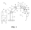
- the FIG. 1 shows an industrial robot R with a robot arm 1.
- the industrial robot R is designed in particular as a lightweight robot.
- the robot arm 1, which allows movement in six or seven degrees of freedom in the case of the present embodiment, essentially constitutes the movable part of the industrial robot R and comprises joints 2 to 5, levers 6 to 9 and a flange in a generally known manner 10, to which an end effector 33 can be attached.
- the joints 2-5 are each associated with respective axes with respect to which the links 6 to 9 can be rotatably moved.
- the industrial robot R can e.g. be designed as a medical industrial robot R.
- the end effector 33 is then e.g. designed as a medical instrument with which the industrial robot R can treat a living being P.
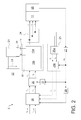
- Each of the joints 2-5 is powered by a regulated electric drive E, one of which in the Fig. 2 shown is moved.
- the electric drive E each have an electric motor 11 to 14.
- the motors 11-14 are eg AC motors, in particular three-phase motors.
- the motors 11-14 are synchronous motors, in particular permanent-magnet synchronous motors.
- the motors 11-14 are each preceded by a converter 15-18 or a three-phase inverter, which generates a three-phase alternating voltage of variable frequency from a DC voltage V, with which the corresponding motors 11-14 are acted upon.
- Inverters or inverters are in principle known to the person skilled in the art and comprise a power section 15a, for example three half-bridges, which are, for example, transistors, in particular MOSFETs include, and a drive electronics 15b.
- the inverters 15-18 are fastened to the respective motors 11-14, at least in or on the robot arm 1.
- the DC voltage V is provided in the case of the present embodiment by a single DC link 20 to which all inverters 15-18 are connected.
- the intermediate circuit 20 comprises e.g. a DC link capacitor and is in the case of the present embodiment part of a DC-DC converter 21, which is also referred to as a DC / DC converter.
- DC-DC converters are known in principle to the person skilled in the art and generate from a, e.g. by means of a rectifier 22 from the mains voltage smoothed DC voltage 23, the DC voltage V.
- the rectifier 22 and especially the DC-DC converter 21 are arranged in a control cabinet 24 in which e.g. also, a control device 19 of the industrial robot R is arranged.
- the control device 19 takes over in the case of the present embodiment, the control of the electric drives E.
- On the control device 19 runs a computer program that controls the operation of the industrial robot R, the electric drives E, in particular the inverter 15-18, so that the robot arm 1 and the flange 10 undergoes a predetermined movement.
- the spacer device 34 may also be provided a spacer device 34, as is the case in the case of the present embodiment.
- the spacer device 34 is connected in a manner not shown to the control device 19 and is arranged, a distance d between the end effector 33, in particular its tool center points TCP, and a critical structure, eg the surface of the living being P to determine.
- the electric drives E by means of field-oriented control, which is also referred to as vector control regulated.
- the electric motors 11-14 are replaced by e.g. speed or position controlled.
- the regulated electric drive E based in the case of the present embodiment on the principle known in the art field-oriented control, which is modified according to the claims.
- field-oriented control the three-phase currents and voltages are transformed into rotating current and voltage vectors and used for regulation.
- the control of the electric drive E is implemented in the control device 19 and the Fig. 2 shows functional blocks of this regulation.
- This regulation comprises, in particular, an electrical current regulation, which is embodied in particular as a subordinate regulation.
- the power part 15 a of the inverter 15 generates a three-phase voltage, which is supplied to the motor 11.
- a three-phase alternating current (three-phase) i 1,2,3 which is measured for example by means of a current measuring device 24.
- the measuring device 24 is in turn connected to a transformation device 25, which, as is known in the art in principle, initially transformed by means of a transformation block 25a, the measured three-phase motor currents in stator fixed current space vector with the components I ⁇ and I ⁇ , which synchronously with the Rotor of the engine 11 rotate.
- the stator-fixed current space vectors are subsequently transformed to the rotor-fixed d, q coordinate system by means of a further transformation block 25b, whereby the space vector components I d and I q are formed.
- This transformation comprises a rotation by an angle 2 p ⁇ (number of poles of the motor 11 multiplied by the mechanical rotor angle).
- the mechanical rotor angle is determined for example by means of a rotary encoder 26 and is multiplied by means of a scaling block 27 with the number of poles of the motor 11, whereby the electrical rotor angle ⁇ el arises.
- the space vector components I d, q are supplied to a current regulator 28, which is designed, for example, as a so-called PI regulator.
- a current regulator 28 which can be in particular an analog controller or a digital controller.
- the output of the scaling block 27 is fed to a low-pass filter 29, whose output signal can also be supplied to the current controller 28.
- Further input signals of the current controller 28 or the command values of the current regulator 28 are, in the case of the present exemplary embodiment, nominal values for the current-space vector components I d, soll and I q, soll .
- the target value for I d, soll is equal to zero.
- the output signals or the manipulated variables of the current controller 28 related to the rotor of the motor 11 voltages U d, q which are transformed by means of a transformation block 30 in the related to the stator of the motor 11 voltages U a, ⁇ .
- a transformation block 30 in the related to the stator of the motor 11 voltages U a, ⁇ .
- the transformation block 30 for dese transformation is in the case of the present embodiment nor the 180 ° phase shifted electrical rotor angle ⁇ el the transformation block 30, which is calculated by means of a phase rotation block 31.
- the voltages U ⁇ , ⁇ related to the stator of the motor 11 are the input signals of the converter 15 or its control electronics 15b, which drives the power section 15a of the converter 15 based on the pulse width modulation, for example, so that the latter desired three-phase voltage for the motor 11 generates.
- the control device 19 is embodied in the case of the present exemplary embodiment or the computer program for controlling the robot arm 1 running on the control device is designed such that the motor current i 1 , 2, 3 is monitored and / or limited.
- This is realized in particular by a dynamic adaptation of the current limitation, for example, to the working step of the workflow, in particular of a medical application, to the robot pose and / or the load parameters of the end effector 33 attached to the industrial robot R.
- This is also a reduction, if not minimizing the travel in case of failure while taking into account the momentarily required force and acceleration capacity of the robot R possible.
- control device 19 In order to limit the motor current i 1, 2, 3 dynamically or robot-application-specific, the control device 19 is embodied such that it dynamically limits the values of the command variables of the current controller 28 in a robot-application-specific manner. In particular, the control device 19 limits the value of the reference variable I q, should the current controller 28th
- control device 19 may be configured such that the robot application-specific dynamic limiting of the value of the reference variable I q, soll the current controller 28, for example, on a required speed of the tool center point TCP of the industrial robot R for the application and / or a step during the movement of the industrial robot R, a current pose of the industrial robot R, a safety requirement for the application and / or a work step during the movement of the industrial robot R, the distance d to the living being P, which is determined in particular by means of the distance measuring device 34, a required Force capacity for the application and / or a step during the movement of the industrial robot R, and / or a load parameter of the attached to the industrial robot R end effector 33 is used.
- control device 19 can also be designed in such a way that it first performs path planning in order to plan a movement of the industrial robot R. It then limits the value of the reference variable I q, should the current controller 28 due to the carried out path planning.
- control device 19 is designed to change the value of the command variable Iq, should of the current regulator 28 during the movement of the industrial robot R as a function of the path planning.
- control device 19 can also be designed such that it determines a maximum required value of the command variable I q, should the current controller 28 due to the path planning, in particular the highest speed request the train planning underlying movement of the industrial robot R or associated with the electric drive E member is associated. The control device 19 in particular then limits the value of the reference variable I q, the current controller 28 is to the maximum required value before performing the path planning associated movement of the industrial robot R.
- control device 19 can also be set up in such a way that it calculates the value of the command variable I q, soll of the current controller 28 corresponding to the path planning and during the execution of the path planning associated movement of the industrial robot R or with the electric drive E Moving member the value of the reference variable I q, the current controller 28 is dynamically limited during the movement of the industrial robot R, so varies according to the planned movement, the limit.
- control device 19 may also be set up to limit the value of the reference variable I q, of the current controller 28 to a maximum value based on a maximum permissible speed of the application associated with the movement prior to the movement of the industrial robot R. This maximum value is not exceeded during the movement.
- the adaptation of the reference variable I q, should the current controller 28 by the control device 19 may for example also be as follows:
- the required force capacity and the safety requirement for example the travel in case of error
- the current application and its operations for example transmitted in the form of a table in a secure technique to the control device 19.
- the load data of the end effector 33 used is transferred to the control device 19, in particular using secure technology.
- the joint angles of the industrial robot R are detected, in particular using secure technology, and both the currently fastened end effector 33 and the working step in the application workflow are identified. These data are transmitted to the control device 19, in particular using secure technology.
- control device 19 is set up to dynamically limit the value of the manipulated variables U d, q of the current controller 28 robotically, for example to limit the travel of the industrial robot R in the event of an error, ie to reduce movement of the robot arm 1 in the event of a fault.
- This is realized in particular by a dynamic adaptation of the manipulated variables U d, q of the current controller 28, for example, to the working step of the workflow, in particular of a medical application, to the robot pose and / or the load parameters of the end effector 33 attached to the industrial robot R. This is also a reduction, if not minimizing the travel in case of failure of the industrial robot R possible.
- control device 19 may be set up such that the robot application-specific dynamic limiting of the value of the manipulated variables U d, q of the current controller 28, for example, to a required speed of the tool center point TCP of the industrial robot R for the application and / or a step during the movement of the robot R, a current pose of the industrial robot R, a security request for the application and / or a Operating step during the movement of the robot R, the distance d to the living organism P, which is determined in particular by measurement by means of the distance measuring device 34, and / or a working step during the movement of the industrial robot R, and / or a load parameter of the attached to the industrial robot R end effector 33 based is placed.
- control device 19 can also be designed in such a way that it first performs path planning in order to plan a movement of the industrial robot R. It then limits the value of the manipulated variables U d, q of the current controller 28 on the basis of the path planning carried out.
- control device 19 is designed such that it changes the value of the manipulated variables U d, q of the current controller 28 during the movement of the robot R as a function of the path planning.
- control device 19 can also be designed such that it determines a maximum required value of the manipulated variables U d, q of the current controller 28 due to the path planning, in particular the highest speed requirement of the train planning underlying motion of the industrial robot R or the electric drive E is associated with a moving member.
- the control device 19 in particular then limits the value of the manipulated variables U d, q of the current regulator 28 to the maximum required value before the movement of the industrial robot R. associated with the path planning is carried out.
- control device 19 can also be set up in such a way that it calculates the value of the manipulated variables U d, q of the current controller 28 corresponding to the path planning and during the execution of the path planning associated movement of the industrial robot R or moving the electric drive E member dynamically limits the value of the manipulated variables U d, q of the current controller 28 during the movement of the industrial robot R, so according to the movement varies the limit.
- control device 19 may also be set up to limit the value of the manipulated variables U d, q of the current controller 28 to a maximum value based on a maximum permissible speed of the application associated with the movement prior to the movement of the industrial robot R. This maximum value is not exceeded during the movement.
- the adaptation of the manipulated variables U d, q of the current regulator 28 by the control device 19 can also be carried out, for example, as follows:
- the safety requirement for example the travel path in the event of a fault
- the control device 19 for the current application and its working steps, for example in the form of a table.
- the load data of the end effector 33 used is transferred to the control device 19, in particular using secure technology.
- the joint angles of the industrial robot R are detected, in particular using secure technology, and both the currently fastened end effector 33 and the working step in the application workflow are identified. These data are transmitted to the control device 19, in particular using secure technology.
- Manipulated variables U d, q of the current controller 28 should also be understood to be the value of the output signal of the transformation block 30.
Landscapes
- Engineering & Computer Science (AREA)
- Robotics (AREA)
- Mechanical Engineering (AREA)
- Manipulator (AREA)
Abstract
Description
Die Erfindung betrifft einen Roboter und ein Verfahren zum Betreiben eines Roboters.The invention relates to a robot and a method for operating a robot.
Ein Beispiel eines Roboters ist ein Industrieroboter. Diese sind Handhabungsmaschinen, die zur selbsttätigen Handhabung von Objekten mit zweckdienlichen Werkzeugen ausgerüstet und in mehreren Bewegungsachsen insbesondere hinsichtlich Orientierung, Position und Arbeitsablauf programmierbar sind. Industrieroboter weisen im Wesentlichen einen Roboterarm mit mehreren Achsen und Hebeln auf, die von geregelten elektrischen Antrieben bewegt werden. Die geregelten elektrischen Antriebe umfassen z.B. einen Synchronmotor, insbesondere einen permanent erregten Synchronmotor, der von einem Umrichter mittels einer Regelvorrichtung angesteuert wird. Im Fehlerfall soll die Bewegung des Roboters so schnell wie möglich gestoppt werden.An example of a robot is an industrial robot. These are handling machines that are equipped for the automatic handling of objects with appropriate tools and programmable in several axes of motion, in particular with regard to orientation, position and workflow. Industrial robots essentially have a robotic arm with multiple axes and levers that are moved by regulated electric drives. The regulated electric drives include e.g. a synchronous motor, in particular a permanently excited synchronous motor which is driven by a converter by means of a control device. In the event of a fault, the movement of the robot should be stopped as quickly as possible.
Aufgabe der Erfindung ist es, ein verbessertes Verfahren zum Betreiben eines Roboters anzugeben, aufgrund dessen der Verfahrweg des Roboters im Fehlerfall verringert werden kann.The object of the invention is to provide an improved method for operating a robot, due to which the travel of the robot can be reduced in case of failure.
Die Aufgabe der Erfindung wird gelöst durch ein Verfahren zum Betreiben eines Roboters, der wenigstens ein Glied, das gesteuert von einer Steuervorrichtung des Roboters mittels eines geregelten elektrischen Antriebs bewegbar ist, und der geregelte elektrische Antrieb einen zumindest indirekt mit dem Glied mechanisch gekoppelten Elektromotor, ein den Elektromotor ansteuerndes Stellglied und eine das Stellglied ansteuernde Regelvorrichtung umfasst, aufweisend ein roboterapplikationsspezifisches dynamisches Begrenzen des Wertes der Führungs- und/oder Stellgröße der Regelvorrichtung. Die Führungsgröße kann insbesondere dem zum Bewegen des Elektromotors vorgesehenen elektrischen Strom zugeordnet sein.The object of the invention is achieved by a method for operating a robot, which is at least one member, which is controlled by a control device of the robot by means of a regulated electric drive movable, and the controlled electric drive at least indirectly with the member mechanically coupled electric motor, a comprising the electric motor controlling actuator and the actuator controlling the control device comprising a robot application specific dynamic limiting the value of the control and / or manipulated variable of the control device. The reference variable may in particular be assigned to the electric current intended for moving the electric motor.
Ein weiterer Aspekt der Erfindung betrifft einen Roboter, aufweisend wenigstens ein Glied, das gesteuert von einer Steuervorrichtung des Roboters mittels eines geregelten elektrischen Antriebs bewegbar ist, und der geregelte elektrische Antrieb einen zumindest indirekt mit dem Glied mechanisch gekoppelten Elektromotor, ein den Elektromotor ansteuerndes Stellglied und eine das Stellglied ansteuernde Regelvorrichtung aufweist, deren Führungsgröße dem zum Bewegen des Elektromotors vorgesehenen elektrischen Strom zugeordnet ist, aufweist, und die Steuervorrichtung eingerichtet ist, den Wert der Führungs- und/oder Stellgröße der Regelvorrichtung gemäß dem erfindungsgemäßen Verfahren roboterapplikationsspezifisch dynamisch zu begrenzen.A further aspect of the invention relates to a robot, comprising at least one member, which is controlled by a control device of the robot by means of a regulated electric drive movable, and the regulated electric drive at least indirectly with the member mechanically coupled electric motor, an electric motor driving the actuator and a control device which actuates the control device whose reference variable is assigned to the electric current intended for moving the electric motor, and the control device is set up to dynamically limit the value of the control and / or manipulated variable of the control device in accordance with the method according to the invention.
Der Roboter kann vorzugweise ein Industrieroboter oder ein Leichtbauroboter sein. Der erfindungsgemäße Roboter kann insbesondere einen Roboterarm mit dem Glied und weiteren, nacheinander folgenden, mittels Gelenken verbundene Glieder, sowie weitere dem geregelten elektrischen Antrieb entsprechende elektrische Antriebe, deren Elektromotoren mit den weiteren Gliedern zumindest indirekt mechanisch gekoppelt sind, aufweisen, wobei die Steuervorrichtung eingerichtet ist, die Werte der Führungs- und/oder Stellgrößen der Regelvorrichtungen der weiteren geregelten elektrischen Antrieben gemäß dem erfindungsgemäßen Verfahrenroboter applikationsspezifisch dynamisch zu begrenzen.The robot may preferably be an industrial robot or a lightweight robot. The robot according to the invention may in particular have a robot arm with the member and further, successively connected members connected by means of joints, as well as further electrical drives corresponding to the regulated electrical drive, whose electric motors are at least indirectly mechanically coupled to the other members, wherein the control apparatus is set up to dynamically limit the values of the control and / or manipulated variables of the control devices of the further regulated electrical drives in accordance with the inventive robot according to the application.
Gemäß dem erfindungsgemäßen Verfahren wird das Glied mittels des geregelten elektrischen Antriebs bewegt. Mittels der Regelvorrichtung kann z.B. die Position des Gliedes geregelt werden. Die Führungsgröße der Regelvorrichtung ist vorzugsweise dem elektrischen Strom des Elektromotors zugeordnet, d.h. mittels der Führungsgröße der Regelvorrichtung wird insbesondere der elektrische Strom des elektrischen Motors geregelt. Da erfindungsgemäß die Führungsgröße und/oder die Stellgröße der Regelvorrichtung dynamisch bzw. applikationsspezifisch begrenzt werden, werden somit gegebenenfalls auch der maximale elektrische Strom und/oder gegebenenfalls die maximale Versorgungsspannung des Elektromotors dynamisch bzw. applikationsspezifisch begrenzt. Somit wird erreicht, dass beispielsweise im Fehlerfall gegebenenfalls der Verfahrweg des Roboters verringert wird bei gegebenenfalls gleichzeitiger Berücksichtigung beispielsweise der momentan erforderlichen Kraft- und Beschleunigungskapazität des Roboters.According to the method of the invention, the member is moved by means of the regulated electric drive. By means of the control device, for example, the position of the member can be regulated. The reference variable of the regulating device is preferably associated with the electric current of the electric motor, ie by means of the reference variable of the regulating device, in particular the electric current of the electric motor regulated. Since, according to the invention, the reference variable and / or the manipulated variable of the control device are dynamically or application-specifically limited, the maximum electric current and / or, if applicable, the maximum supply voltage of the electric motor may also be limited dynamically or application-specific. Thus, it is achieved that, for example, in case of error, if appropriate, the travel of the robot is reduced, possibly taking into account simultaneously, for example, the currently required force and acceleration capacity of the robot.
Der roboterapplikationsspezifischen dynamischen Begrenzung des Wertes der Führungs- und/oder Stellgröße der Regelvorrichtung kann beispielsweise eine erforderliche Geschwindigkeit eines Tool Center Points des Roboters für die Applikation und/oder einem Arbeitsschritt während der Bewegung des Roboters, einer aktuellen Pose des Roboters, einer Sicherheitsanforderung für die Applikation und/oder einem Arbeitsschritt während der Bewegung des Roboters, einem Abstand zu einer kritischen externen Struktur, der insbesondere messtechnisch ermittelt wird, einer erforderlichen Kraftkapazität für die Applikation und/oder einem Arbeitsschritt während der Bewegung des Roboters, und/oder einem Lastparameter eines am Roboter befestigten Instruments zugrunde gelegt werden.The robot application-specific dynamic limitation of the value of the control and / or manipulated variable of the control device may, for example, a required speed of a tool center point of the robot for the application and / or a step during the movement of the robot, a current pose of the robot, a security requirement for the Application and / or a step during the movement of the robot, a distance to a critical external structure, which is determined in particular by measurement, a required force capacity for the application and / or a step during the movement of the robot, and / or a load parameter of the Robotic instrument attached.
Der geregelte elektrische Antrieb umfasst das Stellglied, das insbesondere eine elektrische Spannung zum Antreiben des Elektromotors erzeugt. Dann kann vorzugsweise die Stellgröße der Regelvorrichtung dieser elektrischen Spannung zugeordnet sein. Geeignete Stellglieder sind z.B. Umrichter oder Wechselrichter.The regulated electric drive comprises the actuator, which in particular generates an electrical voltage for driving the electric motor. Then, preferably, the manipulated variable of the control device associated with this electrical voltage. Suitable actuators are, for example, inverters or inverters.
Der geregelte elektrische Antrieb kann eine innere und eine äußere Regelschleife umfassen. Dann ist die Regelvorrichtung vorzugsweise Teil der inneren Regelschleife.The regulated electric drive may include an inner and an outer control loop. Then the control device is preferably part of the inner control loop.
Der Elektromotor kann gemäß einer Variante des erfindungsgemäßen Verfahrens bzw. des erfindungsgemäßen Roboters ein Wechselstrommotor sein. Der Wechselstrommotor kann insbesondere ein Drehstrommotor und/oder ein Synchronmotor sein. Als Synchronmotor kann vorzugsweise ein permanent erregter Synchronmotor verwendet werden. Wird ein Drehstrommotor verwendet, dann kann der elektrische Antrieb vorzugsweise basierend auf der feldorientierten Regelung geregelt werden.The electric motor may be an AC motor according to a variant of the method according to the invention or of the robot according to the invention. The AC motor may in particular be a three-phase motor and / or a synchronous motor. As a synchronous motor can preferably be used a permanently excited synchronous motor. If a three-phase motor is used, then the electric drive can preferably be regulated based on the field-oriented control.
Es ist aber auch möglich, dass als Elektromotor ein Gleichstrommotor verwendet wird. Dann kann vorzugsweise die Regelvorrichtung bzw. der geregelte elektrische Antrieb auf dem Stromleitverfahren basieren.But it is also possible that a DC motor is used as the electric motor. Then, preferably, the control device or the regulated electric drive based on the Stromleitverfahren.
Gemäß einer Ausführungsform des erfindungsgemäßen Verfahrens weist dieses folgende Verfahrensschritte:
- Durchführen einer Bahnplanung mittels der Steuervorrichtung des Roboters, um eine Bewegung des Roboters zu planen, und
- Begrenzen des Werts der Führungs- und/oder Stellgröße der Regelvorrichtung aufgrund der von der Steuervorrichtung durchgeführten Bahnplanung.
- Performing a path planning by means of the control device of the robot to plan a movement of the robot, and
- Limiting the value of the control and / or manipulated variable of the control device due to the path planning carried out by the control device.
Gemäß dieser Ausführungsform ist es gegebenenfalls vorgesehen, den Wert der Führungsgröße und/oder der Stellgröße der Regelvorrichtung während der Bewegung des Roboters in Abhängigkeit von der Bahnplanung zu ändern, insbesondere zu regeln. Je nach Applikation kann somit gegebenenfalls der maximal erlaubte Wert des Motorstroms zur Laufzeit der Bewegung des Roboters variiert werden. Bei geplanten Bewegungen, bei denen z.B. die Achswinkelgeschwindigkeit in Abhängigkeit der Zeit bekannt sind, kann damit auch die Abhängigkeit der maximal notwendigen elektrischen Spannung von der Zeit ermittelt und damit auch vorgesteuert werden.According to this embodiment, it is optionally provided to change the value of the reference variable and / or the manipulated variable of the control device during the movement of the robot in dependence on the path planning, in particular to regulate. Depending on the application, the maximum permissible value of the motor current may therefore be varied during runtime of the movement of the robot. For planned movements, in which, for example, the Achswinkelgeschwindigkeit are known as a function of time, so that the dependence of the maximum necessary electrical voltage can be determined by the time and thus also be pre-controlled.
Nach einer weiteren Variante des erfindungsgemäßen Verfahrens kann dieses ein Bestimmen eines aufgrund der Bahnplanung maximal benötigten Wertes der Führungs- und/oder Stellgröße der Regelvorrichtung aufweisen, der insbesondere der höchsten Geschwindigkeitsanforderung der der Bahnplanung zugrunde gelegten Bewegung des Roboters oder des mit dem elektrischen Antrieb bewegten Gliedes zugeordnet ist, und ein Begrenzen des Wertes der Führungs- und/oder Stellgröße der Regelvorrichtung auf den maximal benötigten Wert der Führung- und/oder Stellgröße der Regelvorrichtung vor der Durchführung der der Bahnplanung zugeordneten Bewegung des Roboters erfolgen.According to a further variant of the method according to the invention, this can comprise determining a maximum required value of the control and / or manipulated variable of the control device due to the path planning, in particular the highest speed requirement of the movement planning of the robot or the member moved with the electric drive is assigned, and limiting the value of the control and / or manipulated variable of the control device to the maximum required value of the control and / or manipulated variable of the control device before performing the path planning associated movement of the robot done.
Im Rahmen dieser Variante des erfindungsgemäßen Verfahrens kann ein Berechnen für die Bahnplanung entsprechender Werte der Führungs- und/oder Stellgröße der Regelvorrichtung und während der Durchführung der der Bahnplanung zugeordneten Bewegung des Roboters oder des mit dem elektrischen Antrieb bewegten Gliedes und entsprechend ein Begrenzen des Wertes der Führungs- und/oder Stellgröße der Regelvorrichtung während der Bewegung vorgesehen sein.In the context of this variant of the method according to the invention can be calculated for the path planning of appropriate values of the control and / or manipulated variable of the control device and during the implementation of the web planning associated movement of the robot or moving the electric drive member and accordingly limiting the value of the Guiding and / or manipulated variable of the control device may be provided during the movement.
Nach einer weiteren Ausführungsform des erfindungsgemäßen Verfahrens weist dieses ein Begrenzen des Wertes der Führungs- und/oder Stellgröße der Regelvorrichtung auf einen Maximalwert aufgrund einer maximal zulässigen Nutzlast und/oder Geschwindigkeit der der Bewegung zugeordneten Applikation vor der Bewegung auf. Gemäß dieser Ausführungsform wird demnach vor Beginn der Applikation der Maximalwert der Führungs- und/oder Stellgröße basierend auf der während der Applikation zulässigen maximalen Nutzlast und/oder Geschwindigkeit limitiert. Diese Begrenzungen können für unterschiedliche Arbeitsschritte innerhalb des applikationsspezifischen Workflows auf unterschiedliche Werte festgelegt werden. Der Geschwindigkeitsmaximalwert wird während der Bewegung nicht überschritten. Somit wird sicher gestellt, dass das vom Elektromotor bewegte Glied bzw. die von den Elektromotoren bewegten Glieder die maximale Geschwindigkeit nicht überschreiten können.According to a further embodiment of the method according to the invention, this has a limiting of the value of the control and / or manipulated variable of the control device to a maximum value due to a maximum allowable payload and / or speed of the application associated with the movement prior to the movement. According to this embodiment, therefore, before the start of the application, the maximum value of the control and / or manipulated variable based on the during the Application permissible maximum payload and / or speed limited. These limits can be set to different values for different work steps within the application-specific workflow. The maximum speed value is not exceeded during the movement. This ensures that the member moved by the electric motor or the members moved by the electric motors can not exceed the maximum speed.
Die Steuerungsarchitektur des erfindungsgemäßen Roboters kann folgendermaßen realisiert sein: Die Stromregelung erfolgt auf der Antriebselektronik. Gegebenfalls eine übergeordnete Regelung, z.B. Positionsregelung kann auf einer separaten übergeordneten Recheneinheit erfolgen. Gegebenfalls die Berechnung der Stromgrenzen, d.h. die Berechnung des Maximalwertes der Führungsgröße kann vorzugsweise in sicherer Technik erfolgen, beispielsweise auf einer Sicherheitssteuerung des Roboters.The control architecture of the robot according to the invention can be realized as follows: The current regulation takes place on the drive electronics. Optionally, a higher level control, e.g. Position control can be carried out on a separate superordinate arithmetic unit. Optionally, the calculation of the current limits, i. the calculation of the maximum value of the command variable can preferably be done in a secure technique, for example on a safety control of the robot.
Die Anpassung der Führungsgröße der Regelvorrichtung kann beispielsweise folgendermaßen erfolgen, wenn der erfindungsgemäße Roboter z.B. als medizinischer Roboter ausgeführt ist:The adaptation of the reference variable of the control device can, for example, be carried out as follows, if the robot according to the invention is e.g. designed as a medical robot:
Vor Beginn einer medizinischen Operation mit dem Roboter wird die erforderliche Kraftkapazität und die Sicherheitsanforderung, beispielsweise der Verfahrweg im Fehlerfall, für die aktuelle Applikation und deren Arbeitsschritte beispielsweise in Form einer Tabelle in sicherer Technik (z.B. über FSoE) an die Sicherheitssteuerung übermittelt. Ebenso werden die Lastdaten der verwendeten Instrumente in sicherer Technik an die Sicherheitssteuerung übergeben.Before the start of a medical operation with the robot, the required force capacity and the safety requirement, for example the trajectory in the event of a fault, are transmitted to the safety control for the current application and its work steps, for example in the form of a table in secure technology (eg via FSoE). Likewise, the load data of the instruments used is transferred to the safety controller using safe technology.
Während der Operation werden in sicherer Technik die Gelenkwinkel des Roboters erfasst und sowohl das momentan befestigte Instrument (z.B. durch instrumentenspezifische Kontaktmatrix oder RFID) als auch der Arbeitsschritt im Applikations-Workflow (z.B. durch Betätigung von sicheren Zustimmtastern) identifiziert. Diese Daten werden in sicherer Technik an die Sicherheitssteuerung übermittelt.During the operation, the robot's joint angles are detected in a secure technique and both the currently mounted instrument (e.g., by instrument specific contact matrix or RFID) and the operation in the application workflow (e.g., by activating secure consent buttons) are identified. These data are transmitted to the safety controller using secure technology.
Es können die Stromgrenzen für die einzelnen Motoren in den Gelenken auf der Sicherheitssteuerung ermittelt werden. Dies kann beispielsweise über eine Rechenvorschrift oder über eine zuvor ermittelte Tabelle erfolgen.The current limits for the individual motors in the joints on the safety control can be determined. This can be done for example via a calculation rule or via a previously determined table.
Es ist auch möglich, den Abstand des TCPs des Roboters zu einer kritischen Struktur messtechnisch zu erfassen und als Eingangsvariable zur Ermittlung der Stromgrenzen auf der Sicherheitssteuerung zu verwenden.It is also possible to metrologically record the distance of the TCP of the robot to a critical structure and to use it as an input variable for determining the current limits on the safety controller.
Es kann eine sichere Übertragung der Stromgrenzen an die Antriebselektroniken vorgesehen sein.It can be provided for a safe transmission of the current limits to the drive electronics.
Es kann eine nichtsichere Übertragung der Stromgrenzen an die übergeordnete Steuerungseinheit, wenn vorgesehen, vorgesehen sein. Eine sicherheitsgerichtete Übertragung kann z.B. dann nicht notwendig sein, wenn die übergeordnete Steuerung nicht in sicherer Technik realisiert ist.It may be a non-secure transmission of the current limits to the parent control unit, if provided, provided. A safety-related transmission can e.g. then not be necessary if the higher-level control is not implemented in safe technology.
Die dynamische Begrenzung der Führungsgröße und somit des Motorstroms kann z.B. folgendermaßen realisiert werden:The dynamic limitation of the command variable, and thus of the motor current, may be e.g. be realized as follows:
Begrenzung der Soll-Ströme durch angepasste Steuerungsalgorithmen auf der übergeordneten, insbesondere nicht sicherheitsgerichteten, Recheneinheit der Steuervorrichtung. Somit kann eine Erhöhung der Verfügbarkeit erreicht werden, da bei Verletzung der Begrenzung der kommandierten Ströme auf der Antriebselektronik ein Notstopp eingeleitet werden kann. Auf der Antriebselektronik kann eine Prüfung der durch die übergeordnete Recheneinheit berechneten Soll-Ströme auf Einhaltung der Stromgrenze vorgesehen sein. Eine Einleitung eines Notstopps bei Verletzung der Stromgrenze kann ebenfalls vorgesehen sein.Limiting the desired currents by means of adapted control algorithms on the higher-level, in particular not safety-oriented, arithmetic unit of the control device. Thus, an increase in availability can be achieved because at Violation of the limitation of the commanded currents on the drive electronics an emergency stop can be initiated. On the drive electronics, a check of the calculated by the superordinate arithmetic unit set currents to comply with the current limit can be provided. An initiation of an emergency stop if the current limit is violated may also be provided.
Es kann gegebenenfalls eine Prüfung des vorzugsweise in sicherer Technik gemessenen Ist-Stroms auf der Antriebselektronik auf Einhaltung der Stromgrenze vorgesehen sein. Eine Einleitung eines Notstopps kann bei Verletzung der Stromgrenze durchgeführt werden.If appropriate, a check of the actual current, which is preferably measured using safe technology, may be provided on the drive electronics for compliance with the current limit. An initiation of an emergency stop can be carried out if the current limit is violated.
Es kann der erwartete Ist-Strom auf der Antriebselektronik unter Verwendung eines Modells der Regelvorrichtung bzw. des entsprechenden Stromregelkreises berechnet werden. Ein Vergleich des erwarteten Ist-Stroms mit dem gemessenen Ist-Strom kann vorgenommen werden. Eine Einleitung eines Notstopps bei Überschreitung einer definierten Abweichung kann vorgesehen sein.The expected actual current on the drive electronics can be calculated using a model of the control device or the corresponding current control loop. A comparison of the expected actual current with the measured actual current can be made. An initiation of an emergency stop when exceeding a defined deviation can be provided.
Es kann der tatsächliche Ist-Strom mittels elektrischer Sicherung begrenzt werden.The actual current can be limited by means of electrical fuse.
Je nach Ausführungsform erreicht man mit dem erfindungsgemäßen Verfahren, dass der Verfahrweg des Roboters im Fehlerfall beispielsweise mittels dynamisch limitierbarer physikalischer Begrenzung der Abtriebsgeschwindigkeit der einzelnen Achsen begrenzt wird. Diese können vorzugsweise derart limitiert werden, sodass die Bewegungsgeschwindigkeit des Roboters den Erfordernissen der aktuellen Applikation angepasst ist. Diese Limitierung kann bei bekannten Bewegungen, wie z.B. Fräsen, auch während der Laufzeit der Applikation variiert werden, um z.B. die Geschwindigkeit der einzelnen Achsen immer auf die maximal notwendige Geschwindigkeit zu limitieren.Depending on the embodiment, with the method according to the invention, the travel of the robot in the event of a fault is limited, for example, by means of dynamically limited physical limitation of the output speed of the individual axes. These can preferably be limited in such a way that the movement speed of the robot is adapted to the requirements of the current application. This limitation can be varied in known movements, such as milling, during the life of the application, for example, the speed of the individual axes always limit to the maximum necessary speed.
Bei Applikationen, bei denen die genaue Bewegung zur Laufzeit noch nicht bekannt ist, kann die Bewegungsgeschwindigkeit zu Beginn auf einen maximalen, für diese Applikation sinnvollen Wert gesetzt werden. Beispielsweise bei der groben Vorpositionierung dürfen die maximalen Geschwindigkeiten relativ hoch, bei der Feinpositionierung des Endeffektors des Roboters jedoch nur relativ gering sein.In applications where the exact movement is not yet known at runtime, the movement speed can initially be set to a maximum value that is appropriate for this application. For example, in the rough pre-positioning the maximum speeds may be relatively high, but in the fine positioning of the end effector of the robot to be relatively low.
Das erfindungsgemäße Verfahren bietet gegebenenfalls eine dynamische Anpassung der physikalischen Begrenzung der maximalen Geschwindigkeit des TCPs. Applikationsabhängig kann diese Beschränkung sogar noch zur Laufzeit der Applikation möglich sein, beispielsweise bei geplanten Bewegungen.If appropriate, the method according to the invention offers a dynamic adaptation of the physical limitation of the maximum speed of the TCP. Depending on the application, this restriction may even be possible during the runtime of the application, for example during planned movements.
Mögliche Einflussgrößen für die Anpassung der Abtriebsgeschwindigkeit der einzelnen Achsen sind beispielsweise erforderliche Geschwindigkeit des TCP für Applikation und Arbeitsschritt, aktuelle Pose des Roboters, Sicherheitsanforderung für die aktuelle Applikation und des aktuellen Arbeitsschritts, ein Abstand zu einer kritischen Struktur, der insbesondere messtechnisch erfasst wird.Possible influencing variables for adapting the output speed of the individual axes are, for example, the required speed of the TCP for application and work step, current pose of the robot, safety requirement for the current application and the current work step, a distance to a critical structure, which is detected in particular by measurement.
Ist die Stellgröße der Regelvorrichtung der elektrischen Spannung des Motors, insbesondere dessen Soll-Spannung, zugeordnet, dann können im Falle einer gewollten Begrenzung der Drehzahl des Motors auf eine maximale Drehzahl, insbesondere eine dynamischen Beschränkung der maximalen Motorspannung, die von der Regelvorrichtung berechneten Spannungssollwerte, d.h. die Stellgrößen der Regelvorrichtung, auf einen dynamisch einstellbaren Wert überwacht bzw. begrenzt werden. Die Geschwindigkeitsgrenzen können vorzugsweise in sicherer Technik auf der gegebenenfalls vorhandenen Sicherheitssteuerung der Steuerungsvorrichtung erfolgen.If the manipulated variable of the control device is associated with the electrical voltage of the motor, in particular its nominal voltage, then in the case of an intentional limitation of the speed of the motor to a maximum speed, in particular a dynamic limitation of the maximum motor voltage, the voltage setpoints calculated by the control device, ie the manipulated variables of the control device are monitored or limited to a dynamically adjustable value. The speed limits may preferably be done in safe technology on the possibly existing safety control of the control device.
Die Begrenzung der Spannungsbegrenzung, d.h. für diese Ausführungsform die Begrenzung der Stellgröße der Regelvorrichtung kann z.B. folgendermaßen realisiert werden:
- Vor Beginn oder auch während einer Applikation, insbesondere einer Operation im Falle eines als medizinischen Roboter ausgeführten Roboters wird die erforderliche Geschwindigkeit und/oder die Sicherheitsanforderung, beispielsweise der Verfahrweg im Fehlerfall, für die Applikation und deren Arbeitsschritte beispielsweise in Form einer Tabelle in sicherer Technik an die Steuervorrichtung, gegebenenfalls an deren Sicherheitssteuerung übermittelt.
- Während der Applikation, gegebenenfalls der Operation, werden insbesondere in sicherer Technik die Gelenkwinkel des Roboters erfasst und sowohl das momentan befestigte Instrument z.B. durch instrumentenspezifische Kontaktmatrix oder RFID als auch der Arbeitsschritt im Applikations-workflow z.B. durch Betätigung von sicheren Zustimmtastern identifiziert. Diese Daten werden insbesondere in sicherer Technik an die Steuervorrichtung, gegebenenfalls deren Sicherheitssteuerung übermittelt.
- Geschwindigkeitsgrenzen für die einzelnen Motoren werden in den Gelenken vorzugsweise auf der Sicherheitssteuerung ermittelt. Diese kann beispielsweise über eine Rechenvorschrift oder über eine zuvor ermittelte Tabelle erfolgen.
- In einer bevorzugten Ausführung kann der Abstand des TCPs zu einer kritischen Struktur messtechnisch erfasst und als Eingangsvariable zur Ermittlung der Geschwindigkeitsbeschränkung auf der Sicherheitssteuerung verwendet.
- Eine sichere Übertragung der Geschwindigkeitsgrenzen kann an die Antriebselektroniken erfolgen.
- Eine nichtsichere Übertragung der Geschwindigkeitsgrenzen kann an eine gegebenenfalls vorhandene übergeordnete Steuerungseinheit erfolgen.
- Before the beginning or else during an application, in particular an operation in the case of a robot designed as a medical robot, the required speed and / or safety requirement, for example the travel in the event of a fault, for the application and its work steps, for example in the form of a table in safe technology the control device, optionally transmitted to the safety control.
- During the application, if necessary, the operation, the joint angle of the robot are detected in particular safe technique and identifies both the currently attached instrument eg instrument specific contact matrix or RFID and the step in the application workflow eg by pressing secure consent buttons. These data are transmitted in particular in secure technology to the control device, possibly their safety control.
- Speed limits for the individual motors are determined in the joints, preferably on the safety control. This can be done for example via a calculation rule or via a previously determined table.
- In a preferred embodiment, the distance of the TCP to a critical structure can be measured and used as an input variable for determining the speed limit on the safety controller.
- Safe transmission of the speed limits can be done to the drive electronics.
- A non-secure transmission of the speed limits can be done to an optionally existing higher-level control unit.
Für die Variante, gemäß derer die Stellgröße der Regelvorrichtung der Motorspannung zugeordnet ist, kann z.B. die Begrenzung der Stellgröße, die vorzugsweise auf der Sicherheitssteuerung und vorzugsweise in sicherer Technik an die Regelvorrichtung übertragen wird, wie folgt erfolgen:For the variant according to which the manipulated variable of the control device is assigned to the motor voltage, e.g. the limitation of the manipulated variable, which is preferably transmitted to the control device on the safety control and preferably in safe technology, takes place as follows:
Der Spannungssollwerte der Regelvorrichtung, d.h. deren Stellgröße wird überwacht und begrenzt. Diese Beschränkung kann vor oder während der Laufzeit der Applikation getrennt für jede Achse gesetzt werden. Die aktuelle Spannungsgrenze kann von der übergeordneten Sicherheitssteuerung mittels angepasster Algorithmen errechnet werden. Um die Dynamik der Regelvorrichtung nicht unnötig einzuschränken, kann die Beschränkung vorzugsweise so ausgelegt werden, dass sie für einen relativ kurzen Zeitraum die Überschreitung der Grenzspannung erlaubt, z.B. für die Dauer des Einschwingvorganges des elektrischen Stromes.The voltage setpoints of the control device, i. their manipulated variable is monitored and limited. This restriction can be set separately for each axis before or during runtime of the application. The current voltage limit can be calculated by the higher-level safety controller by means of adapted algorithms. In order not to unnecessarily limit the dynamics of the control device, the restriction may be preferably designed to allow the limit voltage to be exceeded for a relatively short period of time, e.g. for the duration of the transient process of the electric current.
Ausführungsbeispiele der Erfindung sind exemplarisch in den beigefügten schematischen Zeichnungen dargestellt. Es zeigen:
- Fig. 1
- einen Industrieroboter mit mehreren Gliedern, die mittels geregelter elektrischer Antriebe bewegbar sind, und
- Fig. 2
- einen der geregelten elektrischen Antriebe.
- Fig. 1
- an industrial robot having a plurality of links, which are movable by means of controlled electrical drives, and
- Fig. 2
- one of the regulated electric drives.
Die
Der Industrieroboter R kann z.B. als medizinischer Industrieroboter R ausgebildet sein. Der Endeffektor 33 ist dann z.B. als medizinisches Instrument ausgebildet, mit dem der Industrieroboter R ein Lebewesen P behandeln kann.The industrial robot R can e.g. be designed as a medical industrial robot R. The
Jedes der Gelenke 2-5 wird mit einem geregelten elektrischen Antrieb E, von denen einer in der
Den Motoren 11-14 sind jeweils ein Umrichter 15-18 bzw. ein Drehstrom-Wechselrichter vorgeschaltet, der aus einer Gleichspannung V eine dreiphasige Wechselspannung variabler Frequenz erzeugt, mit der die entsprechenden Motoren 11-14 beaufschlagt werden. Wechselrichter bzw. Umrichter sind dem Fachmann im Prinzip bekannt und umfassen einen Leistungsteil 15a, z.B. drei Halbbrücken, die beispielsweise Transistoren, insbesondere MOSFETs umfassen, und eine Ansteuerelektronik 15b.The motors 11-14 are each preceded by a converter 15-18 or a three-phase inverter, which generates a three-phase alternating voltage of variable frequency from a DC voltage V, with which the corresponding motors 11-14 are acted upon. Inverters or inverters are in principle known to the person skilled in the art and comprise a
Im Falle des vorliegenden Ausführungsbeispiels sind die Umrichter 15-18 an den jeweiligen Motoren 11-14, zumindest im oder am Roboterarm 1 befestigt.In the case of the present exemplary embodiment, the inverters 15-18 are fastened to the respective motors 11-14, at least in or on the
Die Gleichspannung V wird im Fall des vorliegenden Ausführungsbeispiels von einem einzigen Zwischenkreis 20 bereitgestellt, mit dem alle Umrichter 15-18 verbunden sind. Der Zwischenkreis 20 umfasst z.B. einen Zwischenkreiskondensator und ist im Falle des vorliegenden Ausführungsbeispiels Teil eines Gleichspannungswandlers 21, der auch als DC/DC Konverter bezeichnet wird. Gleichspannungswandler sind dem Fachmann im Prinzip bekannt und erzeugen aus einer z.B. mittels eines Gleichrichters 22 aus der Netzspannung geglätteten Gleichspannung 23 die Gleichspannung V.The DC voltage V is provided in the case of the present embodiment by a
Im Falle des vorliegenden Ausführungsbeispiels sind der Gleichrichter 22 und vor allem der Gleichspannungswandler 21 in einem Steuerschrank 24 angeordnet, in dem z.B. auch eine Steuervorrichtung 19 des Industrieroboters R angeordnet ist. Die Steuervorrichtung 19 übernimmt im Falle des vorliegenden Ausführungsbeispiels auch die Regelung der elektrischen Antriebe E. Auf der Steuervorrichtung 19 läuft ein Rechenprogramm, das im Betrieb des Industrieroboters R die elektrischen Antriebe E, insbesondere die Umrichter 15-18 ansteuert, sodass der Roboterarm 1 bzw. der Flansch 10 eine vorbestimmte Bewegung durchläuft.In the case of the present embodiment, the
Es kann auch eine Abstandsvorrichtung 34 vorgesehen sein, wie dies im Falle des vorliegenden Ausführungsbeispiels der Fall ist. Die Abstandsvorrichtung 34 ist in nicht dargestellter Weise mit der Steuervorrichtung 19 verbunden und ist eingerichtet, einen Abstand d zwischen dem Endeffektor 33, insbesondere dessen Tool Center Points TCP, und einer kritischen Struktur, z.B. der Oberfläche des Lebewesens P zu ermitteln.It may also be provided a
Im Falle des vorliegenden Ausführungsbeispiels werden die elektrischen Antriebe E mittels feldorientierter Regelung, die auch als Vektorregelung bezeichnet wird, geregelt. Je nach Ausführung werden die elektrischen Motoren 11-14 z.B. drehzahl- oder positionsgeregelt. Die geregelten elektrischen Antrieb E basieren im Falle des vorliegenden Ausführungsbeispiels auf der im Prinzip dem Fachmann bekannten feldorientierten Regelung, die jedoch gemäß den Ansprüchen modifiziert ist. Bei der feldorientierten Regelung werden die dreiphasigen Ströme und Spannungen in rotierende Strom-und Spannungszeiger transformiert und für die Regelung verwendet.In the case of the present embodiment, the electric drives E by means of field-oriented control, which is also referred to as vector control regulated. Depending on the design, the electric motors 11-14 are replaced by e.g. speed or position controlled. The regulated electric drive E based in the case of the present embodiment on the principle known in the art field-oriented control, which is modified according to the claims. In field-oriented control, the three-phase currents and voltages are transformed into rotating current and voltage vectors and used for regulation.
Im Falle des vorliegenden Ausführungsbeispiels ist beispielsweise die Regelung des elektrischen Antriebs E in der Steuervorrichtung 19 implementiert und die
Wie bereits obenstehend beschrieben, erzeugt der Leistungsteil 15a des Umrichters 15 eine dreiphasige Spannung, welche dem Motor 11 zugeführt wird. Somit fließt durch die Wicklungen des Motors 11 ein dreiphasiger Wechselstrom (Drehstrom) i1,2,3, der z.B. mittels einer Strommessvorrichtung 24 gemessen wird. Die Messvorrichtung 24 ist wiederum mit einer Transformationsvorrichtung 25 verbunden, die, wie es dem Fachmann im Prinzip bekannt ist, zunächst mittels eines Transformationsblocks 25a die gemessenen dreiphasigen Motorströme in statorfeste Strom-Raumzeiger mit den Komponenten Iα und Iβ transformiert, die synchron mit dem Rotor des Motors 11 rotieren. Um die Größen auf den Rotor des Motors 11 zu beziehen, werden die statorfesten Strom-Raumzeiger auf das rotorfeste d, q-Koordinatensystem anschließend mittels eines weiteren Transformationsblock 25b transformiert, wodurch die Raumzeigerkomponenten Id und Iq entstehen. Diese Transformation umfasst eine Verdrehung um einen Winkel 2p ϕ (Polzahl des Motors 11 multipliziert mit dem mechanischen Läuferwinkel). Der mechanische Läuferwinkel wird beispielsweise mittels eines Drehgebers 26 ermittelt und wird mittels eines Skalierungsblocks 27 mit der Polzahl des Motors 11 multipliziert, wodurch der elektrische Läuferwinkel ϕel entsteht.As already described above, the
Im Falle des vorliegenden Ausführungsbeispiels werden die Raumzeigerkomponenten Id,q einem Stromregler 28 zugeführt, der z.B. als sogenannter PI-Regler ausgeführt ist. Dieser kann insbesondere ein analoger Regler oder auch ein digitaler Regler sein. Außerdem kann, wie es im Falle des vorliegenden Ausführungsbeispiels der Fall ist, das Ausgangssignal des Skalierungsblocks 27 einem Tiefpassfilter 29 zugeführt, dessen Ausgangssignal ebenfalls dem Stromregler 28 zugeführt werden kann.In the case of the present exemplary embodiment, the space vector components I d, q are supplied to a
Weitere Eingangssignale des Stromreglers 28 bzw. die Führungsgrößen des Stromreglers 28 sind im Falle des vorliegenden Ausführungsbeispiels Soll-Werte für die Strom-Raumzeigerkomponenten Id, soll und Iq, soll. Im Falle des vorliegenden Ausführungsbeispiels ist der Soll-Wert für Id, soll gleich Null.Further input signals of the
Im Falle des vorliegenden Ausführungsbeispiels sind die Ausgangssignale bzw. die Stellgrößen des Stromreglers 28 auf den Rotor des Motors 11 bezogene Spannungen Ud,q, die mittels eines Transformationsblocks 30 in den auf den Stator des Motors 11 bezogene Spannungen Ua,β transformiert werden. Für dese Transformation wird im Falle des vorliegenden Ausführungsbeispiels noch der um 180° Phasen verschobene elektrische Läuferwinkel ϕel dem Transformationsblock 30 zugeführt, der mittels eines Phasendrehblocks 31 berechnet wird.In the case of the present embodiment, the output signals or the manipulated variables of the
Die auf den Stator des Motors 11 bezogene Spannungen Uα,β sind im Falle des vorliegenden Ausführungsbeispiels die Eingangssignale des Umrichters 15 bzw. dessen Ansteuerelektronik 15b, welche z.B. basierend der Puls-Weiten-Modulation den Leistungsteil 15a des Umrichters 15 ansteuert, sodass dieser die gewollte dreiphasige elektrische Spannung für den Motor 11 erzeugt.In the case of the present exemplary embodiment, the voltages U α, β related to the stator of the
Um z.B. den Verfahrweg des Industrieroboters R in einem Fehlerfall, d.h. eine Bewegung des Roboterarms 1 im Fehlerfall zu verringern, ist im Falle des vorliegenden Ausführungsbeispiels die Steuervorrichtung 19 derart ausgeführt bzw. ist das auf der Steuervorrichtung laufende Rechenprogramm zum Steuern des Roboterarms 1 derart ausgeführt, dass der Motorstrom i1,2,3 überwacht und/oder begrenzt wird. Dies wird insbesondere durch eine dynamische Anpassung der Strombegrenzung beispielsweise an den Arbeitsschritt des Workflows insbesondere einer medizinischen Applikation, an die Roboterpose und/oder die Lastparameter des am Industrieroboter R befestigten Endeffektors 33 realisiert. Hierbei ist auch eine Verkleinerung, wenn nicht gar Minimierung des Verfahrwegs im Fehlerfall bei gleichzeitiger Berücksichtigung der momentan erforderlichen Kraft- und Beschleunigungskapazität des Roboters R möglich.For example, in order to reduce the travel of the industrial robot R in the event of a fault, ie a movement of the
Um den Motorstrom i1,2,3 dynamisch bzw. roboterapplikationsspezifisch zu begrenzen, ist die Steuervorrichtung 19 derart ausgeführt, dass sie die Werte der Führungsgrößen des Stromreglers 28 roboterapplikationsspezifisch dynamisch begrenzt. Insbesondere begrenzt die Steuervorrichtung 19 den Wert der Führungsgröße Iq, soll des Stromreglers 28.In order to limit the motor current i 1, 2, 3 dynamically or robot-application-specific, the
Im Falle des vorliegenden Ausführungsbeispiels kann die Steuervorrichtung 19 derart eingerichtet sein, dass das roboterapplikationsspezifische dynamische Begrenzen des Wertes der Führungsgröße Iq, soll des Stromreglers 28 beispielsweise auf einer erforderlichen Geschwindigkeit des Tool Center Points TCP des Industrieroboters R für die Applikation und/oder einem Arbeitsschritt während der Bewegung des Industrieroboters R, einer aktuellen Pose des Industrieroboters R, einer Sicherheitsanforderung für die Applikation und/oder einem Arbeitsschritt während der Bewegung des Industrieroboters R, dem Abstand d zum Lebewesen P, die insbesondere messtechnisch mittels der Abstandsmessvorrichtung 34 ermittelt wird, einer erforderlichen Kraftkapazität für die Applikation und/oder einem Arbeitsschritt während der Bewegung des Industrieroboters R, und/oder einem Lastparameter des am Industrieroboters R befestigten Endeffektors 33 zugrunde gelegt wird.In the case of the present embodiment, the
Die Steuervorrichtung 19 kann im Falle des vorliegenden Ausführungsbeispiels auch derart ausgeführt sein, dass sie zunächst eine Bahnplanung durchführt, um eine Bewegung des Industrieroboters R zu planen. Anschließend begrenzt sie den Wert der Führungsgröße Iq, soll des Stromreglers 28 aufgrund der durchgeführten Bahnplanung.In the case of the present exemplary embodiment, the
Gegebenenfalls ist die Steuervorrichtung 19 derart ausgeführt, dass sie den Wert der Führungsgröße Iq, soll des Stromreglers 28 während der Bewegung des Industrieroboters R in Abhängigkeit von der Bahnplanung ändert.Optionally, the
Die Steuervorrichtung 19 kann aber auch derart ausgeführt sein, dass sie einen maximal benötigten Wert der Führungsgröße Iq, soll des Stromreglers 28 aufgrund der Bahnplanung bestimmt, der insbesondere der höchsten Geschwindigkeitsanforderung der der Bahnplanung zugrunde gelegten Bewegung des Industrieroboters R oder des mit dem elektrischen Antrieb E bewegten Gliedes zugeordnet ist. Die Steuervorrichtung 19 insbesondere begrenzt dann den Wert der Führungsgröße Iq, soll des Stromreglers 28 auf den maximal benötigten Wert vor der Durchführung der der Bahnplanung zugeordneten Bewegung des Industrieroboters R.However, the
Im Rahmen dieser Begrenzung kann die Steuervorrichtung 19 auch derart eingerichtet sein, dass sie den für die Bahnplanung entsprechenden Wert der Führungsgröße Iq, soll des Stromreglers 28 berechnet und während der Durchführung der der Bahnplanung zugeordneten Bewegung des Industrieroboters R oder des mit dem elektrischen Antrieb E bewegten Gliedes den Wert der Führungsgröße Iq, soll des Stromreglers 28 während der Bewegung des Industrieroboters R dynamisch begrenzt, also entsprechend der geplanten Bewegung die Begrenzung variiert.Within the scope of this limitation, the
Je nach Applikation kann die Steuervorrichtung 19 auch eingerichtet sein, den Wert der Führungsgröße Iq, soll des Stromreglers 28 auf einen Maximalwert aufgrund einer maximal zulässigen Geschwindigkeit der der Bewegung zugeordneten Applikation vor der Bewegung des Industrieroboters R zu begrenzen. Dieser Maximalwert wird während der Bewegung nicht überschritten.Depending on the application, the
Die Anpassung der Führungsgröße Iq, soll des Stromreglers 28 durch die Steuervorrichtung 19 kann beispielsweise auch folgendermaßen erfolgen:The adaptation of the reference variable I q, should the
Vor Beginn einer medizinischen Operation des Lebewesens P mit dem Industrieroboters R mittels des Endeffektors 33 wird die erforderliche Kraftkapazität und die Sicherheitsanforderung, beispielsweise der Verfahrweg im Fehlerfall, für die aktuelle Applikation und deren Arbeitsschritte beispielsweise in Form einer Tabelle in sicherer Technik an die Steuervorrichtung 19 übermittelt. Ebenso werden die Lastdaten des verwendeten Endeffektors 33 insbesondere in sicherer Technik an die Steuervorrichtung 19 übergeben.Before the beginning of a medical operation of the living being P with the industrial robot R by means of the
Während der Operation werden insbesondere in sicherer Technik die Gelenkwinkel des Industrieroboters R erfasst und sowohl der momentan befestigte Endeffektor 33 als auch der Arbeitsschritt im Applikations-Workflow identifiziert. Diese Daten werden insbesondere in sicherer Technik an die Steuervorrichtung 19 übermittelt.During the operation, the joint angles of the industrial robot R are detected, in particular using secure technology, and both the currently fastened
In einem alternativen Ausführungsbeispiel ist die Steuervorrichtung 19 eingerichtet, den Wert der Stellgrößen Ud,q des Stromreglers 28 roboterapplikationsspezifisch dynamisch zu begrenzen, um z.B. den Verfahrweg des Industrieroboters R in einem Fehlerfall zu begrenzen, d.h. eine Bewegung des Roboterarms 1 im Fehlerfall zu verringern. Dies wird insbesondere durch eine dynamische Anpassung der Stellgrößen Ud,q des Stromreglers 28 beispielsweise an den Arbeitsschritt des Workflows insbesondere einer medizinischen Applikation, an die Roboterpose und/oder die Lastparameter des am Industrieroboters R befestigten Endeffektors 33 realisiert. Hierbei ist auch eine Verkleinerung, wenn nicht gar Minimierung des Verfahrwegs im Fehlerfall des Industrieroboters R möglich.In an alternative exemplary embodiment, the
Im Falle des vorliegenden Ausführungsbeispiels kann die Steuervorrichtung 19 derart eingerichtet sein, dass das roboterapplikationsspezifischen dynamischen Begrenzen des Wertes der Stellgrößen Ud,q des Stromreglers 28 beispielsweise auf einer erforderlichen Geschwindigkeit des Tool Center Points TCP des Industrieroboters R für die Applikation und/oder einem Arbeitsschritt während der Bewegung des Roboters R, einer aktuellen Pose des Industrieroboters R, einer Sicherheitsanforderung für die Applikation und/oder einem Arbeitsschritt während der Bewegung des Roboters R, dem Abstand d zum Lebewesen P, die insbesondere messtechnisch mittels der Abstandsmessvorrichtung 34 ermittelt wird, und/oder einem Arbeitsschritt während der Bewegung des Industrieroboters R, und/oder einem Lastparameter des am Industrieroboter R befestigten Endeffektors 33 zugrunde gelegt wird.In the case of the present embodiment, the
Die Steuervorrichtung 19 kann im Falle des vorliegenden Ausführungsbeispiels auch derart ausgeführt sein, dass sie zunächst eine Bahnplanung durchführt, um eine Bewegung des Industrieroboters R zu planen. Anschließend begrenzt sie den Wert der Stellgrößen Ud,q des Stromreglers 28 aufgrund der durchgeführten Bahnplanung.In the case of the present exemplary embodiment, the
Gegebenenfalls ist die Steuervorrichtung 19 derart ausgeführt, dass sie den Wert der Stellgrößen Ud,q des Stromreglers 28 während der Bewegung des Roboters R in Abhängigkeit von der Bahnplanung ändert.Optionally, the
Die Steuervorrichtung 19 kann aber auch derart ausgeführt sein, dass sie einen maximal benötigten Wert der Stellgrößen Ud,q des Stromreglers 28 aufgrund der Bahnplanung bestimmt, der insbesondere der höchsten Geschwindigkeitsanforderung der der Bahnplanung zugrunde gelegten Bewegung des Industrieroboters R oder des mit dem elektrischen Antrieb E bewegten Gliedes zugeordnet ist. Die Steuervorrichtung 19 insbesondere begrenzt dann den Wert der Stellgrößen Ud,q des Stromreglers 28 auf den maximal benötigten Wert vor der Durchführung der der Bahnplanung zugeordneten Bewegung des Industrieroboters R.However, the
Im Rahmen dieser Begrenzung kann die Steuervorrichtung 19 auch derart eingerichtet sein, dass sie den für die Bahnplanung entsprechenden Wert der Stellgrößen Ud,q des Stromreglers 28 berechnet und während der Durchführung der der Bahnplanung zugeordneten Bewegung des Industrieroboters R oder des mit dem elektrischen Antrieb E bewegten Gliedes den Wert der Stellgrößen Ud,q des Stromreglers 28 während der Bewegung des Industrieroboters R dynamisch begrenzt, also entsprechend der Bewegung die Begrenzung variiert.Within the scope of this limitation, the
Je nach Applikation kann die Steuervorrichtung 19 auch eingerichtet sein, der Wert der Stellgrößen Ud,q des Stromreglers 28 auf einen Maximalwert aufgrund einer maximal zulässigen Geschwindigkeit der der Bewegung zugeordneten Applikation vor der Bewegung des Industrieroboters R zu begrenzen. Dieser Maximalwert wird während der Bewegung nicht überschritten.Depending on the application, the
Die Anpassung der Stellgrößen Ud,q des Stromreglers 28 durch die Steuervorrichtung 19 kann beispielsweise auch folgendermaßen erfolgen:The adaptation of the manipulated variables U d, q of the
Vor Beginn einer medizinischen Operation des Lebewesens P mit dem Industrieroboters R mittels des Endeffektors 33 wird die Sicherheitsanforderung, beispielsweise der Verfahrweg im Fehlerfall, für die aktuelle Applikation und deren Arbeitsschritte beispielsweise in Form einer Tabelle in sicherer Technik an die Steuervorrichtung 19 übermittelt. Ebenso werden die Lastdaten des verwendeten Endeffektors 33 insbesondere in sicherer Technik an die Steuervorrichtung 19 übergeben.Before the beginning of a medical operation of the living being P with the industrial robot R by means of the
Während der Operation werden insbesondere in sicherer Technik die Gelenkwinkel des Industrieroboters R erfasst und sowohl der momentan befestigte Endeffektor 33 als auch der Arbeitsschritt im Applikations-Workflow identifiziert. Diese Daten werden insbesondere in sicherer Technik an die Steuervorrichtung 19 übermittelt.During the operation, the joint angles of the industrial robot R are detected, in particular using secure technology, and both the currently fastened
Es ist auch möglich, sowohl den Wert der Stellgrößen Ud,q als auch den Wert der Führungsgröße Iq des Stromreglers 28 applikationsspezifisch dynamisch zu begrenzen. Unter Stellgrößen Ud,q des Stromreglers 28 soll auch der Wert des Ausgangssignals des Transformationsblocks 30 verstanden sein.It is also possible to dynamically limit both the value of the manipulated variables U d, q and the value of the reference variable I q of the
Claims (12)
Applications Claiming Priority (1)
| Application Number | Priority Date | Filing Date | Title |
|---|---|---|---|
| DE102010015407A DE102010015407A1 (en) | 2010-04-19 | 2010-04-19 | Robot and method for operating a robot |
Publications (3)
| Publication Number | Publication Date |
|---|---|
| EP2388111A2 true EP2388111A2 (en) | 2011-11-23 |
| EP2388111A3 EP2388111A3 (en) | 2013-05-22 |
| EP2388111B1 EP2388111B1 (en) | 2021-02-17 |
Family
ID=44115660
Family Applications (1)
| Application Number | Title | Priority Date | Filing Date |
|---|---|---|---|
| EP11161370.9A Active EP2388111B1 (en) | 2010-04-19 | 2011-04-06 | Robot and method for operating a robot |
Country Status (2)
| Country | Link |
|---|---|
| EP (1) | EP2388111B1 (en) |
| DE (1) | DE102010015407A1 (en) |
Cited By (2)
| Publication number | Priority date | Publication date | Assignee | Title |
|---|---|---|---|---|
| WO2014071989A1 (en) * | 2012-11-09 | 2014-05-15 | Abb Technology Ltd | Robot control with improved safety |
| DE102014114234A1 (en) * | 2014-09-30 | 2016-03-31 | Kastanienbaum GmbH | Method and device for controlling a robot manipulator |
Family Cites Families (8)
| Publication number | Priority date | Publication date | Assignee | Title |
|---|---|---|---|---|
| JPS57113118A (en) * | 1980-12-30 | 1982-07-14 | Fanuc Ltd | Robot control system |
| DE3205672A1 (en) * | 1982-02-17 | 1983-08-25 | Siemens AG, 1000 Berlin und 8000 München | SAFETY CIRCUIT FOR FREE PROGRAMMABLE INDUSTRIAL ROBOTS |
| DD229642B1 (en) * | 1984-12-14 | 1988-06-22 | Robotron Rationalisierung | CIRCUIT ARRANGEMENT FOR INDUSTRIAL ACTUATORS FOR ELECTRIC ACTUATORS |
| JPS61143803A (en) * | 1984-12-17 | 1986-07-01 | Toshiba Corp | Control device of robot |
| US4851748A (en) * | 1986-11-20 | 1989-07-25 | Westinghouse Electric Corp. | Basic digital multi-axis robot control having modular performance expansion capability |
| JPH01310880A (en) * | 1988-06-06 | 1989-12-14 | Toshiba Corp | Controller for industrial robot |
| DE102004026185A1 (en) * | 2004-05-28 | 2005-12-22 | Kuka Roboter Gmbh | Method and apparatus for operating a machine, such as a multi-axis industrial robot |
| AT505868A1 (en) * | 2007-09-26 | 2009-04-15 | Metall Und Kunststoffwaren Erz | GRIPPING SYSTEM FOR A STORAGE SYSTEM AND STORAGE SYSTEM |
-
2010
- 2010-04-19 DE DE102010015407A patent/DE102010015407A1/en not_active Ceased
-
2011
- 2011-04-06 EP EP11161370.9A patent/EP2388111B1/en active Active
Non-Patent Citations (1)
| Title |
|---|
| None |
Cited By (7)
| Publication number | Priority date | Publication date | Assignee | Title |
|---|---|---|---|---|
| WO2014071989A1 (en) * | 2012-11-09 | 2014-05-15 | Abb Technology Ltd | Robot control with improved safety |
| CN104755233A (en) * | 2012-11-09 | 2015-07-01 | Abb技术有限公司 | Robot control with improved safety |
| CN104755233B (en) * | 2012-11-09 | 2017-04-05 | Abb技术有限公司 | For controlling the method and robotically-driven unit of robot |
| US9914216B2 (en) | 2012-11-09 | 2018-03-13 | Abb Schweiz Ag | Robot control with improved safety |
| DE102014114234A1 (en) * | 2014-09-30 | 2016-03-31 | Kastanienbaum GmbH | Method and device for controlling a robot manipulator |
| US10464210B2 (en) | 2014-09-30 | 2019-11-05 | Kastanienbaum GmbH | Method and device for open-loop/closed-loop control of a robot manipulator |
| DE102014114234B4 (en) | 2014-09-30 | 2020-06-25 | Kastanienbaum GmbH | Method and device for controlling a robot manipulator |
Also Published As
| Publication number | Publication date |
|---|---|
| DE102010015407A1 (en) | 2011-10-20 |
| EP2388111A3 (en) | 2013-05-22 |
| EP2388111B1 (en) | 2021-02-17 |
Similar Documents
| Publication | Publication Date | Title |
|---|---|---|
| EP1267234B1 (en) | Method for supervising a technical installation, in particular a manipulator, as well as a supervision and control apparatus | |
| DE102016110370B4 (en) | SERVO MOTOR STOP CONTROL TO CONTROL AND STOP A SERVO MOTOR DURING AN EMERGENCY STOP | |
| EP2631043A2 (en) | Method and apparatus for performing a manipulator process | |
| EP2954986B1 (en) | Apparatus and method for managing and controlling motion of a multiple body system | |
| DE102017008916A1 (en) | Production system for performing cooperative work by an operator and a robot | |
| WO2016184451A1 (en) | Method and device for open-loop/closed-loop control of an actuator-driven robot joint | |
| EP3056322B1 (en) | Method and system for operating a multi-axis machine, in particular a robot | |
| DE102011001278A1 (en) | Method and apparatus for controlling a stop of rotation of an electric motor for use in machines for manufacturing | |
| EP3112094B1 (en) | Method for controlling a manipulator system | |
| DE102013016019B3 (en) | Method for operating a multi-unit manipulator | |
| DE102017120221B4 (en) | control unit | |
| EP4097838A1 (en) | Method for controlling at least one servomotor, associated control device, robot and computer program product | |
| EP3061576A1 (en) | Method for optimizing a movement profile, computer program, control device and technical system | |
| EP2398143A2 (en) | Method and device for monitoring a machine controlled by movement with an electronically commuted drive motor | |
| DE102014226787B3 (en) | Safe robot with pathway progress variables | |
| DE102013010272A1 (en) | A motor control device that reduces the power consumed by a control power source during power failure | |
| EP2388111A2 (en) | Robot and method for operating a robot | |
| DE102014004375B4 (en) | HOST CONTROL FOR GENERATING POSITION CONTROL GAIN | |
| DE102008061172A1 (en) | Method and device for controlling a manipulator system | |
| EP4062527A1 (en) | Method for controlling at least one servomotor in a braking manner, robot, and computer program product | |
| DE102010015406A1 (en) | Method for operating robot, particularly industrial robot, involves controlling element by control device of robot by movable electric drive | |
| DE102015103452B4 (en) | Method for the time-discrete stopping of drivable axes, computer program product and device for carrying out such a method | |
| EP0440868B1 (en) | Control for a plural motor converter tilting drive | |
| AT526541B1 (en) | Method and device for controlling a multi-axis removal robot | |
| DE102019125992B3 (en) | Regulation of a robot manipulator |
Legal Events
| Date | Code | Title | Description |
|---|---|---|---|
| AK | Designated contracting states |
Kind code of ref document: A2 Designated state(s): AL AT BE BG CH CY CZ DE DK EE ES FI FR GB GR HR HU IE IS IT LI LT LU LV MC MK MT NL NO PL PT RO RS SE SI SK SM TR |
|
| AX | Request for extension of the european patent |
Extension state: BA ME |
|
| PUAI | Public reference made under article 153(3) epc to a published international application that has entered the european phase |
Free format text: ORIGINAL CODE: 0009012 |
|
| PUAL | Search report despatched |
Free format text: ORIGINAL CODE: 0009013 |
|
| AK | Designated contracting states |
Kind code of ref document: A3 Designated state(s): AL AT BE BG CH CY CZ DE DK EE ES FI FR GB GR HR HU IE IS IT LI LT LU LV MC MK MT NL NO PL PT RO RS SE SI SK SM TR |
|
| AX | Request for extension of the european patent |
Extension state: BA ME |
|
| RIC1 | Information provided on ipc code assigned before grant |
Ipc: B25J 9/16 20060101AFI20130418BHEP |
|
| 17P | Request for examination filed |
Effective date: 20131105 |
|
| RBV | Designated contracting states (corrected) |
Designated state(s): AL AT BE BG CH CY CZ DE DK EE ES FI FR GB GR HR HU IE IS IT LI LT LU LV MC MK MT NL NO PL PT RO RS SE SI SK SM TR |
|
| RAP1 | Party data changed (applicant data changed or rights of an application transferred) |
Owner name: KUKA ROBOTER GMBH |
|
| STAA | Information on the status of an ep patent application or granted ep patent |
Free format text: STATUS: EXAMINATION IS IN PROGRESS |
|
| 17Q | First examination report despatched |
Effective date: 20170313 |
|
| RAP1 | Party data changed (applicant data changed or rights of an application transferred) |
Owner name: KUKA DEUTSCHLAND GMBH |
|
| GRAP | Despatch of communication of intention to grant a patent |
Free format text: ORIGINAL CODE: EPIDOSNIGR1 |
|
| STAA | Information on the status of an ep patent application or granted ep patent |
Free format text: STATUS: GRANT OF PATENT IS INTENDED |
|
| INTG | Intention to grant announced |
Effective date: 20200831 |
|
| GRAS | Grant fee paid |
Free format text: ORIGINAL CODE: EPIDOSNIGR3 |
|
| GRAA | (expected) grant |
Free format text: ORIGINAL CODE: 0009210 |
|
| STAA | Information on the status of an ep patent application or granted ep patent |
Free format text: STATUS: THE PATENT HAS BEEN GRANTED |
|
| AK | Designated contracting states |
Kind code of ref document: B1 Designated state(s): AL AT BE BG CH CY CZ DE DK EE ES FI FR GB GR HR HU IE IS IT LI LT LU LV MC MK MT NL NO PL PT RO RS SE SI SK SM TR |
|
| REG | Reference to a national code |
Ref country code: GB Ref legal event code: FG4D Free format text: NOT ENGLISH |
|
| REG | Reference to a national code |
Ref country code: CH Ref legal event code: EP |
|
| REG | Reference to a national code |
Ref country code: DE Ref legal event code: R096 Ref document number: 502011017054 Country of ref document: DE |
|
| REG | Reference to a national code |
Ref country code: AT Ref legal event code: REF Ref document number: 1360873 Country of ref document: AT Kind code of ref document: T Effective date: 20210315 |
|
| REG | Reference to a national code |
Ref country code: IE Ref legal event code: FG4D Free format text: LANGUAGE OF EP DOCUMENT: GERMAN |
|
| REG | Reference to a national code |
Ref country code: LT Ref legal event code: MG9D |
|
| REG | Reference to a national code |
Ref country code: NL Ref legal event code: MP Effective date: 20210217 |
|
| PG25 | Lapsed in a contracting state [announced via postgrant information from national office to epo] |
Ref country code: FI Free format text: LAPSE BECAUSE OF FAILURE TO SUBMIT A TRANSLATION OF THE DESCRIPTION OR TO PAY THE FEE WITHIN THE PRESCRIBED TIME-LIMIT Effective date: 20210217 Ref country code: GR Free format text: LAPSE BECAUSE OF FAILURE TO SUBMIT A TRANSLATION OF THE DESCRIPTION OR TO PAY THE FEE WITHIN THE PRESCRIBED TIME-LIMIT Effective date: 20210518 Ref country code: HR Free format text: LAPSE BECAUSE OF FAILURE TO SUBMIT A TRANSLATION OF THE DESCRIPTION OR TO PAY THE FEE WITHIN THE PRESCRIBED TIME-LIMIT Effective date: 20210217 Ref country code: LT Free format text: LAPSE BECAUSE OF FAILURE TO SUBMIT A TRANSLATION OF THE DESCRIPTION OR TO PAY THE FEE WITHIN THE PRESCRIBED TIME-LIMIT Effective date: 20210217 Ref country code: BG Free format text: LAPSE BECAUSE OF FAILURE TO SUBMIT A TRANSLATION OF THE DESCRIPTION OR TO PAY THE FEE WITHIN THE PRESCRIBED TIME-LIMIT Effective date: 20210517 Ref country code: NO Free format text: LAPSE BECAUSE OF FAILURE TO SUBMIT A TRANSLATION OF THE DESCRIPTION OR TO PAY THE FEE WITHIN THE PRESCRIBED TIME-LIMIT Effective date: 20210517 Ref country code: PT Free format text: LAPSE BECAUSE OF FAILURE TO SUBMIT A TRANSLATION OF THE DESCRIPTION OR TO PAY THE FEE WITHIN THE PRESCRIBED TIME-LIMIT Effective date: 20210617 |
|
| PG25 | Lapsed in a contracting state [announced via postgrant information from national office to epo] |
Ref country code: SE Free format text: LAPSE BECAUSE OF FAILURE TO SUBMIT A TRANSLATION OF THE DESCRIPTION OR TO PAY THE FEE WITHIN THE PRESCRIBED TIME-LIMIT Effective date: 20210217 Ref country code: PL Free format text: LAPSE BECAUSE OF FAILURE TO SUBMIT A TRANSLATION OF THE DESCRIPTION OR TO PAY THE FEE WITHIN THE PRESCRIBED TIME-LIMIT Effective date: 20210217 Ref country code: RS Free format text: LAPSE BECAUSE OF FAILURE TO SUBMIT A TRANSLATION OF THE DESCRIPTION OR TO PAY THE FEE WITHIN THE PRESCRIBED TIME-LIMIT Effective date: 20210217 Ref country code: LV Free format text: LAPSE BECAUSE OF FAILURE TO SUBMIT A TRANSLATION OF THE DESCRIPTION OR TO PAY THE FEE WITHIN THE PRESCRIBED TIME-LIMIT Effective date: 20210217 Ref country code: NL Free format text: LAPSE BECAUSE OF FAILURE TO SUBMIT A TRANSLATION OF THE DESCRIPTION OR TO PAY THE FEE WITHIN THE PRESCRIBED TIME-LIMIT Effective date: 20210217 |
|
| PG25 | Lapsed in a contracting state [announced via postgrant information from national office to epo] |
Ref country code: IS Free format text: LAPSE BECAUSE OF FAILURE TO SUBMIT A TRANSLATION OF THE DESCRIPTION OR TO PAY THE FEE WITHIN THE PRESCRIBED TIME-LIMIT Effective date: 20210617 |
|
| PG25 | Lapsed in a contracting state [announced via postgrant information from national office to epo] |
Ref country code: EE Free format text: LAPSE BECAUSE OF FAILURE TO SUBMIT A TRANSLATION OF THE DESCRIPTION OR TO PAY THE FEE WITHIN THE PRESCRIBED TIME-LIMIT Effective date: 20210217 Ref country code: CZ Free format text: LAPSE BECAUSE OF FAILURE TO SUBMIT A TRANSLATION OF THE DESCRIPTION OR TO PAY THE FEE WITHIN THE PRESCRIBED TIME-LIMIT Effective date: 20210217 Ref country code: SM Free format text: LAPSE BECAUSE OF FAILURE TO SUBMIT A TRANSLATION OF THE DESCRIPTION OR TO PAY THE FEE WITHIN THE PRESCRIBED TIME-LIMIT Effective date: 20210217 |
|
| REG | Reference to a national code |
Ref country code: DE Ref legal event code: R097 Ref document number: 502011017054 Country of ref document: DE |
|
| PG25 | Lapsed in a contracting state [announced via postgrant information from national office to epo] |
Ref country code: RO Free format text: LAPSE BECAUSE OF FAILURE TO SUBMIT A TRANSLATION OF THE DESCRIPTION OR TO PAY THE FEE WITHIN THE PRESCRIBED TIME-LIMIT Effective date: 20210217 Ref country code: DK Free format text: LAPSE BECAUSE OF FAILURE TO SUBMIT A TRANSLATION OF THE DESCRIPTION OR TO PAY THE FEE WITHIN THE PRESCRIBED TIME-LIMIT Effective date: 20210217 Ref country code: ES Free format text: LAPSE BECAUSE OF FAILURE TO SUBMIT A TRANSLATION OF THE DESCRIPTION OR TO PAY THE FEE WITHIN THE PRESCRIBED TIME-LIMIT Effective date: 20210217 Ref country code: SK Free format text: LAPSE BECAUSE OF FAILURE TO SUBMIT A TRANSLATION OF THE DESCRIPTION OR TO PAY THE FEE WITHIN THE PRESCRIBED TIME-LIMIT Effective date: 20210217 Ref country code: MC Free format text: LAPSE BECAUSE OF FAILURE TO SUBMIT A TRANSLATION OF THE DESCRIPTION OR TO PAY THE FEE WITHIN THE PRESCRIBED TIME-LIMIT Effective date: 20210217 |
|
| PLBE | No opposition filed within time limit |
Free format text: ORIGINAL CODE: 0009261 |
|
| STAA | Information on the status of an ep patent application or granted ep patent |
Free format text: STATUS: NO OPPOSITION FILED WITHIN TIME LIMIT |
|
| PG25 | Lapsed in a contracting state [announced via postgrant information from national office to epo] |
Ref country code: LU Free format text: LAPSE BECAUSE OF NON-PAYMENT OF DUE FEES Effective date: 20210406 |
|
| REG | Reference to a national code |
Ref country code: BE Ref legal event code: MM Effective date: 20210430 |
|
| 26N | No opposition filed |
Effective date: 20211118 |
|
| PG25 | Lapsed in a contracting state [announced via postgrant information from national office to epo] |
Ref country code: AL Free format text: LAPSE BECAUSE OF FAILURE TO SUBMIT A TRANSLATION OF THE DESCRIPTION OR TO PAY THE FEE WITHIN THE PRESCRIBED TIME-LIMIT Effective date: 20210217 Ref country code: CH Free format text: LAPSE BECAUSE OF NON-PAYMENT OF DUE FEES Effective date: 20210430 Ref country code: LI Free format text: LAPSE BECAUSE OF NON-PAYMENT OF DUE FEES Effective date: 20210430 |
|
| PG25 | Lapsed in a contracting state [announced via postgrant information from national office to epo] |
Ref country code: SI Free format text: LAPSE BECAUSE OF FAILURE TO SUBMIT A TRANSLATION OF THE DESCRIPTION OR TO PAY THE FEE WITHIN THE PRESCRIBED TIME-LIMIT Effective date: 20210217 |
|
| PG25 | Lapsed in a contracting state [announced via postgrant information from national office to epo] |
Ref country code: IT Free format text: LAPSE BECAUSE OF FAILURE TO SUBMIT A TRANSLATION OF THE DESCRIPTION OR TO PAY THE FEE WITHIN THE PRESCRIBED TIME-LIMIT Effective date: 20210217 Ref country code: IE Free format text: LAPSE BECAUSE OF NON-PAYMENT OF DUE FEES Effective date: 20210406 |
|
| PG25 | Lapsed in a contracting state [announced via postgrant information from national office to epo] |
Ref country code: IS Free format text: LAPSE BECAUSE OF FAILURE TO SUBMIT A TRANSLATION OF THE DESCRIPTION OR TO PAY THE FEE WITHIN THE PRESCRIBED TIME-LIMIT Effective date: 20210617 |
|
| REG | Reference to a national code |
Ref country code: AT Ref legal event code: MM01 Ref document number: 1360873 Country of ref document: AT Kind code of ref document: T Effective date: 20210406 |
|
| PG25 | Lapsed in a contracting state [announced via postgrant information from national office to epo] |
Ref country code: BE Free format text: LAPSE BECAUSE OF NON-PAYMENT OF DUE FEES Effective date: 20210430 |
|
| PG25 | Lapsed in a contracting state [announced via postgrant information from national office to epo] |
Ref country code: AT Free format text: LAPSE BECAUSE OF NON-PAYMENT OF DUE FEES Effective date: 20210406 |
|
| PG25 | Lapsed in a contracting state [announced via postgrant information from national office to epo] |
Ref country code: HU Free format text: LAPSE BECAUSE OF FAILURE TO SUBMIT A TRANSLATION OF THE DESCRIPTION OR TO PAY THE FEE WITHIN THE PRESCRIBED TIME-LIMIT; INVALID AB INITIO Effective date: 20110406 Ref country code: CY Free format text: LAPSE BECAUSE OF FAILURE TO SUBMIT A TRANSLATION OF THE DESCRIPTION OR TO PAY THE FEE WITHIN THE PRESCRIBED TIME-LIMIT Effective date: 20210217 |
|
| P01 | Opt-out of the competence of the unified patent court (upc) registered |
Effective date: 20230528 |
|
| PG25 | Lapsed in a contracting state [announced via postgrant information from national office to epo] |
Ref country code: MK Free format text: LAPSE BECAUSE OF FAILURE TO SUBMIT A TRANSLATION OF THE DESCRIPTION OR TO PAY THE FEE WITHIN THE PRESCRIBED TIME-LIMIT Effective date: 20210217 |
|
| PGFP | Annual fee paid to national office [announced via postgrant information from national office to epo] |
Ref country code: GB Payment date: 20240229 Year of fee payment: 14 |
|
| PGFP | Annual fee paid to national office [announced via postgrant information from national office to epo] |
Ref country code: FR Payment date: 20240308 Year of fee payment: 14 |
|
| PG25 | Lapsed in a contracting state [announced via postgrant information from national office to epo] |
Ref country code: TR Free format text: LAPSE BECAUSE OF FAILURE TO SUBMIT A TRANSLATION OF THE DESCRIPTION OR TO PAY THE FEE WITHIN THE PRESCRIBED TIME-LIMIT Effective date: 20210217 |
|
| PGFP | Annual fee paid to national office [announced via postgrant information from national office to epo] |
Ref country code: DE Payment date: 20240306 Year of fee payment: 14 |
|
| PG25 | Lapsed in a contracting state [announced via postgrant information from national office to epo] |
Ref country code: MT Free format text: LAPSE BECAUSE OF FAILURE TO SUBMIT A TRANSLATION OF THE DESCRIPTION OR TO PAY THE FEE WITHIN THE PRESCRIBED TIME-LIMIT Effective date: 20210217 |