EP2388032A1 - Vorrichtung zur Erzeugung eines mikrofluidischen Strahls und Verwendungen davon - Google Patents
Vorrichtung zur Erzeugung eines mikrofluidischen Strahls und Verwendungen davon Download PDFInfo
- Publication number
- EP2388032A1 EP2388032A1 EP10163670A EP10163670A EP2388032A1 EP 2388032 A1 EP2388032 A1 EP 2388032A1 EP 10163670 A EP10163670 A EP 10163670A EP 10163670 A EP10163670 A EP 10163670A EP 2388032 A1 EP2388032 A1 EP 2388032A1
- Authority
- EP
- European Patent Office
- Prior art keywords
- liquid
- meniscus
- conduit section
- jet
- conduit
- Prior art date
- Legal status (The legal status is an assumption and is not a legal conclusion. Google has not performed a legal analysis and makes no representation as to the accuracy of the status listed.)
- Withdrawn
Links
Images


Classifications
-
- A—HUMAN NECESSITIES
- A61—MEDICAL OR VETERINARY SCIENCE; HYGIENE
- A61M—DEVICES FOR INTRODUCING MEDIA INTO, OR ONTO, THE BODY; DEVICES FOR TRANSDUCING BODY MEDIA OR FOR TAKING MEDIA FROM THE BODY; DEVICES FOR PRODUCING OR ENDING SLEEP OR STUPOR
- A61M5/00—Devices for bringing media into the body in a subcutaneous, intra-vascular or intramuscular way; Accessories therefor, e.g. filling or cleaning devices, arm-rests
- A61M5/178—Syringes
- A61M5/30—Syringes for injection by jet action, without needle, e.g. for use with replaceable ampoules or carpules
- A61M5/3007—Syringes for injection by jet action, without needle, e.g. for use with replaceable ampoules or carpules with specially designed jet passages at the injector's distal end
-
- A—HUMAN NECESSITIES
- A61—MEDICAL OR VETERINARY SCIENCE; HYGIENE
- A61B—DIAGNOSIS; SURGERY; IDENTIFICATION
- A61B17/00—Surgical instruments, devices or methods, e.g. tourniquets
- A61B17/32—Surgical cutting instruments
- A61B17/3203—Fluid jet cutting instruments
-
- A—HUMAN NECESSITIES
- A61—MEDICAL OR VETERINARY SCIENCE; HYGIENE
- A61B—DIAGNOSIS; SURGERY; IDENTIFICATION
- A61B17/00—Surgical instruments, devices or methods, e.g. tourniquets
- A61B17/32—Surgical cutting instruments
- A61B17/3203—Fluid jet cutting instruments
- A61B2017/32032—Fluid jet cutting instruments using cavitation of the fluid
-
- A—HUMAN NECESSITIES
- A61—MEDICAL OR VETERINARY SCIENCE; HYGIENE
- A61M—DEVICES FOR INTRODUCING MEDIA INTO, OR ONTO, THE BODY; DEVICES FOR TRANSDUCING BODY MEDIA OR FOR TAKING MEDIA FROM THE BODY; DEVICES FOR PRODUCING OR ENDING SLEEP OR STUPOR
- A61M5/00—Devices for bringing media into the body in a subcutaneous, intra-vascular or intramuscular way; Accessories therefor, e.g. filling or cleaning devices, arm-rests
- A61M5/178—Syringes
- A61M5/31—Details
- A61M5/315—Pistons; Piston-rods; Guiding, blocking or restricting the movement of the rod or piston; Appliances on the rod for facilitating dosing ; Dosing mechanisms
- A61M5/31525—Dosing
- A61M5/31531—Microsyringes, e.g. having piston bore diameter close or equal to needle shaft diameter
Definitions
- the invention relates to a device for creating at least one microfluidic jet, including:
- the invention also relates to a method of creating at least one microfluidic jet, including:
- the invention also relates to a device for providing an injection to an organism.
- the invention also relates to uses of a method of creating a jet and/or a device for creating a jet.
- US 2004/0260234 A1 discloses a repetitive microjet device comprising a drug reservoir in fluid communication with a microjet.
- the microjet generally includes a force generating mechanism, a chamber, and a nozzle.
- the force generating mechanism generally functions to change the pressure within the chamber, thereby accelerating injectate within the chamber toward the nozzle.
- the force generating mechanism is a piezoelectric mechanism.
- the force generation mechanism can be an electromagnetic actuation mechanism.
- the force generation mechanism can be a spring mechanism.
- the force generation mechanism can be a highly pressurised gas which, when activated, moves a plunger and thereby displaces injectate from the nozzle.
- the force generation mechanism can be an explosive mechanism.
- the force generating mechanism can be a phase change mechanism.
- the phase change mechanism includes two electrodes.
- the chamber is a fully enclosed chamber that houses actuation fluid.
- a flexible membrane is preferably non-permeable to actuation fluid in the chamber and injectate contained in the nozzle, such that the two compositions do not mix.
- the actuation fluid is a fluid that is easily broken down and vaporises rapidly upon the build-up of a difference in electric charge on the electrodes.
- the actuation fluid can be the injectate. Accordingly, the flexible membrane may not be necessary as the entire chamber and nozzle are filled with a fluid that is ultimately injected following activation of the phase change mechanism.
- actuation fluid can be maintained separate from the injectate by chemical and physical properties of the actuation fluid. Therefore, no membrane is required.
- the proximal end of the nozzle can include a coating to make it repel injectate, constructed from a composition that repels injectate.
- the injectate is retained a set distance from the surface of a biological barrier during resting stages of the device. Therefore, if injectate has a tendency to irritate the biological barrier or produce another negative effect on the biological barrier if left in contact with the biological barrier, these events will be minimised.
- a more accurate quantity of administered injectate can be predicted and delivered, because the injectate will not be able to diffuse through the biological barrier or enter the biological barrier except as the jet propulsion stream during administration.
- a problem of the known method is that the jet diameter is determined by the diameter of the orifice of the nozzle. This puts a lower limit on the achievable jet diameter.
- At least one device for delivering an energy pulse to liquid in at least one of the holders configured to create a pressure pulse, in particular a shock front, propagating to the meniscus and causing at least a first stage of a jet to emerge from a central part of the meniscus.
- the holder for holding liquid is a component part of the overall device that can be a further section of the same conduit as that comprising the conduit section in which the meniscus is formed. It need not be closed at its end opposite to where it joins the conduit section, but there is an unobstructed passage for liquid into the conduit section. It is observed that the term "microfluidic" is used herein to denote jets with at least a first stage having sub-millimetre dimensions, i.e. a diameter of 1 mm or less.
- an energy pulse is delivered, rather than a constant lower flow of energy, a pressure jump is created, that propagates to the meniscus.
- at least the first stage of the jet of liquid has a relatively high velocity and small diameter, enabling it to penetrate the skin of an animal, in particular a human being, without causing bruising.
- the volume of the injected liquid can be very small and precisely contained.
- the at least one device for delivering an energy pulse is configured to create the pressure pulse, in particular a shock front, by creating a vapour bubble in liquid in the at least one holder.
- the device includes at least one device for delivering an energy pulse creating a vapour bubble in liquid in at least one holder in fluid communication with the conduit section, the shock is created in a practical way, enabling applications such as: needleless injection; localised cooling of device components, in particular electrical device components; micromachining workpieces, in particular by drilling holes; puncturing a biological cell, in particular to deliver a substance to the biological cell; and surface cleaning of workpieces.
- the at least one device for delivering an energy pulse is capable of delivering an energy pulse with an amount of energy at least equal to, in particular at least three times, an amount of energy needed to created a vapour bubble with an initial diameter equal to an inside diameter of a conduit section.
- Suitable pulse durations are in the order of tens of nanoseconds or shorter, e.g. 10 ns or shorter.
- the at least one device for delivering an energy pulse includes at least one device, in particular a pulsed laser, for delivering a pulsed beam of radiation, in particular a pulsed beam of light.
- a relatively strong pressure pulse can be delivered to the meniscus.
- a normal heater is not able to deliver sufficient energy in a pulse of sufficiently short duration, because of the short diffusion length of the heat pulse into the liquid.
- By heating a much bigger liquid volume impulsively, a bigger pressure pulse is created.
- This pressure pulse is due to explosive boiling, i.e. rapid vapour formation from a thermodynamically metastable liquid.
- the at least one arrangement for forming a meniscus includes an arrangement, in particular a hydrophobic coating, for repelling liquid from an inside of a wall of the conduit section along at least a part of its length, in particular along only part of its length.
- an at least partly concave meniscus forming an interface between a liquid of the same polarity as water and the environment can be formed. Actuators, controllers or a source of energy are not required to form and maintain a meniscus of this shape.
- the slug forming the liquid jet is easier to control when the hydrophobic coating is provided on the inside of the wall of the conduit section along only part of its length.
- the curvature of the meniscus which partly determines the characteristics of at least the first stage of the jet, can be adjustable in certain variants.
- An embodiment of the device includes an arrangement, in particular a hydrophobic coating, for repelling liquid from an outside of a wall of each conduit section along at least a part of its length extending to the end open to the environment.
- the method according to the invention is characterised by causing at least a first stage of a jet to emerge from a central part of the meniscus by delivering an energy pulse creating a pressure pulse, in particular a shock front, propagated through the liquid in the conduit section to the meniscus.
- This method is the counterpart to the device according to the invention, providing substantially similar effects.
- the pressure pulse in particular a shock front, is created by delivering an energy pulse creating a vapour bubble in liquid in a holder in fluid communication with the conduit section.
- This embodiment finds many practical applications, because it can be implemented using a relatively compact device that can be held still during use. Due to the extremely thin high-velocity jets that can be generated with the method according to the invention, it is possible to put such applications into effect without causing collateral damage, e.g. bruising in the case of needleless injection, wetting of neighbouring components in the case of localised cooling, destruction of biological cells in the case of delivery of compounds to the cell, etc.
- collateral damage e.g. bruising in the case of needleless injection, wetting of neighbouring components in the case of localised cooling, destruction of biological cells in the case of delivery of compounds to the cell, etc.
- the step of delivering an energy pulse to create a vapour bubble includes delivering a pulsed beam of radiation having a peak in its spectrum corresponding to a peak in the absorption spectrum of at least a component of the liquid.
- the vapour bubble is caused to expand into the conduit section.
- a relatively accurately metered dose of liquid can be delivered with the fluid jet, albeit that not all liquid is necessarily provided with the first stage of the fluid jet. Either the vapour bubble collapses or it vents into the environment, indicating that generally all of the liquid has been ejected from the conduit section.
- a second stage of the jet having a diameter determined generally by a diameter of an orifice of the conduit section, is expelled from the conduit section.
- This embodiment can be used in, for example, administering needleless injections.
- An effect of this embodiment is to enable a relatively large volume of liquid to be delivered.
- the first stage of the jet can be used to puncture a surface, e.g. the skin of an animal such as a human being, in a relatively effective way without collateral damage.
- the liquid of the second stage jet is then delivered through the puncture already made.
- the fact that the diameter of the second stage is determined by the diameter of an orifice does not imply that it corresponds exactly. There may be a certain amount of constriction or expansion. It is, however, independent of the curvature of the meniscus.
- At least the first stage of the jet has a maximum velocity during its lifetime of at least 100 m/s, in particular at least 300 m/s.
- this embodiment is suitable for such applications as administering needless injections.
- a device for providing an injection to an organism, including at least one device for creating at least one microfluidic jet according to the invention and/or configured to carry out a method according to the invention.
- the organism can be an animal, in particular a human being, or the device can be adapted to injecting liquids into plants or plant material.
- the device is able to deliver relatively narrow and fast jets of liquid. At least the diameter is smaller than could be achieved by narrowing the conduit section.
- Maximum jet velocities of up to 640 m/s have been achieved for jets with diameters below 50 ⁇ m. Small jet diameters limit the penetration depth of jets, helping to avoid bruising in the case of devices arranged to provide an injection to a human being or other animal. High velocities ensure that the skin is nevertheless penetrated by the jet.
- the administration of at least one substance involves transdermal delivery of the at least one substance without the use of needles.
- the device 1 includes a refillable reservoir 2 containing liquid and a transfer device 3 for transferring liquid into one or more of a plurality of conduits 4a-c, in fluid communication with the reservoir 2. Ends of the conduits 4a-c emerging from a housing 5 of the device 1 are open to the environment.
- the device 3 comprises a plurality of devices for selectively transferring liquid into one or more of the conduits 4a-c.
- the refillable reservoir 2 is dispensed with.
- the conduits 4a-c can be dipped into liquid that is sucked up into the conduits 4a-c, either because they are capillaries or because a device (not shown) is provided that lowers the pressure in the conduits 4a-c.
- conduits 4a-c are replaceable. In this embodiment, a user simply mounts them into the device 1 in a pre-filled state, and removes them after use.
- the operation of the device 1 is determined by a controller 6, and it is provided with user controls 7 enabling a user to operate the device 1.
- a meniscus forming an interface between the liquid and the environment to which the conduit is open is or can be created within the conduit at its end open to the environment.
- Each meniscus is concave, seen looking into the conduit through the end open to the environment.
- the device 1 further includes at least one device for delivering an energy pulse that creates a shock wave propagating through at least one of the conduits 4a-c to the concave meniscus in that conduit 4.
- a jet is expelled through the end of the conduit 4.
- At least a first stage of this jet emerges from a central part of the meniscus (i.e. close to a longitudinal axis of the conduit 4 concerned).
- the shock wave is created by creating a vapour bubble in liquid with an unimpeded passage to the end of at least one of the conduits 4a-c.
- a sufficiently short and powerful energy pulse to create a vapour bubble by explosive boiling is delivered.
- the device for delivering an energy pulse includes a device 8 for delivering a pulsed beam of radiation and a beam processing device 9 for delivering the pulsed beam of radiation to at least one of the conduits 4a-c.
- the conduits 4a-c are transparent to the type of radiation used at at least one location along their length.
- the beam processing device 9 is controllable by the controller 6, but this need not necessarily be the case.
- the device 8 for delivering a pulsed beam of radiation is a device for delivering a pulsed beam of optical radiation.
- it is a pulsed laser.
- it is a light-emitting diode capable of delivering sufficient energy in a sufficiently short pulse that a shock wave is created.
- Yet another alternative device 8 includes an X-ray generator.
- a liquid is used that includes at least a component having a peak in its absorption spectrum matching the spectrum of radiation emitted by the device 8 for delivering a pulsed beam of radiation, in particular a peak therein.
- An excipient with such absorption properties can be added to the active ingredient of a composition to be injected into plant or animal, in particular a mammalian animal such as a human being.
- the beam processing device 9 includes a system for focusing the beam from the device 8 for delivering a pulsed beam of radiation to a spot in a selected one of the conduits 4a-c. This can include one or more optical switches, for example.
- the beam processing device 9 can also be a focusing device, allowing the conduits 4a-c to be used one after the other.
- the beam processing device 9 is dispensed with, so that jets can emerge from all conduits 4a-c filled with liquid at the same time. To this end, the pulsed beam of radiation is passed laterally through the conduits 4a-c.
- the pulsed beam of radiation enters a conduit 4 along its longitudinal axis, and is focused to a spot at a certain distance from the end open to the environment.
- the pulsed beam of radiation e.g. the laser beam
- the pulsed beam of radiation is not delivered to a spot within a conduit 4, but is delivered to a holder of liquid that is in fluid communication with several of the conduits 4a-c, e.g. the reservoir 2.
- the device 8 for providing an energy pulse will be arranged to provide a correspondingly more powerful energy pulse.
- the vapour bubble is caused to expand into each of the conduits 4a-c before collapsing.
- creating parallel jets by creating separate vapour bubbles in each of the conduits 4a-c allows for the delivery of a jet with a more precisely defined volume.
- FIG. 2 shows a laser, in particular a pulsed laser 8, and an objective 12 for focusing a beam from the pulsed laser 11 to a spot within a first section 13 of the conduit 10.
- the first section 13 is located adjacent a second section 14 that is open to the environment at one end.
- a mounting device 15 is provided for holding the conduit 10.
- the conduit 10 is open to a reservoir 16 at an end opposite the end open to the environment. In an alternative embodiment, the end opposite to the end open to the environment is closed.
- the conduit 10 in the illustrated embodiment is a capillary made of glass. In other embodiments, the conduit 10 is made of a different material. Although the conduit 10 will generally be circle-cylindrical, it can have a non-circular cross-section, e.g. rectangular or quadratic. In the illustrated embodiment, the conduit 10 has an inside diameter below 200 ⁇ m, more particularly below 100 ⁇ m.
- an arrangement for forming the meniscus is provided for forming the meniscus.
- this can be a device for establishing a pressure level in the opening of the conduit 10 that results in the formation of a meniscus that is at least partially concave (i.e. has a dimple in at least the middle).
- Easier is an arrangement for repelling liquid of at least a certain type.
- electrowetting is used to change the contact angle of the edges of the meniscus to the inside of a wall 17 of the conduit 10.
- the arrangement for forming the meniscus includes a device for establishing a variable electrical field.
- Such a device can operate under the control of the controller 6, so that the contact angle of the meniscus to the inside of the wall of the conduit 10 can be set to an appropriate value. This is useful in that it provides a way of adapting the diameter of at least the first stage of the jet independently of its velocity.
- an inside of the wall 17 forming a boundary to the second section 14 is provided with a hydrophobic coating 18 along only part of the length of the second section 14 up to the end open to the environment.
- This coating 18 can be a silane, for example, or Teflon or FDTS (1H-,1H-,2H-,2H-perfluorodecyltrichlorosilane). It may also be a material that is not inherently hydrophobic, but made superhydrophobic by virtue of a particular nanoscale structure, for example carbon nanofibre jungles.
- the curvature of the meniscus, and thus the diameter of at least the first stage of the jet can be varied by adapting the composition of the liquid.
- the wall 17 of the conduit 10 is also coated on the outside with a hydrophobic coating 19 along at least part of its length up to the end of the conduit 10 open to the environment. This ensures that no liquid can adhere to the outside of the conduit 10 at the end where the jet emerges. In particular, the jet will not strike or mix with liquid adhered to that end. This drastically reduces the risk of splattering and break-up of the jet.
- a vapour bubble 20 is created by means of a pulsed, in particular focused, laser beam 21 in a conduit 22 filled with liquid 23 and provided with an arrangement for forming a meniscus 24 that is at least partially concave, seen looking into the conduit section through the end open to the environment.
- the result is a pressure impulse that propagates towards the meniscus, as a result of which a thin jet 25 is formed.
- the thin jet 25 emerges from a central part of the meniscus 24 ( Fig. 3B ). It will be apparent that the diameter of the thin jet 25 is lower than a minimum inside diameter of the conduit 22.
- the diameter of the thin jet depends on the curvature of the meniscus 24, the size of the pressure impulse, and its gradient with respect to time.
- the first stage of the jet (the thin jet 25) is followed by a second stage in the form of a thick jet 26, having a diameter depending on an inside diameter of the conduit 22.
- the thin jet 25 which has a very high velocity and low diameter, is able to penetrate many surfaces, e.g. the skin of a human being or non-human mammal or the membrane or wall of a cell, whereas the thick jet 26 carries a larger volume of liquid.
- the vapour bubble 20 is caused to expand to a stage in which it reaches the end of the conduit 22 open to the environment, whereupon it ruptures. At that stage, essentially all of the liquid between the spot where the vapour bubble 20 was created and the meniscus 24 has been expelled. In an alternative embodiment, the bubble collapses without venting.
- the properties of the laser pulse that is used to create the vapour bubble 20 are determined as follows. Firstly, the pulse duration must be shorter than the time scale of the thin jet 25.
- the time scale can be estimated as the ratio of the inside diameter of the conduit 22 to the required velocity of the thin jet 25. For a typical jet length of 100-500 ⁇ m and a maximum velocity of 300 m/s, this implies a pulse duration that is much shorter than 500 ns, preferably at least one order of magnitude shorter.
- the energy in the pulse must be enough to vaporise the required amount of liquid.
- D the inside diameter of the conduit 22.
- An approximation of the length L is the distance between the point at which the pulsed laser beam 21 is focused and the location of the apex of the curved meniscus along the longitudinal axis of the conduit 22.
- the maximum volume of the bubble 20 is equal to ⁇ ( D / 2 ) 2 ⁇ L .
- the mass of the vapour bubble is equal to the mass of liquid from which it was created, the latter can be calculated as ⁇ vapour ⁇ ( D / 2 ) 2 ⁇ L , where a typical value for ⁇ vapour is 2.6 kg ⁇ m -3 for saturated water at 150°C.
- the energy required to vaporise this amount of liquid is E ⁇ H latent ⁇ ⁇ vapour ⁇ ⁇ ( D / 2 ) 2 . For the example given here, this would amount to about 5 ⁇ J.
- the laser pulse should have a few times this amount of energy, because the absorption of the laser energy is not perfect.
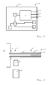
- FIG. 4 A prototype device for creating a jet of liquid has been built, and is illustrated schematically in Fig. 4 .
- a conduit 27 having essentially the same construction as the conduit 22 shown in Fig. 3 .
- a pulsed laser beam from a laser 28 was directed by a dichroic filter 29 through an objective 30 to a spot in the conduit 27.
- a strobed light-emitting diode 31 and camera 32 were used to capture images of the jet.
- the prototype device is representative for all the devices discussed above.
- the conduit 27 is made of glass, and has an outer diameter of 80 ⁇ m and an inner diameter of 50 ⁇ m. Its length is 20 mm.
- the laser 28 is a Nd:YAG laser providing light pulses with a wavelength of 532 nm and pulse duration of 6 ns.
- Fig. 5 is a diagram showing the maximum velocity of the thin and the thick jet against the energy in the laser pulse. It will be apparent that velocities of up to 640 m/s for the first stage of the jet were achieved. The second, thicker stage had maximum velocities in the region of 140 m/s.
- FIG. 6 A representative image of a jet is shown in Fig. 6 .
- the brightness of this image has been enhanced to allow for better reproduction and visibility, but the image has not otherwise been post-processed.
- One application is in the delivery of substances to at least part of a plant, i.e. to a plant or to plant material. For example, it would be possible to deliver a substance to a seed with little risk of creating a large hole in the seed coat or even destroying the seed.
- Another application is in puncturing part of an organism, e.g. an animal, plant or fungus.
- This can be biological material obtainable from a living animal, including a human being, or a plant seed, for example to induce germination.
- the devices outlined herein are in some embodiments suitable for puncturing part of a living animal, including a human being, e.g. to carry out an operation.
- a related application is in the delivery of DNA or RNA to plant or animal (including human) cells. Due to the small diameter of the thin jet 25, a small enough hole can be made in the cell membrane or cell wall that the cell is not destroyed. Of course, other compounds or compositions can be delivered to the cell, such as markers for imaging purposes.
- the jet can, for example, be directed onto a very small heat sink, but not the rest of the device, or only onto such components as are not at risk of being damaged by liquid jets.
- machining is used to denote all types of processing of workpieces in which the identity of the workpiece is changed by (locally) shaping the material thereof. For example, coatings can be removed locally, or an inscription can be made in the workpiece. Such inscriptions are useful for marking products for anti-counterfeiting purposes, for example.
- jets generated by the device disclosed herein is in the surface cleaning of workpieces. This can in particular include locally removing parts of a mask or other coating of a workpiece, e.g. in lithographic processes. Larger jets can be used to clean objects made of precious metals (e.g. jewellery) or of glass, for example, where it is desirable to remove as little of the material of the object to be cleaned as possible.
- the elements described herein can individually be essential to the invention in all its various forms or in any combination.
- a liquid herein, this includes mixtures and suspensions.
- the conduit section in which the meniscus is formed is approximately circle-cylindrical in the illustrated embodiments, it may taper or include a convergent-divergent nozzle, for example.
- a simple circle-cylindrical conduit is adequate.
- the liquid in the holder in which a vapour bubble is created need not be the same as that used to create the jet. Two immiscible liquids can be used, with an appropriately higher energy pulse being delivered.
Priority Applications (2)
| Application Number | Priority Date | Filing Date | Title |
|---|---|---|---|
| EP10163670A EP2388032A1 (de) | 2010-05-21 | 2010-05-21 | Vorrichtung zur Erzeugung eines mikrofluidischen Strahls und Verwendungen davon |
| PCT/EP2011/057499 WO2011144496A1 (en) | 2010-05-21 | 2011-05-10 | Device for creating a microfluidic jet and uses thereof |
Applications Claiming Priority (1)
| Application Number | Priority Date | Filing Date | Title |
|---|---|---|---|
| EP10163670A EP2388032A1 (de) | 2010-05-21 | 2010-05-21 | Vorrichtung zur Erzeugung eines mikrofluidischen Strahls und Verwendungen davon |
Publications (1)
| Publication Number | Publication Date |
|---|---|
| EP2388032A1 true EP2388032A1 (de) | 2011-11-23 |
Family
ID=42334045
Family Applications (1)
| Application Number | Title | Priority Date | Filing Date |
|---|---|---|---|
| EP10163670A Withdrawn EP2388032A1 (de) | 2010-05-21 | 2010-05-21 | Vorrichtung zur Erzeugung eines mikrofluidischen Strahls und Verwendungen davon |
Country Status (1)
| Country | Link |
|---|---|
| EP (1) | EP2388032A1 (de) |
Cited By (2)
| Publication number | Priority date | Publication date | Assignee | Title |
|---|---|---|---|---|
| NL2025071A (en) | 2019-03-08 | 2020-09-11 | Univ Twente | Jet injection system |
| CN114562233A (zh) * | 2022-03-11 | 2022-05-31 | 重庆大学 | 一种过热液体闪沸多孔喷射羽流相互作用的煤层气开采钻进方法 |
Citations (4)
| Publication number | Priority date | Publication date | Assignee | Title |
|---|---|---|---|---|
| EP0943666A2 (de) * | 1998-03-20 | 1999-09-22 | Canon Kabushiki Kaisha | Tinte, Inkjet, Tintenpatrone, Aufzeichnungseinheit, Aufzeichnungsgerät und Aufzeichnungsverfahren |
| EP1088862A1 (de) * | 1999-09-30 | 2001-04-04 | Canon Kabushiki Kaisha | Tintensatz für Farbtintenstrahl-Aufzeichnung und Aufzeichnungsverfahren, Aufzeichnungsgerät, Tintenpatrone, Aufzeichnungseinheit und Reduzierung von Farbvermischung mit diesem Tintensatz |
| DE10252105A1 (de) * | 2001-11-08 | 2003-05-28 | Benq Corp | Flüssigkeitsinjektionskopfstruktur und Herstellverfahren dafür |
| WO2004093818A2 (en) * | 2003-04-21 | 2004-11-04 | Stratagent Life Sciences | Apparatus and methods for repetitive microjet drug delivery |
-
2010
- 2010-05-21 EP EP10163670A patent/EP2388032A1/de not_active Withdrawn
Patent Citations (5)
| Publication number | Priority date | Publication date | Assignee | Title |
|---|---|---|---|---|
| EP0943666A2 (de) * | 1998-03-20 | 1999-09-22 | Canon Kabushiki Kaisha | Tinte, Inkjet, Tintenpatrone, Aufzeichnungseinheit, Aufzeichnungsgerät und Aufzeichnungsverfahren |
| EP1088862A1 (de) * | 1999-09-30 | 2001-04-04 | Canon Kabushiki Kaisha | Tintensatz für Farbtintenstrahl-Aufzeichnung und Aufzeichnungsverfahren, Aufzeichnungsgerät, Tintenpatrone, Aufzeichnungseinheit und Reduzierung von Farbvermischung mit diesem Tintensatz |
| DE10252105A1 (de) * | 2001-11-08 | 2003-05-28 | Benq Corp | Flüssigkeitsinjektionskopfstruktur und Herstellverfahren dafür |
| WO2004093818A2 (en) * | 2003-04-21 | 2004-11-04 | Stratagent Life Sciences | Apparatus and methods for repetitive microjet drug delivery |
| US20040260234A1 (en) | 2003-04-21 | 2004-12-23 | Ravi Srinivasan | Apparatus and methods for repetitive microjet durg delivery priority statement |
Non-Patent Citations (1)
| Title |
|---|
| ANTKOWIAK, A. ET AL.: "Short-term dynamics of a density interface following an impact", J. FLUID MECH., vol. 577, 2007, pages 241 - 250 |
Cited By (4)
| Publication number | Priority date | Publication date | Assignee | Title |
|---|---|---|---|---|
| NL2025071A (en) | 2019-03-08 | 2020-09-11 | Univ Twente | Jet injection system |
| WO2020182665A1 (en) | 2019-03-08 | 2020-09-17 | Universiteit Twente | Jet injection system |
| CN114562233A (zh) * | 2022-03-11 | 2022-05-31 | 重庆大学 | 一种过热液体闪沸多孔喷射羽流相互作用的煤层气开采钻进方法 |
| CN114562233B (zh) * | 2022-03-11 | 2023-12-12 | 重庆大学 | 一种过热液体闪沸多孔喷射羽流相互作用的煤层气开采钻进方法 |
Similar Documents
| Publication | Publication Date | Title |
|---|---|---|
| US6913605B2 (en) | Microfluidic devices and methods for producing pulsed microfluidic jets in a liquid environment | |
| JP5526345B2 (ja) | 気泡噴出部材及びその製造方法、気液噴出部材及びその製造方法、局所アブレーション装置及び局所アブレーション方法、インジェクション装置及びインジェクション方法 | |
| US20170028626A1 (en) | Compact Drop-on-Demand Apparatus Using Light Actuation Through Optical Fibers | |
| JP5948488B2 (ja) | 皮膚治療システム及び方法 | |
| Krizek et al. | Repetitive regime of highly focused liquid microjets for needle-free injection | |
| EP2388032A1 (de) | Vorrichtung zur Erzeugung eines mikrofluidischen Strahls und Verwendungen davon | |
| US11077251B2 (en) | Alignment of elongated particles in a particle delivery device | |
| WO2011144496A1 (en) | Device for creating a microfluidic jet and uses thereof | |
| EP2953668B1 (de) | Vorrichtung zu einspritzen einer arznei | |
| US20220153028A1 (en) | Jet injection system | |
| González-Sierra et al. | Bubble dynamics and speed of jets for needle-free injections produced by thermocavitation | |
| US20220218896A1 (en) | Apparatus and methods for medical applications of laser driven microfluid pumps | |
| US20230026586A1 (en) | System and Method for a Microfluidic Jet Generation from a Compact Device | |
| Plamadeala et al. | Three-dimensional photonic structures fabricated by two-photon polymerization for microfluidics and microneedles | |
| Ham et al. | A check valve controlled laser-induced microjet for uniform transdermal drug delivery | |
| US10039885B2 (en) | System and method for enhancing particle delivery to biological tissue | |
| 장헌재 | A Transdermal Drug Delivery System Based on Laser-generated Microjet | |
| WO2007003667A1 (es) | Procedimiento y dispositivo para impresión por micro-gotas de espuma | |
| Palanker et al. | Pulsed liquid microjet for microsurgical applications |
Legal Events
| Date | Code | Title | Description |
|---|---|---|---|
| AK | Designated contracting states |
Kind code of ref document: A1 Designated state(s): AL AT BE BG CH CY CZ DE DK EE ES FI FR GB GR HR HU IE IS IT LI LT LU LV MC MK MT NL NO PL PT RO SE SI SK SM TR |
|
| AX | Request for extension of the european patent |
Extension state: BA ME RS |
|
| PUAI | Public reference made under article 153(3) epc to a published international application that has entered the european phase |
Free format text: ORIGINAL CODE: 0009012 |
|
| STAA | Information on the status of an ep patent application or granted ep patent |
Free format text: STATUS: THE APPLICATION IS DEEMED TO BE WITHDRAWN |
|
| 18D | Application deemed to be withdrawn |
Effective date: 20120524 |