EP2387266A2 - Method for operating service unavailable mode of femto base station - Google Patents
Method for operating service unavailable mode of femto base station Download PDFInfo
- Publication number
- EP2387266A2 EP2387266A2 EP10729302A EP10729302A EP2387266A2 EP 2387266 A2 EP2387266 A2 EP 2387266A2 EP 10729302 A EP10729302 A EP 10729302A EP 10729302 A EP10729302 A EP 10729302A EP 2387266 A2 EP2387266 A2 EP 2387266A2
- Authority
- EP
- European Patent Office
- Prior art keywords
- oos
- fbs
- mode
- status
- oos mode
- Prior art date
- Legal status (The legal status is an assumption and is not a legal conclusion. Google has not performed a legal analysis and makes no representation as to the accuracy of the status listed.)
- Granted
Links
Images


Classifications
-
- H—ELECTRICITY
- H04—ELECTRIC COMMUNICATION TECHNIQUE
- H04W—WIRELESS COMMUNICATION NETWORKS
- H04W52/00—Power management, e.g. TPC [Transmission Power Control], power saving or power classes
- H04W52/02—Power saving arrangements
- H04W52/0203—Power saving arrangements in the radio access network or backbone network of wireless communication networks
- H04W52/0206—Power saving arrangements in the radio access network or backbone network of wireless communication networks in access points, e.g. base stations
-
- H—ELECTRICITY
- H04—ELECTRIC COMMUNICATION TECHNIQUE
- H04W—WIRELESS COMMUNICATION NETWORKS
- H04W48/00—Access restriction; Network selection; Access point selection
- H04W48/08—Access restriction or access information delivery, e.g. discovery data delivery
- H04W48/10—Access restriction or access information delivery, e.g. discovery data delivery using broadcasted information
-
- H—ELECTRICITY
- H04—ELECTRIC COMMUNICATION TECHNIQUE
- H04W—WIRELESS COMMUNICATION NETWORKS
- H04W16/00—Network planning, e.g. coverage or traffic planning tools; Network deployment, e.g. resource partitioning or cells structures
- H04W16/24—Cell structures
- H04W16/32—Hierarchical cell structures
-
- H—ELECTRICITY
- H04—ELECTRIC COMMUNICATION TECHNIQUE
- H04W—WIRELESS COMMUNICATION NETWORKS
- H04W36/00—Hand-off or reselection arrangements
- H04W36/04—Reselecting a cell layer in multi-layered cells
-
- H—ELECTRICITY
- H04—ELECTRIC COMMUNICATION TECHNIQUE
- H04W—WIRELESS COMMUNICATION NETWORKS
- H04W84/00—Network topologies
- H04W84/02—Hierarchically pre-organised networks, e.g. paging networks, cellular networks, WLAN [Wireless Local Area Network] or WLL [Wireless Local Loop]
- H04W84/04—Large scale networks; Deep hierarchical networks
- H04W84/042—Public Land Mobile systems, e.g. cellular systems
- H04W84/045—Public Land Mobile systems, e.g. cellular systems using private Base Stations, e.g. femto Base Stations, home Node B
-
- Y—GENERAL TAGGING OF NEW TECHNOLOGICAL DEVELOPMENTS; GENERAL TAGGING OF CROSS-SECTIONAL TECHNOLOGIES SPANNING OVER SEVERAL SECTIONS OF THE IPC; TECHNICAL SUBJECTS COVERED BY FORMER USPC CROSS-REFERENCE ART COLLECTIONS [XRACs] AND DIGESTS
- Y02—TECHNOLOGIES OR APPLICATIONS FOR MITIGATION OR ADAPTATION AGAINST CLIMATE CHANGE
- Y02D—CLIMATE CHANGE MITIGATION TECHNOLOGIES IN INFORMATION AND COMMUNICATION TECHNOLOGIES [ICT], I.E. INFORMATION AND COMMUNICATION TECHNOLOGIES AIMING AT THE REDUCTION OF THEIR OWN ENERGY USE
- Y02D30/00—Reducing energy consumption in communication networks
- Y02D30/70—Reducing energy consumption in communication networks in wireless communication networks
Definitions
- the present invention relates to a broadband wireless access system, and more particularly to a method for effectively operating an out of service (OOS) mode or a service unavailable mode of a femto base station (FBS).
- OOS out of service
- FBS femto base station
- a femtocell will hereinafter be described in brief.
- Femto is a prefix in the metric system, denoting a factor of 10 -15 or 0.000000000000001.
- a femtocell or FBS refers to an ultra-small indoor Access Point (AP) for low-power home use or office use.
- AP ultra-small indoor Access Point
- the femtocell is a small cellular base station (BS) connected to a broadband router and functions to connect 2 nd Generation (2G) and 3 rd Generation (3G) voice and data to a backbone network of a mobile communication service provider via the Digital Subscriber Line (DSL).
- 2G 2 nd Generation
- 3G 3 rd Generation
- the above-mentioned femtocell has the following advantages.
- IP Internet Protocol
- Femtocells can expand cell coverage and increase the quality of voice service. Mobile communication service providers are expecting that subscribers may be familiar with 3G by providing data service via femtocells.
- the femtocells are also called femto base stations (FBSs) or femto Base Transceiver Stations (femto BTSs).
- FBSs femto base stations
- femto BTSs femto Base Transceiver Stations
- femtocells offer the following benefits 1) to 4).
- One or more femtocells may be grouped on a service basis or geological area basis.
- a femtocell group that can access only a specific MS may be referred to as a Closed Subscriber Group (CSG).
- CSG Closed Subscriber Group
- a femtocell BS (FBS) recognizes a CSG ID of the MS so that it allows access of only the MS subscribed to the CSG.
- FIG. 1 illustrates an exemplary network configuration including FBSs.
- FBSs are new network entities added to a legacy network. Accordingly, the use of FBSs may bring about additions or modifications to an entire network structure.
- An FBS may directly access the Internet and function as a BS. Therefore, the FBS can perform almost all functions of a macro BS.
- the FBS may relay data from the macro BS to MSs.
- the network is configured by adding a Femto Network Gateway (FNG) to the legacy network.
- FNG Femto Network Gateway
- the FNG may communicate with an Access Service Network (ASN) gateway and a Connectivity Service Network (CSN).
- ASN Access Service Network
- CSN Connectivity Service Network
- the FNG may use an Rx interface for communicating with the ASN and an Ry interface for communicating with the CSN.
- An FBS may access directly a Transmission Control Protocol/Internet Protocol (TCP/IP) Internet and receive a service from the CSN via the FNG.
- An MS connected to the FBS may receive services from the FNG or CSN in relation to IP Multimedia Subsystem (IMS) authentication, etc.
- IMS IP Multimedia Subsystem
- the FBS is connected to a BS or AP via an R1 interface. This means that the FBS may receive a downlink channel from a macro BS. The FBS may also transmit a control signal to the macro BS.
- the above-mentioned FBS may be operated in an Out Of Service (OOS) mode (or a service unavailable mode) when a predetermined condition is satisfied.
- OOS Out Of Service
- the FBS is unable to provide a normal service during the OOS mode, such that there is needed an effective method that informs an MS of FBS status information before or after the FBS enters the OOS mode.
- An object of the present invention is to provide an effective communication system and a communication method thereof.
- Another object of the present invention is to provide a method for allowing an FBS to effectively inform a neighbor MS of an FBS OOS mode operation status.
- Another object of the present invention is to provide a method for enabling an FBS to effectively inform a neighbor part of an FBS OOS mode release such that a callback procedure is carried out.
- the present invention aims to provide a method for effectively transmitting and receiving control information in a wireless communication system using multiple carriers.
- a method for operating an out of service (OOS) mode of a femto base station (FBS) in a broadband wireless access system includes determining whether a predetermined OOS mode operation condition is satisfied, and broadcasting OOS mode information indicating an OOS mode status of the FBS according to satisfaction or non-satisfaction of the predetermined OOS mode operation condition.
- OOS out of service
- the OOS mode status may include a normal status, an OOS mode operation status in which an air interface service is not provided to a mobile station (MS), a callback status for informing the MS of the returning to the normal status, and an OOS mode initiation status indicating that the FBS enters the OOS mode after a lapse of a predetermined time.
- MS mobile station
- the OOS mode information may be contained in any one of a predetermined Medium Access Control (MAC) message, an OOS signal and interworking signal (IWS) broadcast through a predetermined broadcast channel.
- MAC Medium Access Control
- IWS interworking signal
- the OOS mode information may include at least one of a bit indicating the OOS mode status and a bit indicating a cause of an OOS mode entry
- the OOS signal may include at least one of OOS start time information in which the FBS enters the OOS mode, OOS duration information in which the FBS is operated in the OOS mode, a list of neighbor base stations (BSs), and a list of recommended BSs.
- the predetermined MAC message may be an Advanced Air Interface Self Organizing Network ADVertizement (AAI_SON-ADV) message, and the predetermined broadcast channel is a super frame header (SFH).
- AAI_SON-ADV Advanced Air Interface Self Organizing Network ADVertizement
- SCH super frame header
- an out of service (OOS) mode operating method for operating a mobile station (MS) in response to an OOS mode of a femto base station (FBS) in a broadband wireless access system includes receiving OOS mode information indicating OOS mode initiation of the FBS, and performing handover to a neighbor base station (BS) of the FBS.
- OOS out of service
- the OOS mode information may be contained in any one of a predetermined Medium Access Control (MAC) message, an OOS signal and interworking signal (IWS) broadcast through a predetermine broadcast channel.
- MAC Medium Access Control
- IWS interworking signal
- the OOS mode information may include at least one of a bit indicating the OOS mode status and a bit indicating a cause of an OOS mode entry
- the OOS signal may include at least one of OOS start time information in which the FBS enters the OOS mode, OOS duration information in which the FBS is operated in the OOS mode, a list of neighbor base stations (BSs), and a list of recommended BSs.
- the method may further include receiving OOS mode information indicating that the FBS returns to a normal status (i.e., a callback), and performing handover to the FBS.
- OOS mode information indicating that the FBS returns to a normal status (i.e., a callback)
- the OOS mode information indicating the callback of the FBS may be received through an interworking signal (IWS) broadcast from the FBS to a frequency domain of the neighbor BS.
- IWS interworking signal
- a mobile station in another aspect of the present invention, includes a processor, and a radio frequency (RF) module for transmitting and receiving an RF signal to and from an external part upon receiving a control signal from the processor.
- the processor receives out of service (OOS) mode information from a femto base station (FBS) by controlling the RF module, and determines whether to perform handover to the FBS, whether to re-enter a network of the FBS, or whether to perform handover from the FBS to a neighbor base station (BS) on the basis of the received OOS mode information.
- the OOS mode information is contained in any one of a predetermined Medium Access Control (MAC) message, an OOS signal and interworking signal (IWS) broadcast through a predetermined broadcast channel.
- the OOS mode information indicates an OOS mode status of the FBS according to satisfaction or non-satisfaction of a predetermined OOS mode operation condition.
- MAC Medium Access Control
- IWS interworking signal
- the OOS mode status may include a normal status, an OOS mode operation status in which an air interface service is not provided to an arbitrary MS, a callback status indicating returning to the normal status, and an OOS mode initiation status indicating that the FBS enters the OOS mode after a lapse of a predetermined time.
- the OOS mode information may include at least one of a bit indicating the OOS mode status and a bit indicating a cause of an OOS mode entry
- the OOS signal may include at least one of OOS start time information in which the FBS enters the OOS mode, OOS duration information in which the FBS is operated in the OOS mode, a list of neighbor base stations (BSs), and a list of recommended BSs.
- the predetermined MAC message may be an Advanced Air Interface Self Organizing Network ADVertizement (AAI_SON-ADV) message
- the predetermined broadcast channel may be a super frame header (SFH).
- the processor may perform handover to the neighbor BS. If the OOS mode status is the callback status or the normal status, the processor may perform either network re-entry for the FBS or handover to the FBS.
- the embodiments of the present invention can implement effective communication.
- MSs can recognize an OOS mode operation status of an FBS using a variety of methods, such that they may not perform unnecessary handover to a corresponding FBS and a specific MS that has already received a service may perform handover to a neighbor BS.
- an MS that leaves the FBS due to the OOS mode operation, can quickly perform network re-entry for the FBS through the callback method of the present invention.
- FIG. 1 is a conceptual diagram illustrating a conventional network structure including a femto network gateway (FNG).
- FNG femto network gateway
- FIG. 2 is a conceptual diagram illustrating an Inter-Working-Signal (IWS) resource allocation scheme applicable to embodiments of the present invention.
- IWS Inter-Working-Signal
- FIGS. 3(a) and 3(b) illustrate exemplary IWSs applicable to embodiments of the present invention.
- FIG. 4 illustrates an example of an Out Of Service (OOS) signal that can inform a mobile station (MS) of OOS mode information of a femto base station (FBS) according to an exemplary embodiment of the present invention.
- OOS Out Of Service
- FIG. 5 is a flowchart illustrating a method for enabling an MS to perform handover when an FBS enters an OOS mode according to an exemplary embodiment of the present invention.
- FIG. 6 is a flowchart illustrating a method for enabling an MS to re-perform handover to an FBS after an OOS mode of the FBS is ended.
- FIG. 7 is a flowchart illustrating an example of a callback operation using an interworking signal of an FBS according to an exemplary embodiment of the present invention.
- FIG. 8 is a flowchart illustrating another example of a callback operation using an interworking signal of an FBS according to an exemplary embodiment of the present invention.
- FIG. 9 is a block diagram of a transmitter and a receiver according to an exemplary embodiment of the present invention.
- the present invention relates to a wireless access system.
- the following exemplary embodiments of the present invention will disclose a variety of wireless access systems to which a femtocell is applied.
- the embodiments of the present invention disclose a method for effectively operating an OOS mode of a femto base station (FBS) and various methods for informing a mobile station (MS) of the operating method.
- FBS femto base station
- MS mobile station
- Exemplary embodiments described hereinbelow are combinations of elements and features of the present invention.
- the elements or features may be considered selective unless otherwise mentioned.
- Each element or feature may be practiced without being combined with other elements or features.
- an embodiment of the present invention may be constructed by combining parts of the elements and/or features. Operation orders described in the embodiments of the present invention may be rearranged. Some constructions or features of any one embodiment may be included in another embodiment and may be replaced with corresponding constructions or features of another embodiment.
- MS Mobile Station
- 'BS' refers to a terminal node of a network, which communicates directly with the MS.
- a specific operation described as performed by the BS may be performed by an upper node of the BS.
- a network comprised of a plurality of network nodes including a BS
- various operations performed for communication with an MS may be performed by the BS, or network nodes other than the BS.
- the term 'BS' may be replaced with the term 'fixed station', 'Node B', 'eNode B (eNB)', 'access point', 'Advanced Base Station (ABS), etc.
- the term 'MS' may be replaced with the term 'User Equipment (UE)', 'Subscriber Station (SS)', 'Mobile Subscriber Station (MSS)', 'mobile terminal', 'Advanced Mobile Station (AMS)', etc.
- UE User Equipment
- SS Subscriber Station
- MSS Mobile Subscriber Station
- AMS Advanced Mobile Station
- a transmitter means a node that transmits voice or data service and a receiver means a node that receives voice or data service.
- an MS may be a transmitter and a BS may be a receiver, on an uplink.
- the MS may be a receiver and the BS may be a transmitter, on a downlink.
- the MS may be any of a Personal Digital Assistant (PDA), a cellular phone, a Personal Communication Service (PCS) phone, a Global System for Mobile (GSM) phone, a Wideband Code Division Multiple Access (WCDMA) phone, a Mobile Broadband System (MBS) phone, etc.
- PDA Personal Digital Assistant
- PCS Personal Communication Service
- GSM Global System for Mobile
- WCDMA Wideband Code Division Multiple Access
- MBS Mobile Broadband System
- the MS may be any of a hand-held PC, a laptop computer, a smart phone, a MultiMode - MultiBand (MM-MB) terminal, etc.
- MM-MB MultiMode - MultiBand
- the smart phone refers to a terminal taking the advantages of a mobile terminal and a personal portable terminal. It integrates data communication functions of the personal portable terminal, inclusive of schedule management, fax transmission and reception, Internet connection, etc. into the mobile terminal.
- the MM-MB terminal is a terminal that has an in-built modem chip and is capable of operating in a portable Internet system and other communication systems (e.g. CDMA 2000, WCDMA, etc.).
- Exemplary embodiments of the present invention may be achieved by various means, for example, hardware, firmware, software, or a combination thereof.
- the methods according to exemplary embodiments of the present invention may be achieved by one or more Application Specific Integrated Circuits (ASICs), Digital Signal Processors (DSPs), Digital Signal Processing Devices (DSPDs), Programmable Logic Devices (PLDs), Field Programmable Gate Arrays (FPGAs), processors, controllers, microcontrollers, microprocessors, etc.
- ASICs Application Specific Integrated Circuits
- DSPs Digital Signal Processors
- DSPDs Digital Signal Processing Devices
- PLDs Programmable Logic Devices
- FPGAs Field Programmable Gate Arrays
- processors controllers, microcontrollers, microprocessors, etc.
- the methods according to the exemplary embodiments of the present invention may be implemented in the form of a module, a procedure, a function, etc. performing the above-described functions or operations.
- a software code may be stored in a memory unit and executed by a processor.
- the memory unit is located at the interior or exterior of the processor and may transmit and receive data to and from the processor via various known means.
- Exemplary embodiments of the present invention are supported by standard documents disclosed for at least one of wireless access systems including an Institute of Electrical and Electronics Engineers (IEEE) 802 system, a 3 rd Generation Project Partnership (3GPP) system, a 3GPP Long Term Evolution (LTE) system, and a 3GPP2 system.
- IEEE Institute of Electrical and Electronics Engineers
- 3GPP 3 rd Generation Project Partnership
- LTE 3GPP Long Term Evolution
- 3GPP2 3 rd Generation Project 2
- All terminologies used herein may be supported by at least one of P802.16-2004, P802.16e-2005, and P802.16Rev2 documents which are the standards of IEEE 802.16.
- a femtocell can construct an independent network having a relatively small cell radius, differently from a conventional cell. If it is assumed that a cell having a large cell radius is called a macro cell, the femtocell is connected to a general macro cell through a backbone connection and can communicate with the general macro cell using its own network capacity.
- One macro cell may include a plurality af femtocells. Differently from the general macro cell, the femtocell can be switched on or off. In order to reduce power consumption, the femtocell can be operated in a sleep mode or a low duty mode (LDM). In addition, the femtocell is unable to directly connect to other femto cells, such that it can be distinguished from a relay station.
- LDM low duty mode
- the femtocell establishes synchronization with a macro cell to which the femtocell belongs.
- the femtocell may transmit an Inter-Working-Signal (IWS) in a frequency domain of the macro cell.
- IWS Inter-Working-Signal
- Femto base stations (FBSs) using the same frequency domain may transmit the IWS using the same resources, and other FBSs using different frequency domains may transmit the IWS using different resources.
- a mobile station (MS) detects the IWS transferred from the FBSs, such that it searches for a specific frequency domain without additionally scanning different frequency domains, and thus detects femtocells that transmit the IWS through a corresponding frequency domain.
- FBSs belonging to an arbitrary macro BS use frequency domains different from that of the macro BS, and may broadcast the IWS to a frequency domain of a macro BS so as to inform an MS of the presence of such FBSs.
- the MS scans the frequency domain of the macro BS, such that it is impossible for the MS to recognize the presence of FBSs operating in other frequency domains so long as the MS separately scans other frequency domains. Therefore, the MS detects the IWS broadcast to a frequency domain of the macro BS, such that it can detect an FBS without additionally scanning a frequency domain of the FBS.
- the IWS may be included in a super frame header (SFH), or may be broadcast through a separate MAC message. In addition, the IWS may be broadcast at intervals of an SFH-basis unit.
- SFH super frame header
- the IWS may be broadcast at intervals of an SFH-basis unit.
- the IWS may have coverage similar to that of the SFH, and a resource allocation scheme thereof is shown in FIG. 2 .
- FIG. 2 is a conceptual diagram illustrating an IWS resource allocation scheme applicable to embodiments of the present invention.
- an MS can simultaneously search for femtocells of two frequency domains through a frequency division multiplexing (FDM) - based preamble signal.
- FDM frequency division multiplexing
- a total of 288 data tons may be used.
- the system bandwidth is extended from 5MHz to 10MHz and 20MHz, the number of frequency domains requisite for IWS transmission and the number of associated data tons may be linearly increased.
- the IWS format will be described with reference to FIG. 3 .
- FIGS. 3(a) and 3(b) illustrate exemplary IWSs applicable to embodiments of the present invention.
- FIG. 3(a) shows an exemplary IWS provided when second layer (L2) information is required such that an MS starts handover to a femto BS or awakes a sleeping femto BS.
- the IWS may include P-bit preamble information, an on/off indicator capable of indicating whether the femto BS is turned on or off using only one bit, and 8-bit cyclic redundancy check (CRC) information.
- specific information indicating whether the femto BS is turned on or off may indicate whether the femto BS is to be turned on or off after the lapse of a predetermined time.
- FIG. 3(b) illustrates another exemplary IWS provided when second layer (L2) information is required such that an MS starts handover to a femto BS or awakes a sleeping femto BS.
- the IWS may include N-bit FBS identifier (ID), an on/off indicator, and CRC information.
- SCH synchronous channel
- the SCH may have two usages, i.e., the SCH may be used to achieve physical synchronization, and may also be used to recognize segment information and a base station (BS) ID.
- two usages may be implemented as a preamble having the size of one symbol.
- the SCH is classified into a primary SCH (PSCH) for physical synchronous and a secondary SCH (SSCH) for segment information and a BS ID.
- PSCH primary SCH
- SSCH secondary SCH
- N orthogonal sequences for each segment are used, such that a BS ID and the like can be identified according to a code division multiplexing (CDM) scheme.
- CDM code division multiplexing
- the term 'segment' may represent three sector IDs when three sectors are used.
- OOS Out Of Service
- the OOS mode may indicate a specific status in which a specific condition is satisfied such that a normal service is not provided to an MS.
- the OOS mode may indicate a disable downlink air interface transmitter status.
- the FBS may enter an OOS mode when at least one of the following conditions 1) to 4) is satisfied.
- Planned FBS Shutdown Under the condition that an FBS shutdown time is pre-recognized according to a predetermined schedule or how many hours are needed for FBS shutdown, the FBS enters an OOS mode at a predetermined time. For example, an example of such planned FBS shutdown may be rebooting of an FBS.
- Unexpected Power-Off Due to an unexpected cause, for example, a power failure, an FBS may be powered off, such that it may enter an OOS mode.
- an FBS may enter an OOS mode. However, before an FBS enters the OOS mode, the FBS should pre-inform an MS, that is receiving a service from the FBS, of the entrance into an OOS mode. A method for allowing the FBS to inform the MS of the entry into the OOS mode will hereinafter be described with reference to FIG. 4 .
- 'OOS mode information' For convenience of description and better understanding of the present invention, specific information indicating the entry into the OOS mode of the FBS, an entry time, a duration, and the like is hereinafter referred to as 'OOS mode information', and a signal needed for transmitting the OOS mode information to an MS is hereinafter referred to as an 'OOS signal'.
- FIG. 4 illustrates an example of an OOS signal that can inform an MS of OOS mode information of an FBS according to an exemplary embodiment of the present invention.
- the OOS signal may further include OOS mode information in the above-mentioned IWS.
- the OOS mode information may be comprised of a plurality of bits. If the OOS mode information indicates that an FBS enters an OOS mode, the OOS signal may further include OOS start time information and OOS duration information. In addition, the OOS signal may further include information of a recommended BS so as to support handover of a corresponding MS because the MS belonging to a femtocell cannot receive a necessary service from the FBS any longer.
- the following embodiments of the present invention propose two kinds of OOS mode information 1) and 2).
- First OOS mode information may be comprised of 5 bits (bit #1 ⁇ bit #5) except for OOS start time information and OOS duration information.
- Bit #1 is used as an OOS indicator. If the bit #1 is set to 1, this means that a current mode is an OOS mode. Alternatively, if the bit #1 is set to zero '0', this means that a current status is a normal status.
- Bit #2 is used to indicate a backbone network data link status. If the bit #2 is set to 1, this means that data communication is made unavailable because of a faulty operation in a backbone link. Alternatively, if the bit #2 is set to zero '0', this means a normal status.
- Bit #3 is used to indicate a backbone network control link status. If the bit #3 is set to 1, this means that a faulty operation occurs in network entities that include an overlay macro BS and control an FBS such that communication is made unavailable. Alternatively, if the bit #3 is set to zero '0', this means a normal status.
- Bit #2 or Bit #3 may be used to indicate a backbone network link status.
- the added result of Bit #2 and Bit #3 may indicate a control/data link status using only one bit.
- Bit #4 is used to indicate shutdown of main power. If Bit #4 is set to 1, this means that a faulty operation or failure occurs in main power such that an FBS is operated by auxiliary power (e.g., battery). Alternatively, if the bit #4 is set to zero '0', this means a normal status such that no faulty operations occur in FBS power.
- Bit #5 is used to indicate a warning status of FBS power shutdown. If Bit #5 is set to 1, this means that main/auxiliary power is immediately shut down or an FBS is powered off according to a predetermined management schedule. Otherwise, if Bit #5 is set to zero '0', this means a normal status.
- Second OOS mode information may be comprised of 4 bits (Bit #1 ⁇ Bit #4) except for OOS start time information and OOS duration information.
- Bit #1 and Bit #2 may indicate an FBS OOS status type (or OOS type) or an FBS action type.
- Bit #1 and Bit #2 are set to 0x00, this means that a current FBS is in a normal status.
- Bit #1 and Bit #2 are set to 0x01, this means that a current FBS is in progress of a callback procedure returning to a normal status.
- Bit #1 and Bit #2 are set to 0x10, this means that a current FBS is in progress of an OOS mode.
- Bit #1 or Bit #2 of 0x10 means that a current FBS is in an active status of the OOS mode.
- Bit #1 or Bit #2 of 0x10 can be transmitted under an FBS operable status. In other words, Bit #1 or Bit #2 of 0x10 may indicate that a necessary service cannot be provided to an MS even though an air interface of an FBS is activated.
- Bit #1 and Bit #2 are set to 0x11, this means that a current FBS is going to enter an OOS mode.
- Bit #3 or Bit #4 may indicate an OOS reason type.
- Bit #3 and Bit #4 are set to 0x00, this means that data communication is made unavailable due to a faulty operation of a backbone link.
- Bit #3 and Bit #4 are set to 0x01, this means that a faulty operation occurs in network entities that include an overlay macro BS and control an FBS such that it is impossible to achieve communication among such network entities.
- Bit #3 and Bit #4 are set to 0x10, this means the shutdown of main power such that an FBS is operated by battery power serving as auxiliary power due to a faulty operation of main power.
- an FBS may include the OOS signal or the OOS mode information in a predetermined broadcast channel signal (e.g., super frame header (SFH)), and then broadcast the resultant broadcast channel signal at intervals of a predetermined time (e.g., at every SFH).
- a predetermined broadcast channel signal e.g., super frame header (SFH)
- SFH super frame header
- an FBS may also broadcast the OOS signal or the OOS mode information through a predetermined MAC message.
- a predetermined MAC message As an example of such an MAC message, an Advanced Air Interface Self Organizing Network ADVertizement (AAI_SON-ADV) message may be used.
- FIG. 5 is a flowchart illustrating a method for enabling an MS to perform handover when an FBS enters an OOS mode according to an exemplary embodiment of the present invention.
- k 4
- an FBS may broadcast an OOS signal including OOS mode information to an MS such that an OOS mode-associated status of the FBS can be periodically provided to the MS. If the FBS is operated in a normal mode, each bit (e.g., Bit #1 and Bit #2) indicating an OOS type is set to 0x00, such that the OOS signal may be broadcast to the MS at step S501.
- each bit e.g., Bit #1 and Bit #2
- the MS may exchange data with the FBS at step S502.
- the FBS may broadcast an OOS signal to the MS on a superframe basis, and may normally communicate with the MS at steps S503 and S504.
- the FBS may start or initiate the OOS mode if any one of the above-mentioned OOS mode entry conditions is satisfied.
- the FBS may set a specific bit indicating the OOS type to a specific value (e.g., 0x11) indicating the beginning of the OOS mode, and may broadcast the OOS signal to the MS at step S505.
- the OOS signal may include OOS start time information and OOS duration information.
- the FBS may start operation in an OOS mode at the OOS start time
- the OOS duration may be duration of an OOS mode.
- the MS receives the OOS signal such that it can recognize that the FBS is to be operated in an OOS mode during the OOS duration starting from the OOS start time.
- the MS cannot continuously receive a service from the FBS, such that a handover from the MS to the macro BS is decided, and a handover request message is transmitted to the FBS at step S506.
- the embodiments of the present invention assume the handover to the macro BS, the scope or spirit of the present invention is not limited thereto, and the MS can be handed over to any of femtocell's neighbor BSs capable of providing a service to a corresponding MS. If a list of neighbor BSs or a list of recommended BSs is contained in the OOS signal, the MS may decide a handover-target BS by referring to the lists.
- the FBS having received a handover request message from the MS may transfer the handover request message to the macro BS at step S507.
- the macro BS may transfer a handover response message to the FBS at step S508.
- the FBS having received the handover response message may transfer a handover command message to the MS.
- the handover command message may transmit a dedicated callback CDMA code to the MS, such that the MS can easily re-enter the femtocell when the FBS is normally re-operated.
- the dedicated callback code will be described in detail.
- FIG. 5 shows that an advanced mobile station (AMS) initiates handover (HO), it should be noted that the FBS may initiate handover (HO).
- the FBS may periodically broadcast an OOS signal to the MS until a current time reaches a specific time indicated by OOS start time information at step S510.
- each broadcast OOS signal may include OOS start time information and OOS duration information.
- the MS may transmit a ranging request message to the macro BS so as to perform handover (HO) to the macro BS at step S511.
- the MS may also transmit a handover indication message to the FBS (not shown).
- the FBS may be operated in an OOS mode.
- the problem e.g., a backbone network link problem
- an air interface of the FBS can be normally operated.
- the FBS sets a bit indicating an OOS type to a value (e.g., 0x10) indicating that the FBS is operated in the OOS mode, such that the FBS can broadcast the OOS signal to the MS at step S512.
- a callback operation of the FBS will hereinafter be described with reference to FIG. 6 .
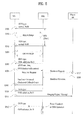
- FIG. 6 is a flowchart illustrating a method for enabling an MS to re-perform handover to an FBS after an OOS mode of the FBS is ended.
- FIG. 6 For convenience of description and better understanding of the present invention, it is assumed that the situation of FIG. 6 is continued from FIG. 5 .
- the FBS can be operated in the OOS mode in the range from a first time indicated by the OOS start time information to a second time indicated by the OOS duration information.
- the FBS sets a bit indicating an OOS type to a specific value (e.g., 0x10) indicating that the FBS is operated in the OOS mode in such a manner that the FBS can periodically inform the MS that the FBS is operated in the OOS mode, such that it can broadcast the OOS signal at steps S601 and S602.
- the FBS sets a bit indicating an OOS type to a specific value (e.g., 0x01) indicating an OOS mode callback, such that it can broadcast the OOS signal to the MS at step S603.
- a specific value e.g., 0x01
- the MS may scan a frequency domain of a corresponding FBS, such that it can determine whether to receive again the service from the FBS after the lapse of a predetermined time (e.g., the predetermined time ranges from a time point indicated by the OOS start time information to the other time point (i.e., a callback time) indicated by the OOS duration time information).
- a predetermined time e.g., the predetermined time ranges from a time point indicated by the OOS start time information to the other time point (i.e., a callback time) indicated by the OOS duration time information.
- the MS may decide handover to the FBS, and may transmit a handover request message to the macro BS at step S604.
- the macro BS may transmit a handover response message to the MS at step S605.
- the FBS sets the bit indicating the OOS type to a specific value (e.g., 0x00) indicating the normal status, such that it can broadcast the OOS signal at step S606.
- a specific value e.g., 0x00
- the MS may transmit a ranging request message to the FBS at step S607.
- the MS upon receiving the dedicated callback code in the same manner as in the step S509 of FIG. 5 , the MS transmits a dedicated callback code instead of the ranging request message so as to simplify a handover procedure.
- the FBS may transmit a ranging response message to the MS at step S608.
- the FBS Since the FBS is operated in the normal mode, it can periodically broadcast the OOS signal shown in step S606 (step S609).
- the MS and the FBS can normally communicate with each other after completing the handover procedure.
- the FBS may announce the OOS mode status to neighbor parts by adding the OOS mode information to the IWS.
- this announcement can be effectively used for two purposes.
- the FBS can inform MSs, that are located in the vicinity of the FBS at a callback time although they are not connected to the FBS when the FBS enters the OOS mode, of the FBS redriving through the IWS.
- a second purpose is as follows.
- the FBS that is operated in the OOS mode informs neighbor MSs of the FBS OOS mode operation status through the IWS, such that it can prevent the MSs from being unnecessarily handed over to a corresponding FBS.
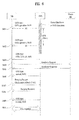
- FIG. 7 is a flowchart illustrating an example of a callback operation using an IWS of an FBS according to an exemplary embodiment of the present invention.
- FIG. 7 For convenience of description and better understanding of the present invention, it is assumed that the situation of FIG. 7 is also continued from FIG. 5 in a similar way to FIG. 6 .
- the FBS can be operated in the OOS mode in the range from a first time indicated by the OOS start time information to a second time indicated by the OOS duration information.
- the FBS sets a bit indicating an OOS type to a specific value (e.g., 0x10) indicating that the FBS is operated in the OOS mode in such a manner that the FBS can periodically inform the MS that the FBS is operated in the OOS mode, such that it can broadcast the OOS signal at steps S701 and S702.
- the FBS sets a bit indicating an OOS type to a specific value (e.g., 0x01) indicating an OOS mode callback, such that it can broadcast the IWS to a frequency domain of the macro BS at step S703.
- a specific value e.g., 0x01
- the MS receives the IWS from the FBS without additionally scanning the frequency domain of the FBS, such that it can recognize a current status of the FBS through the IWS.
- Steps S704 to S710 of FIG. 7 are similar to steps S604 to S610 of FIG. 6 , and as such detailed description thereof will herein be omitted for convenience of description.
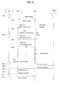
- FIG. 8 is a flowchart illustrating another example of a callback operation using an IWS of an FBS according to an exemplary embodiment of the present invention.
- a first MS receives a service from an FBS and a second MS (MS 2) receives a service from a macro BS at steps S801 and S802.
- the FBS sets a bit indicating an OOS type to a specific value indicating OOS initiation, such that it can broadcast the OOS signal at step S803.
- the OOS signal may include OOS start time and OOS duration information.
- the FBS informs each MS, that is located in the vicinity of the FBS whereas it does not receive the service from the FBS, of FBS status information (i.e., the OOS mode initiation), it can prevent the occurrence of unnecessary handover.
- the FBS may include the OOS mode information in the IWS, and broadcast the resultant IWS to the frequency domain of the macro BS at step S804.
- the IWS may further include OOS start time information and OOS duration information. Therefore, MS 2 receives an IWS such that it recognizes that the FBS enters the OOS mode and does not attempt to perform unnecessary handover to the FBS.
- the FBS may broadcast the OOS signal at intervals of a predetermined time (e.g., at every SFH), such that it can inform the MS that the FBS is going to perform the OOS mode initiation at step S805.
- a predetermined time e.g., at every SFH
- the FBS may be operated in the OOS mode.
- the problem e.g., a backbone network link problem
- an air interface of the FBS can be normally operated.
- the FBS sets a bit indicating an OOS type to a specific value (e.g., 0x10) indicating that the FBS is operated in the OOS mode, such that the FBS can broadcast the OOS signal to the MS at step S806.
- the FBS sets a bit indicating the OOS type to a specific value (e.g., 0x01) indicating a callback operation, and broadcasts the bit to a frequency domain of the macro BS through the IWS at step S807.
- a specific value e.g., 0x01
- MS 2 that receives a service from the macro BS, can recognize that the FBS is re-operated in the OOS mode, and can transmit a handover request message to the macro BS so as to perform handover to the FBS at step S808.
- the macro BS may transmit a handover response message to the MS at step S809.
- MS 2 may transmit a ranging request message to the FBS at step S810, and the FBS may transmit a ranging response message to the ranging request message to the MS 2 at step S811.
- the MS 2 and the FBS can normally communicate with each other after completing the handover procedure at step S812.
- the MS operates as a transmitter on an uplink and as a receiver on a downlink
- the BS operates as a receiver on the uplink and as a transmitter on the downlink. Therefore, each of the MS and the BS may have a transmitter and a receiver for transmitting and receiving information or data.
- Each of the transmitter and the receiver may include a processor, modules, parts and/or means for performing the exemplary embodiments of the present invention.
- the transmitter and the receiver may include modules (or means) for encrypting messages, modules for interpreting encrypted messages, and antennas for transmitting and receiving messages.
- An example of the transmitter and the receiver will be described with reference to FIG. 9 .
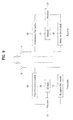
- FIG. 9 is a block diagram of a transmitter and a receiver according to an exemplary embodiment of the present invention.
- Each of the receiver and the transmitter may include an antenna 5 or 10, a processor 20 or 30, a Transmission (Tx) module 40 or 50, a Reception (Rx) module 60 or 70, and a memory 80 or 90.
- Tx Transmission
- Rx Reception
- Each component of the transmitter operates in correspondence with its counterpart of the receiver.
- the antennas 5 and 10 transmit Radio Frequency (RF) signals generated from the Tx modules 40 and 50 in the air interface, or receive RF signals in the air interface and output the received RF signals to the Rx modules 60 and 70.
- RF Radio Frequency
- MIMO Multiple Input Multiple Output
- two or more antennas may be used.
- An antenna, a Tx module and an Rx module may collectively form an RF module.
- the processors 20 and 30 provide overall control to the MS.
- the processors 20 and 30 may perform a control function, a MAC frame conversion control function based on service characteristics and propagation environments, a handover function, authentication, and encryption in order to perform the afore-described exemplary embodiments.
- a processor of the MS controls the RF module, receives an IWS or a predetermined MAC message (e.g., an AAI_SON-ADV message) from the FBS, or receives an OOS signal that is transmitted at intervals of a predetermined time over a predetermined broadcast channel (e.g., SFH), such that it can obtain OOS mode information contained in the received signal.
- a predetermined MAC message e.g., an AAI_SON-ADV message
- SFH predetermined broadcast channel
- the processor can recognize an OOS mode status (i.e., an OOS type) of an FBS, an OOS duration of the FBS, a reason why the FBS enters the OOS mode, and the like. Therefore, the process can decide whether to perform handover to a corresponding FBS, whether to perform network re-entry for the FBS, or whether to perform handover to a macro BS.
- OOS mode status i.e., an OOS type
- the process can decide whether to perform handover to a corresponding FBS, whether to perform network re-entry for the FBS, or whether to perform handover to a macro BS.
- the processor of the FBS can determine whether an OOS mode entry condition is satisfied, such that it sets a bit of appropriate OOS mode information and broadcasts the bit to one or more neighbor BSs using the above-mentioned method. In addition, the processor of the FBS determines that the FBS enters the OOS mode, such that it sets a cell-bar bit of the SFH to '1' so as to prevent an unnecessary access attempt of the MS.
- the processor of the BS interprets the MAC message or data transmitted from the MS, such that it performs allocation of uplink resources required for the MS.
- the processor generates an uplink grant for informing the MS of allocation content, such that it may perform scheduling to transmit the uplink grant.
- the Tx modules 40 and 50 may transmit data scheduled by the processors 20 and 30 to the antennas 5 and 10, after a predetermined coding and modulation.
- the Rx modules 60 and 70 may recover original data by decoding and demodulating RF signals received through the antennas 5 and 10 over the air interface and output the original data to the processors.
- the memories 80 and 90 may store programs for processing and control operations of the processors 20 and 30 and temporarily store input/output data (e.g. scanning results or a neighbor list). Also, the memories 80 and 90 may include at least one of a flash memory-type storage medium, a hard disc-type storage medium, a multimedia card micro-type storage medium, a card-type memory (e.g. a Secure Digital (SD) or extreme Digital (XS) memory), a Random Access Memory (RAM), a Read-Only Memory (ROM), an Electrically Erasable Programmable Read-Only Memory (EEPROM), a Programmable Read-Only Memory (PROM), a magnetic memory, a magnetic disc, and optical disk.
- SD Secure Digital
- XS extreme Digital
- RAM Random Access Memory
- ROM Read-Only Memory
- EEPROM Electrically Erasable Programmable Read-Only Memory
- PROM Programmable Read-Only Memory
- the BS may perform, in at least one of the above-described modules or in a separately procured means, module or part, a control function according to the embodiments of the present invention, an Orthogonal Frequency Division Multiple Access (OFDMA) packet scheduling, Time Division Duplex (TDD) packet scheduling, channel multiplexing, a variable MAC frame control function based on service characteristics and a propagation environment, a real-time high-speed traffic control function, a handover function, an authentication and encryption function, a packet modulation and demodulation function for data transmission and reception, a high-speed packet channel coding function, and a real-time modem control function.
- OFDMA Orthogonal Frequency Division Multiple Access
- TDD Time Division Duplex
- the embodiments of the present invention can provide a method for effectively informing an MS of an FBS OOS mode operation and an FBS OOS status in a broadband wireless access system including a femtocell, and an MS for the same.
- a broadband wireless access system including a femtocell
- an MS for the same.
- the method and the MS of the embodiments of the present invention have been disclosed on the basis of only an IEEE 802.16m system application, it should be noted that the embodiments are also applicable not only to an IEEE 802.xx system but also to other wireless mobile communication systems each having a femto BS (FBS).
- FBS femto BS
Landscapes
- Engineering & Computer Science (AREA)
- Computer Networks & Wireless Communication (AREA)
- Signal Processing (AREA)
- Computer Security & Cryptography (AREA)
- Mobile Radio Communication Systems (AREA)
Abstract
Description
- The present invention relates to a broadband wireless access system, and more particularly to a method for effectively operating an out of service (OOS) mode or a service unavailable mode of a femto base station (FBS).
- A femtocell will hereinafter be described in brief.
- Femto is a prefix in the metric system, denoting a factor of 10-15 or 0.000000000000001. Hence a femtocell or FBS refers to an ultra-small indoor Access Point (AP) for low-power home use or office use. Although the term "femtocell" is sometimes interchangeably used with "picocell", the former is used in the sense of a more advanced cell. The femtocell is a small cellular base station (BS) connected to a broadband router and functions to connect 2nd Generation (2G) and 3rd Generation (3G) voice and data to a backbone network of a mobile communication service provider via the Digital Subscriber Line (DSL).
- The above-mentioned femtocell has the following advantages.
- Recently, a new research paper has proposed a method for the femtocell to expedite the spread of 3G technology and greatly increase indoor coverage. Up to 2012, it is expected that the number of the femtocell BS users throughout the world will increase to about one hundred and two million, and the number of access points (APs) serving as BSs will also increase to about thirty-two million. According to chief analyst of ABI Research, Stuart Carlaw, "From a technological standpoint, their better in-building coverage for technologies such as WCDMA, HSDPA and EVDO is an incredibly important aspect of service delivery. From a strategic and financial standpoint, the routing of traffic through the Internet Protocol (IP) network significantly enhances network quality and capacity, and reduces the OPEX that carriers expend on backhaul."
- Femtocells can expand cell coverage and increase the quality of voice service. Mobile communication service providers are expecting that subscribers may be familiar with 3G by providing data service via femtocells. The femtocells are also called femto base stations (FBSs) or femto Base Transceiver Stations (femto BTSs).
- In summary, femtocells offer the following benefits 1) to 4).
- 1) Cell coverage improvement
- 2) Infrastructure cost decrease
- 3) New service offering
- 4) Fixed Mobile Convergence (FMC) acceleration.
- One or more femtocells may be grouped on a service basis or geological area basis. For example, a femtocell group that can access only a specific MS may be referred to as a Closed Subscriber Group (CSG). A femtocell BS (FBS) recognizes a CSG ID of the MS so that it allows access of only the MS subscribed to the CSG.
-
FIG. 1 illustrates an exemplary network configuration including FBSs. - FBSs are new network entities added to a legacy network. Accordingly, the use of FBSs may bring about additions or modifications to an entire network structure. An FBS may directly access the Internet and function as a BS. Therefore, the FBS can perform almost all functions of a macro BS. In addition, the FBS may relay data from the macro BS to MSs.
- In
FIG. 1 , the network is configured by adding a Femto Network Gateway (FNG) to the legacy network. - Referring to
FIG. 1 , the FNG may communicate with an Access Service Network (ASN) gateway and a Connectivity Service Network (CSN). The FNG may use an Rx interface for communicating with the ASN and an Ry interface for communicating with the CSN. - An FBS may access directly a Transmission Control Protocol/Internet Protocol (TCP/IP) Internet and receive a service from the CSN via the FNG. An MS connected to the FBS may receive services from the FNG or CSN in relation to IP Multimedia Subsystem (IMS) authentication, etc.
- The FBS is connected to a BS or AP via an R1 interface. This means that the FBS may receive a downlink channel from a macro BS. The FBS may also transmit a control signal to the macro BS.
- The above-mentioned FBS may be operated in an Out Of Service (OOS) mode (or a service unavailable mode) when a predetermined condition is satisfied. The FBS is unable to provide a normal service during the OOS mode, such that there is needed an effective method that informs an MS of FBS status information before or after the FBS enters the OOS mode.
- An object of the present invention is to provide an effective communication system and a communication method thereof.
- Another object of the present invention is to provide a method for allowing an FBS to effectively inform a neighbor MS of an FBS OOS mode operation status.
- Another object of the present invention is to provide a method for enabling an FBS to effectively inform a neighbor part of an FBS OOS mode release such that a callback procedure is carried out.
- Additional advantages, objects, and features of the invention will be set forth in part in the description which follows and in part will become apparent to those having ordinary skill in the art upon examination of the following or may be learned from practice of the invention. The objectives and other advantages of the invention may be realized and attained by the structure particularly pointed out in the written description and claims hereof as well as the appended drawings.
- In order to solve the above-mentioned technical subjects, the present invention aims to provide a method for effectively transmitting and receiving control information in a wireless communication system using multiple carriers.
- To achieve these objects and other advantages and in accordance with the purpose of the invention, as embodied and broadly described herein, a method for operating an out of service (OOS) mode of a femto base station (FBS) in a broadband wireless access system includes determining whether a predetermined OOS mode operation condition is satisfied, and broadcasting OOS mode information indicating an OOS mode status of the FBS according to satisfaction or non-satisfaction of the predetermined OOS mode operation condition.
- The OOS mode status may include a normal status, an OOS mode operation status in which an air interface service is not provided to a mobile station (MS), a callback status for informing the MS of the returning to the normal status, and an OOS mode initiation status indicating that the FBS enters the OOS mode after a lapse of a predetermined time.
- The OOS mode information may be contained in any one of a predetermined Medium Access Control (MAC) message, an OOS signal and interworking signal (IWS) broadcast through a predetermined broadcast channel.
- The OOS mode information may include at least one of a bit indicating the OOS mode status and a bit indicating a cause of an OOS mode entry, and the OOS signal may include at least one of OOS start time information in which the FBS enters the OOS mode, OOS duration information in which the FBS is operated in the OOS mode, a list of neighbor base stations (BSs), and a list of recommended BSs.
- The predetermined MAC message may be an Advanced Air Interface Self Organizing Network ADVertizement (AAI_SON-ADV) message, and the predetermined broadcast channel is a super frame header (SFH).
- In another aspect of the present invention, an out of service (OOS) mode operating method for operating a mobile station (MS) in response to an OOS mode of a femto base station (FBS) in a broadband wireless access system includes receiving OOS mode information indicating OOS mode initiation of the FBS, and performing handover to a neighbor base station (BS) of the FBS.
- The OOS mode information may be contained in any one of a predetermined Medium Access Control (MAC) message, an OOS signal and interworking signal (IWS) broadcast through a predetermine broadcast channel.
- The OOS mode information may include at least one of a bit indicating the OOS mode status and a bit indicating a cause of an OOS mode entry, and the OOS signal may include at least one of OOS start time information in which the FBS enters the OOS mode, OOS duration information in which the FBS is operated in the OOS mode, a list of neighbor base stations (BSs), and a list of recommended BSs.
- The method may further include receiving OOS mode information indicating that the FBS returns to a normal status (i.e., a callback), and performing handover to the FBS.
- The OOS mode information indicating the callback of the FBS may be received through an interworking signal (IWS) broadcast from the FBS to a frequency domain of the neighbor BS.
- In another aspect of the present invention, a mobile station (MS) includes a processor, and a radio frequency (RF) module for transmitting and receiving an RF signal to and from an external part upon receiving a control signal from the processor. The processor receives out of service (OOS) mode information from a femto base station (FBS) by controlling the RF module, and determines whether to perform handover to the FBS, whether to re-enter a network of the FBS, or whether to perform handover from the FBS to a neighbor base station (BS) on the basis of the received OOS mode information. The OOS mode information is contained in any one of a predetermined Medium Access Control (MAC) message, an OOS signal and interworking signal (IWS) broadcast through a predetermined broadcast channel. The OOS mode information indicates an OOS mode status of the FBS according to satisfaction or non-satisfaction of a predetermined OOS mode operation condition.
- The OOS mode status may include a normal status, an OOS mode operation status in which an air interface service is not provided to an arbitrary MS, a callback status indicating returning to the normal status, and an OOS mode initiation status indicating that the FBS enters the OOS mode after a lapse of a predetermined time.
- The OOS mode information may include at least one of a bit indicating the OOS mode status and a bit indicating a cause of an OOS mode entry, and the OOS signal may include at least one of OOS start time information in which the FBS enters the OOS mode, OOS duration information in which the FBS is operated in the OOS mode, a list of neighbor base stations (BSs), and a list of recommended BSs.
- The predetermined MAC message may be an Advanced Air Interface Self Organizing Network ADVertizement (AAI_SON-ADV) message, and the predetermined broadcast channel may be a super frame header (SFH).
- If the OOS mode status is the OOS mode initiation status, the processor may perform handover to the neighbor BS. If the OOS mode status is the callback status or the normal status, the processor may perform either network re-entry for the FBS or handover to the FBS.
- Exemplary embodiments of the present invention have the following effects.
- First, the embodiments of the present invention can implement effective communication.
- Second, MSs can recognize an OOS mode operation status of an FBS using a variety of methods, such that they may not perform unnecessary handover to a corresponding FBS and a specific MS that has already received a service may perform handover to a neighbor BS.
- Third, an MS, that leaves the FBS due to the OOS mode operation, can quickly perform network re-entry for the FBS through the callback method of the present invention.
- It will be appreciated by persons skilled in the art that that the effects that can be achieved with the present invention are not limited to what has been particularly described hereinabove and other advantages of the present invention will be more clearly understood from the following detailed description taken in conjunction with the accompanying drawings.
-
FIG. 1 is a conceptual diagram illustrating a conventional network structure including a femto network gateway (FNG). -
FIG. 2 is a conceptual diagram illustrating an Inter-Working-Signal (IWS) resource allocation scheme applicable to embodiments of the present invention. -
FIGS. 3(a) and 3(b) illustrate exemplary IWSs applicable to embodiments of the present invention. -
FIG. 4 illustrates an example of an Out Of Service (OOS) signal that can inform a mobile station (MS) of OOS mode information of a femto base station (FBS) according to an exemplary embodiment of the present invention. -
FIG. 5 is a flowchart illustrating a method for enabling an MS to perform handover when an FBS enters an OOS mode according to an exemplary embodiment of the present invention. -
FIG. 6 is a flowchart illustrating a method for enabling an MS to re-perform handover to an FBS after an OOS mode of the FBS is ended. -
FIG. 7 is a flowchart illustrating an example of a callback operation using an interworking signal of an FBS according to an exemplary embodiment of the present invention. -
FIG. 8 is a flowchart illustrating another example of a callback operation using an interworking signal of an FBS according to an exemplary embodiment of the present invention. -
FIG. 9 is a block diagram of a transmitter and a receiver according to an exemplary embodiment of the present invention. - The present invention relates to a wireless access system. The following exemplary embodiments of the present invention will disclose a variety of wireless access systems to which a femtocell is applied. In addition, the embodiments of the present invention disclose a method for effectively operating an OOS mode of a femto base station (FBS) and various methods for informing a mobile station (MS) of the operating method.
- Exemplary embodiments described hereinbelow are combinations of elements and features of the present invention. The elements or features may be considered selective unless otherwise mentioned. Each element or feature may be practiced without being combined with other elements or features. Further, an embodiment of the present invention may be constructed by combining parts of the elements and/or features. Operation orders described in the embodiments of the present invention may be rearranged. Some constructions or features of any one embodiment may be included in another embodiment and may be replaced with corresponding constructions or features of another embodiment.
- In the description of drawings, procedures or steps, which may ruin the substance of the present invention, are not explained. And, procedures or steps, which can be understood by those skilled in the art, are not explained as well.
- In exemplary embodiments of the present invention, a description is made of a data transmission and reception relationship between a BS and a Mobile Station (MS). Herein, the term 'BS' refers to a terminal node of a network, which communicates directly with the MS. In some cases, a specific operation described as performed by the BS may be performed by an upper node of the BS.
- Namely, it is apparent that, in a network comprised of a plurality of network nodes including a BS, various operations performed for communication with an MS may be performed by the BS, or network nodes other than the BS. The term 'BS' may be replaced with the term 'fixed station', 'Node B', 'eNode B (eNB)', 'access point', 'Advanced Base Station (ABS), etc. The term 'MS' may be replaced with the term 'User Equipment (UE)', 'Subscriber Station (SS)', 'Mobile Subscriber Station (MSS)', 'mobile terminal', 'Advanced Mobile Station (AMS)', etc.
- A transmitter means a node that transmits voice or data service and a receiver means a node that receives voice or data service. Hence, an MS may be a transmitter and a BS may be a receiver, on an uplink. Likewise, the MS may be a receiver and the BS may be a transmitter, on a downlink.
- Meanwhile, the MS may be any of a Personal Digital Assistant (PDA), a cellular phone, a Personal Communication Service (PCS) phone, a Global System for Mobile (GSM) phone, a Wideband Code Division Multiple Access (WCDMA) phone, a Mobile Broadband System (MBS) phone, etc. Also, the MS may be any of a hand-held PC, a laptop computer, a smart phone, a MultiMode - MultiBand (MM-MB) terminal, etc.
- The smart phone refers to a terminal taking the advantages of a mobile terminal and a personal portable terminal. It integrates data communication functions of the personal portable terminal, inclusive of schedule management, fax transmission and reception, Internet connection, etc. into the mobile terminal. The MM-MB terminal is a terminal that has an in-built modem chip and is capable of operating in a portable Internet system and other communication systems (
e.g. CDMA 2000, WCDMA, etc.). - Exemplary embodiments of the present invention may be achieved by various means, for example, hardware, firmware, software, or a combination thereof.
- In a hardware configuration, the methods according to exemplary embodiments of the present invention may be achieved by one or more Application Specific Integrated Circuits (ASICs), Digital Signal Processors (DSPs), Digital Signal Processing Devices (DSPDs), Programmable Logic Devices (PLDs), Field Programmable Gate Arrays (FPGAs), processors, controllers, microcontrollers, microprocessors, etc.
- In a firmware or software configuration, the methods according to the exemplary embodiments of the present invention may be implemented in the form of a module, a procedure, a function, etc. performing the above-described functions or operations. A software code may be stored in a memory unit and executed by a processor. The memory unit is located at the interior or exterior of the processor and may transmit and receive data to and from the processor via various known means.
- Exemplary embodiments of the present invention are supported by standard documents disclosed for at least one of wireless access systems including an Institute of Electrical and Electronics Engineers (IEEE) 802 system, a 3rd Generation Project Partnership (3GPP) system, a 3GPP Long Term Evolution (LTE) system, and a 3GPP2 system. In particular, the steps or parts, which are not described to clearly reveal the technical idea of the present invention, in the embodiments of the present invention may be supported by the above documents. All terminologies used herein may be supported by at least one of P802.16-2004, P802.16e-2005, and P802.16Rev2 documents which are the standards of IEEE 802.16.
- The detailed description, which will be given below with reference to the accompanying drawings, is intended to explain exemplary embodiments of the present invention, rather than to show only embodiments that can be implemented according to the present invention.
- Specific terms used for the exemplary embodiments of the present invention are provided to help the understanding of the present invention. These specific terms may be replaced with other terms within the scope and spirit of the present invention.
- Hereinafter, assumptions and operations, which are to be applied to an FBS, according to embodiments of the present invention will be described in detail.
- First, a femtocell according to the present invention can construct an independent network having a relatively small cell radius, differently from a conventional cell. If it is assumed that a cell having a large cell radius is called a macro cell, the femtocell is connected to a general macro cell through a backbone connection and can communicate with the general macro cell using its own network capacity. One macro cell may include a plurality af femtocells. Differently from the general macro cell, the femtocell can be switched on or off. In order to reduce power consumption, the femtocell can be operated in a sleep mode or a low duty mode (LDM). In addition, the femtocell is unable to directly connect to other femto cells, such that it can be distinguished from a relay station.
- In the meantime, the femtocell establishes synchronization with a macro cell to which the femtocell belongs. The femtocell may transmit an Inter-Working-Signal (IWS) in a frequency domain of the macro cell.
- A method for searching for a femtocell using the IWS will hereinafter be described in detail.
- Femto base stations (FBSs) using the same frequency domain may transmit the IWS using the same resources, and other FBSs using different frequency domains may transmit the IWS using different resources. A mobile station (MS) detects the IWS transferred from the FBSs, such that it searches for a specific frequency domain without additionally scanning different frequency domains, and thus detects femtocells that transmit the IWS through a corresponding frequency domain. In other words, FBSs belonging to an arbitrary macro BS use frequency domains different from that of the macro BS, and may broadcast the IWS to a frequency domain of a macro BS so as to inform an MS of the presence of such FBSs. The MS scans the frequency domain of the macro BS, such that it is impossible for the MS to recognize the presence of FBSs operating in other frequency domains so long as the MS separately scans other frequency domains. Therefore, the MS detects the IWS broadcast to a frequency domain of the macro BS, such that it can detect an FBS without additionally scanning a frequency domain of the FBS.
- The IWS may be included in a super frame header (SFH), or may be broadcast through a separate MAC message. In addition, the IWS may be broadcast at intervals of an SFH-basis unit.
- In the above-mentioned proposed method, the IWS may have coverage similar to that of the SFH, and a resource allocation scheme thereof is shown in
FIG. 2 . -
FIG. 2 is a conceptual diagram illustrating an IWS resource allocation scheme applicable to embodiments of the present invention. - Referring to
FIG. 2 , assuming that a system bandwidth of 5MHz is used, an MS can simultaneously search for femtocells of two frequency domains through a frequency division multiplexing (FDM) - based preamble signal. In this case, a total of 288 data tons may be used. As the system bandwidth is extended from 5MHz to 10MHz and 20MHz, the number of frequency domains requisite for IWS transmission and the number of associated data tons may be linearly increased. The IWS format will be described with reference toFIG. 3 . -
FIGS. 3(a) and 3(b) illustrate exemplary IWSs applicable to embodiments of the present invention. -
FIG. 3(a) shows an exemplary IWS provided when second layer (L2) information is required such that an MS starts handover to a femto BS or awakes a sleeping femto BS. Referring toFIG. 3(a) , the IWS may include P-bit preamble information, an on/off indicator capable of indicating whether the femto BS is turned on or off using only one bit, and 8-bit cyclic redundancy check (CRC) information. Herein, specific information indicating whether the femto BS is turned on or off may indicate whether the femto BS is to be turned on or off after the lapse of a predetermined time. -
FIG. 3(b) illustrates another exemplary IWS provided when second layer (L2) information is required such that an MS starts handover to a femto BS or awakes a sleeping femto BS. Referring toFIG. 3(b) , the IWS may include N-bit FBS identifier (ID), an on/off indicator, and CRC information. - Next, a synchronous channel (SCH) will hereinafter be described in detail.
- Generally, the SCH may have two usages, i.e., the SCH may be used to achieve physical synchronization, and may also be used to recognize segment information and a base station (BS) ID. In an IEEE 802.16e standard, two usages may be implemented as a preamble having the size of one symbol. In an IEEE 802.16m standard, the SCH is classified into a primary SCH (PSCH) for physical synchronous and a secondary SCH (SSCH) for segment information and a BS ID. A channel for the second usage is classified into 3k, 3k+1, and 3k+2 (k = 0, 1, ..., N-1, and 3(N-1)+2 ≤ Number of subcarriers to be used) such that it discriminates three segments from one another. N orthogonal sequences for each segment are used, such that a BS ID and the like can be identified according to a code division multiplexing (CDM) scheme. Herein, the term 'segment' may represent three sector IDs when three sectors are used.
- Out Of Service (OOS) Mode Information
- Based on the above-mentioned description, an OOS mode of a femto BS (FBS) will hereinafter be described in detail.
- The OOS mode may indicate a specific status in which a specific condition is satisfied such that a normal service is not provided to an MS. For example, the OOS mode may indicate a disable downlink air interface transmitter status.
- The FBS may enter an OOS mode when at least one of the following conditions 1) to 4) is satisfied.
- 1) Planned FBS Shutdown : Under the condition that an FBS shutdown time is pre-recognized according to a predetermined schedule or how many hours are needed for FBS shutdown, the FBS enters an OOS mode at a predetermined time. For example, an example of such planned FBS shutdown may be rebooting of an FBS.
- 2) Unexpected Power-Off : Due to an unexpected cause, for example, a power failure, an FBS may be powered off, such that it may enter an OOS mode.
- 3) Unexpected Backhaul Link Disconnection : Backhaul link for communicating with a network is severed due to the occurrence of an unexpected cause, such that an FMS may enter an OOS mode.
- 4) Unexpected FBS failure : Due to user's careless handling or natural disaster, an FBS is broke down such that it enters an OOS mode.
- If any one of the above-mentioned conditions 1) to 4) is satisfied, an FBS may enter an OOS mode. However, before an FBS enters the OOS mode, the FBS should pre-inform an MS, that is receiving a service from the FBS, of the entrance into an OOS mode. A method for allowing the FBS to inform the MS of the entry into the OOS mode will hereinafter be described with reference to
FIG. 4 . For convenience of description and better understanding of the present invention, specific information indicating the entry into the OOS mode of the FBS, an entry time, a duration, and the like is hereinafter referred to as 'OOS mode information', and a signal needed for transmitting the OOS mode information to an MS is hereinafter referred to as an 'OOS signal'. -
FIG. 4 illustrates an example of an OOS signal that can inform an MS of OOS mode information of an FBS according to an exemplary embodiment of the present invention. - Referring to
FIG. 4 , the OOS signal may further include OOS mode information in the above-mentioned IWS. The OOS mode information may be comprised of a plurality of bits. If the OOS mode information indicates that an FBS enters an OOS mode, the OOS signal may further include OOS start time information and OOS duration information. In addition, the OOS signal may further include information of a recommended BS so as to support handover of a corresponding MS because the MS belonging to a femtocell cannot receive a necessary service from the FBS any longer. - The following embodiments of the present invention propose two kinds of OOS mode information 1) and 2).
- 1) First OOS mode information may be comprised of 5 bits (
bit # 1 ∼ bit #5) except for OOS start time information and OOS duration information. - Bit #1 :
Bit # 1 is used as an OOS indicator. If thebit # 1 is set to 1, this means that a current mode is an OOS mode. Alternatively, if thebit # 1 is set to zero '0', this means that a current status is a normal status. - Bit #2 :
Bit # 2 is used to indicate a backbone network data link status. If thebit # 2 is set to 1, this means that data communication is made unavailable because of a faulty operation in a backbone link. Alternatively, if thebit # 2 is set to zero '0', this means a normal status. - Bit #3 : Bit #3 is used to indicate a backbone network control link status. If the bit #3 is set to 1, this means that a faulty operation occurs in network entities that include an overlay macro BS and control an FBS such that communication is made unavailable. Alternatively, if the bit #3 is set to zero '0', this means a normal status.
-
Bit # 2 or Bit #3 may be used to indicate a backbone network link status. The added result ofBit # 2 and Bit #3 may indicate a control/data link status using only one bit. - Bit #4 : Bit #4 is used to indicate shutdown of main power. If Bit #4 is set to 1, this means that a faulty operation or failure occurs in main power such that an FBS is operated by auxiliary power (e.g., battery). Alternatively, if the bit #4 is set to zero '0', this means a normal status such that no faulty operations occur in FBS power.
- Bit #5 : Bit #5 is used to indicate a warning status of FBS power shutdown. If Bit #5 is set to 1, this means that main/auxiliary power is immediately shut down or an FBS is powered off according to a predetermined management schedule. Otherwise, if Bit #5 is set to zero '0', this means a normal status.
- 2) Second OOS mode information may be comprised of 4 bits (
Bit # 1 ∼ Bit #4) except for OOS start time information and OOS duration information. -
Bit # 1 andBit # 2 may indicate an FBS OOS status type (or OOS type) or an FBS action type. - If each of
Bit # 1 andBit # 2 is set to 0x00, this means that a current FBS is in a normal status. - If each of
Bit # 1 andBit # 2 is set to 0x01, this means that a current FBS is in progress of a callback procedure returning to a normal status. - If each of
Bit # 1 andBit # 2 is set to 0x10, this means that a current FBS is in progress of an OOS mode. Namely,Bit # 1 orBit # 2 of 0x10 means that a current FBS is in an active status of the OOS mode. Although an unexpected problem occurs in a backbone link status of an FBS,Bit # 1 orBit # 2 of 0x10 can be transmitted under an FBS operable status. In other words,Bit # 1 orBit # 2 of 0x10 may indicate that a necessary service cannot be provided to an MS even though an air interface of an FBS is activated. - If each of
Bit # 1 andBit # 2 is set to 0x11, this means that a current FBS is going to enter an OOS mode. - Bit #3 or Bit #4 may indicate an OOS reason type.
- If each of Bit #3 and Bit #4 is set to 0x00, this means that data communication is made unavailable due to a faulty operation of a backbone link.
- If each of Bit #3 and Bit #4 is set to 0x01, this means that a faulty operation occurs in network entities that include an overlay macro BS and control an FBS such that it is impossible to achieve communication among such network entities.
- If each of Bit #3 and Bit #4 is set to 0x10, this means the shutdown of main power such that an FBS is operated by battery power serving as auxiliary power due to a faulty operation of main power.
- Method for transmitting OOS Mode Information
- In one example, an FBS may include the OOS signal or the OOS mode information in a predetermined broadcast channel signal (e.g., super frame header (SFH)), and then broadcast the resultant broadcast channel signal at intervals of a predetermined time (e.g., at every SFH). In another example, an FBS may also broadcast the OOS signal or the OOS mode information through a predetermined MAC message. As an example of such an MAC message, an Advanced Air Interface Self Organizing Network ADVertizement (AAI_SON-ADV) message may be used.
- Detailed Embodiments
- A method for transmitting an OOS signal of an FBS and an MS operation for the same will hereinafter be described with reference to
FIGS. 5 to 7 . -
FIG. 5 is a flowchart illustrating a method for enabling an MS to perform handover when an FBS enters an OOS mode according to an exemplary embodiment of the present invention. -
FIG. 5 shows a second type (where k = 4) between the above-mentioned two OOS mode information types. InFIG. 5 , it is assumed that an MS receives a service from an FBS. - Referring to
FIG. 5 , an FBS may broadcast an OOS signal including OOS mode information to an MS such that an OOS mode-associated status of the FBS can be periodically provided to the MS. If the FBS is operated in a normal mode, each bit (e.g.,Bit # 1 and Bit #2) indicating an OOS type is set to 0x00, such that the OOS signal may be broadcast to the MS at step S501. - While the FBS is operated in the normal mode, the MS may exchange data with the FBS at step S502.
- The FBS may broadcast an OOS signal to the MS on a superframe basis, and may normally communicate with the MS at steps S503 and S504.
- The FBS may start or initiate the OOS mode if any one of the above-mentioned OOS mode entry conditions is satisfied. The FBS may set a specific bit indicating the OOS type to a specific value (e.g., 0x11) indicating the beginning of the OOS mode, and may broadcast the OOS signal to the MS at step S505.
- In this case, the OOS signal may include OOS start time information and OOS duration information. In more detail, the FBS may start operation in an OOS mode at the OOS start time, and the OOS duration may be duration of an OOS mode.
- The MS receives the OOS signal such that it can recognize that the FBS is to be operated in an OOS mode during the OOS duration starting from the OOS start time.
- Therefore, it is recognized that the MS cannot continuously receive a service from the FBS, such that a handover from the MS to the macro BS is decided, and a handover request message is transmitted to the FBS at step S506.
- Although the embodiments of the present invention assume the handover to the macro BS, the scope or spirit of the present invention is not limited thereto, and the MS can be handed over to any of femtocell's neighbor BSs capable of providing a service to a corresponding MS. If a list of neighbor BSs or a list of recommended BSs is contained in the OOS signal, the MS may decide a handover-target BS by referring to the lists.
- The FBS having received a handover request message from the MS may transfer the handover request message to the macro BS at step S507. In response to the handover request message, the macro BS may transfer a handover response message to the FBS at step S508.
- The FBS having received the handover response message may transfer a handover command message to the MS. In this case, the handover command message may transmit a dedicated callback CDMA code to the MS, such that the MS can easily re-enter the femtocell when the FBS is normally re-operated. The dedicated callback code will be described in detail. However, although
FIG. 5 shows that an advanced mobile station (AMS) initiates handover (HO), it should be noted that the FBS may initiate handover (HO). - The FBS may periodically broadcast an OOS signal to the MS until a current time reaches a specific time indicated by OOS start time information at step S510. In this case, each broadcast OOS signal may include OOS start time information and OOS duration information.
- If the MS receives the handover (HO) command message, it may transmit a ranging request message to the macro BS so as to perform handover (HO) to the macro BS at step S511. In this case, prior to transmitting the ranging request message, the MS may also transmit a handover indication message to the FBS (not shown).
- At the OOS start time, the FBS may be operated in an OOS mode. In this case, if the problem (e.g., a backbone network link problem) encountered in the FBS does not cause the OOS mode, an air interface of the FBS can be normally operated. In order to inform the MS that the FBS is operated in the OOS mode, the FBS sets a bit indicating an OOS type to a value (e.g., 0x10) indicating that the FBS is operated in the OOS mode, such that the FBS can broadcast the OOS signal to the MS at step S512.
- A callback operation of the FBS will hereinafter be described with reference to
FIG. 6 . -
FIG. 6 is a flowchart illustrating a method for enabling an MS to re-perform handover to an FBS after an OOS mode of the FBS is ended. - For convenience of description and better understanding of the present invention, it is assumed that the situation of
FIG. 6 is continued fromFIG. 5 . - As previously stated in
FIG. 5 , the FBS can be operated in the OOS mode in the range from a first time indicated by the OOS start time information to a second time indicated by the OOS duration information. When the air interface of the FBS is activated during the OOS mode, the FBS sets a bit indicating an OOS type to a specific value (e.g., 0x10) indicating that the FBS is operated in the OOS mode in such a manner that the FBS can periodically inform the MS that the FBS is operated in the OOS mode, such that it can broadcast the OOS signal at steps S601 and S602. - If a duration indicated by the OOS duration information expires or a service can be normally performed, the FBS sets a bit indicating an OOS type to a specific value (e.g., 0x01) indicating an OOS mode callback, such that it can broadcast the OOS signal to the MS at step S603.
- The MS may scan a frequency domain of a corresponding FBS, such that it can determine whether to receive again the service from the FBS after the lapse of a predetermined time (e.g., the predetermined time ranges from a time point indicated by the OOS start time information to the other time point (i.e., a callback time) indicated by the OOS duration time information). In this case, if the MS receives the OOS signal from the FBS at step S603, it can recognize that a callback operation toward a corresponding FBS can be carried out.
- Therefore, the MS may decide handover to the FBS, and may transmit a handover request message to the macro BS at step S604.
- In response to the handover request message, the macro BS may transmit a handover response message to the MS at step S605.
- In the meantime, if the FBS returns to the normal status, it sets the bit indicating the OOS type to a specific value (e.g., 0x00) indicating the normal status, such that it can broadcast the OOS signal at step S606.
- In order to perform handover to the FBS, the MS may transmit a ranging request message to the FBS at step S607. In this case, upon receiving the dedicated callback code in the same manner as in the step S509 of
FIG. 5 , the MS transmits a dedicated callback code instead of the ranging request message so as to simplify a handover procedure. - In response to the message or code of the step S607, the FBS may transmit a ranging response message to the MS at step S608.
- Since the FBS is operated in the normal mode, it can periodically broadcast the OOS signal shown in step S606 (step S609).
- The MS and the FBS can normally communicate with each other after completing the handover procedure.
- Meanwhile, the FBS may announce the OOS mode status to neighbor parts by adding the OOS mode information to the IWS. Generally, this announcement can be effectively used for two purposes.
- A first purpose is as follows. The FBS can inform MSs, that are located in the vicinity of the FBS at a callback time although they are not connected to the FBS when the FBS enters the OOS mode, of the FBS redriving through the IWS.
- A second purpose is as follows. The FBS that is operated in the OOS mode informs neighbor MSs of the FBS OOS mode operation status through the IWS, such that it can prevent the MSs from being unnecessarily handed over to a corresponding FBS.
- First, a first case related to the first purpose will hereinafter be described with reference to
FIG. 7 . -
FIG. 7 is a flowchart illustrating an example of a callback operation using an IWS of an FBS according to an exemplary embodiment of the present invention. - For convenience of description and better understanding of the present invention, it is assumed that the situation of
FIG. 7 is also continued fromFIG. 5 in a similar way toFIG. 6 . - As previously stated in
FIG. 5 , the FBS can be operated in the OOS mode in the range from a first time indicated by the OOS start time information to a second time indicated by the OOS duration information. When the air interface of the FBS is activated during the OOS mode, the FBS sets a bit indicating an OOS type to a specific value (e.g., 0x10) indicating that the FBS is operated in the OOS mode in such a manner that the FBS can periodically inform the MS that the FBS is operated in the OOS mode, such that it can broadcast the OOS signal at steps S701 and S702. - If a duration indicated by the OOS duration information expires or a service can be normally performed, the FBS sets a bit indicating an OOS type to a specific value (e.g., 0x01) indicating an OOS mode callback, such that it can broadcast the IWS to a frequency domain of the macro BS at step S703.
- Therefore, although the frequency domain of the FBS is different from that of the macro BS, the MS receives the IWS from the FBS without additionally scanning the frequency domain of the FBS, such that it can recognize a current status of the FBS through the IWS.
- Steps S704 to S710 of
FIG. 7 are similar to steps S604 to S610 ofFIG. 6 , and as such detailed description thereof will herein be omitted for convenience of description. - Next, a second case related to the second purpose will hereinafter be described with reference to
FIG. 8 . -
FIG. 8 is a flowchart illustrating another example of a callback operation using an IWS of an FBS according to an exemplary embodiment of the present invention. - Referring to
FIG. 8 , a first MS (MS 1) receives a service from an FBS and a second MS (MS 2) receives a service from a macro BS at steps S801 and S802. - In this case, if a predetermined condition for the OOS operation is satisfied in the FBS, the FBS sets a bit indicating an OOS type to a specific value indicating OOS initiation, such that it can broadcast the OOS signal at step S803.
- In this case, the OOS signal may include OOS start time and OOS duration information.
- In the meantime, if the FBS informs each MS, that is located in the vicinity of the FBS whereas it does not receive the service from the FBS, of FBS status information (i.e., the OOS mode initiation), it can prevent the occurrence of unnecessary handover. In order to prevent such unnecessary handover, the FBS may include the OOS mode information in the IWS, and broadcast the resultant IWS to the frequency domain of the macro BS at step S804.
- In this case, the IWS may further include OOS start time information and OOS duration information. Therefore,
MS 2 receives an IWS such that it recognizes that the FBS enters the OOS mode and does not attempt to perform unnecessary handover to the FBS. - Thereafter, the FBS may broadcast the OOS signal at intervals of a predetermined time (e.g., at every SFH), such that it can inform the MS that the FBS is going to perform the OOS mode initiation at step S805.
- If a current time reaches the OOS start time, the FBS may be operated in the OOS mode. In this case, if the problem (e.g., a backbone network link problem) encountered in the FBS does not cause the OOS mode, an air interface of the FBS can be normally operated. In order to inform the MS that the FBS is operated in the OOS mode, the FBS sets a bit indicating an OOS type to a specific value (e.g., 0x10) indicating that the FBS is operated in the OOS mode, such that the FBS can broadcast the OOS signal to the MS at step S806.
- If a predetermined time from a time point indicated by the OOS start time information to a time point indicated by the OOS duration information has elapsed, i.e., if a current times reaches a callback time, the FBS sets a bit indicating the OOS type to a specific value (e.g., 0x01) indicating a callback operation, and broadcasts the bit to a frequency domain of the macro BS through the IWS at step S807.
- Therefore,
MS 2, that receives a service from the macro BS, can recognize that the FBS is re-operated in the OOS mode, and can transmit a handover request message to the macro BS so as to perform handover to the FBS at step S808. - In response to the handover request message of the MS, the macro BS may transmit a handover response message to the MS at step S809.
- Thereafter,
MS 2 may transmit a ranging request message to the FBS at step S810, and the FBS may transmit a ranging response message to the ranging request message to theMS 2 at step S811. - The
MS 2 and the FBS can normally communicate with each other after completing the handover procedure at step S812. - An MS and an FBS (or MBS) for implementing the above-described embodiments according to an exemplary embodiment of the present invention will be described below.
- The MS operates as a transmitter on an uplink and as a receiver on a downlink, whereas the BS operates as a receiver on the uplink and as a transmitter on the downlink. Therefore, each of the MS and the BS may have a transmitter and a receiver for transmitting and receiving information or data.
- Each of the transmitter and the receiver may include a processor, modules, parts and/or means for performing the exemplary embodiments of the present invention. Particularly, the transmitter and the receiver may include modules (or means) for encrypting messages, modules for interpreting encrypted messages, and antennas for transmitting and receiving messages. An example of the transmitter and the receiver will be described with reference to
FIG. 9 . -
FIG. 9 is a block diagram of a transmitter and a receiver according to an exemplary embodiment of the present invention. - Referring to
FIG. 9 , the structures of the transmitter and the receiver are illustrated on the left and right sides ofFIG. 9 , respectively. Each of the receiver and the transmitter may include anantenna 5 or 10, aprocessor module module memory - The
antennas 5 and 10 transmit Radio Frequency (RF) signals generated from theTx modules Rx modules - An antenna, a Tx module and an Rx module may collectively form an RF module.
- The
processors processors - Especially, a processor of the MS controls the RF module, receives an IWS or a predetermined MAC message (e.g., an AAI_SON-ADV message) from the FBS, or receives an OOS signal that is transmitted at intervals of a predetermined time over a predetermined broadcast channel (e.g., SFH), such that it can obtain OOS mode information contained in the received signal. The OOS mode information type and a method for transmitting the same are identical to those of the above-mentioned embodiments of the present invention, and as such detailed description thereof will herein be omitted for convenience of description.
- Upon receiving the OOS mode information, the processor can recognize an OOS mode status (i.e., an OOS type) of an FBS, an OOS duration of the FBS, a reason why the FBS enters the OOS mode, and the like. Therefore, the process can decide whether to perform handover to a corresponding FBS, whether to perform network re-entry for the FBS, or whether to perform handover to a macro BS.
- In addition, the processor of the FBS can determine whether an OOS mode entry condition is satisfied, such that it sets a bit of appropriate OOS mode information and broadcasts the bit to one or more neighbor BSs using the above-mentioned method. In addition, the processor of the FBS determines that the FBS enters the OOS mode, such that it sets a cell-bar bit of the SFH to '1' so as to prevent an unnecessary access attempt of the MS.
- Also, the processor of the BS interprets the MAC message or data transmitted from the MS, such that it performs allocation of uplink resources required for the MS. The processor generates an uplink grant for informing the MS of allocation content, such that it may perform scheduling to transmit the uplink grant.
- The
Tx modules processors antennas 5 and 10, after a predetermined coding and modulation. - The
Rx modules antennas 5 and 10 over the air interface and output the original data to the processors. - The
memories processors memories - The BS may perform, in at least one of the above-described modules or in a separately procured means, module or part, a control function according to the embodiments of the present invention, an Orthogonal Frequency Division Multiple Access (OFDMA) packet scheduling, Time Division Duplex (TDD) packet scheduling, channel multiplexing, a variable MAC frame control function based on service characteristics and a propagation environment, a real-time high-speed traffic control function, a handover function, an authentication and encryption function, a packet modulation and demodulation function for data transmission and reception, a high-speed packet channel coding function, and a real-time modem control function.
- Those skilled in the art will appreciate that the present invention may be carried out in other specific ways than those set forth herein without departing from the spirit and essential characteristics of the present invention. The above embodiments are therefore to be construed in all aspects as illustrative and not restrictive. The scope of the invention should be determined by the appended claims and their legal equivalents, not by the above description, and all changes coming within the meaning and equivalency range of the appended claims are intended to be embraced therein. It is obvious to those skilled in the art that claims that are not explicitly cited in each other in the appended claims may be presented in combination as an exemplary embodiment of the present invention or included as a new claim by a subsequent amendment after the application is filed.
- As apparent from the above description, the embodiments of the present invention can provide a method for effectively informing an MS of an FBS OOS mode operation and an FBS OOS status in a broadband wireless access system including a femtocell, and an MS for the same. Although the method and the MS of the embodiments of the present invention have been disclosed on the basis of only an IEEE 802.16m system application, it should be noted that the embodiments are also applicable not only to an IEEE 802.xx system but also to other wireless mobile communication systems each having a femto BS (FBS).
Claims (15)
- A method for operating an out of service (OOS) mode of a femto base station (FBS) in a broadband wireless access system, the method comprising:determining whether a predetermined OOS mode operation condition is satisfied; andbroadcasting OOS mode information indicating an OOS mode status of the FBS according to satisfaction or non-satisfaction of the predetermined OOS mode operation condition.
- The method according to claim 1, wherein the OOS mode status includes a normal status, an OOS mode operation status in which an air interface service is not provided to a mobile station (MS), a callback status for informing the MS of returning to the normal status, and an OOS mode initiation status indicating that the FBS enters the OOS mode after a lapse of a predetermined time.
- The method according to claim 2, wherein the OOS mode information is contained in any one of a predetermined Medium Access Control (MAC) message, an OOS signal and interworking signal (IWS) broadcast through a predetermined broadcast channel.
- The method according to claim 3, wherein:the OOS mode information includes at least one of a bit indicating the OOS mode status and a bit indicating a cause of an OOS mode entry, andthe OOS signal includes at least one of OOS start time information in which the FBS enters the OOS mode, OOS duration information in which the FBS is operated in the OOS mode, a list of neighbor base stations (BSs), and a list of recommended BSs.
- The method according to claim 3, wherein the predetermined MAC message is an Advanced Air Interface Self Organizing Network ADVertizement (AAI_SON-ADV) message, and the predetermined broadcast channel is a super frame header (SFH).
- An out of service (OOS) mode operating method for operating a mobile station (MS) in response to an OOS mode of a femto base station (FBS) in a broadband wireless access system, the method comprising:receiving OOS mode information indicating OOS mode initiation of the FBS; andperforming handover to a neighbor base station (BS) of the FBS.
- The method according to claim 6, wherein the OOS mode information is contained in any one of a predetermined Medium Access Control (MAC) message, an OOS signal and interworking signal (IWS) broadcast through a predetermined broadcast channel.
- The method according to claim 6, wherein:the OOS mode information includes at least one of a bit indicating the OOS mode status and a bit indicating a cause of an OOS mode entry, andthe OOS signal includes at least one of OOS start time information in which the FBS enters the OOS mode, OOS duration information in which the FBS is operated in the OOS mode, a list of neighbor base stations (BSs), and a list of recommended BSs.
- The method according to claim 6, further comprising:receiving OOS mode information indicating a callback; andperforming handover to the FBS.
- The method according to claim 9, wherein the OOS mode information indicating the callback of the FBS is received through an interworking signal (IWS) that is broadcast from the FBS to a frequency domain of the neighbor BS.
- A mobile station (MS) comprising:a processor; anda radio frequency (RF) module for transmitting and receiving an RF signal to and from an external part upon receiving a control signal from the processor,wherein the processor receives out of service (OOS) mode information from a femto base station (FBS) by controlling the RF module, and determines whether to perform handover to the FBS, whether to perform network re-entry for the FBS, or whether to perform handover from the FBS to a neighbor base station (neighbor BS) on the basis of the received OOS mode information, whereinthe OOS mode information is contained in any one of a predetermined Medium Access Control (MAC) message, an OOS signal and interworking signal (IWS) broadcast through a predetermined broadcast channel, andthe OOS mode information indicates an OOS mode status of the FBS according to satisfaction or non-satisfaction of a predetermined OOS mode operation condition.
- The mobile station (MS) according to claim 11, wherein the OOS mode status includes a normal status, an OOS mode operation status in which an air interface service is not provided to an arbitrary MS, a callback status indicating returning to the normal status, and an OOS mode initiation status indicating that the FBS enters the OOS mode after a lapse of a predetermined time.
- The mobile station (MS) according to claim 11, wherein:the OOS mode information includes at least one of a bit indicating the OOS mode status and a bit indicating a cause of an OOS mode entry, andthe OOS signal includes at least one of OOS start time information in which the FBS enters the OOS mode, OOS duration information in which the FBS is operated in the OOS mode, a list of neighbor base stations (BSs), and a list of recommended BSs.
- The mobile station (MS) according to claim 11, wherein the predetermined MAC message is an Advanced Air Interface Self Organizing Network ADVertizement (AAI_SON-ADV) message, and the predetermined broadcast channel is a super frame header (SFH).
- The mobile station (MS) according to claim 12, wherein:the processor, if the OOS mode status is the OOS mode initiation status, performs handover to the neighbor BS, andthe processor, if the OOS mode status is the callback status or the normal status, performs either network re-entry for the FBS or handover to the FBS.
Applications Claiming Priority (2)
| Application Number | Priority Date | Filing Date | Title |
|---|---|---|---|
| US14263609P | 2009-01-06 | 2009-01-06 | |
| PCT/KR2010/000078 WO2010079960A2 (en) | 2009-01-06 | 2010-01-06 | Method for operating service unavailable mode of femto base station |
Publications (3)
| Publication Number | Publication Date |
|---|---|
| EP2387266A2 true EP2387266A2 (en) | 2011-11-16 |
| EP2387266A4 EP2387266A4 (en) | 2012-11-28 |
| EP2387266B1 EP2387266B1 (en) | 2015-09-09 |
Family
ID=42316984
Family Applications (1)
| Application Number | Title | Priority Date | Filing Date |
|---|---|---|---|
| EP10729302.9A Not-in-force EP2387266B1 (en) | 2009-01-06 | 2010-01-06 | Method for operating service unavailable mode of femto base station |
Country Status (4)
| Country | Link |
|---|---|
| US (1) | US8355728B2 (en) |
| EP (1) | EP2387266B1 (en) |
| KR (1) | KR101165644B1 (en) |
| WO (1) | WO2010079960A2 (en) |
Cited By (6)
| Publication number | Priority date | Publication date | Assignee | Title |
|---|---|---|---|---|
| WO2014083296A1 (en) * | 2012-11-29 | 2014-06-05 | British Telecommunications Public Limited Company | Network access restoration |
| WO2014161593A1 (en) * | 2013-04-05 | 2014-10-09 | Huawei Technologies Co., Ltd. | Method for controlling network access points |
| EP2938132A4 (en) * | 2012-12-18 | 2015-12-16 | Fujitsu Ltd | Base station, communication terminal and outgoing call regulation control method |
| EP2667653A4 (en) * | 2011-01-21 | 2016-06-01 | Fujitsu Ltd | Communication system, communication method, portable terminal device, and base station |
| US10278119B2 (en) | 2012-11-29 | 2019-04-30 | British Telecommunications Public Limited Company | Restoration of network access |
| WO2020117105A1 (en) * | 2018-12-03 | 2020-06-11 | Telefonaktiebolaget Lm Ericsson (Publ) | Methods and devices for handling requests after a radio connection loss |
Families Citing this family (19)
| Publication number | Priority date | Publication date | Assignee | Title |
|---|---|---|---|---|
| KR20100092623A (en) * | 2009-02-13 | 2010-08-23 | 삼성전자주식회사 | Apparatus and methof for supproting femto base station in wireless communication system |
| WO2010107278A2 (en) * | 2009-03-20 | 2010-09-23 | Lg Electronics Inc. | Method of reliable handover signaling procedure in a broadband wireless access system |
| JP5541282B2 (en) * | 2009-06-26 | 2014-07-09 | 日本電気株式会社 | Wireless base station, wireless communication system, wireless communication method, and program |
| US8694007B2 (en) * | 2009-07-01 | 2014-04-08 | Electronics And Telecommunications Research Institute | Method for providing and receiving reliable service in wireless communication system |
| US20110090820A1 (en) | 2009-10-16 | 2011-04-21 | Osama Hussein | Self-optimizing wireless network |
| US20120093032A1 (en) * | 2010-10-18 | 2012-04-19 | Muthaiah Venkatachalam | Airlink techniques enabling dynamic optimization and configuration of wireless network base stations |
| US8509762B2 (en) | 2011-05-20 | 2013-08-13 | ReVerb Networks, Inc. | Methods and apparatus for underperforming cell detection and recovery in a wireless network |
| EP2754271B1 (en) | 2011-09-09 | 2019-11-13 | Reverb Networks Inc. | Methods and apparatus for implementing a self optimizing-organizing network manager |
| US9258719B2 (en) | 2011-11-08 | 2016-02-09 | Viavi Solutions Inc. | Methods and apparatus for partitioning wireless network cells into time-based clusters |
| JP5948045B2 (en) * | 2011-11-25 | 2016-07-06 | 株式会社Nttドコモ | Wireless base station and wireless communication method |
| US20140321432A1 (en) * | 2011-12-21 | 2014-10-30 | Haitao Li | Providing service continuity for local area networks |
| EP2815541B1 (en) | 2012-02-17 | 2018-06-27 | Osama Tarraf | Methods and apparatus for coordination in multi-mode networks |
| KR101990915B1 (en) * | 2012-03-06 | 2019-06-19 | 한국전자통신연구원 | Multimode apparatus and communicaton menthod thereof |
| US9955520B2 (en) | 2013-07-07 | 2018-04-24 | Lg Electronics Inc. | Method for configuring dual connectivity for terminal by base station in wireless communication system and apparatus for same |
| US9113353B1 (en) | 2015-02-27 | 2015-08-18 | ReVerb Networks, Inc. | Methods and apparatus for improving coverage and capacity in a wireless network |
| CN106470460B (en) * | 2015-08-18 | 2021-09-07 | 北京三星通信技术研究有限公司 | UE access method and equipment |
| KR102660593B1 (en) * | 2015-12-18 | 2024-04-26 | 삼성전자주식회사 | Methods and systems for transferring hotspot session |
| US10271245B2 (en) * | 2015-12-18 | 2019-04-23 | Samsung Electronics Co., Ltd | Methods and systems for transferring hotspot session |
| US20220394530A1 (en) * | 2019-11-28 | 2022-12-08 | Nokia Technologies Oy | A method for providing self-optimisation data |
Citations (1)
| Publication number | Priority date | Publication date | Assignee | Title |
|---|---|---|---|---|
| WO2008103084A1 (en) * | 2007-02-20 | 2008-08-28 | Telefonaktiebolaget Lm Ericsson (Publ) | Handover from a macro cell back to a femto cell |
Family Cites Families (8)
| Publication number | Priority date | Publication date | Assignee | Title |
|---|---|---|---|---|
| KR100419397B1 (en) | 2000-12-29 | 2004-02-19 | 삼성전자주식회사 | Method for transmitting and receiving broadcasting information utilizing cell broadcasting service in mobile telecommunication system |
| JP2003032725A (en) | 2001-07-18 | 2003-01-31 | Ntt Docomo Inc | Method and system for selecting radio base station in mobile communication system, and radio base station |
| GB2404113B (en) * | 2003-07-12 | 2005-11-02 | * Motorola, Inc | Communication units, cell-based communication system and method for frequency planning therein |
| US7613444B2 (en) * | 2006-04-28 | 2009-11-03 | Telefonaktiebolaget Lm Ericsson (Publ) | Dynamic building of monitored set |
| US8750883B2 (en) * | 2008-11-12 | 2014-06-10 | Industrial Technology Research Institute | Communication network method and apparatus including macro base station and femto base station |
| US8588778B2 (en) * | 2008-12-18 | 2013-11-19 | At&T Intellectual Property I, L.P. | System and method for femtocell reselection |
| US20100159991A1 (en) * | 2008-12-22 | 2010-06-24 | Mediatek Inc. | Reliable femtocell system for wireless communication networks |
| KR20100080740A (en) * | 2009-01-02 | 2010-07-12 | 엘지전자 주식회사 | Method of operating femto base station in wireless communication system |
-
2010
- 2010-01-06 WO PCT/KR2010/000078 patent/WO2010079960A2/en active Application Filing
- 2010-01-06 EP EP10729302.9A patent/EP2387266B1/en not_active Not-in-force
- 2010-01-06 KR KR1020117006010A patent/KR101165644B1/en active IP Right Grant
- 2010-01-06 US US13/143,476 patent/US8355728B2/en not_active Expired - Fee Related
Patent Citations (1)
| Publication number | Priority date | Publication date | Assignee | Title |
|---|---|---|---|---|
| WO2008103084A1 (en) * | 2007-02-20 | 2008-08-28 | Telefonaktiebolaget Lm Ericsson (Publ) | Handover from a macro cell back to a femto cell |
Non-Patent Citations (6)
| Title |
|---|
| "HO DG AWD Text Proposal on Intra-16m HO ; C80216m-09_0913r2", IEEE DRAFT; C80216M-09_0913R2, IEEE-SA, PISCATAWAY, NJ USA, vol. 802.16m, 1 January 2009 (2009-01-01), pages 1-18, XP017612091, [retrieved on 2009-05-06] * |
| "Inter-Working Signal (IWS) for Femtocell operation ; C80216m-08_1250r1", IEEE DRAFT; C80216M-08_1250R1, IEEE-SA, PISCATAWAY, NJ USA, vol. 802.16m, 6 November 2008 (2008-11-06) , pages 1-16, XP017634340, [retrieved on 2008-11-06] * |
| "Proposal for IEEE 802.16m Super-frame Header Design ; C80216m-08_489r2", IEEE DRAFT; C80216M-08_489R2, IEEE-SA, PISCATAWAY, NJ USA, vol. 802.16m, 8 September 2008 (2008-09-08), pages 1-12, XP017633973, [retrieved on 2008-09-09] * |
| "Proposal for IEEE 802.16m Super-frame Header Design ; S80216m-08_489", IEEE DRAFT; S80216M-08_489, IEEE-SA, PISCATAWAY, NJ USA, vol. 802.16m, 1 May 2008 (2008-05-01), pages 1-12, XP017616473, [retrieved on 2008-05-07] * |
| "Text for the IEEE 802.16m Amendment on FemtoSON ; C80216m-09_2010r3", IEEE DRAFT; C80216M-09_2010R3, IEEE-SA, PISCATAWAY, NJ USA, vol. 802.16m, 30 August 2008 (2008-08-30), pages 1-4, XP017612970, [retrieved on 2009-09-23] * |
| See also references of WO2010079960A2 * |
Cited By (10)
| Publication number | Priority date | Publication date | Assignee | Title |
|---|---|---|---|---|
| EP2667653A4 (en) * | 2011-01-21 | 2016-06-01 | Fujitsu Ltd | Communication system, communication method, portable terminal device, and base station |
| US9538466B2 (en) | 2011-01-21 | 2017-01-03 | Fujitsu Limited | Communication system, communication method, mobile terminal, device, and base station |
| WO2014083296A1 (en) * | 2012-11-29 | 2014-06-05 | British Telecommunications Public Limited Company | Network access restoration |
| US9807627B2 (en) | 2012-11-29 | 2017-10-31 | British Telecommunications Public Limited Company | Network access restoration |
| US10278119B2 (en) | 2012-11-29 | 2019-04-30 | British Telecommunications Public Limited Company | Restoration of network access |
| EP2938132A4 (en) * | 2012-12-18 | 2015-12-16 | Fujitsu Ltd | Base station, communication terminal and outgoing call regulation control method |
| US9578525B2 (en) | 2012-12-18 | 2017-02-21 | Fujitsu Limited | Base station, communication terminal, and call regulation control method |
| WO2014161593A1 (en) * | 2013-04-05 | 2014-10-09 | Huawei Technologies Co., Ltd. | Method for controlling network access points |
| US10057922B2 (en) | 2013-04-05 | 2018-08-21 | Huawei Technologies Co., Ltd. | Method for controlling network access points |
| WO2020117105A1 (en) * | 2018-12-03 | 2020-06-11 | Telefonaktiebolaget Lm Ericsson (Publ) | Methods and devices for handling requests after a radio connection loss |
Also Published As
| Publication number | Publication date |
|---|---|
| US8355728B2 (en) | 2013-01-15 |
| KR101165644B1 (en) | 2012-07-16 |
| EP2387266B1 (en) | 2015-09-09 |
| WO2010079960A3 (en) | 2010-09-23 |
| US20110287759A1 (en) | 2011-11-24 |
| KR20110069009A (en) | 2011-06-22 |
| WO2010079960A2 (en) | 2010-07-15 |
| EP2387266A4 (en) | 2012-11-28 |
Similar Documents
| Publication | Publication Date | Title |
|---|---|---|
| EP2387266B1 (en) | Method for operating service unavailable mode of femto base station | |
| JP5576479B2 (en) | Neighboring base station list management method of femto base station in broadband wireless access system | |
| US9264993B2 (en) | Method for saving power of a femto base station using sleep period synchronization | |
| US8538495B2 (en) | Method of low duty mode operation in a femto base station in consideration of a femto cell type | |
| US8811277B2 (en) | Method of low duty mode operation for femto base station | |
| JP5389941B2 (en) | Femto base station power saving method through sleep cycle synchronization | |
| EP3522619B1 (en) | Wireless communication in heterogeneous networks | |
| JP5155457B2 (en) | Paging message sending / receiving method | |
| US9622170B2 (en) | Wireless communication in heterogeneous networks | |
| KR101599855B1 (en) | Method of DCR operation in a Broadband Wireless Communication system | |
| US8565157B2 (en) | Method of transmitting and receiving carrier configuration information | |
| US9125125B2 (en) | Method for performing handover in broadband wireless access system | |
| JP2012529839A5 (en) | ||
| KR101666899B1 (en) | Method of DCR operation in a Broadband Wireless Communication system | |
| CN114073131A (en) | Increasing robustness of in-service time and persistent mobility in idle mode | |
| KR20120063482A (en) | Management of ids for closed subscriber group (csg) base stations | |
| KR20100083088A (en) | Method of transmitting and receiving a paging message | |
| KR20100048834A (en) | Method for power saving of femto base station | |
| CN118251954A (en) | Method and device for accessing long-period cell for network energy saving |
Legal Events
| Date | Code | Title | Description |
|---|---|---|---|
| PUAI | Public reference made under article 153(3) epc to a published international application that has entered the european phase |
Free format text: ORIGINAL CODE: 0009012 |
|
| 17P | Request for examination filed |
Effective date: 20110802 |
|
| AK | Designated contracting states |
Kind code of ref document: A2 Designated state(s): AT BE BG CH CY CZ DE DK EE ES FI FR GB GR HR HU IE IS IT LI LT LU LV MC MK MT NL NO PL PT RO SE SI SK SM TR |
|
| DAX | Request for extension of the european patent (deleted) | ||
| A4 | Supplementary search report drawn up and despatched |
Effective date: 20121026 |
|
| RIC1 | Information provided on ipc code assigned before grant |
Ipc: H04W 48/10 20090101ALI20121022BHEP Ipc: H04W 88/08 20090101ALI20121022BHEP Ipc: H04W 36/36 20090101ALI20121022BHEP Ipc: H04W 16/32 20090101AFI20121022BHEP Ipc: H04W 52/02 20090101ALI20121022BHEP |
|
| 17Q | First examination report despatched |
Effective date: 20140103 |
|
| REG | Reference to a national code |
Ref country code: DE Ref legal event code: R079 Ref document number: 602010027377 Country of ref document: DE Free format text: PREVIOUS MAIN CLASS: H04W0016320000 Ipc: H04W0084040000 |
|
| GRAP | Despatch of communication of intention to grant a patent |
Free format text: ORIGINAL CODE: EPIDOSNIGR1 |
|
| RIC1 | Information provided on ipc code assigned before grant |
Ipc: H04W 84/04 20090101AFI20150318BHEP Ipc: H04W 52/02 20090101ALI20150318BHEP |
|
| INTG | Intention to grant announced |
Effective date: 20150401 |
|
| GRAS | Grant fee paid |
Free format text: ORIGINAL CODE: EPIDOSNIGR3 |
|
| GRAA | (expected) grant |
Free format text: ORIGINAL CODE: 0009210 |
|
| AK | Designated contracting states |
Kind code of ref document: B1 Designated state(s): AT BE BG CH CY CZ DE DK EE ES FI FR GB GR HR HU IE IS IT LI LT LU LV MC MK MT NL NO PL PT RO SE SI SK SM TR |
|
| REG | Reference to a national code |
Ref country code: GB Ref legal event code: FG4D |
|
| REG | Reference to a national code |
Ref country code: AT Ref legal event code: REF Ref document number: 749002 Country of ref document: AT Kind code of ref document: T Effective date: 20150915 Ref country code: CH Ref legal event code: EP |
|
| REG | Reference to a national code |
Ref country code: IE Ref legal event code: FG4D |
|
| REG | Reference to a national code |
Ref country code: DE Ref legal event code: R096 Ref document number: 602010027377 Country of ref document: DE |
|
| REG | Reference to a national code |
Ref country code: NL Ref legal event code: MP Effective date: 20150909 |
|
| PG25 | Lapsed in a contracting state [announced via postgrant information from national office to epo] |
Ref country code: NO Free format text: LAPSE BECAUSE OF FAILURE TO SUBMIT A TRANSLATION OF THE DESCRIPTION OR TO PAY THE FEE WITHIN THE PRESCRIBED TIME-LIMIT Effective date: 20151209 Ref country code: FI Free format text: LAPSE BECAUSE OF FAILURE TO SUBMIT A TRANSLATION OF THE DESCRIPTION OR TO PAY THE FEE WITHIN THE PRESCRIBED TIME-LIMIT Effective date: 20150909 Ref country code: LV Free format text: LAPSE BECAUSE OF FAILURE TO SUBMIT A TRANSLATION OF THE DESCRIPTION OR TO PAY THE FEE WITHIN THE PRESCRIBED TIME-LIMIT Effective date: 20150909 Ref country code: GR Free format text: LAPSE BECAUSE OF FAILURE TO SUBMIT A TRANSLATION OF THE DESCRIPTION OR TO PAY THE FEE WITHIN THE PRESCRIBED TIME-LIMIT Effective date: 20151210 Ref country code: LT Free format text: LAPSE BECAUSE OF FAILURE TO SUBMIT A TRANSLATION OF THE DESCRIPTION OR TO PAY THE FEE WITHIN THE PRESCRIBED TIME-LIMIT Effective date: 20150909 |
|
| REG | Reference to a national code |
Ref country code: LT Ref legal event code: MG4D |
|
| REG | Reference to a national code |
Ref country code: AT Ref legal event code: MK05 Ref document number: 749002 Country of ref document: AT Kind code of ref document: T Effective date: 20150909 |
|
| PG25 | Lapsed in a contracting state [announced via postgrant information from national office to epo] |
Ref country code: ES Free format text: LAPSE BECAUSE OF FAILURE TO SUBMIT A TRANSLATION OF THE DESCRIPTION OR TO PAY THE FEE WITHIN THE PRESCRIBED TIME-LIMIT Effective date: 20150909 Ref country code: HR Free format text: LAPSE BECAUSE OF FAILURE TO SUBMIT A TRANSLATION OF THE DESCRIPTION OR TO PAY THE FEE WITHIN THE PRESCRIBED TIME-LIMIT Effective date: 20150909 Ref country code: SE Free format text: LAPSE BECAUSE OF FAILURE TO SUBMIT A TRANSLATION OF THE DESCRIPTION OR TO PAY THE FEE WITHIN THE PRESCRIBED TIME-LIMIT Effective date: 20150909 |
|
| PG25 | Lapsed in a contracting state [announced via postgrant information from national office to epo] |
Ref country code: NL Free format text: LAPSE BECAUSE OF FAILURE TO SUBMIT A TRANSLATION OF THE DESCRIPTION OR TO PAY THE FEE WITHIN THE PRESCRIBED TIME-LIMIT Effective date: 20150909 |
|
| PG25 | Lapsed in a contracting state [announced via postgrant information from national office to epo] |
Ref country code: EE Free format text: LAPSE BECAUSE OF FAILURE TO SUBMIT A TRANSLATION OF THE DESCRIPTION OR TO PAY THE FEE WITHIN THE PRESCRIBED TIME-LIMIT Effective date: 20150909 Ref country code: CZ Free format text: LAPSE BECAUSE OF FAILURE TO SUBMIT A TRANSLATION OF THE DESCRIPTION OR TO PAY THE FEE WITHIN THE PRESCRIBED TIME-LIMIT Effective date: 20150909 Ref country code: IS Free format text: LAPSE BECAUSE OF FAILURE TO SUBMIT A TRANSLATION OF THE DESCRIPTION OR TO PAY THE FEE WITHIN THE PRESCRIBED TIME-LIMIT Effective date: 20160109 Ref country code: IT Free format text: LAPSE BECAUSE OF FAILURE TO SUBMIT A TRANSLATION OF THE DESCRIPTION OR TO PAY THE FEE WITHIN THE PRESCRIBED TIME-LIMIT Effective date: 20150909 Ref country code: SK Free format text: LAPSE BECAUSE OF FAILURE TO SUBMIT A TRANSLATION OF THE DESCRIPTION OR TO PAY THE FEE WITHIN THE PRESCRIBED TIME-LIMIT Effective date: 20150909 |
|
| PG25 | Lapsed in a contracting state [announced via postgrant information from national office to epo] |
Ref country code: AT Free format text: LAPSE BECAUSE OF FAILURE TO SUBMIT A TRANSLATION OF THE DESCRIPTION OR TO PAY THE FEE WITHIN THE PRESCRIBED TIME-LIMIT Effective date: 20150909 Ref country code: PT Free format text: LAPSE BECAUSE OF FAILURE TO SUBMIT A TRANSLATION OF THE DESCRIPTION OR TO PAY THE FEE WITHIN THE PRESCRIBED TIME-LIMIT Effective date: 20160111 Ref country code: RO Free format text: LAPSE BECAUSE OF FAILURE TO SUBMIT A TRANSLATION OF THE DESCRIPTION OR TO PAY THE FEE WITHIN THE PRESCRIBED TIME-LIMIT Effective date: 20150909 Ref country code: PL Free format text: LAPSE BECAUSE OF FAILURE TO SUBMIT A TRANSLATION OF THE DESCRIPTION OR TO PAY THE FEE WITHIN THE PRESCRIBED TIME-LIMIT Effective date: 20150909 Ref country code: BE Free format text: LAPSE BECAUSE OF NON-PAYMENT OF DUE FEES Effective date: 20160131 |
|
| REG | Reference to a national code |
Ref country code: DE Ref legal event code: R097 Ref document number: 602010027377 Country of ref document: DE |
|
| PLBE | No opposition filed within time limit |
Free format text: ORIGINAL CODE: 0009261 |
|
| STAA | Information on the status of an ep patent application or granted ep patent |
Free format text: STATUS: NO OPPOSITION FILED WITHIN TIME LIMIT |
|
| 26N | No opposition filed |
Effective date: 20160610 |
|
| PG25 | Lapsed in a contracting state [announced via postgrant information from national office to epo] |
Ref country code: DK Free format text: LAPSE BECAUSE OF FAILURE TO SUBMIT A TRANSLATION OF THE DESCRIPTION OR TO PAY THE FEE WITHIN THE PRESCRIBED TIME-LIMIT Effective date: 20150909 Ref country code: LU Free format text: LAPSE BECAUSE OF FAILURE TO SUBMIT A TRANSLATION OF THE DESCRIPTION OR TO PAY THE FEE WITHIN THE PRESCRIBED TIME-LIMIT Effective date: 20160106 Ref country code: SI Free format text: LAPSE BECAUSE OF FAILURE TO SUBMIT A TRANSLATION OF THE DESCRIPTION OR TO PAY THE FEE WITHIN THE PRESCRIBED TIME-LIMIT Effective date: 20150909 |
|
| REG | Reference to a national code |
Ref country code: CH Ref legal event code: PL |
|
| PG25 | Lapsed in a contracting state [announced via postgrant information from national office to epo] |
Ref country code: MC Free format text: LAPSE BECAUSE OF FAILURE TO SUBMIT A TRANSLATION OF THE DESCRIPTION OR TO PAY THE FEE WITHIN THE PRESCRIBED TIME-LIMIT Effective date: 20150909 |
|
| REG | Reference to a national code |
Ref country code: FR Ref legal event code: ST Effective date: 20160930 |
|
| PG25 | Lapsed in a contracting state [announced via postgrant information from national office to epo] |
Ref country code: LI Free format text: LAPSE BECAUSE OF NON-PAYMENT OF DUE FEES Effective date: 20160131 Ref country code: CH Free format text: LAPSE BECAUSE OF NON-PAYMENT OF DUE FEES Effective date: 20160131 |
|
| REG | Reference to a national code |
Ref country code: IE Ref legal event code: MM4A |
|
| PG25 | Lapsed in a contracting state [announced via postgrant information from national office to epo] |
Ref country code: FR Free format text: LAPSE BECAUSE OF NON-PAYMENT OF DUE FEES Effective date: 20160201 |
|
| PG25 | Lapsed in a contracting state [announced via postgrant information from national office to epo] |
Ref country code: BE Free format text: LAPSE BECAUSE OF FAILURE TO SUBMIT A TRANSLATION OF THE DESCRIPTION OR TO PAY THE FEE WITHIN THE PRESCRIBED TIME-LIMIT Effective date: 20150909 |
|
| PG25 | Lapsed in a contracting state [announced via postgrant information from national office to epo] |
Ref country code: IE Free format text: LAPSE BECAUSE OF NON-PAYMENT OF DUE FEES Effective date: 20160106 |
|
| PGFP | Annual fee paid to national office [announced via postgrant information from national office to epo] |
Ref country code: GB Payment date: 20161206 Year of fee payment: 8 |
|
| PGFP | Annual fee paid to national office [announced via postgrant information from national office to epo] |
Ref country code: DE Payment date: 20161205 Year of fee payment: 8 |
|
| PG25 | Lapsed in a contracting state [announced via postgrant information from national office to epo] |
Ref country code: MT Free format text: LAPSE BECAUSE OF FAILURE TO SUBMIT A TRANSLATION OF THE DESCRIPTION OR TO PAY THE FEE WITHIN THE PRESCRIBED TIME-LIMIT Effective date: 20150909 |
|
| PG25 | Lapsed in a contracting state [announced via postgrant information from national office to epo] |
Ref country code: HU Free format text: LAPSE BECAUSE OF FAILURE TO SUBMIT A TRANSLATION OF THE DESCRIPTION OR TO PAY THE FEE WITHIN THE PRESCRIBED TIME-LIMIT; INVALID AB INITIO Effective date: 20100106 Ref country code: CY Free format text: LAPSE BECAUSE OF FAILURE TO SUBMIT A TRANSLATION OF THE DESCRIPTION OR TO PAY THE FEE WITHIN THE PRESCRIBED TIME-LIMIT Effective date: 20150909 Ref country code: SM Free format text: LAPSE BECAUSE OF FAILURE TO SUBMIT A TRANSLATION OF THE DESCRIPTION OR TO PAY THE FEE WITHIN THE PRESCRIBED TIME-LIMIT Effective date: 20150909 |
|
| PG25 | Lapsed in a contracting state [announced via postgrant information from national office to epo] |
Ref country code: MK Free format text: LAPSE BECAUSE OF FAILURE TO SUBMIT A TRANSLATION OF THE DESCRIPTION OR TO PAY THE FEE WITHIN THE PRESCRIBED TIME-LIMIT Effective date: 20150909 Ref country code: MT Free format text: LAPSE BECAUSE OF FAILURE TO SUBMIT A TRANSLATION OF THE DESCRIPTION OR TO PAY THE FEE WITHIN THE PRESCRIBED TIME-LIMIT Effective date: 20160131 Ref country code: TR Free format text: LAPSE BECAUSE OF FAILURE TO SUBMIT A TRANSLATION OF THE DESCRIPTION OR TO PAY THE FEE WITHIN THE PRESCRIBED TIME-LIMIT Effective date: 20150909 |
|
| PG25 | Lapsed in a contracting state [announced via postgrant information from national office to epo] |
Ref country code: BG Free format text: LAPSE BECAUSE OF FAILURE TO SUBMIT A TRANSLATION OF THE DESCRIPTION OR TO PAY THE FEE WITHIN THE PRESCRIBED TIME-LIMIT Effective date: 20150909 |
|
| REG | Reference to a national code |
Ref country code: DE Ref legal event code: R119 Ref document number: 602010027377 Country of ref document: DE |
|
| GBPC | Gb: european patent ceased through non-payment of renewal fee |
Effective date: 20180106 |
|
| PG25 | Lapsed in a contracting state [announced via postgrant information from national office to epo] |
Ref country code: DE Free format text: LAPSE BECAUSE OF NON-PAYMENT OF DUE FEES Effective date: 20180801 |
|
| PG25 | Lapsed in a contracting state [announced via postgrant information from national office to epo] |
Ref country code: GB Free format text: LAPSE BECAUSE OF NON-PAYMENT OF DUE FEES Effective date: 20180106 |