EP2387132A2 - Rotor of rotating electrical machine - Google Patents
Rotor of rotating electrical machine Download PDFInfo
- Publication number
- EP2387132A2 EP2387132A2 EP11003995A EP11003995A EP2387132A2 EP 2387132 A2 EP2387132 A2 EP 2387132A2 EP 11003995 A EP11003995 A EP 11003995A EP 11003995 A EP11003995 A EP 11003995A EP 2387132 A2 EP2387132 A2 EP 2387132A2
- Authority
- EP
- European Patent Office
- Prior art keywords
- rotor core
- rotor
- spider
- key
- core component
- Prior art date
- Legal status (The legal status is an assumption and is not a legal conclusion. Google has not performed a legal analysis and makes no representation as to the accuracy of the status listed.)
- Granted
Links
Images




Classifications
-
- H—ELECTRICITY
- H02—GENERATION; CONVERSION OR DISTRIBUTION OF ELECTRIC POWER
- H02K—DYNAMO-ELECTRIC MACHINES
- H02K1/00—Details of the magnetic circuit
- H02K1/06—Details of the magnetic circuit characterised by the shape, form or construction
- H02K1/22—Rotating parts of the magnetic circuit
- H02K1/28—Means for mounting or fastening rotating magnetic parts on to, or to, the rotor structures
- H02K1/30—Means for mounting or fastening rotating magnetic parts on to, or to, the rotor structures using intermediate parts, e.g. spiders
-
- H—ELECTRICITY
- H02—GENERATION; CONVERSION OR DISTRIBUTION OF ELECTRIC POWER
- H02K—DYNAMO-ELECTRIC MACHINES
- H02K7/00—Arrangements for handling mechanical energy structurally associated with dynamo-electric machines, e.g. structural association with mechanical driving motors or auxiliary dynamo-electric machines
- H02K7/18—Structural association of electric generators with mechanical driving motors, e.g. with turbines
- H02K7/1807—Rotary generators
- H02K7/1823—Rotary generators structurally associated with turbines or similar engines
Definitions
- the present invention relates to a rotor of a rotating electrical machine arranged vertically like a water turbine generator and particularly to a rotor of a rotating electrical machine having a cylindrical rotor core component on the outer circumference of spider arms which extend radially from a vertical rotating shaft in the radial direction and using keys to join the spider arms and cylindrical rotor core component.
- a rotor of a rotating electrical machine having a cylindrical rotor core provided to the outer circumference of spider arms is well known, e.g., in JP-A No. 2008-61356 and JP-A No. 2010-4583 .
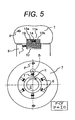
- Fig. 5 shows a structure of a rotor of a well known rotating electrical machine in JP-A No. 2008-61356 and JP-A No. 2010-4583 .
- This figure shows an axial top view (lower) and its partial enlargedview (upper) of a vertical axis water turbine generator.
- a rotating shaft 2 is at the center of the top view.
- Multiple spider arms 6 extend radially from the rotating shaft 2 in the radial direction.
- a rotor core 7 is secured via the multiple spider arms 6.
- the rotor core 7 of components forming the rotor of the rotating electrical machine of the vertical axis water turbine generator is a circular steel plate formed by arranging uniformly-shaped fan-shaped thin segment cores circumferentially, which are laminated axially while being offset circumferentially to structure the cylindrical rotor core.
- Key ways are provided to the inner circumference of the segment cores at the same pitch as the circumferentially offset pitch. Accordingly, as shown in the partial enlarged view of Fig. 5 , multiple key ways 11a are formed to the inner circumference of the cylindrically structured rotor core 7 at aligned positions.
- a key way 10 is formed also to the radial top end of each spider arm 6 extending radially from the vertical rotating shaft 2 in the radial direction.
- the key way 11a of the rotor core 7 is disposed correspondingly to the key way 10 of the radial top end of each spider arm 6.
- the spider arms 6 and the rotor core 7 are joined by inserting a T key 14 into the key ways (10 and 11a) and then inserting cotters 15 into circumferential gaps between the T key 14 and key ways (10 and 11a). Accordingly, the rotor core 7 is secured to the spider arms 6.
- the head of the T key 14 is positioned in the key way 10 of the spider arm and the foot of the T key 14 is positioned in the key way 11a of the rotor core.
- the foot of T key 14 is merely inserted into key way 11a of the rotor core, the gaps are produced. Therefore, cotters 15a and 15b are inserted into the gaps on both sides of this foot.
- a water turbine generator may perform a pumping operation.
- the rotational direction is reverse.
- the spider arms 6 and rotor core 7 engage on the right side (side of the cotter 15b) of the key way 11a to apply the pushing force because the rotor core 7 is a source of torque generation. That is, also in the water turbine, irrespective of the mode of operation generator, the pushing force is applied by the engagement on the right side.
- the spider arms 6 and rotor core 7 engage on the right side of the key way 11a to apply the pushing force and then to produce the gap 19 circumferentially on the left side of the key way 11a between the T key 14 and key way 11a. After that, the engagement occurs on the left side of the key way 11a. Further, this intermediate state is to be called a floating state, in which the active engagement is not achieved on either side.
- Fig. 6 shows relationship of the forces applied on each component at the time of the load cut off.
- the rotational direction H is maintained for electrical generation, but the pushing force f onto the right side of the key way 11a is reduced due to the large deceleration force.
- the eccentric load P of the rotor core 7 becomes larger than the restraining force F by the push of the T key 14.
- the rotor core 7 is offset in the range of the gap between the T key 14 and key way 11a to be eccentric to the spider arms 6. Accordingly, the center of gravity of the rotor core 7 is displaced relative to the center of gravity of the spider arms 6. Then, an axial runout of the rotating shaft increases by an amplification ratio or over at its rotational speed. This may cause damage of a machine.
- a rotor of a rotating electrical machine has a vertical rotating shaft, spider arms extending radially from the vertical rotating shaft, and a rotor core component provided to the outer circumference of the spider arms.
- a T key and cotters are inserted into and secured to a key way provided to the inner circumference of the rotor core component and to the abutment surface of the top end of the spider arm.
- a plate spring is mounted to a surface of the spider arm, the surface facing the rotational direction of the rotational electrical machine. The plate spring has one side engaging the spider arm, the other side engaging the rotor core component, and a middle portion fastened to the spider arm.
- the rotor core component includes a rim having cylindrically laminated fan-shaped segment rims and a rotor core on the outer circumference of the rim.
- the key ways may be provided to the inner circumference of the rim.
- the rotor core component includes a rim having cylindrically laminated ring rims and a rotor core on the outer circumference of the rim.
- the key ways may be provided to the inner circumference of the rim.
- the rotor core component includes laminated fan-shaped segment cores.
- the key ways may be provided to the inner circumference of the segment cores.
- a rotor of a rotating electrical machine includes a vertical rotating shaft, spider arms extending radially from the vertical rotating shaft, and a rotor core component provided to the outer circumference of the spider arms.
- a T key and cotters are inserted into and secured to a key way provided to the abutment surface of the inner circumference of the rotor core component and the top end of the spider arm.
- a plate spring is mounted to a surface of the spider arm, the surface being in the rotational direction of the rotational electrical machine. The plate spring has one side engaging the spider arm, the other side engaging the rotor core component, and a middle portion bolted from the opposite side of the spider arm.
- Multiple plate springs may be mounted to the spider arm axially.
- a rotating electrical machine is structured as follows.
- a pushing force of a T key applied by a plate spring is constantly applied as a restraining force of a rotor core. Even when load cut off occurs during electrical generation in the state in which circumferential gaps are produced between the T key and a key way, the rotor core is not eccentric to spider arms.
- a rotor of a water turbine generator is explained below in Figs. 1 to 8 as a rotor of a rotating electrical machine according to one embodiment of the present invention.
- Fig. 2 shows a vertical cross section of a water turbine generator of one embodiment of the present invention.
- a water turbine generator 1 includes a rotor 3 secured to a rotating shaft 2 and a stator 4 mounted via a radial gap relative to the rotor 3.
- a water turbine not shown is coupled to the lower portion of the rotating shaft 2.
- the rotating shaft 2 includes a vertical rotating shaft 5 and spider arms 6 extending radially.
- the rotor 3 includes a rotor core 7 and a rotor winding 8.
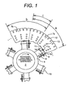
- Fig. 1 shows a transverse cross section of the water turbine generator along section A-A of Fig. 2 .
- the rotor core 7 has multiple fan-shaped thin plate segment cores 7a and 7b arranged circumferentially to have a circular shape and laminated axially while being offset circumferentially to have a cylindrical shape.
- the segment core 7b in a range b is mounted above the segment core 7a in a range a, and overlaps with the segment core 7a in a range c. In this way, the segment cores are laminated while being offset by the range c.
- Key ways 11 for joining to the spider arms 6 are provided to the inner circumference of the segment cores 7a and 7b at the same pitch as an offset pitch or at a uniform pitch.
- the multiple key ways 11 are formed to the inner circumference of the rotor core 7 structured in a cylindrical shape at axially aligned positions.
- the segment cores 7a and 7b include slots 12 on the outer circumference thereof to insert the rotor windings 8 and bolt holes 13 to fasten the laminated segment cores.
- a preventive plate 9 for eccentricity of rotor the plate of which is a plate spring for preventing eccentricity of the rotor core 7, is provided to a side of each spider arm 6, the side of which faces a rotational direction for electrical generation, and explained below in detail.
- each spider arm 6 on the rotating shaft side has a key way 10 to join to the rotor core 7.
- a T key 14 is inserted between the key way 10 of the spider arm 6 and a corresponding key way 11a of the rotor core.
- cotters 15a and 15b are inserted into circumferential gaps between the T key 14 and key way 11a to secure the rotor core 7 to each spider arm 6.
- the head of the T key 14 is positioned in the key way 10 of the spider arm 6, and the foot of the T key is positioned in the key way 11a of the rotor core 7.
- the foot of the T key is merely inserted into the key way 11a of the rotor core 7, gaps are produced on both sides of the foot. Therefore, cotters 15a and 15b are inserted into these gaps.
- the preventive plates 9 for eccentricity of rotor are attached to the spider arms 6 in the present invention.
- the preventive plates 9 for eccentricity of rotor are attached to all the spider arms 6 as shown in Fig. 1 , and may be attached to several vertical positions thereof as shown in Fig. 2 .
- the preventive plates 9 are attached toward the rotational direction for electrical generation. In Fig. 1 , since the rotational direction for electrical generation is right, the preventive plate 9 for eccentricity of rotor is attached to the right side surface of the spider arm 6.
- the preventive plate 9 for eccentricity of rotor is attached to the spider arm 6 to sandwich a key way 11b of the rotor core 7.
- the inner circumferential side of the preventive plate 9 for eccentricity of rotor is a support point against a preventive plate stopper 16 tightly secured to the spider arm 6.
- the outer circumferential top end of the preventive plate 9 for eccentricity of rotor is an action point against the key way 11b of the rotor core 7 via a receiving fitting 18.
- a bolt 17 for bolting the preventive plate for eccentricity of rotor is provided between the support point and action point of the preventive plate 9 for eccentricity of rotor to bolt and bend the preventive plate 9. Then, a pushing force q is applied between the spider arm 6 and rotor core 7 via the T key 14 and cotter 15b.
- the pushing force q is applied as a force of pushing the rotor core 7 leftward at the action point, which is the receiving fitting 18 of the key way 11b of the rotor core 7, and as a force of pushing the T key 14 rightward at the top end of the spider arm 6. That is, the pushing force is constantly applied to the right side of the key way 11a of the rotor core 7. This means that the pushing force is constantly applied to the side of the rotor core key way 11a toward the rotational direction for electrical generation.
- a magnitude of the pushing force q per one preventive plate 9 for eccentricity of rotor is over a force converted by dividing a reverse torque generated from a water turbine at load cut off by a product of an action radius, the number of the spider arms 6, and the number of the preventive plates 9 for eccentricity of rotor per one spider arm 6. That is, even at load cut off, the pushing force is applied on the right side of the key way 11a of the rotor core 7. The pushing force q sufficient not to generate a gap on the right side is necessary.
- a resultant force of the pushing forces q namely, a restraining force Q of the rotor core, is over an eccentric load P of the rotor core 7.
- the key way 11a widens due to electricity generating operation, and a circumferential gap 19 is produced between the T key 14 and key way 11a, a pushing force f applied on the right side, and the pushing force q of the preventive plate 9 for eccentricity of rotor is applied on the key way 11a toward the rotational direction for electrical generation via the T key 14 and cotter 15b.
- the pushing force is strengthened more than before.
- the preventive plate 9 for eccentricity of rotor has a plate spring structure because the adjustment of the pushing force q is easy and because excess bending stress is not applied to the preventive plate 9 for eccentricity of rotor even when a gap between the key ways 11a and 11b widens circumferentially due to a centrifugal force in operation.
- the receiving fitting 18 is provided to prevent serious wear and damage of the contact surface of the top end of the preventive plate 9 for eccentricity of rotor and the key way 11b due to, e.g., sliding.
- the receiving fitting 18 has ahooking structure not to drop out of the key way 11b, as not shown. Wear-resistant processing is applied to the contact surface of the preventive plate 9 for eccentricity of rotor and the receiving fitting 18 to reduce the frictional coefficient.
- the water turbine generator 1 including the rotor core 7 having the laminated segment cores 7a, 7b on the outer circumference of the spider arms 6 has been explained above as one example of the rotational electrical machine.
- the present invention is applicable to a rotational electrical machine structured to have segment rims 20a, 20b cylindrically laminated on the outer circumference of the spider arms as shown in Fig. 7 and to a rotational electrical machine structured to have ring rims 21 cylindrically laminated as shown in Fig. 8 .
- a key way 11b for the preventive plate for eccentricity of rotor may be provided to the inner circumference of the rim.
- the present invention has the structure for attaching the rotor core component to the outer circumference of the spider arms 6.
- the component may be the rotor core 7 having the laminated segment cores 7a, 7b or the rotor core 7 having the laminated segment rims 20a, 20b or the segment cores 7a, 7b laminated via the ring rims.
- the key way 11b for the preventive plate for eccentricity of rotor may be provided to the rotor core component.
- the present invention is applicable to prevent eccentricity of a vertical axis water turbine generator by use of a simple structure.
Landscapes
- Engineering & Computer Science (AREA)
- Power Engineering (AREA)
- Iron Core Of Rotating Electric Machines (AREA)
Abstract
Description
- The present invention relates to a rotor of a rotating electrical machine arranged vertically like a water turbine generator and particularly to a rotor of a rotating electrical machine having a cylindrical rotor core component on the outer circumference of spider arms which extend radially from a vertical rotating shaft in the radial direction and using keys to join the spider arms and cylindrical rotor core component.
- A rotor of a rotating electrical machine having a cylindrical rotor core provided to the outer circumference of spider arms is well known, e.g., in
JP-A No. 2008-61356 JP-A No. 2010-4583 -
Fig. 5 shows a structure of a rotor of a well known rotating electrical machine inJP-A No. 2008-61356 JP-A No. 2010-4583 shaft 2 is at the center of the top view.Multiple spider arms 6 extend radially from the rotatingshaft 2 in the radial direction. Arotor core 7 is secured via themultiple spider arms 6. - The
rotor core 7 of components forming the rotor of the rotating electrical machine of the vertical axis water turbine generator is a circular steel plate formed by arranging uniformly-shaped fan-shaped thin segment cores circumferentially, which are laminated axially while being offset circumferentially to structure the cylindrical rotor core. Key ways are provided to the inner circumference of the segment cores at the same pitch as the circumferentially offset pitch. Accordingly, as shown in the partial enlarged view ofFig. 5 , multiplekey ways 11a are formed to the inner circumference of the cylindrically structuredrotor core 7 at aligned positions. - On the other hand, a
key way 10 is formed also to the radial top end of eachspider arm 6 extending radially from the vertical rotatingshaft 2 in the radial direction. Thekey way 11a of therotor core 7 is disposed correspondingly to thekey way 10 of the radial top end of eachspider arm 6. - The
spider arms 6 and therotor core 7 are joined by inserting aT key 14 into the key ways (10 and 11a) and then inserting cotters 15 into circumferential gaps between theT key 14 and key ways (10 and 11a). Accordingly, therotor core 7 is secured to thespider arms 6. - Specifically, for example, the head of the
T key 14 is positioned in thekey way 10 of the spider arm and the foot of theT key 14 is positioned in thekey way 11a of the rotor core. When the foot ofT key 14 is merely inserted intokey way 11a of the rotor core, the gaps are produced. Therefore,cotters - According to this engagement structure, there is no gap between the
T key 14 andkey way 11a during the shutdown of the rotating electrical machine, but the rotor rotates when the rotating electrical machine operates to apply a stress to therotor core 7 due to centrifugal force. Then, therotor core 7 displaces to widen circumferentially and radially. Particularly, the circumferential expansion becomes large because the stress gathers around the periphery of thekey way 11a. Then, circumferential gaps are produced between the T key andkey way 11a. - During the electrical generation by the rotating electrical machine, torque from a water turbine (not shown) directly connected to the vertical rotating
shaft 2 is applied to the head of theT key 14 of the top end of eachspider arm 6 and is transmitted to therotor core 7 via the cotters 15 from the foot of theT key 14. As a result, eachspider arm 6 is pushed onto thekey way 11a in the rotational direction for electrical generation, and a resultant force F of pushing forces f is applied as a restraining force of therotor core 7 on thespider arms 6. - That is, as shown by an arrow H, when the rotational direction for electrical generation is right in
Fig .5 , thespider arms 6 androtor core 7 engage on the right side (the side of thecotter 15b) of thekey way 11a to apply the pushing force. Then, acircumferential gap 19 is produced on the left side (side of thecotter 15a) between theT key 14 andkey way 11a. - On the other hand, a force tomake the
rotor core 7 eccentric by rotation, eccentric load P, applied on therotor core 7 due to its own unbalance. Sufficient balancing can make the eccentric load P of therotor core 7 smaller than the restraining force F by the push of theT key 14. Therefore, even when thegap 19 is produced circumferentially between theT key 14 andkey way 11a during the electrical generation, therotor core 7 is not offset eccentrically to thespider arms 6. - A water turbine generator may perform a pumping operation.
- In this case, the rotational direction is reverse. The
spider arms 6 androtor core 7 engage on the right side (side of thecotter 15b) of thekey way 11a to apply the pushing force because therotor core 7 is a source of torque generation. That is, also in the water turbine, irrespective of the mode of operation generator, the pushing force is applied by the engagement on the right side. - By the way, when a load cut off and an emergency stop arise during electrical generation, a rotational speed rises temporarily to enter a dangerous situation. Thus, it is necessary to stop a water turbine by closing an inlet valve of the water turbine. In such a state, in an early over speed state, the
gap 19 between theT key 14 andkey way 11a becomes larger. After that, when the acceleration begins to decrease, the pushing force of theT key 14 by the torque from the water turbine decreases. Then, when the rotational speed reaches near the maximum to close the inlet valve of the water turbine, the reverse torque is applied on theT key 14 for deceleration in turn. The application direction of the pushing force f of theT key 14 is reversed. - That is, at the early stage of the load cut off, the
spider arms 6 androtor core 7 engage on the right side of thekey way 11a to apply the pushing force and then to produce thegap 19 circumferentially on the left side of thekey way 11a between theT key 14 andkey way 11a. After that, the engagement occurs on the left side of thekey way 11a. Further, this intermediate state is to be called a floating state, in which the active engagement is not achieved on either side. -
Fig. 6 shows relationship of the forces applied on each component at the time of the load cut off. The rotational direction H is maintained for electrical generation, but the pushing force f onto the right side of thekey way 11a is reduced due to the large deceleration force. - In this process, the eccentric load P of the
rotor core 7 becomes larger than the restraining force F by the push of theT key 14. Therotor core 7 is offset in the range of the gap between theT key 14 andkey way 11a to be eccentric to thespider arms 6. Accordingly, the center of gravity of therotor core 7 is displaced relative to the center of gravity of thespider arms 6. Then, an axial runout of the rotating shaft increases by an amplification ratio or over at its rotational speed. This may cause damage of a machine. - It is desirable to provide a rotating electrical machine in which a rotor core is not eccentric to spider arms even when a torque from a water turbine is reduced and a reverse torque is applied due to, e.g., load cut off.
- In the present invention, a rotor of a rotating electrical machine has a vertical rotating shaft, spider arms extending radially from the vertical rotating shaft, and a rotor core component provided to the outer circumference of the spider arms. A T key and cotters are inserted into and secured to a key way provided to the inner circumference of the rotor core component and to the abutment surface of the top end of the spider arm. A plate spring is mounted to a surface of the spider arm, the surface facing the rotational direction of the rotational electrical machine. The plate spring has one side engaging the spider arm, the other side engaging the rotor core component, and a middle portion fastened to the spider arm.
- The rotor core component includes a rim having cylindrically laminated fan-shaped segment rims and a rotor core on the outer circumference of the rim. The key ways may be provided to the inner circumference of the rim.
- The rotor core component includes a rim having cylindrically laminated ring rims and a rotor core on the outer circumference of the rim. The key ways may be provided to the inner circumference of the rim.
- The rotor core component includes laminated fan-shaped segment cores. The key ways may be provided to the inner circumference of the segment cores.
- In the present invention, a rotor of a rotating electrical machine includes a vertical rotating shaft, spider arms extending radially from the vertical rotating shaft, and a rotor core component provided to the outer circumference of the spider arms. A T key and cotters are inserted into and secured to a key way provided to the abutment surface of the inner circumference of the rotor core component and the top end of the spider arm. A plate spring is mounted to a surface of the spider arm, the surface being in the rotational direction of the rotational electrical machine. The plate spring has one side engaging the spider arm, the other side engaging the rotor core component, and a middle portion bolted from the opposite side of the spider arm.
- Multiple plate springs may be mounted to the spider arm axially.
- According to the present invention, a rotating electrical machine is structured as follows. A pushing force of a T key applied by a plate spring is constantly applied as a restraining force of a rotor core. Even when load cut off occurs during electrical generation in the state in which circumferential gaps are produced between the T key and a key way, the rotor core is not eccentric to spider arms.
-
-
Fig. 1 shows a transverse cross section of a water turbine generator along section A-A ofFig. 2 ; -
Fig. 2 shows a vertical cross section of the water turbine generator; -
Fig. 3 shows a joint portion of a spider arm and a rotor core and an attachment structure of a preventive plate for eccentricity of rotor; -
Fig. 4 shows a relationship of forces applied during electrical generation of awater turbine generator 1. -
Fig. 5 shows a structure of a rotor of a well known rotating electrical machine; -
Fig. 6 shows a relationship of forces applied on each component at the time of load cut off; -
Fig. 7 shows an arrangement of a preventive plate for eccentricity of rotor of the rotor when using segment rims; and -
Fig. 8 shows an arrangement of a preventive plate for eccentricity of rotor of the rotor when using ring rims. - A rotor of a water turbine generator is explained below in
Figs. 1 to 8 as a rotor of a rotating electrical machine according to one embodiment of the present invention. -
Fig. 2 shows a vertical cross section of a water turbine generator of one embodiment of the present invention. As shown in this figure, awater turbine generator 1 includes arotor 3 secured to arotating shaft 2 and astator 4 mounted via a radial gap relative to therotor 3. A water turbine not shown is coupled to the lower portion of therotating shaft 2. Therotating shaft 2 includes a verticalrotating shaft 5 andspider arms 6 extending radially. Therotor 3 includes arotor core 7 and a rotor winding 8. -
Fig. 1 shows a transverse cross section of the water turbine generator along section A-A ofFig. 2 . As shown in this figure, therotor core 7 has multiple fan-shaped thinplate segment cores Fig. 1 , thesegment core 7b in a range b is mounted above thesegment core 7a in a range a, and overlaps with thesegment core 7a in a range c. In this way, the segment cores are laminated while being offset by the range c. -
Key ways 11 for joining to thespider arms 6 are provided to the inner circumference of thesegment cores key ways 11 are formed to the inner circumference of therotor core 7 structured in a cylindrical shape at axially aligned positions. Thesegment cores slots 12 on the outer circumference thereof to insert therotor windings 8 and boltholes 13 to fasten the laminated segment cores. Apreventive plate 9 for eccentricity of rotor, the plate of which is a plate spring for preventing eccentricity of therotor core 7, is provided to a side of eachspider arm 6, the side of which faces a rotational direction for electrical generation, and explained below in detail. - On the other hand, the radial top end of each
spider arm 6 on the rotating shaft side has akey way 10 to join to therotor core 7. A Tkey 14 is inserted between thekey way 10 of thespider arm 6 and a correspondingkey way 11a of the rotor core. - As shown by the enlarged joint portion in
Fig. 3 ,cotters T key 14 andkey way 11a to secure therotor core 7 to eachspider arm 6. Specifically, the head of theT key 14 is positioned in thekey way 10 of thespider arm 6, and the foot of the T key is positioned in thekey way 11a of therotor core 7. When the foot of the T key is merely inserted into thekey way 11a of therotor core 7, gaps are produced on both sides of the foot. Therefore,cotters - Fundamentally, in the rotor of the rotating electrical machine structured as mentioned above, the
preventive plates 9 for eccentricity of rotor are attached to thespider arms 6 in the present invention. Thepreventive plates 9 for eccentricity of rotor are attached to all thespider arms 6 as shown inFig. 1 , and may be attached to several vertical positions thereof as shown inFig. 2 . Thepreventive plates 9 are attached toward the rotational direction for electrical generation. InFig. 1 , since the rotational direction for electrical generation is right, thepreventive plate 9 for eccentricity of rotor is attached to the right side surface of thespider arm 6. - As shown in
Fig. 3 , thepreventive plate 9 for eccentricity of rotor is attached to thespider arm 6 to sandwich akey way 11b of therotor core 7. The inner circumferential side of thepreventive plate 9 for eccentricity of rotor is a support point against apreventive plate stopper 16 tightly secured to thespider arm 6. The outer circumferential top end of thepreventive plate 9 for eccentricity of rotor is an action point against thekey way 11b of therotor core 7 via a receivingfitting 18. Abolt 17 for bolting the preventive plate for eccentricity of rotor is provided between the support point and action point of thepreventive plate 9 for eccentricity of rotor to bolt and bend thepreventive plate 9. Then, a pushing force q is applied between thespider arm 6 androtor core 7 via theT key 14 andcotter 15b. - The pushing force q is applied as a force of pushing the
rotor core 7 leftward at the action point, which is the receiving fitting 18 of thekey way 11b of therotor core 7, and as a force of pushing theT key 14 rightward at the top end of thespider arm 6. That is, the pushing force is constantly applied to the right side of thekey way 11a of therotor core 7. This means that the pushing force is constantly applied to the side of the rotor corekey way 11a toward the rotational direction for electrical generation. - A magnitude of the pushing force q per one
preventive plate 9 for eccentricity of rotor is over a force converted by dividing a reverse torque generated from a water turbine at load cut off by a product of an action radius, the number of thespider arms 6, and the number of thepreventive plates 9 for eccentricity of rotor per onespider arm 6. That is, even at load cut off, the pushing force is applied on the right side of thekey way 11a of therotor core 7. The pushing force q sufficient not to generate a gap on the right side is necessary. A resultant force of the pushing forces q, namely, a restraining force Q of the rotor core, is over an eccentric load P of therotor core 7. - Roles of the
preventive plates 9 for eccentricity of rotor are explained below in various operational statuses of the water turbine generator. First, as explained above usingFig. 5 andFig. 6 , when there is nopreventive plate 9 for eccentricity of rotor, the rotor core is eccentric to thespider arms 6 as shown by the dashed line ofFig. 6 . - On the other hand, according to this embodiment, when the
water turbine generator 1 shown inFig. 4 operates to generate electricity, thekey way 11a widens due to electricity generating operation, and acircumferential gap 19 is produced between theT key 14 andkey way 11a, a pushing force f applied on the right side, and the pushing force q of thepreventive plate 9 for eccentricity of rotor is applied on thekey way 11a toward the rotational direction for electrical generation via theT key 14 andcotter 15b. As a result, the contact is maintained. Therefore, the pushing force is strengthened more than before. - When torque from the water turbine is reduced and reverse torque is applied due to load cut off etc., the pushing force f on the right side is reduced due to the deceleration, but the contact is maintained by the pushing force q of the
preventive plate 9 for eccentricity of rotor, and therotor core 7 is not eccentric to thespider arms 6. - The
preventive plate 9 for eccentricity of rotor has a plate spring structure because the adjustment of the pushing force q is easy and because excess bending stress is not applied to thepreventive plate 9 for eccentricity of rotor even when a gap between thekey ways - Even when the action point at the top end of the
preventive plate 9 for eccentricity of rotor and the contact surface of theT key 14 andcotter 15b are worn due to sliding at shutdown, reduction of the pushing force can be eased. When the pushing force is reduced due to aging, the pushing force can be recovered by bolting again. - The receiving
fitting 18 is provided to prevent serious wear and damage of the contact surface of the top end of thepreventive plate 9 for eccentricity of rotor and thekey way 11b due to, e.g., sliding. The receivingfitting 18 has ahooking structure not to drop out of thekey way 11b, as not shown. Wear-resistant processing is applied to the contact surface of thepreventive plate 9 for eccentricity of rotor and the receiving fitting 18 to reduce the frictional coefficient. - Since the restraining force of the rotor core is constantly applied, the center of gravity of the rotor core is stably positioned even in no-load operation. Accordingly, the unbalance is adjusted relatively easily.
- In pumping operation, the rotational direction is reverse to transmit torque from the rotor core to the spider arms, but the transmission surface for torque between the T key and key way, the contact surface, is the same as in the electrical generation. Therefore, the pushing force is maintained in the pumping operation.
- The
water turbine generator 1 including therotor core 7 having thelaminated segment cores spider arms 6 has been explained above as one example of the rotational electrical machine. The present invention is applicable to a rotational electrical machine structured to havesegment rims Fig. 7 and to a rotational electrical machine structured to havering rims 21 cylindrically laminated as shown inFig. 8 . In this case, in addition to thekey way 11a for joining to the spider arm, akey way 11b for the preventive plate for eccentricity of rotor may be provided to the inner circumference of the rim. - In short, the present invention has the structure for attaching the rotor core component to the outer circumference of the
spider arms 6. The component may be therotor core 7 having thelaminated segment cores rotor core 7 having thelaminated segment rims segment cores key way 11a for joining to the spider arm, thekey way 11b for the preventive plate for eccentricity of rotor may be provided to the rotor core component. - The present invention is applicable to prevent eccentricity of a vertical axis water turbine generator by use of a simple structure.
Claims (6)
- A rotor of a rotating electrical machine, the rotor comprising:a vertical rotating shaft;spider arms extending radially from the vertical rotating shaft; anda rotor core component provided to an outer circumference of the spider arms,a T key and cotters being inserted into and secured to a key way provided to an abutment surface of an inner circumference of the rotor core component and a top end of the spider arm,a plate spring having one side engaging the spider arm, the other side engaging the rotor core component, and a middle portion fastened to the spider arm, andthe plate spring being mounted to a surface of the spider arm, the surface facing a rotational direction for electrical generation.
- The rotor according to claim 1,
wherein the rotor core component includes a rim having cylindrically laminated fan-shaped segment rims and a rotor core on an outer circumference of the rim, and the key way is provided to an inner circumference of the rim. - The rotor according to claim 1,
wherein the rotor core component includes a rim having cylindrically laminated ring rims and a rotor core on an outer circumference of the rim, and the key way is provided to an inner circumference of the rim. - The rotor according to claim 1,
wherein the rotor core component has laminated fan-shaped segment cores, and the key way is provided to an inner circumference of the component. - A rotor of a rotating electrical machine, the rotor comprising:a vertical rotating shaft;spider arms extending radially from the vertical rotating shaft; anda rotor core component provided to an outer circumference of the spider arms,a T key and cotters being inserted into and secured to a key way provided to an abutment surface of an inner circumference of the rotor core component and a top end of the spider arm,a plate spring having one side engaging the spider arm, the other side engaging the rotor core component, and a middle portion bolted from an opposite surface of the spider arm, andthe plate spring being mounted to a surface of the spider arm, the surface facing a rotational direction for electrical generation.
- The rotor according to claims 1 to 5, wherein a plurality of plate springs are mounted to the spider arm axially.
Priority Applications (1)
| Application Number | Priority Date | Filing Date | Title |
|---|---|---|---|
| SI201131582T SI2387132T1 (en) | 2010-05-13 | 2011-05-13 | Rotor of rotating electrical machine |
Applications Claiming Priority (1)
| Application Number | Priority Date | Filing Date | Title |
|---|---|---|---|
| JP2010110991A JP5480716B2 (en) | 2010-05-13 | 2010-05-13 | Rotating electrical machine rotor |
Publications (3)
| Publication Number | Publication Date |
|---|---|
| EP2387132A2 true EP2387132A2 (en) | 2011-11-16 |
| EP2387132A3 EP2387132A3 (en) | 2017-06-07 |
| EP2387132B1 EP2387132B1 (en) | 2018-07-04 |
Family
ID=44202200
Family Applications (1)
| Application Number | Title | Priority Date | Filing Date |
|---|---|---|---|
| EP11003995.5A Active EP2387132B1 (en) | 2010-05-13 | 2011-05-13 | Rotor of rotating electrical machine |
Country Status (6)
| Country | Link |
|---|---|
| US (1) | US8421318B2 (en) |
| EP (1) | EP2387132B1 (en) |
| JP (1) | JP5480716B2 (en) |
| ES (1) | ES2687410T3 (en) |
| LT (1) | LT2387132T (en) |
| SI (1) | SI2387132T1 (en) |
Cited By (5)
| Publication number | Priority date | Publication date | Assignee | Title |
|---|---|---|---|---|
| EP2624416A1 (en) * | 2012-02-01 | 2013-08-07 | GE Energy Power Conversion Technology Limited | A gearless drive for a rotating electrical machine |
| CN103475127A (en) * | 2013-09-25 | 2013-12-25 | 西安泰富西玛电机有限公司 | Rotor core combination key for high-speed high-power motor |
| EP3029806A1 (en) * | 2014-12-05 | 2016-06-08 | Siemens Aktiengesellschaft | Component for an electric machine |
| EP3276797A1 (en) * | 2016-07-25 | 2018-01-31 | Siemens Aktiengesellschaft | Rotor for an electric rotating machine |
| WO2019020277A1 (en) * | 2017-07-26 | 2019-01-31 | Robert Bosch Gmbh | ROTOR FOR AN ELECTRICAL MACHINE AND ELECTRIC MACHINE |
Families Citing this family (6)
| Publication number | Priority date | Publication date | Assignee | Title |
|---|---|---|---|---|
| JP5699956B2 (en) * | 2012-02-08 | 2015-04-15 | 日本精工株式会社 | Electric motor |
| ITMI20121303A1 (en) * | 2012-07-25 | 2014-01-26 | Wilic Sarl | ROTOR OF A LARGE DIAMETER ROTARY ELECTRIC MACHINE AND ROTARY ELECTRIC MACHINE |
| JP6479457B2 (en) * | 2014-12-22 | 2019-03-06 | 株式会社東芝 | Rotating electric machine and manufacturing method thereof |
| KR102239218B1 (en) * | 2019-11-18 | 2021-04-12 | 주식회사 위드피에스 | Rotor assembly of generator |
| US11870310B2 (en) * | 2020-12-14 | 2024-01-09 | Electromechanical Engineering Associates, Inc. | Method of repairing a hydrogenerator |
| CN112886736B (en) * | 2021-01-25 | 2022-02-01 | 珠海格力电器股份有限公司 | Rotor subassembly and have its motor |
Citations (2)
| Publication number | Priority date | Publication date | Assignee | Title |
|---|---|---|---|---|
| JP2008061356A (en) | 2006-08-30 | 2008-03-13 | Omron Corp | Isolated operation detection device, isolated operation detection method thereof, and power conditioner incorporating the isolated operation detection device |
| JP2010004583A (en) | 2008-06-18 | 2010-01-07 | Hitachi Ltd | Rotating electrical machine |
Family Cites Families (8)
| Publication number | Priority date | Publication date | Assignee | Title |
|---|---|---|---|---|
| US2263220A (en) * | 1939-03-20 | 1941-11-18 | Forgeo Et Ateliers De Const El | Largh high-speed rim |
| JPS4627147Y1 (en) * | 1967-10-24 | 1971-09-18 | ||
| US4110652A (en) * | 1977-03-16 | 1978-08-29 | General Electric Company | Mounting assembly for laminated rotor rim of dynamoelectric generator rotatable about inclined shaft |
| JPS5649640A (en) * | 1979-09-28 | 1981-05-06 | Hitachi Ltd | Rotor of rotating electric machine |
| JPS57129140A (en) * | 1981-02-02 | 1982-08-11 | Hitachi Ltd | Rotor for salient-pole type rotary electric machine |
| JPS57135643A (en) * | 1981-02-12 | 1982-08-21 | Hitachi Ltd | Rotor rim supporting device for rotary electric machine |
| JPH0757076B2 (en) * | 1988-05-30 | 1995-06-14 | 三菱電機株式会社 | Rotating machine rotor |
| JPH07312838A (en) * | 1994-05-17 | 1995-11-28 | Fuji Electric Co Ltd | Rotating electric machine |
-
2010
- 2010-05-13 JP JP2010110991A patent/JP5480716B2/en active Active
-
2011
- 2011-05-05 US US13/101,181 patent/US8421318B2/en active Active
- 2011-05-13 SI SI201131582T patent/SI2387132T1/en unknown
- 2011-05-13 ES ES11003995.5T patent/ES2687410T3/en active Active
- 2011-05-13 LT LTEP11003995.5T patent/LT2387132T/en unknown
- 2011-05-13 EP EP11003995.5A patent/EP2387132B1/en active Active
Patent Citations (2)
| Publication number | Priority date | Publication date | Assignee | Title |
|---|---|---|---|---|
| JP2008061356A (en) | 2006-08-30 | 2008-03-13 | Omron Corp | Isolated operation detection device, isolated operation detection method thereof, and power conditioner incorporating the isolated operation detection device |
| JP2010004583A (en) | 2008-06-18 | 2010-01-07 | Hitachi Ltd | Rotating electrical machine |
Cited By (13)
| Publication number | Priority date | Publication date | Assignee | Title |
|---|---|---|---|---|
| EP2624416A1 (en) * | 2012-02-01 | 2013-08-07 | GE Energy Power Conversion Technology Limited | A gearless drive for a rotating electrical machine |
| WO2013113803A1 (en) * | 2012-02-01 | 2013-08-08 | Ge Energy Power Conversion Technology Ltd | A gearless drive for a rotating electrical machine |
| CN104247217A (en) * | 2012-02-01 | 2014-12-24 | 通用电气能源能量变换技术有限公司 | Gearless drive for rotating electrical machine |
| CN104247217B (en) * | 2012-02-01 | 2017-06-20 | 通用电气能源能量变换技术有限公司 | Gearless drives for rotating electrical machines |
| CN103475127A (en) * | 2013-09-25 | 2013-12-25 | 西安泰富西玛电机有限公司 | Rotor core combination key for high-speed high-power motor |
| AU2015357451B2 (en) * | 2014-12-05 | 2017-05-18 | Siemens Aktiengesellschaft | Component for an electric machine |
| WO2016087230A1 (en) * | 2014-12-05 | 2016-06-09 | Siemens Aktiengesellschaft | Component for an electric machine |
| EP3029806A1 (en) * | 2014-12-05 | 2016-06-08 | Siemens Aktiengesellschaft | Component for an electric machine |
| US9935511B2 (en) | 2014-12-05 | 2018-04-03 | Siemens Aktiengesellschaft | Component for an electric machine |
| RU2653160C1 (en) * | 2014-12-05 | 2018-05-08 | Сименс Акциенгезелльшафт | Construction element for electric machine |
| EP3276797A1 (en) * | 2016-07-25 | 2018-01-31 | Siemens Aktiengesellschaft | Rotor for an electric rotating machine |
| WO2018019487A1 (en) | 2016-07-25 | 2018-02-01 | Siemens Aktiengesellschaft | Rotor for an electric rotating machine |
| WO2019020277A1 (en) * | 2017-07-26 | 2019-01-31 | Robert Bosch Gmbh | ROTOR FOR AN ELECTRICAL MACHINE AND ELECTRIC MACHINE |
Also Published As
| Publication number | Publication date |
|---|---|
| US8421318B2 (en) | 2013-04-16 |
| LT2387132T (en) | 2018-08-27 |
| EP2387132A3 (en) | 2017-06-07 |
| US20110278994A1 (en) | 2011-11-17 |
| EP2387132B1 (en) | 2018-07-04 |
| JP2011239632A (en) | 2011-11-24 |
| JP5480716B2 (en) | 2014-04-23 |
| SI2387132T1 (en) | 2018-11-30 |
| ES2687410T3 (en) | 2018-10-25 |
Similar Documents
| Publication | Publication Date | Title |
|---|---|---|
| EP2387132B1 (en) | Rotor of rotating electrical machine | |
| EP2192299B1 (en) | Wind turbine drive shaft connection arrangement | |
| US8963391B2 (en) | Decoupler shaft for high speed generator | |
| US8485936B2 (en) | Planet shaft retention in planetary gear system | |
| JP2005299651A (en) | A device for balancing rotating parts, especially turbojet rotors | |
| US11025131B2 (en) | Adaptor for generator | |
| JP2008050000A (en) | Hybrid drive unit | |
| US20100284835A1 (en) | Pump gear and pump assembly for a generator | |
| US20120170974A1 (en) | Actuating mechanism | |
| EP2136453B1 (en) | Rotating electrical machine | |
| US20100283343A1 (en) | Rotor gear for a generator | |
| JP2008298287A (en) | Fixing system for rotor of rotating fluid machine | |
| US8181455B2 (en) | Power generating apparatus of renewable energy type and method for installing hydraulic pump | |
| US20130076198A1 (en) | Rotor for electric rotating machine and method for manufacturing the same | |
| RU2482336C1 (en) | Rotor for hydraulic machine | |
| US8387729B2 (en) | Machine having electrical power system and centered drive coupling for same | |
| JP2008289219A (en) | Electric motor | |
| CN114174676A (en) | Improvements relating to main rotor turning systems for wind turbines | |
| EP3771842B1 (en) | Roller pitch bearings | |
| US9518610B2 (en) | Load coupling and method for adjusting torsional natural frequency of power train | |
| CN113494417B (en) | Pitch drive device for wind power generating set and wind power generating set | |
| EP4661260A1 (en) | Rotation device | |
| JP6277662B2 (en) | Flywheel for rotation test apparatus and rotation test apparatus | |
| CN104791191B (en) | The braking system of wind turbine generator | |
| CN114341512B (en) | Torque transmission system, drive unit and drive assembly with concentrically arranged rolling bearings |
Legal Events
| Date | Code | Title | Description |
|---|---|---|---|
| 17P | Request for examination filed |
Effective date: 20110908 |
|
| AK | Designated contracting states |
Kind code of ref document: A2 Designated state(s): AL AT BE BG CH CY CZ DE DK EE ES FI FR GB GR HR HU IE IS IT LI LT LU LV MC MK MT NL NO PL PT RO RS SE SI SK SM TR |
|
| AX | Request for extension of the european patent |
Extension state: BA ME |
|
| PUAI | Public reference made under article 153(3) epc to a published international application that has entered the european phase |
Free format text: ORIGINAL CODE: 0009012 |
|
| RAP1 | Party data changed (applicant data changed or rights of an application transferred) |
Owner name: HITACHI MITSUBISHI HYDRO CORPORATION |
|
| PUAL | Search report despatched |
Free format text: ORIGINAL CODE: 0009013 |
|
| AK | Designated contracting states |
Kind code of ref document: A3 Designated state(s): AL AT BE BG CH CY CZ DE DK EE ES FI FR GB GR HR HU IE IS IT LI LT LU LV MC MK MT NL NO PL PT RO RS SE SI SK SM TR |
|
| AX | Request for extension of the european patent |
Extension state: BA ME |
|
| RIC1 | Information provided on ipc code assigned before grant |
Ipc: H02K 1/30 20060101AFI20170503BHEP |
|
| PUAL | Search report despatched |
Free format text: ORIGINAL CODE: 0009013 |
|
| GRAP | Despatch of communication of intention to grant a patent |
Free format text: ORIGINAL CODE: EPIDOSNIGR1 |
|
| STAA | Information on the status of an ep patent application or granted ep patent |
Free format text: STATUS: GRANT OF PATENT IS INTENDED |
|
| INTG | Intention to grant announced |
Effective date: 20180110 |
|
| GRAS | Grant fee paid |
Free format text: ORIGINAL CODE: EPIDOSNIGR3 |
|
| GRAA | (expected) grant |
Free format text: ORIGINAL CODE: 0009210 |
|
| STAA | Information on the status of an ep patent application or granted ep patent |
Free format text: STATUS: THE PATENT HAS BEEN GRANTED |
|
| AK | Designated contracting states |
Kind code of ref document: B1 Designated state(s): AL AT BE BG CH CY CZ DE DK EE ES FI FR GB GR HR HU IE IS IT LI LT LU LV MC MK MT NL NO PL PT RO RS SE SI SK SM TR |
|
| REG | Reference to a national code |
Ref country code: GB Ref legal event code: FG4D |
|
| REG | Reference to a national code |
Ref country code: CH Ref legal event code: EP |
|
| REG | Reference to a national code |
Ref country code: AT Ref legal event code: REF Ref document number: 1015559 Country of ref document: AT Kind code of ref document: T Effective date: 20180715 |
|
| REG | Reference to a national code |
Ref country code: IE Ref legal event code: FG4D |
|
| REG | Reference to a national code |
Ref country code: DE Ref legal event code: R096 Ref document number: 602011049675 Country of ref document: DE |
|
| REG | Reference to a national code |
Ref country code: ES Ref legal event code: FG2A Ref document number: 2687410 Country of ref document: ES Kind code of ref document: T3 Effective date: 20181025 |
|
| REG | Reference to a national code |
Ref country code: NL Ref legal event code: MP Effective date: 20180704 |
|
| REG | Reference to a national code |
Ref country code: AT Ref legal event code: MK05 Ref document number: 1015559 Country of ref document: AT Kind code of ref document: T Effective date: 20180704 |
|
| PG25 | Lapsed in a contracting state [announced via postgrant information from national office to epo] |
Ref country code: NL Free format text: LAPSE BECAUSE OF FAILURE TO SUBMIT A TRANSLATION OF THE DESCRIPTION OR TO PAY THE FEE WITHIN THE PRESCRIBED TIME-LIMIT Effective date: 20180704 |
|
| PG25 | Lapsed in a contracting state [announced via postgrant information from national office to epo] |
Ref country code: FI Free format text: LAPSE BECAUSE OF FAILURE TO SUBMIT A TRANSLATION OF THE DESCRIPTION OR TO PAY THE FEE WITHIN THE PRESCRIBED TIME-LIMIT Effective date: 20180704 Ref country code: RS Free format text: LAPSE BECAUSE OF FAILURE TO SUBMIT A TRANSLATION OF THE DESCRIPTION OR TO PAY THE FEE WITHIN THE PRESCRIBED TIME-LIMIT Effective date: 20180704 Ref country code: IS Free format text: LAPSE BECAUSE OF FAILURE TO SUBMIT A TRANSLATION OF THE DESCRIPTION OR TO PAY THE FEE WITHIN THE PRESCRIBED TIME-LIMIT Effective date: 20181104 Ref country code: PL Free format text: LAPSE BECAUSE OF FAILURE TO SUBMIT A TRANSLATION OF THE DESCRIPTION OR TO PAY THE FEE WITHIN THE PRESCRIBED TIME-LIMIT Effective date: 20180704 Ref country code: SE Free format text: LAPSE BECAUSE OF FAILURE TO SUBMIT A TRANSLATION OF THE DESCRIPTION OR TO PAY THE FEE WITHIN THE PRESCRIBED TIME-LIMIT Effective date: 20180704 Ref country code: NO Free format text: LAPSE BECAUSE OF FAILURE TO SUBMIT A TRANSLATION OF THE DESCRIPTION OR TO PAY THE FEE WITHIN THE PRESCRIBED TIME-LIMIT Effective date: 20181004 Ref country code: GR Free format text: LAPSE BECAUSE OF FAILURE TO SUBMIT A TRANSLATION OF THE DESCRIPTION OR TO PAY THE FEE WITHIN THE PRESCRIBED TIME-LIMIT Effective date: 20181005 Ref country code: AT Free format text: LAPSE BECAUSE OF FAILURE TO SUBMIT A TRANSLATION OF THE DESCRIPTION OR TO PAY THE FEE WITHIN THE PRESCRIBED TIME-LIMIT Effective date: 20180704 Ref country code: BG Free format text: LAPSE BECAUSE OF FAILURE TO SUBMIT A TRANSLATION OF THE DESCRIPTION OR TO PAY THE FEE WITHIN THE PRESCRIBED TIME-LIMIT Effective date: 20181004 Ref country code: CZ Free format text: LAPSE BECAUSE OF FAILURE TO SUBMIT A TRANSLATION OF THE DESCRIPTION OR TO PAY THE FEE WITHIN THE PRESCRIBED TIME-LIMIT Effective date: 20180704 |
|
| PG25 | Lapsed in a contracting state [announced via postgrant information from national office to epo] |
Ref country code: LV Free format text: LAPSE BECAUSE OF FAILURE TO SUBMIT A TRANSLATION OF THE DESCRIPTION OR TO PAY THE FEE WITHIN THE PRESCRIBED TIME-LIMIT Effective date: 20180704 Ref country code: HR Free format text: LAPSE BECAUSE OF FAILURE TO SUBMIT A TRANSLATION OF THE DESCRIPTION OR TO PAY THE FEE WITHIN THE PRESCRIBED TIME-LIMIT Effective date: 20180704 Ref country code: AL Free format text: LAPSE BECAUSE OF FAILURE TO SUBMIT A TRANSLATION OF THE DESCRIPTION OR TO PAY THE FEE WITHIN THE PRESCRIBED TIME-LIMIT Effective date: 20180704 |
|
| REG | Reference to a national code |
Ref country code: DE Ref legal event code: R097 Ref document number: 602011049675 Country of ref document: DE |
|
| PG25 | Lapsed in a contracting state [announced via postgrant information from national office to epo] |
Ref country code: IT Free format text: LAPSE BECAUSE OF FAILURE TO SUBMIT A TRANSLATION OF THE DESCRIPTION OR TO PAY THE FEE WITHIN THE PRESCRIBED TIME-LIMIT Effective date: 20180704 Ref country code: RO Free format text: LAPSE BECAUSE OF FAILURE TO SUBMIT A TRANSLATION OF THE DESCRIPTION OR TO PAY THE FEE WITHIN THE PRESCRIBED TIME-LIMIT Effective date: 20180704 Ref country code: EE Free format text: LAPSE BECAUSE OF FAILURE TO SUBMIT A TRANSLATION OF THE DESCRIPTION OR TO PAY THE FEE WITHIN THE PRESCRIBED TIME-LIMIT Effective date: 20180704 |
|
| PLBE | No opposition filed within time limit |
Free format text: ORIGINAL CODE: 0009261 |
|
| STAA | Information on the status of an ep patent application or granted ep patent |
Free format text: STATUS: NO OPPOSITION FILED WITHIN TIME LIMIT |
|
| PG25 | Lapsed in a contracting state [announced via postgrant information from national office to epo] |
Ref country code: DK Free format text: LAPSE BECAUSE OF FAILURE TO SUBMIT A TRANSLATION OF THE DESCRIPTION OR TO PAY THE FEE WITHIN THE PRESCRIBED TIME-LIMIT Effective date: 20180704 Ref country code: SK Free format text: LAPSE BECAUSE OF FAILURE TO SUBMIT A TRANSLATION OF THE DESCRIPTION OR TO PAY THE FEE WITHIN THE PRESCRIBED TIME-LIMIT Effective date: 20180704 Ref country code: SM Free format text: LAPSE BECAUSE OF FAILURE TO SUBMIT A TRANSLATION OF THE DESCRIPTION OR TO PAY THE FEE WITHIN THE PRESCRIBED TIME-LIMIT Effective date: 20180704 |
|
| 26N | No opposition filed |
Effective date: 20190405 |
|
| REG | Reference to a national code |
Ref country code: DE Ref legal event code: R119 Ref document number: 602011049675 Country of ref document: DE |
|
| REG | Reference to a national code |
Ref country code: CH Ref legal event code: PL |
|
| PG25 | Lapsed in a contracting state [announced via postgrant information from national office to epo] |
Ref country code: LI Free format text: LAPSE BECAUSE OF NON-PAYMENT OF DUE FEES Effective date: 20190531 Ref country code: CH Free format text: LAPSE BECAUSE OF NON-PAYMENT OF DUE FEES Effective date: 20190531 Ref country code: MC Free format text: LAPSE BECAUSE OF FAILURE TO SUBMIT A TRANSLATION OF THE DESCRIPTION OR TO PAY THE FEE WITHIN THE PRESCRIBED TIME-LIMIT Effective date: 20180704 |
|
| REG | Reference to a national code |
Ref country code: BE Ref legal event code: MM Effective date: 20190531 |
|
| PG25 | Lapsed in a contracting state [announced via postgrant information from national office to epo] |
Ref country code: LU Free format text: LAPSE BECAUSE OF NON-PAYMENT OF DUE FEES Effective date: 20190513 |
|
| PG25 | Lapsed in a contracting state [announced via postgrant information from national office to epo] |
Ref country code: IE Free format text: LAPSE BECAUSE OF NON-PAYMENT OF DUE FEES Effective date: 20190513 Ref country code: DE Free format text: LAPSE BECAUSE OF NON-PAYMENT OF DUE FEES Effective date: 20191203 |
|
| PG25 | Lapsed in a contracting state [announced via postgrant information from national office to epo] |
Ref country code: BE Free format text: LAPSE BECAUSE OF NON-PAYMENT OF DUE FEES Effective date: 20190531 |
|
| PG25 | Lapsed in a contracting state [announced via postgrant information from national office to epo] |
Ref country code: PT Free format text: LAPSE BECAUSE OF FAILURE TO SUBMIT A TRANSLATION OF THE DESCRIPTION OR TO PAY THE FEE WITHIN THE PRESCRIBED TIME-LIMIT Effective date: 20181105 Ref country code: FR Free format text: LAPSE BECAUSE OF NON-PAYMENT OF DUE FEES Effective date: 20190531 |
|
| PG25 | Lapsed in a contracting state [announced via postgrant information from national office to epo] |
Ref country code: CY Free format text: LAPSE BECAUSE OF FAILURE TO SUBMIT A TRANSLATION OF THE DESCRIPTION OR TO PAY THE FEE WITHIN THE PRESCRIBED TIME-LIMIT Effective date: 20180704 |
|
| PG25 | Lapsed in a contracting state [announced via postgrant information from national office to epo] |
Ref country code: HU Free format text: LAPSE BECAUSE OF FAILURE TO SUBMIT A TRANSLATION OF THE DESCRIPTION OR TO PAY THE FEE WITHIN THE PRESCRIBED TIME-LIMIT; INVALID AB INITIO Effective date: 20110513 Ref country code: MT Free format text: LAPSE BECAUSE OF FAILURE TO SUBMIT A TRANSLATION OF THE DESCRIPTION OR TO PAY THE FEE WITHIN THE PRESCRIBED TIME-LIMIT Effective date: 20180704 |
|
| PG25 | Lapsed in a contracting state [announced via postgrant information from national office to epo] |
Ref country code: MK Free format text: LAPSE BECAUSE OF FAILURE TO SUBMIT A TRANSLATION OF THE DESCRIPTION OR TO PAY THE FEE WITHIN THE PRESCRIBED TIME-LIMIT Effective date: 20180704 |
|
| PGFP | Annual fee paid to national office [announced via postgrant information from national office to epo] |
Ref country code: ES Payment date: 20250627 Year of fee payment: 15 |
|
| PGFP | Annual fee paid to national office [announced via postgrant information from national office to epo] |
Ref country code: GB Payment date: 20260521 Year of fee payment: 16 |
|
| PGFP | Annual fee paid to national office [announced via postgrant information from national office to epo] |
Ref country code: LT Payment date: 20260423 Year of fee payment: 16 |
|
| PGFP | Annual fee paid to national office [announced via postgrant information from national office to epo] |
Ref country code: TR Payment date: 20260507 Year of fee payment: 16 |
|
| PGFP | Annual fee paid to national office [announced via postgrant information from national office to epo] |
Ref country code: SI Payment date: 20260430 Year of fee payment: 16 |