EP2386908A2 - Printing apparatus and control method for printing apparatus - Google Patents
Printing apparatus and control method for printing apparatus Download PDFInfo
- Publication number
- EP2386908A2 EP2386908A2 EP11165227A EP11165227A EP2386908A2 EP 2386908 A2 EP2386908 A2 EP 2386908A2 EP 11165227 A EP11165227 A EP 11165227A EP 11165227 A EP11165227 A EP 11165227A EP 2386908 A2 EP2386908 A2 EP 2386908A2
- Authority
- EP
- European Patent Office
- Prior art keywords
- storing means
- depleted
- printing
- specific
- toner cartridge
- Prior art date
- Legal status (The legal status is an assumption and is not a legal conclusion. Google has not performed a legal analysis and makes no representation as to the accuracy of the status listed.)
- Withdrawn
Links
- 238000000034 method Methods 0.000 title claims description 18
- 239000000463 material Substances 0.000 claims abstract description 44
- 238000012545 processing Methods 0.000 description 22
- 238000004891 communication Methods 0.000 description 11
- 230000006870 function Effects 0.000 description 9
- 238000012546 transfer Methods 0.000 description 9
- 230000003111 delayed effect Effects 0.000 description 7
- 230000004044 response Effects 0.000 description 5
- 238000010586 diagram Methods 0.000 description 4
- KNMAVSAGTYIFJF-UHFFFAOYSA-N 1-[2-[(2-hydroxy-3-phenoxypropyl)amino]ethylamino]-3-phenoxypropan-2-ol;dihydrochloride Chemical compound Cl.Cl.C=1C=CC=CC=1OCC(O)CNCCNCC(O)COC1=CC=CC=C1 KNMAVSAGTYIFJF-UHFFFAOYSA-N 0.000 description 2
- 239000003086 colorant Substances 0.000 description 2
- 238000001514 detection method Methods 0.000 description 2
- 239000000725 suspension Substances 0.000 description 2
- 230000002452 interceptive effect Effects 0.000 description 1
- 238000012986 modification Methods 0.000 description 1
- 230000004048 modification Effects 0.000 description 1
- 238000006386 neutralization reaction Methods 0.000 description 1
- 230000003287 optical effect Effects 0.000 description 1
- 238000003825 pressing Methods 0.000 description 1
Images



Classifications
-
- G—PHYSICS
- G03—PHOTOGRAPHY; CINEMATOGRAPHY; ANALOGOUS TECHNIQUES USING WAVES OTHER THAN OPTICAL WAVES; ELECTROGRAPHY; HOLOGRAPHY
- G03G—ELECTROGRAPHY; ELECTROPHOTOGRAPHY; MAGNETOGRAPHY
- G03G15/00—Apparatus for electrographic processes using a charge pattern
- G03G15/55—Self-diagnostics; Malfunction or lifetime display
- G03G15/553—Monitoring or warning means for exhaustion or lifetime end of consumables, e.g. indication of insufficient copy sheet quantity for a job
-
- G—PHYSICS
- G03—PHOTOGRAPHY; CINEMATOGRAPHY; ANALOGOUS TECHNIQUES USING WAVES OTHER THAN OPTICAL WAVES; ELECTROGRAPHY; HOLOGRAPHY
- G03G—ELECTROGRAPHY; ELECTROPHOTOGRAPHY; MAGNETOGRAPHY
- G03G15/00—Apparatus for electrographic processes using a charge pattern
- G03G15/01—Apparatus for electrographic processes using a charge pattern for producing multicoloured copies
- G03G15/0105—Details of unit
- G03G15/0126—Details of unit using a solid developer
-
- G—PHYSICS
- G03—PHOTOGRAPHY; CINEMATOGRAPHY; ANALOGOUS TECHNIQUES USING WAVES OTHER THAN OPTICAL WAVES; ELECTROGRAPHY; HOLOGRAPHY
- G03G—ELECTROGRAPHY; ELECTROPHOTOGRAPHY; MAGNETOGRAPHY
- G03G15/00—Apparatus for electrographic processes using a charge pattern
- G03G15/06—Apparatus for electrographic processes using a charge pattern for developing
- G03G15/08—Apparatus for electrographic processes using a charge pattern for developing using a solid developer, e.g. powder developer
- G03G15/0894—Reconditioning of the developer unit, i.e. reusing or recycling parts of the unit, e.g. resealing of the unit before refilling with toner
-
- G—PHYSICS
- G03—PHOTOGRAPHY; CINEMATOGRAPHY; ANALOGOUS TECHNIQUES USING WAVES OTHER THAN OPTICAL WAVES; ELECTROGRAPHY; HOLOGRAPHY
- G03G—ELECTROGRAPHY; ELECTROPHOTOGRAPHY; MAGNETOGRAPHY
- G03G15/00—Apparatus for electrographic processes using a charge pattern
- G03G15/55—Self-diagnostics; Malfunction or lifetime display
- G03G15/553—Monitoring or warning means for exhaustion or lifetime end of consumables, e.g. indication of insufficient copy sheet quantity for a job
- G03G15/556—Monitoring or warning means for exhaustion or lifetime end of consumables, e.g. indication of insufficient copy sheet quantity for a job for toner consumption, e.g. pixel counting, toner coverage detection or toner density measurement
Definitions
- the present invention relates to a printing apparatus for printing using a recording material and, in particular, to a printing apparatus having a plurality of storing units storing the recording material.
- Japanese Patent Application Laid-Open No. 2003-323027 discusses a printing apparatus that prints data by rotating and moving a plurality of toner cartridges, in which when toner is exhausted in one toner cartridge, the toner cartridge is then moved to a replaceable position, and a user can replace the toner cartridge.
- a standby position (home position) of a toner cartridge is provided to start printing most quickly.
- the printing apparatus can start printing most quickly.
- the printing apparatus temporarily moves the toner cartridge to the standby position and then executes printing. Therefore, the start of printing of the first page is delayed. Thus, first printing is delayed.
- the present invention is directed to a printing apparatus capable of starting printing using a specific storing unit quickly as much as possible if the specific storing unit is not lacking in a recording material even when it is determined that any one of a plurality of storing units storing a recording material is lacking in the recording material.
- a printing apparatus as specified in claims 1 to 8.
- a control method as specified in claims 9 to 12.
- Fig. 1 illustrates an internal configuration of a color laser printer of the rotational developing rotary type as an example of a printing apparatus according to an exemplary embodiment of the present invention.
- Fig. 2 is a block diagram illustrating a configuration of a printing system according to an exemplary embodiment of the present invention.
- Fig. 3 is a block diagram illustrating a functional configuration for printer control by a central processing unit (CPU) in a printing apparatus in Fig. 2 .
- CPU central processing unit
- Fig. 4 illustrates a method for replacing a toner cartridge in the color laser printer of the rotational developing rotary type.
- Fig. 5 is a flowchart of first processing executed by a toner cartridge control unit according to an exemplary embodiment of the present invention.
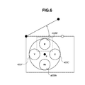
- Fig. 6 illustrates a state in which a toner cartridge for magenta is moved to a replaceable position when toner of the toner cartridge for magenta is exhausted.
- Fig. 7 illustrates a flowchart of second processing executed by the toner cartridge control unit according to an exemplary embodiment of the present invention.
- Fig. 1 illustrates an internal configuration of a color laser printer of the rotational developing rotary type as an example of a printing apparatus 200 according to an exemplary embodiment of the present invention.
- the printing apparatus 200 is illustrated as an example, using toner as a recording material for printing.
- a scanner 711 includes a laser output unit (not illustrated) that converts an image signal from a printer controller 210 into an optical signal (laser beams), a polygon mirror 712 as an octahedral member, a motor (not illustrated) that rotates the polygon mirror 712, and an f/ ⁇ lens (image-forming lens) 713.
- the laser beams output from the laser output unit are reflected by one side surface of the polygon mirror 712, pass through the f/ ⁇ lens 713, reflect from a reflection mirror 714, and linearly raster-scan a surface of a photosensitive drum 715.
- the photosensitive drum 715 is rotated in the direction illustrated by an arrow.
- an electrostatic latent image corresponding to an image represented by the image signal is formed on the surface of the photosensitive drum 715.
- a primary charger 717, a whole-surface exposure lamp 718, a cleaner unit 723 for recovering the remaining toner that is not transferred to a sheet, and a pre-transfer charger 724 are arranged around the photosensitive drum 715.
- a developing unit 726 develops the electrostatic latent image formed on the surface of the photosensitive drum 715 with the following configuration.
- Toner hoppers 730Y, 730M, 730C, and 730Bk each contain toner as a developer.
- Screws 732 transmit the developers stored in the toner hoppers 730Y, 730M, 730C, and 730Bk to developing sleeves 731Y, 731M, 731C, and 731Bk.
- the developing sleeves 731Y, 731M, 731C, and 731Bk come into contact with the photosensitive drum 715, and develop images with the developers. More specifically, toner images are formed with yellow, magenta, cyan, and black developers on the photosensitive drum 715.
- the toner hoppers 730Y, 730M, 730C, and 730Bk, the developing sleeves 731Y, 731M, 731C, and 731Bk, and the screws 732 are arranged around a central axis P of the developing unit 726.
- Different colors Y, M, C, and Bk are yellow, magenta, cyan, and black, respectively.
- the toner cartridge for each color includes the toner hopper and the developing sleeve.
- a position sensor 742 detects the rotational position of the developing unit 726.
- the developing unit 726 When forming a yellow toner image on the photosensitive drum 715, the developing unit 726 is rotated around the central axis P, and the photosensitive drum 715 comes into contact with the developing sleeve 731Y.
- Fig. 1 illustrates this status.
- the developing unit 726 When forming a magenta toner image, the developing unit 726 is rotated around the central axis P, and the photosensitive drum 715 comes into contact with the developing sleeve 731M.
- similar operations are performed.
- a transfer drum 716 transfers the toner images formed on the photosensitive drum 715 to the sheet.
- An actuator plate 719 detects a movement position of the transfer drum 716.
- a position sensor 720 which is located close to the actuator plate 719, detects that the transfer drum 716 is moved to the home position.
- the actuator plate 719, the position sensor 720, a transfer drum cleaner unit 725, a sheet pressing roller 727, and a neutralization device 729 as transfer chargers are arranged around the transfer drum 716.
- Sheet feeder cassettes 735 and 736 store sheets 791.
- the sheet feeder cassette 735 contains A4-size sheets
- the sheet feeder cassette 736 contains A3-size sheets.
- sheet feeder rollers 737 and 738 feed the sheets 791 from the sheet feeder cassettes 735 and 736.
- Timing rollers 739, 740, and 741 control the timing for feeding and conveying the sheets 791.
- the sheets 791 are guided to a sheet guide 743 via the timing rollers 739, 740, and 741.
- a gripper 728 carries the edge of the sheet and the sheet is wound around the transfer drum 716.
- One of the sheet feeder cassettes 735 and 736 is selected in response to an instruction from the printer controller 210. Only one of the sheet feeder rollers 737 and 738 corresponding to the selected sheet feeder cassette is rotated.
- the printer controller 210 is closed or opened like a door and functions as a cover, at which a user can replace the toner cartridge.
- Fig. 2 is a block diagram illustrating a configuration of a printing system according to an exemplary embodiment of the present invention.
- a host computer 100 can communicate with the printing apparatus 200 via a communication medium 150.
- the communication medium 150 is an interactive interface, such as a local area network (LAN), a universal serial bus (USB) cable, or a wireless LAN.
- LAN local area network
- USB universal serial bus
- a central processing unit (CPU) 101 processes a document comprising one or more of a graphic, an image, a character, or a table (including spreadsheet) based on a program stored in a read-only memory (ROM) 103 or a hard disk drive (HDD) (not illustrated).
- the CPU 101 comprehensively controls devices connected to a system bus 104 based on the program stored in the ROM 103 or the HDD.
- a random access memory (RAM) 102 functions as a main memory or a work area for the CPU 101.
- the ROM 103 includes a program ROM that stores various programs executed by the CPU 101, a font ROM that stores font data used for document processing, and a data ROM that stores various data used for document processing.
- a keyboard controller (KBC) 105 controls a key input from a keyboard 109 or a pointing device (not illustrated), thereby transmitting contents of the key input to the CPU 101.
- a cathode ray tube (CRT) controller (CRTC) 106 controls a display operation on a cathode ray tube (CRT) display 110 in response to an instruction from the CPU 101.
- a memory controller (MC) 107 controls the access to an external memory 111 such as a hard disk, a compact disc (CD), or a digital versatile disc (DVD).
- the external memory 111 stores a boot program, various application programs, font data, a user file, or an editing file.
- a communication control unit 108 is connected to the printing apparatus 200 via the communication medium 150, and controls the communication with the printing apparatus 200.
- the CPU 101 loads (performs rasterizing processing of) an outline font to a random access memory (RAM) for display arranged on the RAM 102 to enable the execution of "What You See Is What You Get” (WYSIWYG) on the CRT display 110.
- the CPU 101 opens various registered windows and executes various data processing in response to a command instructed with a mouse cursor displayed on the CRT display 110.
- a central processing unit (CPU) 201 comprehensively controls devices connected to a system bus 204 based on a program stored in a read-only memory (ROM) 203 or a hard disk drive (HDD) 240.
- the CPU 201 outputs an image signal to a printing unit 220 via a printing unit interface (printing unit I/F) 205 based on the program stored in the ROM 203 or the HDD 240, and controls the printing unit 220 to print an image represented by an image signal.
- ROM read-only memory
- HDD hard disk drive
- a random access memory (RAM) 202 functions as a main memory or a work area for the CPU 201.
- An optional RAM is connected to an expansion port (not illustrated), thereby expanding a memory capacity of the RAM 202.
- the RAM 202 is used as a storage area that stores a drawing memory for storing image data converted from print data.
- the ROM 203 functions as a program ROM that stores a control program based on a flowchart illustrated in Fig. 5 or 6 .
- a communication control unit 207 is connected to the host computer 100 via the communication medium 150, and controls the communication with the host computer 100.
- the CPU 201 can communicate with the host computer 100 via the communication control unit 207, and can notify the host computer 100 of status information indicating the status of the printing apparatus 200.
- An operation panel 230 includes a switch for operating the printing apparatus 200 by the user and a light-emitting diode (LED) display for displaying various information to the user. Further, the operation panel 230 may have a touch panel having a reception function of the operation and a display function of information.
- LED light-emitting diode
- a memory controller (MC) 206 controls the access to the HDD 240.
- the HDD 240 stores a program executed by the CPU 201 or print data received from the host computer 100.
- Fig. 3 is a block diagram illustrating a functional configuration of printer control by the CPU 201 in the printing apparatus 200 illustrated in Fig. 2 .
- the CPU 201 executes the program, thereby implementing an analysis unit 301, an image generation unit 302, a printing control unit 303, and a toner cartridge control unit 304.
- the communication control unit 207 receives print data or a control command from the host computer 100, and transmits the data or command to the analysis unit 301.
- the analysis unit 301 includes a control program conforming to a control command system or a control program conforming to a print control language used for print data. Therefore, the analysis unit 301 interprets print data for drawing a character, graphic, or image, and transmits printing information based on the interpretation result to the image generation unit 302.
- the analysis unit 301 interprets a control command for instructing the selection of the sheet feeder cassette or the resetting of the printing unit 220, and sends the instruction based on the interpretation to the printing control unit 303.
- the image generation unit 302 expands objects such as a character, a graphic, and an image to a bit map based on the printing information from the analysis unit 301, and stores bit map data on the RAM 202.
- the printing control unit 303 controls the printing unit 220 according to the instruction from the analysis unit 301, converts the bit map data stored in the RAM 202 into a video signal (image signal), and outputs the video signal to the printing unit 220.
- the toner cartridge control unit 304 moves the toner cartridge to the printing unit 220, and causes the printing unit 220 to execute the initialization operation, thus executing processing illustrated in Fig. 5 .
- the printing unit 220 receives a video signal from the printing control unit 303, and prints an image represented by the video signal on a sheet.
- An example of printing processing by the printing unit 220 is described above with reference to Fig. 1 .
- Fig. 4 illustrates a method for replacing the toner cartridge in the color laser printer of the rotational developing rotary type.
- the door 400 functions as a conver.
- a position 401 ]just below the door 400 then becomes a position (hereinafter, referred to as a replaceable position) for replacing the toner cartridge, and the user can replace the toner cartridge located at the position 401.
- the replaceable position of the toner cartridge is not limited to the example illustrated in Fig. 4 , and may be varied depending on the configuration of the printing apparatus 200.
- the toner cartridge 403C is for cyan
- the toner cartridge 403M is for magenta
- the toner cartridge 403Y is for yellow
- the toner cartridge 403Bk is for black.
- the toner cartridge 403Bk is located at the replaceable position.
- the toner cartridges 403C, 403M, 403Y, and 403Bk are attached to a developing unit 402, which is rotatable around the central axis P.
- the toner cartridge control unit 304 issues a control command to the printing unit 220, thereby rotating the developing unit 402 to move an arbitrary toner cartridge to the replaceable position.
- the printer of the rotational developing rotary type there is a cartridge status capable of starting printing most quickly, specifically, a standby position of the cartridge capable of starting printing most quickly.
- the printer moves the cartridge to the standby position and then executes printing. Therefore, the start of printing is delayed.
- first printing is delayed. Accordingly, the present exemplary embodiment aims at preventing the delay of starting monochrome printing by performing processing, which will be described.
- Fig. 5 is a flowchart of first processing executed by the toner cartridge control unit 304 according to an exemplary embodiment of the present invention.
- step S501 the toner cartridge control unit 304 determines whether printing starts.
- the printing control unit 303 may notify the toner cartridge control unit 304 whether printing starts.
- the toner cartridge control unit 304 monitors a status of each of the toner cartridges, and detects whether an exhausted toner cartridge is detected.
- the printing unit 220 includes a sensor that detects whether the toner is present or absent for each of a plurality of toner cartridges, and transmits a signal indicating the detection result to the toner cartridge control unit 304.
- the toner cartridge control unit 304 determines in which toner cartridge the toner is exhausted by checking the signal transmitted from the printing unit 220. According to the present exemplary embodiment, it is determined by detecting the toner exhaustion that a toner cartridge is lacking in toner.
- step S503 the toner cartridge control unit 304 determines whether printing ends.
- the print control unit 303 also notifies the toner cartridge control unit 304 whether printing ends.
- the toner cartridge control unit 304 monitors the presence or absence of an exhausted toner cartridge during a period from the start of printing to the end thereof.
- step S504 When an exhausted toner cartridge is detected (YES in step S502) , then in step S504, the toner cartridge control unit 304 performs printing suspension processing. In the printing suspension processing, the toner cartridge control unit 304 requests the print control unit 303 to suspend printing. The print control unit 303 suspends the printing operation of the printing unit 220. Thereafter, in step S505, the toner cartridge control unit 304 determines whether the printing operation of the printing unit 220 has been suspended.
- step S506 the toner cartridge control unit 304 moves the exhausted toner cartridge to the replaceable position.
- Fig. 6 illustrates a state in which the toner cartridge for magenta is moved to the replaceable position when toner of the toner cartridge for magenta is exhausted. Referring to Fig. 6 , the user can open the door 400 to replace the toner cartridge for magenta.
- step S507 the toner cartridge control unit 304 determines whether the exhausted toner cartridge has been replaced.
- a detection method of the replacement of the toner cartridge includes, e.g., a method for detecting the remaining amount of toner in the toner cartridge by the sensor after the door 400 is opened and closed. When the remaining amount of toner is detected and a sufficient amount of toner is then recognized, the toner cartridge control unit 304 determines that the toner cartridge has been replaced. There is another method for detecting the removal of the toner cartridge and attaching another toner cartridge by the sensor.
- step S508 the toner cartridge control unit 304 performs printing resumption processing.
- the toner cartridge control unit 304 requests the print control unit 303 to resume printing.
- the print control unit 303 causes the printing unit 220 to resume printing.
- step S509 the toner cartridge control unit 304 determines whether the print job in progress of printing has been canceled.
- the print control unit 303 notifies the toner cartridge control unit 304 whether the print job has been canceled.
- the print control unit 303 cancels the print job in response to the order.
- the printing apparatus 200 receives a control command for ordering the cancel of the print job from the host computer 100.
- the analysis unit 301 receives the control command from the communication control unit 207, and instructs the print control unit 303 to cancel the print job.
- the print control unit 303 cancels the print job in response to the instruction.
- the toner cartridge control unit 304 checks for which color the exhausted toner cartridge is. In step S510, the toner cartridge control unit 304 determines whether the exhausted toner cartridge is for black.
- step S511 the toner cartridge control unit 304 moves the toner cartridge for black to a specific position capable of starting monochrome printing most quickly. As a consequence, monochrome printing can start quickly.
- a position at which the toner cartridge for black is in contact with the photosensitive drum 715 is the position capable of starting monochrome printing most quickly (in Fig. 1 , the toner cartridge for yellow is in contact with the photosensitive drum 715).
- the position capable of starting monochrome printing most quickly is not limited to this, and may be varied depending on a control manner of the printer controller 210 or a configuration of the printing unit 220.
- the toner cartridge for black is made to remain at the replaceable position.
- processing is performed for detecting an exhausted toner cartridge during printing.
- processing for detecting an exhausted toner cartridge during a printing standby state is described.
- Fig. 7 is a flowchart of second processing executed by the toner cartridge control unit 304 according to an exemplary embodiment of the present invention.
- step S701 the toner cartridge control unit 304 determines whether there is an exhausted toner cartridge.
- step S702 the toner cartridge control unit 304 checks for which color the exhausted toner cartridge is, and determines whether the exhausted toner cartridge is for black.
- step S703 the toner cartridge control unit 304 moves the toner cartridge for black to the replaceable position.
- step S704 the toner cartridge control unit 304 moves the toner cartridge for black to the standby position capable of starting monochrome printing most quickly. Even if the exhausted toner cartridge is not for black, when the user instructs the replacement of the toner cartridge via the operation panel 230, the toner cartridge control unit 304 moves the toner cartridge to the replaceable position.
- the toner cartridge when toner of the toner cartridge for color other than black is exhausted, the toner cartridge is set to the standby position capable of starting monochrome printing most quickly.
- the toner cartridge control unit 304 moves the exhausted toner cartridge to the replaceable position. Automatically moving the exhausted toner cartridge to the replaceable position enables the user to replace the toner cartridge promptly. Thus, usability can be improved.
- the processing illustrated in Figs. 5 and 7 moves a specific toner cartridge, such as a toner cartridge for black, to a specific position in preparation for printing using only the specific toner cartridge, thus preventing the delay for starting that printing.
- a specific toner cartridge such as a toner cartridge for black
- the specific toner cartridge is not limited to the toner cartridge for black, and the toner cartridge for another color may be used depending on the type of the printing apparatus.
- the specific position may be different from that in Fig. 1 depending on the type of the printing apparatus.
- a specific storing unit in a printing apparatus including a plurality of storing units storing a recording material, if a specific storing unit is not lacking in the recording material, it is possible to prevent the delay for starting printing using the specific storing unit.
- aspects of the present invention can also be realized by a computer of a system or apparatus (or devices such as a CPU or MPU) that reads out and executes a program recorded on a memory device to perform the functions of the above-described embodiment (s), and by a method, the steps of which are performed by a computer of a system or apparatus by, for example, reading out and executing a program recorded on a memory device to perform the functions of the above-described embodiment(s).
- the program is provided to the computer for example via a network or from a recording medium of various types serving as the memory device (e.g., computer-readable medium).
- the present invention also provides a printing apparatus for performing printing using a recording material, the printing apparatus comprising:
- the present invention further provides a printing apparatus for performing printing using a recording material, the printing apparatus comprising:
- the present invention also provides a control method for a printing apparatus for performing printing using a recording material, the printing apparatus including a plurality of storing means for storing the recording material, the control method comprising:
- the present invention further provides a control method for a printing apparatus for performing printing using a recording material, the printing apparatus including a plurality of storing means for storing the recording material, the control method comprising:
Landscapes
- Physics & Mathematics (AREA)
- General Physics & Mathematics (AREA)
- Life Sciences & Earth Sciences (AREA)
- Sustainable Development (AREA)
- Control Or Security For Electrophotography (AREA)
- Accessory Devices And Overall Control Thereof (AREA)
- Color Electrophotography (AREA)
Abstract
Description
- The present invention relates to a printing apparatus for printing using a recording material and, in particular, to a printing apparatus having a plurality of storing units storing the recording material.
- Japanese Patent Application Laid-Open No.
2003-323027 - In a printing apparatus for performing printing by rotating and moving a plurality of toner cartridges, a standby position (home position) of a toner cartridge is provided to start printing most quickly. When the toner cartridge is located at the standby position, the printing apparatus can start printing most quickly. On the other hand, if the printing apparatus starts printing while the toner cartridge is not located at the standby position, the printing apparatus temporarily moves the toner cartridge to the standby position and then executes printing. Therefore, the start of printing of the first page is delayed. Thus, first printing is delayed.
- When toner of a toner cartridge for color other than that for black is exhausted, color printing cannot be executed but monochrome printing using only the toner cartridge for black can be executed. However, in a case where toner of a toner cartridge for color other than that for black is exhausted and a print job of the monochrome printing is received in a state in which that toner cartridge is moved to a replaceable position, the toner cartridge for black is not located at the above-mentioned standby position, so that the start of printing may be delayed.
- In a case where, as toner of the toner cartridge for color other that for black is exhausted in progress of color printing, a print job in progress of the printing is thus temporarily canceled and the monochrome printing is to be executed, the start of monochrome printing is delayed. When only the monochrome printing is used until a toner cartridge for replacement is delivered because there is not the toner cartridge for replacement on hand, the start of monochrome printing is also delayed.
- The present invention is directed to a printing apparatus capable of starting printing using a specific storing unit quickly as much as possible if the specific storing unit is not lacking in a recording material even when it is determined that any one of a plurality of storing units storing a recording material is lacking in the recording material.
- According to a first aspect of the present invention, there is provided a printing apparatus as specified in claims 1 to 8. According to a second aspect of the present invention, there is provided a control method as specified in claims 9 to 12.
- Further features and aspects of the present invention will become apparent from the following detailed description of exemplary embodiments with reference to the attached drawings.
- The accompanying drawings, which are incorporated in and constitute a part of the specification, illustrate exemplary embodiments, features, and aspects of the invention and, together with the description, serve to explain the principles of the invention.
-
Fig. 1 illustrates an internal configuration of a color laser printer of the rotational developing rotary type as an example of a printing apparatus according to an exemplary embodiment of the present invention. -
Fig. 2 is a block diagram illustrating a configuration of a printing system according to an exemplary embodiment of the present invention. -
Fig. 3 is a block diagram illustrating a functional configuration for printer control by a central processing unit (CPU) in a printing apparatus inFig. 2 . -
Fig. 4 illustrates a method for replacing a toner cartridge in the color laser printer of the rotational developing rotary type. -
Fig. 5 is a flowchart of first processing executed by a toner cartridge control unit according to an exemplary embodiment of the present invention. -
Fig. 6 illustrates a state in which a toner cartridge for magenta is moved to a replaceable position when toner of the toner cartridge for magenta is exhausted. -
Fig. 7 illustrates a flowchart of second processing executed by the toner cartridge control unit according to an exemplary embodiment of the present invention. - Various exemplary embodiments, features, and aspects of the invention will be described in detail below with reference to the drawings.
-
Fig. 1 illustrates an internal configuration of a color laser printer of the rotational developing rotary type as an example of aprinting apparatus 200 according to an exemplary embodiment of the present invention. Theprinting apparatus 200 is illustrated as an example, using toner as a recording material for printing. - A
scanner 711 includes a laser output unit (not illustrated) that converts an image signal from aprinter controller 210 into an optical signal (laser beams), apolygon mirror 712 as an octahedral member, a motor (not illustrated) that rotates thepolygon mirror 712, and an f/θ lens (image-forming lens) 713. The laser beams output from the laser output unit are reflected by one side surface of thepolygon mirror 712, pass through the f/θ lens 713, reflect from areflection mirror 714, and linearly raster-scan a surface of aphotosensitive drum 715. Thephotosensitive drum 715 is rotated in the direction illustrated by an arrow. Thus, an electrostatic latent image corresponding to an image represented by the image signal is formed on the surface of thephotosensitive drum 715. Aprimary charger 717, a whole-surface exposure lamp 718, acleaner unit 723 for recovering the remaining toner that is not transferred to a sheet, and apre-transfer charger 724 are arranged around thephotosensitive drum 715. - A developing
unit 726 develops the electrostatic latent image formed on the surface of thephotosensitive drum 715 with the following configuration. -
Toner hoppers Screws 732 transmit the developers stored in thetoner hoppers sleeves sleeves photosensitive drum 715, and develop images with the developers. More specifically, toner images are formed with yellow, magenta, cyan, and black developers on thephotosensitive drum 715. Thetoner hoppers sleeves screws 732 are arranged around a central axis P of the developingunit 726. Different colors Y, M, C, and Bk are yellow, magenta, cyan, and black, respectively. The toner cartridge for each color includes the toner hopper and the developing sleeve. - A
position sensor 742 detects the rotational position of the developingunit 726. When forming a yellow toner image on thephotosensitive drum 715, the developingunit 726 is rotated around the central axis P, and thephotosensitive drum 715 comes into contact with the developing sleeve 731Y.Fig. 1 illustrates this status. When forming a magenta toner image, the developingunit 726 is rotated around the central axis P, and thephotosensitive drum 715 comes into contact with the developingsleeve 731M. When forming cyan and black toner images, similar operations are performed. - A
transfer drum 716 transfers the toner images formed on thephotosensitive drum 715 to the sheet. Anactuator plate 719 detects a movement position of thetransfer drum 716. Aposition sensor 720, which is located close to theactuator plate 719, detects that thetransfer drum 716 is moved to the home position. Theactuator plate 719, theposition sensor 720, a transferdrum cleaner unit 725, asheet pressing roller 727, and aneutralization device 729 as transfer chargers are arranged around thetransfer drum 716. -
Sheet feeder cassettes store sheets 791. Thesheet feeder cassette 735 contains A4-size sheets, and thesheet feeder cassette 736 contains A3-size sheets. When the sheet is fed and conveyed,sheet feeder rollers sheets 791 from thesheet feeder cassettes Timing rollers sheets 791. Thesheets 791 are guided to a sheet guide 743 via thetiming rollers gripper 728 carries the edge of the sheet and the sheet is wound around thetransfer drum 716. One of thesheet feeder cassettes printer controller 210. Only one of thesheet feeder rollers - With the above-described configuration, full-color printing with four colors, Y, M, C, and Bk, is realized.
- In the
printing apparatus 200 illustrated inFig. 1 , theprinter controller 210 is closed or opened like a door and functions as a cover, at which a user can replace the toner cartridge. -
Fig. 2 is a block diagram illustrating a configuration of a printing system according to an exemplary embodiment of the present invention. In the printing system, ahost computer 100 can communicate with theprinting apparatus 200 via acommunication medium 150. Thecommunication medium 150 is an interactive interface, such as a local area network (LAN), a universal serial bus (USB) cable, or a wireless LAN. - A central processing unit (CPU) 101 processes a document comprising one or more of a graphic, an image, a character, or a table (including spreadsheet) based on a program stored in a read-only memory (ROM) 103 or a hard disk drive (HDD) (not illustrated). The
CPU 101 comprehensively controls devices connected to asystem bus 104 based on the program stored in theROM 103 or the HDD. - A random access memory (RAM) 102 functions as a main memory or a work area for the
CPU 101. - The
ROM 103 includes a program ROM that stores various programs executed by theCPU 101, a font ROM that stores font data used for document processing, and a data ROM that stores various data used for document processing. - A keyboard controller (KBC) 105 controls a key input from a
keyboard 109 or a pointing device (not illustrated), thereby transmitting contents of the key input to theCPU 101. A cathode ray tube (CRT) controller (CRTC) 106 controls a display operation on a cathode ray tube (CRT)display 110 in response to an instruction from theCPU 101. A memory controller (MC) 107 controls the access to anexternal memory 111 such as a hard disk, a compact disc (CD), or a digital versatile disc (DVD). Theexternal memory 111 stores a boot program, various application programs, font data, a user file, or an editing file. Acommunication control unit 108 is connected to theprinting apparatus 200 via thecommunication medium 150, and controls the communication with theprinting apparatus 200. - The
CPU 101 loads (performs rasterizing processing of) an outline font to a random access memory (RAM) for display arranged on theRAM 102 to enable the execution of "What You See Is What You Get" (WYSIWYG) on theCRT display 110. TheCPU 101 opens various registered windows and executes various data processing in response to a command instructed with a mouse cursor displayed on theCRT display 110. - A central processing unit (CPU) 201 comprehensively controls devices connected to a
system bus 204 based on a program stored in a read-only memory (ROM) 203 or a hard disk drive (HDD) 240. TheCPU 201 outputs an image signal to aprinting unit 220 via a printing unit interface (printing unit I/F) 205 based on the program stored in theROM 203 or theHDD 240, and controls theprinting unit 220 to print an image represented by an image signal. - A random access memory (RAM) 202 functions as a main memory or a work area for the
CPU 201. An optional RAM is connected to an expansion port (not illustrated), thereby expanding a memory capacity of theRAM 202. TheRAM 202 is used as a storage area that stores a drawing memory for storing image data converted from print data. TheROM 203 functions as a program ROM that stores a control program based on a flowchart illustrated inFig. 5 or6 . - A
communication control unit 207 is connected to thehost computer 100 via thecommunication medium 150, and controls the communication with thehost computer 100. TheCPU 201 can communicate with thehost computer 100 via thecommunication control unit 207, and can notify thehost computer 100 of status information indicating the status of theprinting apparatus 200. - An
operation panel 230 includes a switch for operating theprinting apparatus 200 by the user and a light-emitting diode (LED) display for displaying various information to the user. Further, theoperation panel 230 may have a touch panel having a reception function of the operation and a display function of information. - A memory controller (MC) 206 controls the access to the
HDD 240. TheHDD 240 stores a program executed by theCPU 201 or print data received from thehost computer 100. -
Fig. 3 is a block diagram illustrating a functional configuration of printer control by theCPU 201 in theprinting apparatus 200 illustrated inFig. 2 . Referring toFig. 3 , theCPU 201 executes the program, thereby implementing ananalysis unit 301, animage generation unit 302, aprinting control unit 303, and a tonercartridge control unit 304. - The
communication control unit 207 receives print data or a control command from thehost computer 100, and transmits the data or command to theanalysis unit 301. Theanalysis unit 301 includes a control program conforming to a control command system or a control program conforming to a print control language used for print data. Therefore, theanalysis unit 301 interprets print data for drawing a character, graphic, or image, and transmits printing information based on the interpretation result to theimage generation unit 302. Theanalysis unit 301 interprets a control command for instructing the selection of the sheet feeder cassette or the resetting of theprinting unit 220, and sends the instruction based on the interpretation to theprinting control unit 303. - The
image generation unit 302 expands objects such as a character, a graphic, and an image to a bit map based on the printing information from theanalysis unit 301, and stores bit map data on theRAM 202. - The
printing control unit 303 controls theprinting unit 220 according to the instruction from theanalysis unit 301, converts the bit map data stored in theRAM 202 into a video signal (image signal), and outputs the video signal to theprinting unit 220. - The toner
cartridge control unit 304 moves the toner cartridge to theprinting unit 220, and causes theprinting unit 220 to execute the initialization operation, thus executing processing illustrated inFig. 5 . - The
printing unit 220 receives a video signal from theprinting control unit 303, and prints an image represented by the video signal on a sheet. An example of printing processing by theprinting unit 220 is described above with reference toFig. 1 . -
Fig. 4 illustrates a method for replacing the toner cartridge in the color laser printer of the rotational developing rotary type. - When the toner cartridge is replaced, the user opens a
door 400. Thedoor 400 functions as a conver. When thedoor 400 is opened, a position 401 ]just below thedoor 400 then becomes a position (hereinafter, referred to as a replaceable position) for replacing the toner cartridge, and the user can replace the toner cartridge located at theposition 401. The replaceable position of the toner cartridge is not limited to the example illustrated inFig. 4 , and may be varied depending on the configuration of theprinting apparatus 200. - The
toner cartridge 403C is for cyan, thetoner cartridge 403M is for magenta, thetoner cartridge 403Y is for yellow, and the toner cartridge 403Bk is for black. In the example illustrated inFig. 4 , the toner cartridge 403Bk is located at the replaceable position. - The
toner cartridges unit 402, which is rotatable around the central axis P. The tonercartridge control unit 304 issues a control command to theprinting unit 220, thereby rotating the developingunit 402 to move an arbitrary toner cartridge to the replaceable position. - With the printer of the rotational developing rotary type, there is a cartridge status capable of starting printing most quickly, specifically, a standby position of the cartridge capable of starting printing most quickly. When printing is started with the cartridge in a position other than the standby position, the printer moves the cartridge to the standby position and then executes printing. Therefore, the start of printing is delayed. Thus, first printing is delayed. Accordingly, the present exemplary embodiment aims at preventing the delay of starting monochrome printing by performing processing, which will be described.
-
Fig. 5 is a flowchart of first processing executed by the tonercartridge control unit 304 according to an exemplary embodiment of the present invention. - In step S501, the toner
cartridge control unit 304 determines whether printing starts. Theprinting control unit 303 may notify the tonercartridge control unit 304 whether printing starts. - When printing starts (YES in step S501), then in step S502, the toner
cartridge control unit 304 monitors a status of each of the toner cartridges, and detects whether an exhausted toner cartridge is detected. Theprinting unit 220 includes a sensor that detects whether the toner is present or absent for each of a plurality of toner cartridges, and transmits a signal indicating the detection result to the tonercartridge control unit 304. Thus, the tonercartridge control unit 304 determines in which toner cartridge the toner is exhausted by checking the signal transmitted from theprinting unit 220. According to the present exemplary embodiment, it is determined by detecting the toner exhaustion that a toner cartridge is lacking in toner. - When no exhausted toner cartridge is detected (NO in step S502) , then in step S503, the toner
cartridge control unit 304 determines whether printing ends. Theprint control unit 303 also notifies the tonercartridge control unit 304 whether printing ends. The tonercartridge control unit 304 monitors the presence or absence of an exhausted toner cartridge during a period from the start of printing to the end thereof. - When an exhausted toner cartridge is detected (YES in step S502) , then in step S504, the toner
cartridge control unit 304 performs printing suspension processing. In the printing suspension processing, the tonercartridge control unit 304 requests theprint control unit 303 to suspend printing. Theprint control unit 303 suspends the printing operation of theprinting unit 220. Thereafter, in step S505, the tonercartridge control unit 304 determines whether the printing operation of theprinting unit 220 has been suspended. - When the toner
cartridge control unit 304 determines that the printing operation has been suspended (YES in step S505) , then in step S506, the tonercartridge control unit 304 moves the exhausted toner cartridge to the replaceable position.Fig. 6 illustrates a state in which the toner cartridge for magenta is moved to the replaceable position when toner of the toner cartridge for magenta is exhausted. Referring toFig. 6 , the user can open thedoor 400 to replace the toner cartridge for magenta. - In step S507, the toner
cartridge control unit 304 determines whether the exhausted toner cartridge has been replaced. A detection method of the replacement of the toner cartridge includes, e.g., a method for detecting the remaining amount of toner in the toner cartridge by the sensor after thedoor 400 is opened and closed. When the remaining amount of toner is detected and a sufficient amount of toner is then recognized, the tonercartridge control unit 304 determines that the toner cartridge has been replaced. There is another method for detecting the removal of the toner cartridge and attaching another toner cartridge by the sensor. - When the exhausted toner cartridge has been replaced (YES in step S507), then in step S508, the toner
cartridge control unit 304 performs printing resumption processing. In the printing resumption processing, the tonercartridge control unit 304 requests theprint control unit 303 to resume printing. Theprint control unit 303 causes theprinting unit 220 to resume printing. - When the exhausted toner cartridge has not been replaced yet (NO in step S507), then in step S509, the toner
cartridge control unit 304 determines whether the print job in progress of printing has been canceled. Theprint control unit 303 notifies the tonercartridge control unit 304 whether the print job has been canceled. - There are two cases (ways) of canceling the print job. In the first case, the user orders the cancel of the print job via the
operation panel 230. In this case, theprint control unit 303 cancels the print job in response to the order. In the second case, theprinting apparatus 200 receives a control command for ordering the cancel of the print job from thehost computer 100. In this case, theanalysis unit 301 receives the control command from thecommunication control unit 207, and instructs theprint control unit 303 to cancel the print job. Theprint control unit 303 cancels the print job in response to the instruction. - When the print job has been canceled without replacing the toner cartridge (YES in step S509), the toner
cartridge control unit 304 checks for which color the exhausted toner cartridge is. In step S510, the tonercartridge control unit 304 determines whether the exhausted toner cartridge is for black. - When the exhausted toner cartridge is not for black (NO in step S510) , then in step S511, the toner
cartridge control unit 304 moves the toner cartridge for black to a specific position capable of starting monochrome printing most quickly. As a consequence, monochrome printing can start quickly. - In the color laser printer illustrated in
Fig. 1 , a position at which the toner cartridge for black is in contact with thephotosensitive drum 715 is the position capable of starting monochrome printing most quickly (inFig. 1 , the toner cartridge for yellow is in contact with the photosensitive drum 715). However, the position capable of starting monochrome printing most quickly is not limited to this, and may be varied depending on a control manner of theprinter controller 210 or a configuration of theprinting unit 220. - On the other hand, when the exhausted toner cartridge is for black (YES in step S510), the toner cartridge for black is made to remain at the replaceable position.
- According to the above-described exemplary embodiment, processing is performed for detecting an exhausted toner cartridge during printing. Hereinbelow, processing for detecting an exhausted toner cartridge during a printing standby state (idle state) is described.
-
Fig. 7 is a flowchart of second processing executed by the tonercartridge control unit 304 according to an exemplary embodiment of the present invention. - In step S701, the toner
cartridge control unit 304 determines whether there is an exhausted toner cartridge. - When there is an exhausted toner cartridge (YES in step S701) , then in step S702, the toner
cartridge control unit 304 checks for which color the exhausted toner cartridge is, and determines whether the exhausted toner cartridge is for black. - When the exhausted toner cartridge is for black (YES in step S702) , then in step S703, the toner
cartridge control unit 304 moves the toner cartridge for black to the replaceable position. - On the other hand, when the exhausted toner cartridge is not for black (NO in step S702) , then in step S704, the toner
cartridge control unit 304 moves the toner cartridge for black to the standby position capable of starting monochrome printing most quickly. Even if the exhausted toner cartridge is not for black, when the user instructs the replacement of the toner cartridge via theoperation panel 230, the tonercartridge control unit 304 moves the toner cartridge to the replaceable position. - With the processing thus executed, even when an exhausted toner cartridge is detected during the printing standby state, if the exhausted toner cartridge is for color other than black, monochrome printing can start quickly.
- According to the above-described exemplary embodiment, when toner of the toner cartridge for color other than black is exhausted, the toner cartridge is set to the standby position capable of starting monochrome printing most quickly. When the
printing apparatus 200 receives a print job for color printing in this state, the tonercartridge control unit 304 moves the exhausted toner cartridge to the replaceable position. Automatically moving the exhausted toner cartridge to the replaceable position enables the user to replace the toner cartridge promptly. Thus, usability can be improved. - The processing illustrated in
Figs. 5 and7 moves a specific toner cartridge, such as a toner cartridge for black, to a specific position in preparation for printing using only the specific toner cartridge, thus preventing the delay for starting that printing. However, the specific toner cartridge is not limited to the toner cartridge for black, and the toner cartridge for another color may be used depending on the type of the printing apparatus. Further, the specific position may be different from that inFig. 1 depending on the type of the printing apparatus. - According to an exemplary embodiment of the present invention, in a printing apparatus including a plurality of storing units storing a recording material, if a specific storing unit is not lacking in the recording material, it is possible to prevent the delay for starting printing using the specific storing unit.
- Aspects of the present invention can also be realized by a computer of a system or apparatus (or devices such as a CPU or MPU) that reads out and executes a program recorded on a memory device to perform the functions of the above-described embodiment (s), and by a method, the steps of which are performed by a computer of a system or apparatus by, for example, reading out and executing a program recorded on a memory device to perform the functions of the above-described embodiment(s). For this purpose, the program is provided to the computer for example via a network or from a recording medium of various types serving as the memory device (e.g., computer-readable medium).
- The present invention also provides a printing apparatus for performing printing using a recording material, the printing apparatus comprising:
- a plurality of storing means for storing the recording material;
- first movement means for, in a case where it is determined that storing means is lacking in the recording material when printing is executed based on print data, move the storing means determined to be lacking in the recording material to a replaceable position; and
- second movement means for, in a case where the storing means determined to be lacking in the recording material is not specific storing means among the plurality of storing means and the printing based on the print data is canceled without replacing the storing means determined to be lacking in the recording material, moving the specific storing means to a specific position in preparation for printing using the specific storing means. Preferably the specific storing means is storing means storing a black recording material. The second movement means preferably leaves the specific storing means at the replaceable position without moving the specific storing means to the specific position in a case where the storing means determined to be lacking in the recording material is the specific storing means. Preferably the printing based on the print data is resumed in a case where the storing means determined to be lacking in the recording material is replaced without canceling the printing based on the print data.
- The present invention further provides a printing apparatus for performing printing using a recording material, the printing apparatus comprising:
- a plurality of storing means for storing the recording material;
- a first movement means for, in a case where storing means determined to be lacking in the recording material is specific storing means among the plurality of storing means, moving the specific storing means to a replaceable position; and
- a second movement means for, in a case where the storing means determined to be lacking in the recording material is not the specific storing means, moving the specific storing means to a specific position in preparation for printing using the specific storing means. Preferably the specific storing means is storing means storing a black recording material.
- The present invention also provides a control method for a printing apparatus for performing printing using a recording material, the printing apparatus including a plurality of storing means for storing the recording material, the control method comprising:
- in a case where it is determined that storing means is lacking in the recording material when printing is executed based on print data, moving the storing means determined to be lacking in the recording material to a replaceable position; and
- in a case where the storing means determined to be lacking in the recording material is not specific storing means among the plurality of storing means and the printing based on the print data is canceled without replacing the storing means determined to be lacking in the recording material, moving the specific storing means to a specific position in preparation for printing using the specific storing means.
- The present invention further provides a control method for a printing apparatus for performing printing using a recording material, the printing apparatus including a plurality of storing means for storing the recording material, the control method comprising:
- in a case where storing means determined to be lacking in the recording material is specific storing means among the plurality of storing means, moving the specific storing means to a replaceable position; and
- in a case where the storing means determined to be lacking in the recording material is not the specific storing means, moving the specific storing means to a specific position in preparation for printing using the specific storing means.
- While the present invention has been described with reference to exemplary embodiments, it is to be understood that the invention is not limited to the disclosed exemplary embodiments. The scope of the following claims is to be accorded the broadest interpretation so as to encompass all modifications, equivalent structures, and functions.
Claims (12)
- A printing apparatus (200) for performing printing using a recording material, the printing apparatus comprising:a plurality of moveable storing means (403C,M,Y,K) for storing the recording material;determination means (304) arranged to determine whether any of the storing means are depleted of recording material and further arranged to, in the case that it is determined that a storing means is depleted, determine whether the depleted storage means is a specific storage means from among the plurality of storing means; andcontrol means (304) arranged to, in the case that the determining means determines that the depleted storing means is not the specific storing means, perform control to move the specific storing means to a specific position in preparation for printing using the specific storing means.
- A printing apparatus according to claim 1, wherein:the control means (304) is arranged to, in a case where the determination means determines that a storing means has become depleted whilst a print job is being executed, perform control to move the depleted storing means to a replaceable position, in which the depleted storing means can be replaced, before the determination means determines whether the depleted storing means is the specific storing means.
- A printing apparatus according to claim 2,
wherein the determination means (304) is arranged to determine whether the print job has been canceled and whether a storing means has been replaced. - A printing apparatus according to claim 3,
wherein the control means is arranged to, in a case where the determination means determines that the depleted storing means is not the specific storing means and that the printing based on the print data has been canceled without replacing the depleted storing means, perform the control to move the specific storing means to the specific position. - A printing apparatus according to claim 3 or 4, wherein the control means is arranged to perform control to resume printing of the print job in a case where the determination means determines that the depleted storing means has been replaced without canceling the print job.
- A printing apparatus according to any preceding claim, wherein the specific storing means is a storing means storing a black recording material.
- A printing apparatus according to any of claims 2 to 5, wherein the control means is arranged to perform control to maintain the depleted storing means at the replaceable position, without moving the depleted storing means to the specific position, in a case where the determination means determines that the depleted storing means is the specific storing means.
- A printing apparatus according to claim 1,
wherein the control means is arranged to, in a case where the determination means determines that the depleted storing means is the specific storing means, perform control to move the depleted specific storing means to a replaceable position. - A control method for a printing apparatus for performing printing using a recording material, the printing apparatus including a plurality of moveable storing means for storing the recording material, the control method comprising:a determination step (S502, S701) of determining whether any of the storing means are depleted of recording material;a further determination step (S510, S702) of determining whether a depleted storage means is a specific storage means from among the plurality of storing means; anda control step (S511, S704) of performing control to move the specific storing means to a specific position in preparation for printing using the specific storing means, in the case that it is determined that the depleted storing means is not the specific storing means.
- A control method in accordance with claim 9, comprising, in a case where it is determined that the storing means has become depleted whilst a print job is being executed, a further control step (S506) of performing control to move the depleted storing means to a replaceable position, in which the depleted storing means can be replaced, before determining whether the depleted storing means is the specific storing means.
- A control method in accordance with claim 10, comprising additional determination steps of determining whether the cartridge has been replaced (S507) and the print job has been cancelled (S509) wherein the control step (S511) is performed in the case that it is determined in the determination steps that the depleted storing means is not the specific storing means and that the print job has been canceled without replacing the depleted storing means.
- A control method in accordance with claim 9, wherein in a case where it is determined in the further determination step that the depleted storing means is the specific storing means, the method comprises a further control step (S703) of performing control to move the depleted specific storing means to a replaceable position, in which the depleted specific storing means can be replaced.
Applications Claiming Priority (1)
| Application Number | Priority Date | Filing Date | Title |
|---|---|---|---|
| JP2010109546A JP5656449B2 (en) | 2010-05-11 | 2010-05-11 | Printing apparatus and control method performed in printing apparatus |
Publications (2)
| Publication Number | Publication Date |
|---|---|
| EP2386908A2 true EP2386908A2 (en) | 2011-11-16 |
| EP2386908A3 EP2386908A3 (en) | 2017-09-06 |
Family
ID=44275606
Family Applications (1)
| Application Number | Title | Priority Date | Filing Date |
|---|---|---|---|
| EP11165227.7A Withdrawn EP2386908A3 (en) | 2010-05-11 | 2011-05-09 | Printing apparatus and control method for printing apparatus |
Country Status (5)
| Country | Link |
|---|---|
| US (1) | US8630555B2 (en) |
| EP (1) | EP2386908A3 (en) |
| JP (1) | JP5656449B2 (en) |
| KR (1) | KR101502201B1 (en) |
| CN (1) | CN102275394B (en) |
Families Citing this family (3)
| Publication number | Priority date | Publication date | Assignee | Title |
|---|---|---|---|---|
| JP5864932B2 (en) * | 2011-07-20 | 2016-02-17 | キヤノン株式会社 | Printing apparatus, printing apparatus control method, and program |
| JP2014119801A (en) * | 2012-12-13 | 2014-06-30 | Canon Inc | Printing system, printer, information processor, print control method, and program |
| JP7451144B2 (en) * | 2019-11-14 | 2024-03-18 | キヤノン株式会社 | image forming device |
Citations (1)
| Publication number | Priority date | Publication date | Assignee | Title |
|---|---|---|---|---|
| JP2003323027A (en) | 2002-04-26 | 2003-11-14 | Canon Inc | Image processing apparatus, control method thereof, control program, and storage medium |
Family Cites Families (10)
| Publication number | Priority date | Publication date | Assignee | Title |
|---|---|---|---|---|
| JP3102429B2 (en) | 1998-08-27 | 2000-10-23 | セイコーエプソン株式会社 | Printing apparatus and printing method |
| JP2001344078A (en) | 2000-06-05 | 2001-12-14 | Fujitsu Ltd | Printing system and printing method using the printing system |
| JP3969010B2 (en) | 2001-04-03 | 2007-08-29 | セイコーエプソン株式会社 | Print control apparatus, print data processing method, print data processing program, and recording medium |
| JP2003295568A (en) * | 2002-03-28 | 2003-10-15 | Ricoh Co Ltd | Printer device |
| JP2004271956A (en) * | 2003-03-10 | 2004-09-30 | Canon Inc | Image forming device |
| JP2004333730A (en) * | 2003-05-06 | 2004-11-25 | Konica Minolta Business Technologies Inc | Image forming apparatus and image forming method |
| JP2005250196A (en) * | 2004-03-05 | 2005-09-15 | Seiko Epson Corp | Image forming apparatus and image forming method |
| EP1607803A3 (en) * | 2004-06-14 | 2010-02-17 | Seiko Epson Corporation | Image forming apparatus and image forming method |
| JP4802683B2 (en) * | 2005-11-30 | 2011-10-26 | 富士ゼロックス株式会社 | Image forming apparatus |
| JP2008023785A (en) | 2006-07-19 | 2008-02-07 | Ricoh Co Ltd | Image forming apparatus, image forming control method, image forming control program, and recording medium |
-
2010
- 2010-05-11 JP JP2010109546A patent/JP5656449B2/en not_active Expired - Fee Related
-
2011
- 2011-05-09 KR KR1020110043418A patent/KR101502201B1/en not_active Expired - Fee Related
- 2011-05-09 EP EP11165227.7A patent/EP2386908A3/en not_active Withdrawn
- 2011-05-10 US US13/104,875 patent/US8630555B2/en not_active Expired - Fee Related
- 2011-05-11 CN CN201110122185.XA patent/CN102275394B/en not_active Expired - Fee Related
Patent Citations (1)
| Publication number | Priority date | Publication date | Assignee | Title |
|---|---|---|---|---|
| JP2003323027A (en) | 2002-04-26 | 2003-11-14 | Canon Inc | Image processing apparatus, control method thereof, control program, and storage medium |
Also Published As
| Publication number | Publication date |
|---|---|
| EP2386908A3 (en) | 2017-09-06 |
| KR20110124714A (en) | 2011-11-17 |
| JP5656449B2 (en) | 2015-01-21 |
| KR101502201B1 (en) | 2015-03-12 |
| US8630555B2 (en) | 2014-01-14 |
| CN102275394A (en) | 2011-12-14 |
| CN102275394B (en) | 2014-06-11 |
| US20110280593A1 (en) | 2011-11-17 |
| JP2011235554A (en) | 2011-11-24 |
Similar Documents
| Publication | Publication Date | Title |
|---|---|---|
| US10921740B2 (en) | Image forming apparatus, method of controlling the same, and storage medium that select, from among a plurality of paper feed sources, one that satisfies a selected condition | |
| US6313919B1 (en) | Printing control apparatus and method | |
| JP2005216030A (en) | Information processing apparatus, data processing method, computer-readable storage medium storing program, and program | |
| US9063687B2 (en) | Information processing apparatus, method for controlling information processing apparatus, image forming apparatus, method for controlling image forming apparatus, and recording medium | |
| US8630555B2 (en) | Printing apparatus and control method for printing apparatus | |
| US8644718B2 (en) | Image forming apparatus having rotary developing unit, method for controlling, and storage medium | |
| US7843587B2 (en) | Information processing apparatus, print control method, storing medium, and program | |
| US8942577B2 (en) | Printing apparatus and control method for printing apparatus | |
| US8942578B2 (en) | Printing apparatus, information processing apparatus, and control method for printing apparatus and information processing apparatus | |
| JP5864932B2 (en) | Printing apparatus, printing apparatus control method, and program | |
| JP2003323027A (en) | Image processing apparatus, control method thereof, control program, and storage medium | |
| JP2007030476A (en) | Printing system | |
| US20140168699A1 (en) | Printing system, printing apparatus, information processing apparatus, and printing control method | |
| JP5495966B2 (en) | Image forming apparatus, image forming apparatus control method, and computer program | |
| JP4323824B2 (en) | Information processing apparatus, image forming apparatus, system, method, and control program | |
| JP2006224379A (en) | Printing system with paper feed port switching function | |
| JP5740825B2 (en) | Printing device | |
| JP2017222114A (en) | Image forming apparatus | |
| JP2005250968A (en) | Printing system and method | |
| JP2006302036A (en) | Color processing mode switching method, information processing apparatus for realizing the method, and control program therefor | |
| JP2004326262A (en) | Printing control method | |
| JP2013186434A (en) | Printer | |
| JP2012252169A (en) | Image forming apparatus, control method and control program thereof, and storage medium |
Legal Events
| Date | Code | Title | Description |
|---|---|---|---|
| AK | Designated contracting states |
Kind code of ref document: A2 Designated state(s): AL AT BE BG CH CY CZ DE DK EE ES FI FR GB GR HR HU IE IS IT LI LT LU LV MC MK MT NL NO PL PT RO RS SE SI SK SM TR |
|
| AX | Request for extension of the european patent |
Extension state: BA ME |
|
| PUAI | Public reference made under article 153(3) epc to a published international application that has entered the european phase |
Free format text: ORIGINAL CODE: 0009012 |
|
| PUAL | Search report despatched |
Free format text: ORIGINAL CODE: 0009013 |
|
| AK | Designated contracting states |
Kind code of ref document: A3 Designated state(s): AL AT BE BG CH CY CZ DE DK EE ES FI FR GB GR HR HU IE IS IT LI LT LU LV MC MK MT NL NO PL PT RO RS SE SI SK SM TR |
|
| AX | Request for extension of the european patent |
Extension state: BA ME |
|
| RIC1 | Information provided on ipc code assigned before grant |
Ipc: G03G 15/08 20060101ALI20170801BHEP Ipc: G03G 15/00 20060101AFI20170801BHEP Ipc: G03G 15/01 20060101ALI20170801BHEP |
|
| STAA | Information on the status of an ep patent application or granted ep patent |
Free format text: STATUS: THE APPLICATION HAS BEEN WITHDRAWN |
|
| 18W | Application withdrawn |
Effective date: 20171220 |