EP2386809A2 - A cooler device - Google Patents
A cooler device Download PDFInfo
- Publication number
- EP2386809A2 EP2386809A2 EP11161212A EP11161212A EP2386809A2 EP 2386809 A2 EP2386809 A2 EP 2386809A2 EP 11161212 A EP11161212 A EP 11161212A EP 11161212 A EP11161212 A EP 11161212A EP 2386809 A2 EP2386809 A2 EP 2386809A2
- Authority
- EP
- European Patent Office
- Prior art keywords
- valve
- compressor
- compartment
- cooling
- temperature
- Prior art date
- Legal status (The legal status is an assumption and is not a legal conclusion. Google has not performed a legal analysis and makes no representation as to the accuracy of the status listed.)
- Withdrawn
Links
Images

Classifications
-
- F—MECHANICAL ENGINEERING; LIGHTING; HEATING; WEAPONS; BLASTING
- F25—REFRIGERATION OR COOLING; COMBINED HEATING AND REFRIGERATION SYSTEMS; HEAT PUMP SYSTEMS; MANUFACTURE OR STORAGE OF ICE; LIQUEFACTION SOLIDIFICATION OF GASES
- F25B—REFRIGERATION MACHINES, PLANTS OR SYSTEMS; COMBINED HEATING AND REFRIGERATION SYSTEMS; HEAT PUMP SYSTEMS
- F25B40/00—Subcoolers, desuperheaters or superheaters
- F25B40/04—Desuperheaters
-
- F—MECHANICAL ENGINEERING; LIGHTING; HEATING; WEAPONS; BLASTING
- F25—REFRIGERATION OR COOLING; COMBINED HEATING AND REFRIGERATION SYSTEMS; HEAT PUMP SYSTEMS; MANUFACTURE OR STORAGE OF ICE; LIQUEFACTION SOLIDIFICATION OF GASES
- F25D—REFRIGERATORS; COLD ROOMS; ICE-BOXES; COOLING OR FREEZING APPARATUS NOT OTHERWISE PROVIDED FOR
- F25D11/00—Self-contained movable devices, e.g. domestic refrigerators
- F25D11/02—Self-contained movable devices, e.g. domestic refrigerators with cooling compartments at different temperatures
- F25D11/022—Self-contained movable devices, e.g. domestic refrigerators with cooling compartments at different temperatures with two or more evaporators
-
- F—MECHANICAL ENGINEERING; LIGHTING; HEATING; WEAPONS; BLASTING
- F25—REFRIGERATION OR COOLING; COMBINED HEATING AND REFRIGERATION SYSTEMS; HEAT PUMP SYSTEMS; MANUFACTURE OR STORAGE OF ICE; LIQUEFACTION SOLIDIFICATION OF GASES
- F25B—REFRIGERATION MACHINES, PLANTS OR SYSTEMS; COMBINED HEATING AND REFRIGERATION SYSTEMS; HEAT PUMP SYSTEMS
- F25B2400/00—Component parts or details not otherwise provided for in this subclass
- F25B2400/04—Refrigeration circuit bypassing means
- F25B2400/0405—Refrigeration circuit bypassing means for desuperheaters
-
- F—MECHANICAL ENGINEERING; LIGHTING; HEATING; WEAPONS; BLASTING
- F25—REFRIGERATION OR COOLING; COMBINED HEATING AND REFRIGERATION SYSTEMS; HEAT PUMP SYSTEMS; MANUFACTURE OR STORAGE OF ICE; LIQUEFACTION SOLIDIFICATION OF GASES
- F25B—REFRIGERATION MACHINES, PLANTS OR SYSTEMS; COMBINED HEATING AND REFRIGERATION SYSTEMS; HEAT PUMP SYSTEMS
- F25B2500/00—Problems to be solved
- F25B2500/31—Low ambient temperatures
-
- F—MECHANICAL ENGINEERING; LIGHTING; HEATING; WEAPONS; BLASTING
- F25—REFRIGERATION OR COOLING; COMBINED HEATING AND REFRIGERATION SYSTEMS; HEAT PUMP SYSTEMS; MANUFACTURE OR STORAGE OF ICE; LIQUEFACTION SOLIDIFICATION OF GASES
- F25D—REFRIGERATORS; COLD ROOMS; ICE-BOXES; COOLING OR FREEZING APPARATUS NOT OTHERWISE PROVIDED FOR
- F25D2400/00—General features of, or devices for refrigerators, cold rooms, ice-boxes, or for cooling or freezing apparatus not covered by any other subclass
- F25D2400/02—Refrigerators including a heater
-
- F—MECHANICAL ENGINEERING; LIGHTING; HEATING; WEAPONS; BLASTING
- F25—REFRIGERATION OR COOLING; COMBINED HEATING AND REFRIGERATION SYSTEMS; HEAT PUMP SYSTEMS; MANUFACTURE OR STORAGE OF ICE; LIQUEFACTION SOLIDIFICATION OF GASES
- F25D—REFRIGERATORS; COLD ROOMS; ICE-BOXES; COOLING OR FREEZING APPARATUS NOT OTHERWISE PROVIDED FOR
- F25D2400/00—General features of, or devices for refrigerators, cold rooms, ice-boxes, or for cooling or freezing apparatus not covered by any other subclass
- F25D2400/34—Temperature balancing devices
-
- F—MECHANICAL ENGINEERING; LIGHTING; HEATING; WEAPONS; BLASTING
- F25—REFRIGERATION OR COOLING; COMBINED HEATING AND REFRIGERATION SYSTEMS; HEAT PUMP SYSTEMS; MANUFACTURE OR STORAGE OF ICE; LIQUEFACTION SOLIDIFICATION OF GASES
- F25D—REFRIGERATORS; COLD ROOMS; ICE-BOXES; COOLING OR FREEZING APPARATUS NOT OTHERWISE PROVIDED FOR
- F25D2700/00—Means for sensing or measuring; Sensors therefor
- F25D2700/12—Sensors measuring the inside temperature
-
- F—MECHANICAL ENGINEERING; LIGHTING; HEATING; WEAPONS; BLASTING
- F25—REFRIGERATION OR COOLING; COMBINED HEATING AND REFRIGERATION SYSTEMS; HEAT PUMP SYSTEMS; MANUFACTURE OR STORAGE OF ICE; LIQUEFACTION SOLIDIFICATION OF GASES
- F25D—REFRIGERATORS; COLD ROOMS; ICE-BOXES; COOLING OR FREEZING APPARATUS NOT OTHERWISE PROVIDED FOR
- F25D2700/00—Means for sensing or measuring; Sensors therefor
- F25D2700/14—Sensors measuring the temperature outside the refrigerator or freezer
Definitions
- This invention is related to cooler devices for food products comprising multiple storage compartments and to the adjustment of compartment temperatures of such cooler devices.
- the cooler devices are usually provided with more than one storage compartment used to store food products. It is important that respective temperatures of these compartments, which perform the functions of cooling and freezing according to the cooling capacity of the device, should be adjusted to the desired level which should be maintained for the preservation of foods under healthy conditions.
- a cooler device where the temperatures of the freezing and cooling compartments are adjusted by a single cooling system.
- an electrical heater is activated in the cooling compartment, and the thermostat in this compartment detects any increase in temperature within the compartment and then the cooling system is activated again, and the temperature of the freezing compartment is tried to be decreased in a fast manner.
- these heaters both increase the energy consumption and create a disadvantage in respect of costs.
- This invention is developed to enable cooler devices, in which multiple compartment temperatures are adjusted by a single cooling system, to be used in low ambient temperatures in order to reach the desired storage temperatures.
- the cooler device which is the subject matter of the invention, comprises at least one cooling compartment and one freezing compartment; a single cooling system that adjusts the temperatures of all compartments; at least one temperature sensor that measures the cooling compartment temperature; at least one temperature sensor that measures the external ambient temperature; at least a control unit associated with the cooling system and the said sensors, and which regulates the operation of the device.
- a compressor, condenser, and freezing compartment evaporator and interconnected cooling compartment evaporator units are provided in the cooling system.
- the device further comprises at least one heating tube wherein at least one compressor output tube enters into the cooling compartment (or positioned in a manner that can affect the temperature of the cooling compartment).
- the aim of this invention is to form a system used for the storage of food products that adjusts compartment temperatures in cooler devices and which cool more than one compartment with a single cooling system.
- Another aim of the invention is to form a system that adjusts the temperatures of the compartments to the desired level in case the said cooler device is operated in low ambient temperatures.
- a further aim of the invention is to form a hot fluid tube heating the cooling compartment, if necessary, in order to adjust the temperatures of the cooling and freezing compartments in the said cooler device.
- Still a further aim of the invention is to achieve a reliable cooler device having the above mentioned features which is easy and cheap to produce..
- the cooler device (A) of the invention used in the storage of food products, has the feature of adjusting the temperature of more than one compartment (1, 2) with a single cooling system.
- the device (A),of the invention which especially has at least one cooling and one freezing (1, 2) compartment, operates in a manner that temperature of the freezing compartment (2) is lower than the temperature of the cooling compartment (1).
- the cooling system of the device (A) is operated until the temperature of the cooling compartment (1) is reduced to the desired level according to the value that the temperature sensor (3) measures by the control unit (although not shown in the figure, regulates the operation of the cooling system of the device (A)) this sensor (3) is linked to; and stops when it reaches to the desired level.
- the cooling system of the device (A) is a cooling system, which comprises units such as compressor (6), condenser (5), and evaporator (7), (and furthermore capillary tube not shown in the figures).
- the cooling system cools both the freezing compartment (2) and the cooling compartment (1) simultaneously.
- Separate evaporators (7a, 7b) are used for the cooling compartment (1) and freezing compartment (2) in this cooling system, and the said evaporators (7a, 7b) are connected to each other.
- the evaporator (7) mentioned above comprises two parts (7a, 7b), the refrigerant fluid passing through one evaporator (7a or 7b) passes into the other evaporator (7b or 7a), and returns to the compressor (6) later on and again is prompted to continue with its cooling cycle.
- the cooling system stops (according to the value that the temperature sensor (3) in the cooling compartment (1) measures), and thus any further cooling of the freezing compartment (2) also stops.
- the cooling system (A) operates in ambient low temperature on the other hand, the temperature of the cooling compartment (1) may drop to the desired level in a very fast manner. However; under such circumstances it may not be possible to adjust the temperature of the freezing compartment (2) to the desired level. In that case, the operation of the device (A) is regulated again by using at least one external ambient temperature sensor (4), which measures the ambient temperature surrounding the device (A).
- the control unit enables the heating tube (8) (shown in Figure 2 , with details given below) to heat the cooling compartment (1) in accordance with the information received from the sensor (4), which measures the external ambient temperature (or by the determination of the operating frequency of the compressor (6) by the control unit, whereby the operating frequency of the compressor decreases in situations where external ambient temperature is low).
- the sensor (4) measures the external ambient temperature (or by the determination of the operating frequency of the compressor (6) by the control unit, whereby the operating frequency of the compressor decreases in situations where external ambient temperature is low).
- heating tube (8) linked with at least one interconnecting link to the tube (to the compressor output tube (10)) between the compressor (6) and the condenser (5) in the cooler device (A), which is the subject matter of the invention.
- the heating tube (8) is designed in a manner allowing it to enter into the cooling compartment (1) of the device (A) or to be in a position to affect temperature of the cooling compartment; the condition for the fluid to pass through this tube (8) is primarily realized if above mentioned external ambient temperature condition is satisfied.
- the said valve (9) may be an isolating valve or a directional control valve, the said valve (9) is preferably electrically driven so that it may be operated by the control unit) on the compressor output tube (10).
- the valve (9) is regulated according to the temperature values measured by the sensors (3, 4)).
- the fluid that comes out of the compressor (6) is redirected (via the compressor output tube (10)) towards both heating tube (8) and the condenser (5) simultaneously by means of the said valve (9).
- the valve (9) conducts the fluid directly to the condenser (5). Due to the temperature of the fluid coming out of the compressor (6) being higher than the internal temperature of the cooling compartment (1), the fluid that enters the heating tube (8) exchanges heat with the cooling compartment (1) and ensures that the cooling of the compartment (1) is delayed.
- the cooling of the freezing compartment (2) by the freezing compartment evaporator (7b) continues.
- the fluid that leaves this evaporator (7b) comes to the cooling compartment evaporator (7a).
- the cooling of this compartment (1) is delayed.
- the fluid that comes out of the heating tube (8) returns to the compressor output tube (10) and combines with the fluid leaving the compressor (6) and is transmitted to the condenser (5).
- the amount of the fluid reaching to the heating tube (8) may be adjusted according to external ambient temperature and temperature of cooling compartment (1). To this end, the desired amount of fluid passage can be ensured through the heating tube (8) and the compressor output tube (10) by means of the a flow rate adjustable valve (9) or else by using at least one flow rate adjuster device on at least one tube (8, 10).
- the heating tube (8) is activated or deactivated by the valve (9) that is linked to the control unit.
- the valve (9) that is linked to the control unit.
- the heating of the cooling compartment (1) may be ensured without the use of a valve (9), with at least one heating tube (8) heating the cooling compartment (1) with at least one compressor output tube (10) coming out of the compressor (6) and going into the cooling compartment (1) (or is in a position to affect the temperature of the cooling compartment (1)).
- at least one heating tube (8) output can be connected to the input of the condenser (5) and/or the compressor (6).
Landscapes
- Engineering & Computer Science (AREA)
- Physics & Mathematics (AREA)
- Mechanical Engineering (AREA)
- Thermal Sciences (AREA)
- General Engineering & Computer Science (AREA)
- Chemical & Material Sciences (AREA)
- Combustion & Propulsion (AREA)
- Devices That Are Associated With Refrigeration Equipment (AREA)
Abstract
Description
- This invention is related to cooler devices for food products comprising multiple storage compartments and to the adjustment of compartment temperatures of such cooler devices.
- As known, the cooler devices are usually provided with more than one storage compartment used to store food products. It is important that respective temperatures of these compartments, which perform the functions of cooling and freezing according to the cooling capacity of the device, should be adjusted to the desired level which should be maintained for the preservation of foods under healthy conditions.
- For example, in devices that have cooling and freezing compartments, internal temperature of the device is determined by temperature sensors in the cooling compartment, and the cooling system of the device adjusts its functioning accordingly. But in case of such cooler devices used in locations with low ambient temperatures, the temperature of the cooling compartment reaches the desired level in a rather fast manner, whereas it can be observed that the freezing compartment occasionally does not reach the desired temperature level. This situation poses an important problem especially for cooler devices where there is only a single cooling system and the temperatures of multiple compartments are adjusted by this system.
- In the published patent application number
EP1344998 of the state of the art, a cooler device is disclosed where the temperatures of the freezing and cooling compartments are adjusted by a single cooling system. In case of need, in order to decrease the internal device temperature to the desired level in this cooler device, an electrical heater is activated in the cooling compartment, and the thermostat in this compartment detects any increase in temperature within the compartment and then the cooling system is activated again, and the temperature of the freezing compartment is tried to be decreased in a fast manner. But these heaters both increase the energy consumption and create a disadvantage in respect of costs. - This invention is developed to enable cooler devices, in which multiple compartment temperatures are adjusted by a single cooling system, to be used in low ambient temperatures in order to reach the desired storage temperatures.
- The cooler device, which is the subject matter of the invention, comprises at least one cooling compartment and one freezing compartment; a single cooling system that adjusts the temperatures of all compartments; at least one temperature sensor that measures the cooling compartment temperature; at least one temperature sensor that measures the external ambient temperature; at least a control unit associated with the cooling system and the said sensors, and which regulates the operation of the device.
- A compressor, condenser, and freezing compartment evaporator and interconnected cooling compartment evaporator units are provided in the cooling system. The device further comprises at least one heating tube wherein at least one compressor output tube enters into the cooling compartment (or positioned in a manner that can affect the temperature of the cooling compartment)..
- The aim of this invention is to form a system used for the storage of food products that adjusts compartment temperatures in cooler devices and which cool more than one compartment with a single cooling system.
- Another aim of the invention is to form a system that adjusts the temperatures of the compartments to the desired level in case the said cooler device is operated in low ambient temperatures.
- A further aim of the invention is to form a hot fluid tube heating the cooling compartment, if necessary, in order to adjust the temperatures of the cooling and freezing compartments in the said cooler device.
- Still a further aim of the invention is to achieve a reliable cooler device having the above mentioned features which is easy and cheap to produce..
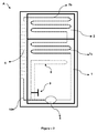
- An exemplary cooler device, subject matter of the invention, is shown in the annexed figures wherein;
-
Figure 1 is a general view of the cooler device. -
Figure 2 is another general view of the cooler device together with the hot fluid tube therein. - In the figures, each part is individually enumerated and corresponding meanings of these reference numbers are given below:
- Cooler device (A)
- Cooling compartment (1)
- Freezing compartment (2)
- Temperature sensor (3)
- Ambient temperature sensor (4)
- Condenser (5)
- Compressor (6)
- Evaporator (7)
- Cooling compartment evaporator (7a)
- Freezing compartment evaporator (7b)
- Heating tube (8)
- Valve (9)
- Compressor output tube (10)
- The cooler device (A) of the invention, used in the storage of food products, has the feature of adjusting the temperature of more than one compartment (1, 2) with a single cooling system. The device (A),of the invention, which especially has at least one cooling and one freezing (1, 2) compartment, operates in a manner that temperature of the freezing compartment (2) is lower than the temperature of the cooling compartment (1). There is at least one temperature sensor (3) provided in any location (1) within the cooling compartment (1), which detects the temperature of the cooling compartment (1) within the device (A). The cooling system of the device (A) is operated until the temperature of the cooling compartment (1) is reduced to the desired level according to the value that the temperature sensor (3) measures by the control unit (although not shown in the figure, regulates the operation of the cooling system of the device (A)) this sensor (3) is linked to; and stops when it reaches to the desired level.
- The cooling system of the device (A) is a cooling system, which comprises units such as compressor (6), condenser (5), and evaporator (7), (and furthermore capillary tube not shown in the figures). The cooling system, operating period and capacity of which are adjusted by the control unit of the device (A), cools both the freezing compartment (2) and the cooling compartment (1) simultaneously. Separate evaporators (7a, 7b) are used for the cooling compartment (1) and freezing compartment (2) in this cooling system, and the said evaporators (7a, 7b) are connected to each other. Put in other words, the evaporator (7) mentioned above comprises two parts (7a, 7b), the refrigerant fluid passing through one evaporator (7a or 7b) passes into the other evaporator (7b or 7a), and returns to the compressor (6) later on and again is prompted to continue with its cooling cycle.
- Under normal circumstances, after the temperature of the cooling compartment (1) is reduced to the desired level, the cooling system stops (according to the value that the temperature sensor (3) in the cooling compartment (1) measures), and thus any further cooling of the freezing compartment (2) also stops. In case the cooling system (A) operates in ambient low temperature on the other hand, the temperature of the cooling compartment (1) may drop to the desired level in a very fast manner. However; under such circumstances it may not be possible to adjust the temperature of the freezing compartment (2) to the desired level. In that case, the operation of the device (A) is regulated again by using at least one external ambient temperature sensor (4), which measures the ambient temperature surrounding the device (A). Accordingly, the control unit enables the heating tube (8) (shown in
Figure 2 , with details given below) to heat the cooling compartment (1) in accordance with the information received from the sensor (4), which measures the external ambient temperature (or by the determination of the operating frequency of the compressor (6) by the control unit, whereby the operating frequency of the compressor decreases in situations where external ambient temperature is low).. Therefore, while delayed cooling of the cooling compartment (1) is ensured, time is saved to reduce the temperature level within the freezing compartment (2) to the desired level. Put in other words, while the cooling of the cooling compartment (1) is delayed with the invention, reducing the temperature to the desired level in the freezing compartment (2) is also ensured. The details of the necessary structure are described inFigure 2 in order for this feature of the device (A) to operate. - As shown in the example in
Figure 2 , there is at least one heating tube (8) linked with at least one interconnecting link to the tube (to the compressor output tube (10)) between the compressor (6) and the condenser (5) in the cooler device (A), which is the subject matter of the invention. The heating tube (8) is designed in a manner allowing it to enter into the cooling compartment (1) of the device (A) or to be in a position to affect temperature of the cooling compartment; the condition for the fluid to pass through this tube (8) is primarily realized if above mentioned external ambient temperature condition is satisfied. Whether the fluid passes through the tube (8) can be adjusted by the heating tube (8) and/or at least one valve (9) (the said valve (9) may be an isolating valve or a directional control valve, the said valve (9) is preferably electrically driven so that it may be operated by the control unit) on the compressor output tube (10). (It becomes possible to directly conduct the fluid coming out of the compressor (6) to the condenser (5) or else to both the heating tube (8) and the condenser (5) by using the valve (9) on the compressor output tube (10) and/or on the heating tube (8). Furthermore, the operation of the valve (9) is regulated according to the temperature values measured by the sensors (3, 4)). - In case of low external ambient temperature that is determined by external ambient temperature sensor (4) and control unit, as mentioned above, the fluid that comes out of the compressor (6) is redirected (via the compressor output tube (10)) towards both heating tube (8) and the condenser (5) simultaneously by means of the said valve (9). Under normal operating conditions, on the other hand, the valve (9) conducts the fluid directly to the condenser (5). Due to the temperature of the fluid coming out of the compressor (6) being higher than the internal temperature of the cooling compartment (1), the fluid that enters the heating tube (8) exchanges heat with the cooling compartment (1) and ensures that the cooling of the compartment (1) is delayed. Meanwhile, as the cooling cycle continues, the fluid exits the condenser (5) (afterwards passing through the capillary tube that is not shown in the figures) and comes to the freezing compartment evaporator (7b). Here, the cooling of the freezing compartment (2) by the freezing compartment evaporator (7b) continues. The fluid that leaves this evaporator (7b) comes to the cooling compartment evaporator (7a). If the fluid passes through the heating tube (8), as mentioned, the cooling of this compartment (1) is delayed. The fluid that comes out of the heating tube (8) returns to the compressor output tube (10) and combines with the fluid leaving the compressor (6) and is transmitted to the condenser (5). The amount of the fluid reaching to the heating tube (8) may be adjusted according to external ambient temperature and temperature of cooling compartment (1). To this end, the desired amount of fluid passage can be ensured through the heating tube (8) and the compressor output tube (10) by means of the a flow rate adjustable valve (9) or else by using at least one flow rate adjuster device on at least one tube (8, 10).
- By taking into consideration the value measured by the external ambient temperature sensor (4) or the operating frequency of the compressor (6) (the compressor (6) operates less frequently under low ambient temperatures), the heating tube (8) is activated or deactivated by the valve (9) that is linked to the control unit. When desired, it is also possible to make the operation of the heating tube (8) (the fluid redirection feature of the valve (8)) optional by allowing the user to select such an option from the control unit (3).
- As an alternative to the exemplary embodiment mentioned above of the invention, the heating of the cooling compartment (1) may be ensured without the use of a valve (9), with at least one heating tube (8) heating the cooling compartment (1) with at least one compressor output tube (10) coming out of the compressor (6) and going into the cooling compartment (1) (or is in a position to affect the temperature of the cooling compartment (1)). In this example at least one heating tube (8) output can be connected to the input of the condenser (5) and/or the compressor (6).
Claims (10)
- A cooler device (A) for food products comprising at least one cooling compartment (1) and one freezing compartment (2); a single cooling system adjusting the temperature of all compartments (1, 2) and comprising a compressor (6), a condenser (5) and freezing compartment evaporator (7b) and cooling compartment evaporator (7a) that are interconnected; at least one temperature sensor (3) measuring the temperature of the cooling compartment (1); at least one temperature sensor (4) measuring the external ambient temperature; a control unit that regulates the operation of the device (A) and is associated with the cooling system and the said sensors (3, 4) and characterized by comprisingat least one heating tube (8) linked to the compressor output tube (10), which is between the compressor (6) and the condenser (5), by at least one interconnection, and which is in such a position that it affects the temperature of the cooling compartment (1); andat least one valve (9), which has the capacity to conduct the fluid that comes out of the compressor (6) directly to the condenser (5) or else to both the heating tube (8) and the condenser (5), and which is placed on the heating tube (8) and/or the compressor output tube (10) and is linked to the control unit.
- A device (A) according to Claim 1, characterized in that the said valve (9) conducts the fluid that comes out of the compressor (6) directly to the condenser (5) under normal operation conditions.
- A device (A) according to Claim 1 characterized in that the valve (9) conducts the fluid that comes out of the compressor (6) to both the heating tube (8) and the condenser (5) in case of a low ambient temperature condition.
- A device (A) according to Claim 1, characterized in that the control unit adjusts the functioning of the valve (9) by considering the value that external ambient temperature sensor (4) measures, or the operating frequency of the compressor (6).
- A device (A) according to Claim 1, characterized in that redirection feature of the valve (9) is selectable via the control unit.
- A device (A) according to Claim 1 characterized in that the valve (9) is an isolating valve.
- A device (A) according to Claim 1, characterized in that the valve (9) is a directional control valve.
- A device (A) according to Claim 1 characterized in that the valve (9) operation is adjusted according to the temperature values measured by the sensors (3, 4).
- A device (A) according to Claim 1, characterized in that the valve (9) is a flow regulating valve.
- A device (A) according to Claim 1, characterized in that at least one flow regulating device is provided in at least one tube (8, 10).
Applications Claiming Priority (1)
| Application Number | Priority Date | Filing Date | Title |
|---|---|---|---|
| TR201003865 | 2010-05-14 |
Publications (2)
| Publication Number | Publication Date |
|---|---|
| EP2386809A2 true EP2386809A2 (en) | 2011-11-16 |
| EP2386809A3 EP2386809A3 (en) | 2013-10-30 |
Family
ID=44070022
Family Applications (1)
| Application Number | Title | Priority Date | Filing Date |
|---|---|---|---|
| EP11161212.3A Withdrawn EP2386809A3 (en) | 2010-05-14 | 2011-04-05 | A cooler device |
Country Status (1)
| Country | Link |
|---|---|
| EP (1) | EP2386809A3 (en) |
Cited By (1)
| Publication number | Priority date | Publication date | Assignee | Title |
|---|---|---|---|---|
| CN107560277A (en) * | 2017-08-03 | 2018-01-09 | 合肥华凌股份有限公司 | Refrigeration plant |
Citations (1)
| Publication number | Priority date | Publication date | Assignee | Title |
|---|---|---|---|---|
| EP1344998A1 (en) | 2002-03-13 | 2003-09-17 | Electrolux Home Products Corporation N.V. | Single-compressor refrigeration apparatus with improved control of the temperature of two storage compartments |
Family Cites Families (3)
| Publication number | Priority date | Publication date | Assignee | Title |
|---|---|---|---|---|
| US2764875A (en) * | 1955-01-26 | 1956-10-02 | Whirlpool Seeger Corp | Household refrigerators of the two temperature type |
| JP2003166776A (en) * | 2001-11-30 | 2003-06-13 | Mitsubishi Electric Corp | Refrigerator control device |
| SI22068A (en) * | 2005-05-19 | 2006-12-31 | Gorenje Gospodinjski Aparati, D.D. | Control of a fridge-freezer appliance |
-
2011
- 2011-04-05 EP EP11161212.3A patent/EP2386809A3/en not_active Withdrawn
Patent Citations (1)
| Publication number | Priority date | Publication date | Assignee | Title |
|---|---|---|---|---|
| EP1344998A1 (en) | 2002-03-13 | 2003-09-17 | Electrolux Home Products Corporation N.V. | Single-compressor refrigeration apparatus with improved control of the temperature of two storage compartments |
Cited By (1)
| Publication number | Priority date | Publication date | Assignee | Title |
|---|---|---|---|---|
| CN107560277A (en) * | 2017-08-03 | 2018-01-09 | 合肥华凌股份有限公司 | Refrigeration plant |
Also Published As
| Publication number | Publication date |
|---|---|
| EP2386809A3 (en) | 2013-10-30 |
Similar Documents
| Publication | Publication Date | Title |
|---|---|---|
| US9140479B2 (en) | Synchronous temperature rate control and apparatus for refrigeration with reduced energy consumption | |
| US9140478B2 (en) | Synchronous temperature rate control for refrigeration with reduced energy consumption | |
| EP2988077B1 (en) | Systems and methods for operating a refrigeration system | |
| CN101568773B (en) | Cooling furniture comprising at least two thermally separate compartments | |
| US9140477B2 (en) | Synchronous compartment temperature control and apparatus for refrigeration with reduced energy consumption | |
| EP3244145B1 (en) | Cooling device | |
| US20080302112A1 (en) | Refrigerant reheat circuit and charge control | |
| US8020391B2 (en) | Refrigeration device control system | |
| US20130174591A1 (en) | Superheat control for a refrigerant vapor compression system | |
| EP3189288B1 (en) | A method for controlling a variable capacity ejector unit | |
| US20110167852A1 (en) | Air-conditioning refrigerating system | |
| JP6040041B2 (en) | Showcase cooling system | |
| US20110167853A1 (en) | Cooling system | |
| CN105745503B (en) | Single-circuit refrigeration device | |
| KR100739195B1 (en) | Refrigeration cycle in refrigerators with two evaporators for precise temperature control | |
| JP2013190906A (en) | Automatic vending machine | |
| EP2390602A2 (en) | A condenser coil unit for cooler devices | |
| US10215460B2 (en) | Variable expansion device with thermal choking for a refrigeration system | |
| WO2016110481A1 (en) | A cooling device | |
| EP3139115B1 (en) | A cooling device comprising a temperature controlled special compartment | |
| EP3128269A1 (en) | A cooling device with improved refrigeration performance | |
| US11674735B2 (en) | Refrigerator appliance with movable control module | |
| EP2369278A1 (en) | Flap arrangement for cooling devices |
Legal Events
| Date | Code | Title | Description |
|---|---|---|---|
| AK | Designated contracting states |
Kind code of ref document: A2 Designated state(s): AL AT BE BG CH CY CZ DE DK EE ES FI FR GB GR HR HU IE IS IT LI LT LU LV MC MK MT NL NO PL PT RO RS SE SI SK SM TR |
|
| AX | Request for extension of the european patent |
Extension state: BA ME |
|
| PUAI | Public reference made under article 153(3) epc to a published international application that has entered the european phase |
Free format text: ORIGINAL CODE: 0009012 |
|
| PUAL | Search report despatched |
Free format text: ORIGINAL CODE: 0009013 |
|
| AK | Designated contracting states |
Kind code of ref document: A3 Designated state(s): AL AT BE BG CH CY CZ DE DK EE ES FI FR GB GR HR HU IE IS IT LI LT LU LV MC MK MT NL NO PL PT RO RS SE SI SK SM TR |
|
| AX | Request for extension of the european patent |
Extension state: BA ME |
|
| RIC1 | Information provided on ipc code assigned before grant |
Ipc: F25D 29/00 20060101ALI20130926BHEP Ipc: F25B 40/04 20060101AFI20130926BHEP Ipc: F25D 11/02 20060101ALI20130926BHEP Ipc: F25B 41/04 20060101ALN20130926BHEP |
|
| STAA | Information on the status of an ep patent application or granted ep patent |
Free format text: STATUS: THE APPLICATION IS DEEMED TO BE WITHDRAWN |
|
| 18D | Application deemed to be withdrawn |
Effective date: 20131101 |