EP2386737B1 - Abdichtung für ein Fördermodul - Google Patents
Abdichtung für ein Fördermodul Download PDFInfo
- Publication number
- EP2386737B1 EP2386737B1 EP11162775A EP11162775A EP2386737B1 EP 2386737 B1 EP2386737 B1 EP 2386737B1 EP 11162775 A EP11162775 A EP 11162775A EP 11162775 A EP11162775 A EP 11162775A EP 2386737 B1 EP2386737 B1 EP 2386737B1
- Authority
- EP
- European Patent Office
- Prior art keywords
- sealing profile
- storage tank
- tank bottom
- tank according
- connection geometry
- Prior art date
- Legal status (The legal status is an assumption and is not a legal conclusion. Google has not performed a legal analysis and makes no representation as to the accuracy of the status listed.)
- Active
Links
Images


Classifications
-
- F—MECHANICAL ENGINEERING; LIGHTING; HEATING; WEAPONS; BLASTING
- F01—MACHINES OR ENGINES IN GENERAL; ENGINE PLANTS IN GENERAL; STEAM ENGINES
- F01N—GAS-FLOW SILENCERS OR EXHAUST APPARATUS FOR MACHINES OR ENGINES IN GENERAL; GAS-FLOW SILENCERS OR EXHAUST APPARATUS FOR INTERNAL-COMBUSTION ENGINES
- F01N3/00—Exhaust or silencing apparatus having means for purifying, rendering innocuous, or otherwise treating exhaust
- F01N3/08—Exhaust or silencing apparatus having means for purifying, rendering innocuous, or otherwise treating exhaust for rendering innocuous
- F01N3/10—Exhaust or silencing apparatus having means for purifying, rendering innocuous, or otherwise treating exhaust for rendering innocuous by thermal or catalytic conversion of noxious components of exhaust
- F01N3/18—Exhaust or silencing apparatus having means for purifying, rendering innocuous, or otherwise treating exhaust for rendering innocuous by thermal or catalytic conversion of noxious components of exhaust characterised by methods of operation; Control
- F01N3/20—Exhaust or silencing apparatus having means for purifying, rendering innocuous, or otherwise treating exhaust for rendering innocuous by thermal or catalytic conversion of noxious components of exhaust characterised by methods of operation; Control specially adapted for catalytic conversion
- F01N3/206—Adding periodically or continuously substances to exhaust gases for promoting purification, e.g. catalytic material in liquid form, NOx reducing agents
- F01N3/2066—Selective catalytic reduction [SCR]
-
- F—MECHANICAL ENGINEERING; LIGHTING; HEATING; WEAPONS; BLASTING
- F01—MACHINES OR ENGINES IN GENERAL; ENGINE PLANTS IN GENERAL; STEAM ENGINES
- F01N—GAS-FLOW SILENCERS OR EXHAUST APPARATUS FOR MACHINES OR ENGINES IN GENERAL; GAS-FLOW SILENCERS OR EXHAUST APPARATUS FOR INTERNAL-COMBUSTION ENGINES
- F01N2610/00—Adding substances to exhaust gases
- F01N2610/14—Arrangements for the supply of substances, e.g. conduits
- F01N2610/1406—Storage means for substances, e.g. tanks or reservoirs
-
- F—MECHANICAL ENGINEERING; LIGHTING; HEATING; WEAPONS; BLASTING
- F01—MACHINES OR ENGINES IN GENERAL; ENGINE PLANTS IN GENERAL; STEAM ENGINES
- F01N—GAS-FLOW SILENCERS OR EXHAUST APPARATUS FOR MACHINES OR ENGINES IN GENERAL; GAS-FLOW SILENCERS OR EXHAUST APPARATUS FOR INTERNAL-COMBUSTION ENGINES
- F01N2610/00—Adding substances to exhaust gases
- F01N2610/14—Arrangements for the supply of substances, e.g. conduits
- F01N2610/1433—Pumps
-
- Y—GENERAL TAGGING OF NEW TECHNOLOGICAL DEVELOPMENTS; GENERAL TAGGING OF CROSS-SECTIONAL TECHNOLOGIES SPANNING OVER SEVERAL SECTIONS OF THE IPC; TECHNICAL SUBJECTS COVERED BY FORMER USPC CROSS-REFERENCE ART COLLECTIONS [XRACs] AND DIGESTS
- Y02—TECHNOLOGIES OR APPLICATIONS FOR MITIGATION OR ADAPTATION AGAINST CLIMATE CHANGE
- Y02T—CLIMATE CHANGE MITIGATION TECHNOLOGIES RELATED TO TRANSPORTATION
- Y02T10/00—Road transport of goods or passengers
- Y02T10/10—Internal combustion engine [ICE] based vehicles
- Y02T10/12—Improving ICE efficiencies
Definitions
- the pollutant nitrogen oxide (NO x ) is to be reduced to an increased extent due to the more stringent exhaust gas legislation to be expected in the next few years.
- a method which is used to reduce the pollutant nitrogen oxide of internal combustion engines the method of selective catalytic reduction (SCR), wherein the pollutant nitric oxide (NO x ) with the aid of a reducing agent, for example, an aqueous urea solution to nitrogen N 2 and water H 2 O is reduced.
- SCR selective catalytic reduction
- the liquid reducing agent is stored in a tank and conveyed by means of a delivery unit such as a pump, via a line from this tank to a metering point.
- a delivery unit for example a pump with which the reducing agent is conveyed to the metering point in the exhaust tract of the internal combustion engine, directly on the tank bottom of the tank receiving the reducing agent and to move the suction point of the delivery unit into the tank bottom.
- a connection geometry of the conveyor module and a suction point, which is formed in the tank bottom, such as a filter with a suction in the tank bottom of the storage tank for receiving the reducing agent.
- a bellows-shaped sealing profile used. With this can be achieved in an advantageous manner that taking place in the axial and radial directions relative movements between the arranged at the bottom of the tank bottom of the storage tank for receiving the reducing agent delivery module and the tank can be compensated.
- the sealing profile is bellows-shaped and has a first bead at one end and a second thickened bead at the other end.
- the first bead may be advantageously clamped within a first compression region in a block of plastic material of the tank bottom.
- the tank bottom is sealed against the delivery module.
- the wall of the sealing profile extends in the axial direction without contact up to a second compression region.
- This second compression region is formed by the second bead formed on the bellows-like sealing profile, which is advantageously formed in a second clamping point between a coupling ring and a connection geometry of the delivery module.
- the inventively proposed sealing profile for sealing the tank bottom against the connection geometry of the conveyor module extends from the already mentioned first compression region and second compression region with a first diameter and a second diameter, wherein between the first diameter and the second diameter of the bellows-shaped sealing profile a transition region consists.
- the second compression region is advantageously formed by a coupling ring, which urges the second bead on the lateral surface of the bellows-shaped sealing profile against a lateral surface of the connection geometry of the conveyor module.
- this coupling ring is provided with a securing spring, which ensures that the coupling ring is captively held at the connection geometry of the conveyor module, forming the second compression region between the second bead of the bellows-shaped sealing profile and the lateral surface of the connection geometry.
- the inventively proposed solution ensures that a decoupling of the components tank bottom and connection geometry of the conveyor module is achieved, which forms a free space due to the circulation gap between the material of the tank bottom and the connection geometry, which compensates for axial and radial relative movements between the tank bottom and the Connection geometry of the constructivemodules can be exploited.
- the proposed solution according to the invention advantageously allows a transmission of movements, such as vibrations, .Exit and shocks of the storage tank to the delivery module, which is attached to the underside on the outside of the storage tank for receiving the reducing agent supply.
- movements such as vibrations, .Exit and shocks of the storage tank
- the delivery module which is attached to the underside on the outside of the storage tank for receiving the reducing agent supply.
- the inventively proposed bellows-shaped sealing profile and the suction without an additional line the medium, ie the reducing agent, for example, an aqueous urea solution can suck.
- inventively proposed solution a significantly higher tolerance compensation is given in terms of adjusting manufacturing inaccuracies of the components to be coupled together. Furthermore, the inventively proposed concept of sealing between the tank bottom of the storage tank for receiving the reducing agent and the conveying module conveying this allows a higher tightness due to component shrinkage over the lifetime of the components to be sealed against each other.
- the bellows-shaped sealing profile proposed by the invention is able to compensate radial and axial relative movements between the components to be sealed against each other and at the same time maintain the sealing force against leakage of the reducing agent, for example an aqueous urea solution to the outside.
- the first compression region and the second compression region in the plastic block of the tank bottom or between the connection geometry of the delivery module and the coupling ring are located exactly where the sealing points are located.
- FIG. 1 is an assembly drawing refer to which represents a tank bottom, and a conveyor module in the assembled state.
- a tank bottom 10 of a storage tank for storing an operating auxiliary, such as an aqueous urea solution as a reducing agent for reducing nitrogen oxides in the exhaust gas of the internal combustion engine comprises a tank bottom 10.
- the storage tank including tank bottom 10 is usually produced as a plastic injection molded component.
- An underside of the tank bottom 10 is identified by reference numeral 12.
- the tank bottom 10 as shown in FIG. 1 has a circumferential butt joint 14.
- At the bottom 12 of the tank bottom 10 is a conveyor module 16, which by means of a in FIG. 2 shown in more detail coupling ring on the bottom 12 of the tank bottom is connected thereto.
- the delivery module 16 is very easily accessible.
- the representation according to FIG. 2 is an exploded view of in FIG. 1 in the assembled state shown function group.
- FIG. 2 shows that in the tank bottom 10 on the side facing away from the bottom 12, a filter 20 is installed, in the region of a lance-shaped suction point 18 extends.
- the suction point 18 is located in the bottom of the tank preferably at a formed in the tank bottom 10 on the inside of the plastic block 42.
- a sealing profile 22 has a first circumferential bead 26 and a second circumferential bead 28.
- the sealing profile 22, which as shown in FIG FIG. 2 is formed as a bellows 24, seals the tank bottom 10 against a connection geometry 36 at the top of the conveyor module 16.
- FIG. 2 shows further that the sealing profile 22 in the form of a bellows 24 is associated with a coupling ring 30 which is secured by means of a securing spring 32 with two open spring legs in its installed position.
- the illustration in accordance with FIG. 2 in that the conveying module 16 is supported with a number of setting supports 34 - three in number in the illustrated embodiment - on the underside 12 of the tank bottom 10 of the storage tank for receiving the reducing agent supply.
- FIG. 3 shows a perspective view of the built-in sealing profile in the form of a bellows between a connection geometry of the conveyor module and a metal sleeve in the region of the suction.
- FIG. 3 shows the sealing profile 22 extends in the form of a bellows 24 in the axial direction from the first circumferential bead 26 to the second circumferential bead 28. From the illustration according to FIG. 3 shows that the first circumferential bead 26 of the sealing profile 22 rests in a first recess 44 of a block-shaped elevation 42 on the tank bottom 10.
- a metal sleeve 38 extends at the suction point 18.
- a free flow cross section of the metal sleeve 38 is indicated by reference numeral 40.
- the interior of the metal sleeve 38 extends along an overlapping region along the first circumferential bead 26 into the interior in the form of a bellows 24 formed sealing profile 22nd
- the second circumferential bead 28 of the sealing profile 22 - which is preferably made of a reducing agent resistant plastic with elastic properties - lies within a second recess 46 which on the one hand by the lateral surface of the connection geometry 36 of the conveyor module 16 and on the other hand by the inner contour of the ring formed as a coupling ring 30 is formed.
- FIG. 3 Furthermore, it is apparent that formed as a coupling ring ring 30 is decoupled from the tank bottom, as well as the connection geometry 36 of the conveyor module 16.
- FIG. 4 shows a side view of in FIG. 3 illustrated perspective view of the metal sleeve of the installed sealing profile and the connection geometry of the conveyor module, secured by the ring formed as a coupling ring.
- the first circumferential bead 26 forms with the first recess 44 in the plastic block 42 on the inside of the tank bottom 10, a first compression region 50.
- a second compression region 52 is given by the second circumferential bead 28, which is formed by the ring 30 formed as a coupling ring on a Lateral surface of the connection geometry is made.
- FIG. 4 It is particularly easy to see that below the first compression region 50 of the sealing profile 22 whose outer surface within the circulation gap 48 extends without contact with respect to the receiving opening in the plastic ring 42 of the tank bottom 10.
- the ring 30 formed as a coupling ring - has a circumferential groove for receiving the locking spring 32.
- the securing spring 32 essentially comprises two mutually parallel spring legs, each having a curvature radially inwardly.
- the ring 30 designed as a coupling ring is detachably fixed to the connecting geometry 36 of the conveying module 16.
- the connection or the seal between the sealing profile 22 as shown in FIG. 5 and the Abdichtgeometrie 36 of the conveyor module 36, see illustration according to FIG. 4 can be easily canceled by radially pulling the locking spring 32.
- connection geometry 36 of the conveyor module 16 can easily down from the sealing profile 22, see illustration according to FIG. 2 , Are pulled out, so that a very easy disassembly of the conveyor module 16 is possible.
- Reference numeral 56 denotes a first leg of the securing spring 32
- Reference numeral 58 denotes a second leg of the securing spring 32.
- the two legs 56 and 58 of the securing spring 32 extend substantially parallel to each other in a receiving groove of the locking ring 30 formed as a coupling ring.
- FIG. 6 The representation according to FIG. 6 is shown in enlarged scale dismantling position of the sealing profile.
- FIG. 6 shows that in the assembled state, the sealing profile 22 in bellows 24 seals on the first compression section 50 with respect to the plastic block 42 of the tank bottom 10 and the second compression region 52 with its second circumferential bead 28 a lateral surface 68 of the connection geometry 36 of the conveyor module 16 seals.
- the geometry of the sealing profile 22 can be achieved that the delivery module 16, which has the connection geometry 36, decoupled from the tank bottom 10 can be received, as well as the sealing points with the first compression region 50 in the tank bottom and with the second compression region 52 between the trained as a coupling ring Ring 30 and the connection geometry 36 are.
- the sealing profile 22 designed as a bellows 24 extends with a first diameter 62 in the direction of a transitional region 66.
- the first inner diameter 62 of the sealing profile 22 merges into a second inner diameter 64 that exceeds this .
- the second inner diameter 64 of the sealing profile 22 substantially corresponds to the outer diameter of the lateral surface 68 of the connection geometry 30, which partially into the sealing profile 22 - as in FIG. 6 to see - is inserted.
- FIG. 6 shows the delivery module 36 is coupled to the sealing profile 22 via the connection geometry 26 in the second compression region 52 freely movable with respect to the tank bottom 10 is formed. Furthermore, from the illustration according to FIG. 6 that the sealing profile 22 below the first Verpressungs Suitees 50, ie the compressed in the compressed state first circumferential bead 26 contactless, ie, a circulation gap 48 to the plastic block 42, extending in the axial direction.
- the representation according to FIG. 6 In addition, it can be seen that at the periphery of the connection geometry 36 below the lateral surface 68 is a securing groove, in which the in the exploded view according to FIG. 2 illustrated securing spring 32 and as well the in FIG. 5 illustrated the first spring leg 56 and the second spring leg 58 having securing bracket 32 is added.
- a seal can be achieved, which is durable and occurring relative movements between the components to be sealed against each other, i. the tank bottom 10 and the conveyor module 16 compensated in the axial and radial directions and is even after several thousand temperature changes still in the situation. Furthermore, it can be achieved by the solution proposed according to the invention that a significantly improved tolerance compensation with regard to manufacturing accuracies between the components to be sealed against one another, i. In particular, the connection geometry 36 of the conveyor module 16 on the one hand and on the other hand, the tank bottom 10 is achieved. It should also be mentioned that, in a particularly advantageous manner, the expected tightness due to component shrinkage over the age of the seal, i. the operating time is significantly improved.
- the sealing effect which is achieved by the sealing profile 22 configured as a bellows 24 according to the invention can be influenced by the depth of the first recess 44 in the plastic block 42 and / or the depression 46 which is formed on the inside of the ring 30 formed as a coupling ring.
- the inventively proposed solution is further advantageously a largely tool-free disassembly of the conveyor module 16 from the bottom 12 of the tank bottom 10 of the storage tank possible as soon as the locking spring 32 is pulled and thereby the connection geometry 36 of the conveyor module 16 simply from the lower part of the Bellows 24 trained sealing profiles 22 pull off.
Landscapes
- Chemical & Material Sciences (AREA)
- Engineering & Computer Science (AREA)
- Chemical Kinetics & Catalysis (AREA)
- Health & Medical Sciences (AREA)
- Toxicology (AREA)
- Combustion & Propulsion (AREA)
- Mechanical Engineering (AREA)
- General Engineering & Computer Science (AREA)
- Exhaust Gas After Treatment (AREA)
Description
- Bei Kraftfahrzeugen, die mit Verbrennungskraftmaschinen angetrieben werden, ist aufgrund der in den nächsten Jahren zu erwartenden verschärften Abgasgesetzgebung unter anderem der Schadstoff Stickoxid (NOx) in erhöhtem Maße zu reduzieren. Ein Verfahren, welches zur Reduzierung des Schadstoffes Stickoxid von Verbrennungskraftmaschinen eingesetzt wird, ist das Verfahren der selektiven katalytischen Reduktion (SCR), bei dem der Schadstoff Stickoxid (NOx) unter Zuhilfenahme eines Reduktionsmittels beispielsweise einer wässrigen Hamstofflösung zu Stickstoff N2 und Wasser H2O reduziert wird. Das flüssige Reduktionsmittel wird in einem Tank gelagert und mittels eines Förderaggregats wie zum Beispiel einer Pumpe, über eine Leitung von diesem Tank zu einer Dosierstelle gefördert.
- Derartige Reduktionssysteme haben bereits Serienreife erreicht und werden in Serie gefertigt und in Kraftfahrzeugen verbaut.
- Aus der
EP1925354 ist es bekannt, einen Reduktionsmitteltank mit einem Förderaggregat zu versehen, das beispielsweise seitlich am Tank angeordnet sein kann. - Erfindungsgemäß wird vorgeschlagen, ein Förderaggregat, so zum Beispiel eine Pumpe, mit welcher das Reduktionsmittel zur Eindosierungsstelle im Abgastrakt der Verbrennungskraftmaschine gefördert wird, direkt am Tankboden des das Reduktionsmittel aufnehmenden Tanks anzuordnen und die Ansaugstelle des Förderaggregats in den Tankboden zu verlegen.
- Dies fordert eine axiale und radiale Relativbewegung kompensierende Abdichtung zwischen einer Anschlussgeometrie des Fördermodules und einer Ansaugstelle, die im Tankboden ausgebildet ist, so zum Beispiel einem Filter mit einer Ansaugstelle im Tankboden des Vorratstankes zur Aufnahme des Reduktionsmittels. Der erfindungsgemäß vorgeschlagenen Lösung folgend, wird zur Abdichtung des Vorrattankes und des Fördermoduls gegeneinander, ein balgartig ausgebildetes Dichtungsprofil eingesetzt. Mit diesem kann in vorteilhafter Weise erreicht werden, dass in axial und radiale Richtung erfolgende Relativbewegungen zwischen dem an der Unterseite des Tankbodens des Vorratstanks zur Aufnahme des Reduktionsmittels angeordneten Fördermodul und dem Tank kompensiert werden können. In vorteilhafter Weise ist das Dichtprofil balgartig ausgebildet und weist an einem Ende einen ersten Wulst und an dem anderen Ende einen zweiten verdickten Wulst auf. Der erste Wulst kann zum Beispiel in vorteilhafter Weise innerhalb eines ersten Verpressungsbereiches in einem Block aus Kunststoffmaterial des Tankbodens eingespannt werden. An dieser ersten Einspannstelle des balgartig konfigurierten Dichtungsprofiles erfolgt eine Abdichtung des Tankbodens gegen das Fördermodul. Ausgehend von dieser ersten Einspannstelle bzw. diesem ersten Verpressungsbereich zwischen dem Dichtprofil in Balgform und dem Tankboden, erstreckt sich die Wand des Dichtprofiles in axiale Richtung kontaktlos bis zu einem zweiten Verpressungsbereich. Dieser zweite Verpressungsbereich ist durch den am balgartig ausgebildeten Dichtprofil ausgebildeten zweiten Wulst gebildet, der in vorteilhafte Weise in einer zweiten Einspannstelle zwischen einem Überwurfring und einer Anschlussgeometrie des Fördermoduls ausgebildet ist.
- Das erfindungsgemäß vorgeschlagene Dichtprofil, zur Abdichtung des Tankbodens gegen die Anschlussgeometrie des Fördermoduls erstreckt sich ausgehend von dem bereits erwähnten ersten Verpressungsbereich und zweiten Verpressungsbereich mit einem ersten Durchmesser und einem zweiten Durchmesser, wobei zwischen dem ersten Durchmesser und dem zweiten Durchmesser des balgartig ausgebildeten Dichtprofiles ein Übergangsbereich besteht. Der zweite Verpressungsbereich wird in vorteilhafter Weise durch einen Überwurfring gebildet, welcher den zweiten Wulst an der Mantelfläche des balgartig ausgebildeten Dichtprofiles gegen eine Mantelfläche der Anschlussgeometrie des Fördermodules drängt. In vorteilhafter Weise ist dieser Überwurfring mit einer Sicherungsfeder versehen, durch welche sichergestellt ist, dass der Überwurfring verliersicher an der Anschlussgeometrie des Fördermoduls, dem zweiten Verpressungsbereich zwischen dem zweiten Wulst des balgartig ausgebildeten Dichtprofiles und der Mantelfläche der Anschlussgeometrie bildend, gehalten ist. Durch die erfindungsgemäß vorgeschlagene Lösung wird erreicht, dass eine Abkopplung der Bauteile Tankboden und Anschlussgeometrie des Fördermodules erreicht wird, wodurch sich aufgrund des Umlaufspaltes zwischen dem Material des Tankbodens und der Anschlussgeometrie ein Freiraum bildet, der zur Kompensation axialer und radialer Relativbewegungen zwischen dem Tankboden und der Anschlussgeometrie des Fördermodules ausgenutzt werden kann. Die erfindungsgemäß vorgeschlagene Lösung erlaubt in vorteilhafter Weise eine Übertragung von Bewegungen, so zum Beispiel bei Schwingungen, .Eisgang und bei Stößen des Vorratstankes an das Fördermodul, welches an der Unterseite auf der Außenseite des Vorratstanks zur Aufnahme des Reduktionsmittelvorrates befestigt ist. Gleichzeitig ist sichergestellt, dass durch das erfindungsgemäß vorgeschlagene balgartig ausgebildete Dichtprofil der Vorratstank gegen das Fördermodul abgedichtet ist und die Ansaugstelle ohne eine zusätzliche Leitung das Medium, d.h. das Reduktionsmittel, so zum Beispiel eine wässrige Harnstofflösung ansaugen kann.
- Durch die erfindungsgemäß vorgeschlagene Lösung ist ein deutlich höherer Toleranzausgleich hinsichtlich sich einstellender Fertigungsungenauigkeiten der miteinander zu koppelnden Bauteile gegeben. Des Weiteren erlaubt das erfindungsgemäß vorgeschlagene Konzept der Abdichtung zwischen dem Tankboden des Vorratstanks zur Aufnahme des Reduktionsmittels und dem dieses fördernden Fördermodul eine höhere Dichtheit aufgrund von Bauteilschrumpfungen über die Lebenszeit der gegeneinander abzudichtenden Komponenten gesehen.
- Durch das erfindungsgemäß vorgeschlagene Dichtprofil in Balgform mit einem ersten umlaufenden Wulst und einem diesen gegenüberliegenden zweiten umlaufenden Wulst, ist eine Entkopplung der gegeneinander abzudichtenden Bauteile - im vorliegenden Anwendungsfall des Tankbodens des Vorratstanks gegen die Anschlussgeometrie des Fördermoduls - sichergestellt. Es wird keine starre Verbindung ausgebildet, die Verpressung, d.h. der erste Verpressungsbereich, der zweite Verpressungsbereich zwischen dem in Balgform ausgebildeten Dichtprofil und dem Tankboden bzw. der Anschlussgeometrie liegen voneinander entfernt. Zwischen dem ersten Verpressungsbereich und dem zweiten Verpressungsbereich vermag das erfindungsgemäß vorgeschlagene in Balgform ausgebildete Dichtprofil, radiale und axiale Relativbewegungen zwischen den gegeneinander abzudichtenden Komponenten auszugleichen und gleichzeitig die Dichtkraft gegen Austritt des Reduktionsmittels, so zum Beispiel eine wässrige Harnstofflösung nach außen, aufrechtzuerhalten. Der erste Verpressungsbereich und der zweite Verpressungsbereich im Kunststoffblock des Tankbodens bzw. zwischen der Anschlussgeometrie des Fördermoduls und dem Überwurfring liegen genau dort, wo die Abdichtstellen lokalisiert sind.
- Durch das erfindungsgemäß vorgeschlagene Dichtprofil in Form eines Balges gelingt es, möglichen axialen Versatz der Ansaugstelle des Fördermodules zur Tanköffnung bei der Montage der Komponenten zu kompensieren. Dadurch lassen sich die Fertigungsgenauigkeiten, die bei der Herstellung der miteinander zu fügenden Komponenten erforderlich sind, reduzieren, was die Herstellungskosten wiederum günstig beeinflusst.
- Kurze Beschreibung der Zeichnungen
- Figur 1
- eine montierte Baugruppe aus Tankboden des Vorratstanks und an dessen Unterseite vorgesehenen Fördermodul,
- Figur 2
- eine Explosionszeichnung der miteinander gefügten Komponenten Filter mit Ansaugstelle, Tankboden, Dichtung, Überwurfring, Sicherungsfeder und Fördermodul,
- Figur 3
- das balgartig ausgebildete Dichtprofil eingespannt zwischen einer Metallhülse im Bereich der Ansaugstelle und der Anschlussgeometrie des Fördermoduls,
- Figur 4
- eine Seitenansicht der in
Figur 3 dargestellten Abdichtstelle zwischen dem Tankboden des Vorratstanks und der Anschlussgeometrie des Fördermoduls, - Figur 5
- eine perspektivische Ansicht des konfigurierten Ringes mit Sicherungsfeder und
- Figur 6
- eine vergrößerte Darstellung des Dichtelementes im eingespannten Zustand zwischen einem Kunststoffblock im Tankboden und der Mantelfläche der Anschlussgeometrie des Fördermoduls.
- Der Darstellung gemäß
Figur 1 ist eine Zusammenstellungszeichnung zu entnehmen, welche einen Tankboden, sowie ein Fördermodul im montierten Zustand darstellt. Ein Tankboden 10 eines Vorratstanks zur Bevorratung eines Betriebshilfsstoffes, wie zum Beispiel einer wässrigen Harnstofflösung als Reduktionsmittel zur Reduzierung von Stickoxiden im Abgas der Verbrennungskraftmaschine umfasst einen Tankboden 10. Der Vorratstank samt Tankboden 10 wird in der Regel als Kunststoffspritzgussbauteil hergestellt. Eine Unterseite des Tankbodens 10 ist durch Bezugszeichen 12 identifiziert. Der Tankboden 10 gemäß der Darstellung inFigur 1 weist eine umlaufende Stoß- bzw. Trennfuge 14 auf. An der Unterseite 12 des Tankbodens 10 befindet sich ein Fördermodul 16, welches mittels eines inFigur 2 detaillierter dargestellten Überwurfringes an der Unterseite 12 des Tankbodens mit diesem verbunden ist. - Durch die Montage des Fördermoduls 16 an der Unterseite 12 des Tankbodens 10 des Vorratstanks zur Aufnahme des Betriebs-Hilfsstoffes ist das Fördermodul 16 sehr leicht zugänglich.
- Der Darstellung gemäß
Figur 2 ist eine Explosionsdarstellung der inFigur 1 in zusammengebautem Zustand dargestellten Funktionsgruppe zu entnehmen. - Aus der Darstellung gemäß
Figur 2 geht hervor, dass in den Tankboden 10 auf der der Unterseite 12 abgewandten Seite ein Filter 20 eingebaut wird, in dessen Bereich eine lanzenförmige Ansaugstelle 18 verläuft. Die Ansaugstelle 18 liegt im Tankboden bevorzugt an einer im Tankboden 10 auf dessen Innenseite ausgebildeten Kunststoffblockes 42. Aus der Explosionsdarstellung gemäßFigur 2 lässt sich des Weiteren entnehmen, dass ein Dichtprofil 22 einen ersten umlaufenden Wulst 26 sowie einen zweiten umlaufenden Wulst 28 aufweist. Das Dichtprofil 22, welches gemäß der Darstellung inFigur 2 als Balg 24 ausgebildet ist, dichtet den Tankboden 10 gegen eine Anschlussgeometrie 36 an der Oberseite des Fördermoduls 16 ab.Figur 2 zeigt des Weiteren, dass dem Dichtprofil 22 in Form eines Balges 24 ein Überwurfring 30 zugeordnet ist, der mittels einer Sicherungsfeder 32 mit zwei offenen Federschenkeln in seiner Einbauposition gesichert ist. Darüber hinaus zeigt die Darstellung gemäßFigur 2 , dass sich das Fördermodul 16 mit einer Anzahl von Anstell-Trägern 34 - im dargestellten Ausführungsbeispiel drei an der Zahl - an der Unterseite 12 des Tankbodens 10 des Vorratstankes zur Aufnahme des Reduktionsmittelvorrates abstützt. -
Figur 3 zeigt eine perspektivische Ansicht des eingebauten Dichtprofiles in Form eines Balges zwischen einer Anschlussgeometrie des Fördermoduls und einer Metallhülse im Bereich der Ansaugstelle. - Wie
Figur 3 zeigt, erstreckt sich das Dichtprofil 22 in Form eines Balges 24 in axiale Richtung vom ersten umlaufenden Wulst 26 zum zweiten umlaufenden Wulst 28. Aus der Darstellung gemäßFigur 3 geht hervor, dass der erste umlaufende Wulst 26 des Dichtprofiles 22 in einer ersten Ausnehmung 44 einer blockförmigen Erhebung 42 am Tankboden 10 anliegt. In den freien Querschnitt des Dichtprofiles 22 erstreckt sich eine Metallhülse 38 an der Ansaugstelle 18. Ein freier Strömungsquerschnitt der Metallhülse 38 ist durch Bezugszeichen 40 gekennzeichnet. Wie aus der Darstellung gemäßFigur 3 hervorgeht, erstreckt sich das Innere der Metallhülse 38 entlang eines Überlappungsbereiches entlang des ersten umlaufenden Wulstes 26 in das Innere in Form eines Balges 24 ausgebildeten Dichtprofiles 22. - An dem dem ersten umlaufenden Wulst 26 gegenüberliegenden Ende des Dichtprofiles 22 in Form eines Balges 24, weist dieses einen zweiten umlaufenden Wulst 28 auf. Der zweite umlaufende Wulst 28 des Dichtprofiles 22 - welches bevorzugt aus einem reduktionsmittelbeständigen Kunststoff mit elastischen Eigenschaften gefertigt wird -, liegt innerhalb einer zweiten Ausnehmung 46, welche einerseits durch die Mantelfläche der Anschlussgeometrie 36 des Fördermoduls 16 und andererseits durch die Innenkontur des als Überwurfring ausgebildeten Ringes 30 gebildet wird. Wie aus der Darstellung gemäß
Figur 3 des Weiteren hervorgeht, ist der als Überwurfring ausgebildete Ring 30 vom Tankboden entkoppelt, ebenso wie die Anschlussgeometrie 36 des Fördermoduls 16. Dadurch ergibt sich in vorteilhafter Weise, dass der Tankboden 10 des den Betriebshilfsstoff aufnehmenden Tanks und die Anschlussgeometrie 36 des Fördermoduls 16 nur durch das axiale und radiale Relativbewegungen ausgleichende Dichtprofil verbunden sind. Wie inFigur 3 angedeutet, erstreckt sich im Bereich der blockförmigen Erhebung 42 auf der Innenseite des Tankbodens 10 entlang der Mantelfläche des Dichtprofiles 22 ein umlaufender Spalt 48. Dies bedeutet, dass sich lediglich ein Teil des als Balg 24 ausgebildeten Dichtprofiles 22 unterhalb des ersten umlaufenden Wulstes 26 in Kontakt mit dem Kunststoffblock 42 am Tankboden 10 befindet, während ab einer Durchmesserverbreiterung in axiale Richtung des Dichtprofiles 22 gesehen, dieses durch den Umlaufspalt 48 getrennt vom Tankboden 10 ist. Der Strömungsquerschnitt 40, die Metallhülse 38 und der Strömungsquerschnitt der Anschlussgeometrie 36 des Fördermoduls 16 entsprechen im Wesentlichen einander. - Durch die axiale Länge des Dichtprofiles 22 zwischen dem ersten umlaufenden Wulst 26 sowie dem zweiten umlaufenden Wulst 28 an den beiden Enden des Dichtprofiles ergibt sich das Maß, um welches der als Überwurfring ausgebildete Dichtring 30 von der Unterseite 12 des Tankbodens 10 entfernt angeordnet ist.
-
Figur 4 zeigt eine Seitenansicht der inFigur 3 dargestellten perspektivischen Wiedergabe der Metallhülse des verbauten Dichtprofiles sowie der Anschlussgeometrie des Fördermoduls, gesichert durch den als Überwurfring ausgebildeten Ring. - Wie
Figur 4 zeigt, bildet der erste umlaufende Wulst 26 mit der ersten Ausnehmung 44 im Kunststoffblock 42 an der Innenseite des Tankbodens 10 einen ersten Verpressungsbereich 50. Ein zweiter Verpressungsbereich 52 ist durch den zweiten umlaufenden Wulst 28 gegeben, der durch den als Überwurfring ausgebildeten Ring 30 an eine Mantelfläche der Anschlussgeometrie angestellt wird. AusFigur 4 ist besonders gut zu erkennen, dass unterhalb des ersten Verpressungsbereiches 50 des Dichtprofiles 22 dessen Außenfläche innerhalb des Umlaufspalts 48 kontaktfrei in Bezug auf die Aufnahmeöffnung im Kunststoffring 42 des Tankbodens 10 verläuft. - Der erste Verpressungsbereich 50 bzw. der zweite Verpressungsbereich 52, mit welchen das Dichtprofil 22 einerseits im Tankboden 10 und andererseits an der Anschlussgeometrie 36 des Fördermoduls 16 abgedichtet ist, liegen dort, wo auch Dichtbereiche liegen. Aus der Darstellung des montierten Zustandes des Dichtprofiles gemäß
Figur 4 geht hervor, dass das Dichtprofil 22, ausgebildet als Balg 24, große Relativbewegungen in radiale und axiale Richtung auszugleichen vermag, was nicht zuletzt seiner Geometrie und seinen elastischen Eigenschaften geschuldet ist. - Der Darstellung gemäß
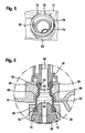
Figur 5 ist zu entnehmen, dass der Ring 30 als Überwurfring ausgebildet - eine umlaufende Nut zur Aufnahme der Sicherungsfeder 32 aufweist. Die Sicherungsfeder 32 umfasst im Wesentlichen zwei sich parallel zueinander erstreckende Federschenkel, die jeweils eine Krümmung radial nach innen aufweisen. Nach Einschieben der Sicherungsfeder ist der als Überwurfring ausgebildete Ring 30 an der Anschlussgeometrie 36 des Fördermoduls 16 lösbar fixiert. Die Verbindung bzw. die Abdichtung zwischen dem Dichtprofil 22 gemäß der Darstellung inFigur 5 und der Abdichtgeometrie 36 des Fördermoduls 36, vergleiche Darstellung gemäßFigur 4 , kann durch radiales Ziehen der Sicherungsfeder 32 einfach aufgehoben werden. Nach Ziehen der Sicherungsfeder 32 kann die Anschlussgeometrie 36 des Fördermoduls 16 einfach nach unten aus dem Dichtprofil 22, vergleiche Darstellung gemäßFigur 2 , herausgezogen werden, so dass eine sehr leichte Demontage des Fördermoduls 16 möglich ist. Mit Bezugszeichen 56 ist ein erster Schenkel der Sicherungsfeder 32 bezeichnet, während Bezugszeichen 58 einen zweiten Schenkel der Sicherungsfeder 32 bezeichnet. Die beiden Schenkel 56 bzw. 58 der Sicherungsfeder 32 erstrecken sich im Wesentlichen parallel zueinander in einer Aufnahmenut des als Überwurfring ausgebildeten Sicherungsrings 30. - Der Darstellung gemäß
Figur 6 ist eine in vergrößertem Maßstab wiedergegebene Demontageposition des Dichtprofiles zu entnehmen. -
Figur 6 zeigt, dass in montiertem Zustand das Dichtprofil 22 in Balgform 24 an dem ersten Verpressungsabschnitt 50 in Bezug auf den Kunststoffblock 42 des Tankbodens 10 dichtet und am zweiten Verpressungsbereich 52 mit seinem zweiten umlaufenden Wulst 28 eine Mantelfläche 68 der Anschlussgeometrie 36 des Fördermoduls 16 abdichtet. Durch die Geometrie des Dichtprofiles 22 kann erreicht werden, dass das Fördermodul 16, welches die Anschlussgeometrie 36 aufweist, entkoppelt vom Tankboden 10 aufgenommen werden kann, sowie die Dichtstellen mit dem ersten Verpressungsbereich 50 im Tankboden und mit dem zweiten Verpressungsbereich 52 zwischen dem als Überwurfring ausgebildeten Ring 30 und der Anschlussgeometrie 36 liegen. WieFigur 6 des Weiteren zeigt, erstreckt sich unterhalb des ersten Verpressungsbereiches 50 das als Balg 24 ausgebildete Dichtprofil 22 mit einem ersten Durchmesser 62 in Richtung auf einen Übergangsbereich 66. Innerhalb des Übergangsbereiches 66 geht der erste Innendurchmesser 62 des Dichtprofiles 22 in einen diesen übersteigenden zweiten Innendurchmesser 64 über. Der zweiten Innendurchmesser 64 des Dichtprofiles 22 entspricht im Wesentlichen dem Außendurchmesser der Mantelfläche 68 der Anschlussgeometrie 30, die teilweise in das Dichtprofil 22 - wie inFigur 6 zu ersehen - eingesteckt ist. Gleiches gilt für ein teilweises Hineinragen eines Anschlusses der Metallhülse 38 in das Dichtprofil im Bereich seines ersten umlaufenden Wulstes 26. - Wie
Figur 6 zeigt, ist das Fördermodul 36 gekoppelt mit dem Dichtprofil 22 über die Anschlussgeometrie 26 in den zweiten Verpressungsbereich 52 frei beweglich in Bezug auf den Tankboden 10 ausgebildet. Des Weiteren geht aus der Darstellung gemäßFigur 6 hervor, dass das Dichtprofil 22 unterhalb des ersten Verpressungsbereiches 50, d.h. dem im verpressten Zustand komprimierten ersten umlaufenden Wulst 26 kontaktlos, d.h. einen Umlaufspalt 48 zum Kunststoffblock 42 aufweisend, sich in axiale Richtung erstreckt. Der Darstellung gemäßFigur 6 ist darüber hinaus zu entnehmen, dass sich am Umfang der Anschlussgeometrie 36 unterhalb der Mantelfläche 68 eine Sicherungsnut befindet, in die der in der Explosionsdarstellung gemäßFigur 2 dargestellte Sicherungsfeder 32 und sowie der inFigur 5 dargestellte den ersten Federschenkel 56 und den zweiten Federschenkel 58 aufweisende Sicherungsbügel 32 aufgenommen ist. - Durch die erfindungsgemäß vorgeschlagene Abdichtung zwischen dem Tankboden 10 des den Betriebshilfsstoff aufnehmenden Vorratstanks und dem Fördermodul 16, kann eine Abdichtung erreicht werden, die dauerfest ist und auftretende Relativbewegungen zwischen den gegeneinander abzudichtenden Bauteilen, d.h. dem Tankboden 10 und dem Fördermodul 16 in axiale und radiale Richtung kompensiert und dazu auch nach etlichen tausend Temperaturwechseln noch in der Lage ist. Des Weiteren kann durch die erfindungsgemäß vorgeschlagene Lösung erreicht werden, dass ein deutlich verbesserter Toleranzausgleich hinsichtlich Fertigungsgenauigkeiten zwischen den gegeneinander abzudichtenden Komponenten, d.h. insbesondere der Anschlussgeometrie 36 des Fördermoduls 16 auf der einen Seite und andererseits den Tankboden 10 erreicht wird. Des Weiteren ist zu erwähnen, dass in besonders vorteilhafter Weise die zu erwartende Dichtheit aufgrund von Bauteilschrumpfungen über das Alter der Abdichtung, d.h. die Betriebszeit gesehen, deutlich verbessert ist.
- Die Abdichtwirkung, die durch das erfindungsgemäß vorgeschlagene als Balg 24 konfigurierte Dichtprofil 22 erreicht wird, kann durch die Tiefe der ersten Ausnehmung 44 im Kunststoffblock 42 und/oder die Vertiefung 46 beeinflusst werden, die an der Innenseite des als Überwurfring ausgebildeten Rings 30 ausgebildet ist. Entsprechendes gilt für die Dicke der umlaufenden Wülste 26, 28 an den beiden Stirnseiten des als Balg 24 ausgebildeten Dichtprofiles 22. Werden die umlaufenden Wülste 26, 28 hinsichtlich ihrer Dicke unterschiedlich dimensioniert, so lassen sich unterschiedlich hohe Verpressungen innerhalb des Verpressungsbereiches 50 sowie des zweiten Verpressungsbereiches 52 einstellen und dauerhaft aufrechterhalten.
- Durch die erfindungsgemäß vorgeschlagene Lösung ist des Weiteren in vorteilhafter Weise eine weitestgehend werkzeuglose Demontage des Fördermoduls 16 von der Unterseite 12 des Tankbodens 10 des Vorratstanks möglich, sobald die Sicherungsfeder 32 gezogen wird und sich dadurch die Anschlussgeometrie 36 des Fördermoduls 16 einfach vom unteren Bereich des als Balg 24 ausgebildeten Dichtprofiles 22 abziehen lässt.
Claims (10)
- Vorratstank zur Aufnahme eines Betriebshilfsstoffes, insbesondere eines Reduktionsmittels für eine Brennkraftmaschine, mit einem Tankboden (10) und einem Fördermodul (16), dadurch gekennzeichnet, dass der Tankboden (10) und das Fördermodul (16) durch ein balgartiges, radiale und axiale Relativbewegungen zwischen Tankboden (10) und dem Fördermodul (16) ausgleichendes Dichtprofil (22, 24) abgedichtet sind.
- Vorratstank gemäß Anspruch 1, dadurch gekennzeichnet, dass das Dichtprofil (22, 24) einen ersten umlaufenden Wulst (26) sowie einen zweiten umlaufenden Wulst (28) aufweist.
- Vorratstank gemäß einem der vorhergehenden Ansprüche, dadurch gekennzeichnet, dass das Dichtprofil (22, 24) am ersten umlaufenden Wulst (26) in einer ersten Ausnehmung (44) eines Kunststoffblocks (42) des Tankbodens (10) in einem ersten Verpressungsbereich (50) eingespannt ist.
- Vorratstank gemäß des vorhergehenden Anspruchs, dadurch gekennzeichnet, dass sich das Dichtprofil (22, 24) vom ersten Verpressungsbereich (50) ausgehend, in einem Umlaufspalt (48) kontaktlos zu einem Ring (30) erstreckt, der eine Anschlussgeometrie (36) des Fördermodules (16) umschließt.
- Vorratstank gemäß einem der vorhergehenden Ansprüche, dadurch gekennzeichnet, dass der zweite umlaufende Wulst (28) des Dichtprofiles (22) zwischen dem Ring (30) und der Anschlussgeometrie (36) in einem zweiten Verpressungsbereich (52) eingespannt ist.
- Vorratstank gemäß einem der vorhergehenden Ansprüche, dadurch gekennzeichnet, dass sich das Dichtprofil (22, 24) zwischen den Verpressungsbereichen (50, 52) im Umlaufspalt (48) erstreckt.
- Vorratstank gemäß einem der vorhergehenden Ansprüche, dadurch gekennzeichnet, dass der Ring (30) eine Sicherungsfeder (32) aufnimmt.
- Vorratstank gemäß einem der vorhergehenden Ansprüche, dadurch gekennzeichnet, dass das Dichtprofil (22, 24) einen Bereich in einem ersten Durchmesser (62) aufweist sowie einen Bereich, der in einem zweiten Durchmesser (64) ausgebildet ist.
- Vorratstank gemäß einem der vorhergehenden Ansprüche, dadurch gekennzeichnet, dass der erste Durchmesser (62) des Dichtprofiles (22, 24) dem Durchmesser einer Metallhülse (38) an einer Umlaufnut (60) entspricht.
- Vorratstank gemäß einem der vorhergehenden Ansprüche, dadurch gekennzeichnet, dass der zweite Durchmesser (64) des Dichtprofiles (22, 24) dem Durchmesser einer Mantelfläche (68) der Anschlussgeometrie (36) des Fördermoduls (16) entspricht.
Applications Claiming Priority (1)
| Application Number | Priority Date | Filing Date | Title |
|---|---|---|---|
| DE102010028908A DE102010028908A1 (de) | 2010-05-12 | 2010-05-12 | Abdichtung für ein Fördermodul |
Publications (2)
| Publication Number | Publication Date |
|---|---|
| EP2386737A1 EP2386737A1 (de) | 2011-11-16 |
| EP2386737B1 true EP2386737B1 (de) | 2012-12-05 |
Family
ID=44350612
Family Applications (1)
| Application Number | Title | Priority Date | Filing Date |
|---|---|---|---|
| EP11162775A Active EP2386737B1 (de) | 2010-05-12 | 2011-04-18 | Abdichtung für ein Fördermodul |
Country Status (2)
| Country | Link |
|---|---|
| EP (1) | EP2386737B1 (de) |
| DE (1) | DE102010028908A1 (de) |
Family Cites Families (2)
| Publication number | Priority date | Publication date | Assignee | Title |
|---|---|---|---|---|
| WO2007141312A1 (en) * | 2006-06-08 | 2007-12-13 | Inergy Automotive Systems Research (Société Anonyme) | Engine exhaust gas additive storage system |
| DE102006050807A1 (de) * | 2006-10-27 | 2008-04-30 | Robert Bosch Gmbh | Katalytische Reduktionseinrichtung |
-
2010
- 2010-05-12 DE DE102010028908A patent/DE102010028908A1/de not_active Withdrawn
-
2011
- 2011-04-18 EP EP11162775A patent/EP2386737B1/de active Active
Also Published As
| Publication number | Publication date |
|---|---|
| EP2386737A1 (de) | 2011-11-16 |
| DE102010028908A1 (de) | 2011-11-17 |
Similar Documents
| Publication | Publication Date | Title |
|---|---|---|
| EP2935859B1 (de) | Kolben-kraftstoffpumpe für eine brennkraftmaschine | |
| DE102008027279B4 (de) | Filterelement und Verfahren zur Herstellung eines Filterelements | |
| DE102016203217B4 (de) | Dämpferkapsel, Druckpulsationsdämpfer und Kraftstoffhochdruckpumpe | |
| EP2282825B1 (de) | Filtersystem | |
| EP2794371B1 (de) | Kolbenpumpe für eine fahrzeugbremsanlage | |
| DE102009051286A1 (de) | Ringdichtung mit Einsatz | |
| DE10056405B4 (de) | Kraftstoffhochdruckspeicher für ein Kraftstoffeinspritzsystem für Brennkraftmaschinen | |
| DE102012204845A1 (de) | Halter zur Befestigung einer Komponente an einer Brennkraftmaschine, Lagerbuchse für solch einen Halter und Brennstoffeinspritzanlage | |
| DE3510267A1 (de) | Zuleitungsschlauchsatz zur daempfung von fluiddruckpulsationen | |
| EP2636901B1 (de) | Hochdruckeinrichtung für flüssige Medien | |
| DE102016206949A1 (de) | Verfahren zur Herstellung einer Baueinheit, Vulkanisationswerkzeug und Baueinheit | |
| DE102019217207A1 (de) | Kraftstoff-Hochdruckpumpe für ein Kraftstoffsystem einer Brennkraftmaschine | |
| DE102015215933B4 (de) | Flüssigkeitsfilter | |
| EP2519743B1 (de) | Kolbenpumpe mit einem einlassventil | |
| DE102015202992A1 (de) | Niederdruck-Anschlusseinheit sowie Hochdruckpumpe mit einer Niederdruck-Anschlusseinheit | |
| EP2249058A2 (de) | Kolben-Zylinder-Aggregat mit einem Anschlussorgan | |
| EP2759437B1 (de) | Vorrichtung zum Befüllen zumindest eines in einem Kraftfahrzeug angeordneten Kraftstofftanks | |
| EP3353410B1 (de) | Druckpulsationsdämpfer für ein kraftstoffeinspritzsystem sowie kraftstoffeinspritzsystem | |
| EP2252795B1 (de) | Brennstoffpumpe | |
| EP2386737A1 (de) | Abdichtung für ein Fördermodul | |
| EP1419001B1 (de) | Gehäuse | |
| DE102014218992A1 (de) | Kraftstoffhochdruckpumpe | |
| EP3356116B1 (de) | Komponente für brennstoffeinspritzanlage und verfahren zum herstellen einer komponente einer brennstoffeinspritzanlage | |
| DE102012108942B4 (de) | Fördereinheit für ein flüssiges Additiv | |
| EP3130791B1 (de) | Baugruppe für einen ansaugtrakt einer brennkraftmaschine |
Legal Events
| Date | Code | Title | Description |
|---|---|---|---|
| AK | Designated contracting states |
Kind code of ref document: A1 Designated state(s): AL AT BE BG CH CY CZ DE DK EE ES FI FR GB GR HR HU IE IS IT LI LT LU LV MC MK MT NL NO PL PT RO RS SE SI SK SM TR |
|
| AX | Request for extension of the european patent |
Extension state: BA ME |
|
| PUAI | Public reference made under article 153(3) epc to a published international application that has entered the european phase |
Free format text: ORIGINAL CODE: 0009012 |
|
| 17P | Request for examination filed |
Effective date: 20120516 |
|
| RIC1 | Information provided on ipc code assigned before grant |
Ipc: F01N 3/20 20060101AFI20120731BHEP |
|
| GRAP | Despatch of communication of intention to grant a patent |
Free format text: ORIGINAL CODE: EPIDOSNIGR1 |
|
| GRAS | Grant fee paid |
Free format text: ORIGINAL CODE: EPIDOSNIGR3 |
|
| GRAA | (expected) grant |
Free format text: ORIGINAL CODE: 0009210 |
|
| AK | Designated contracting states |
Kind code of ref document: B1 Designated state(s): AL AT BE BG CH CY CZ DE DK EE ES FI FR GB GR HR HU IE IS IT LI LT LU LV MC MK MT NL NO PL PT RO RS SE SI SK SM TR |
|
| REG | Reference to a national code |
Ref country code: GB Ref legal event code: FG4D Free format text: NOT ENGLISH |
|
| REG | Reference to a national code |
Ref country code: CH Ref legal event code: EP |
|
| REG | Reference to a national code |
Ref country code: AT Ref legal event code: REF Ref document number: 587418 Country of ref document: AT Kind code of ref document: T Effective date: 20121215 |
|
| REG | Reference to a national code |
Ref country code: IE Ref legal event code: FG4D Free format text: LANGUAGE OF EP DOCUMENT: GERMAN |
|
| REG | Reference to a national code |
Ref country code: DE Ref legal event code: R096 Ref document number: 502011000254 Country of ref document: DE Effective date: 20130131 |
|
| PG25 | Lapsed in a contracting state [announced via postgrant information from national office to epo] |
Ref country code: ES Free format text: LAPSE BECAUSE OF FAILURE TO SUBMIT A TRANSLATION OF THE DESCRIPTION OR TO PAY THE FEE WITHIN THE PRESCRIBED TIME-LIMIT Effective date: 20130316 Ref country code: NO Free format text: LAPSE BECAUSE OF FAILURE TO SUBMIT A TRANSLATION OF THE DESCRIPTION OR TO PAY THE FEE WITHIN THE PRESCRIBED TIME-LIMIT Effective date: 20130305 Ref country code: SE Free format text: LAPSE BECAUSE OF FAILURE TO SUBMIT A TRANSLATION OF THE DESCRIPTION OR TO PAY THE FEE WITHIN THE PRESCRIBED TIME-LIMIT Effective date: 20121205 Ref country code: FI Free format text: LAPSE BECAUSE OF FAILURE TO SUBMIT A TRANSLATION OF THE DESCRIPTION OR TO PAY THE FEE WITHIN THE PRESCRIBED TIME-LIMIT Effective date: 20121205 Ref country code: LT Free format text: LAPSE BECAUSE OF FAILURE TO SUBMIT A TRANSLATION OF THE DESCRIPTION OR TO PAY THE FEE WITHIN THE PRESCRIBED TIME-LIMIT Effective date: 20121205 |
|
| REG | Reference to a national code |
Ref country code: NL Ref legal event code: VDEP Effective date: 20121205 |
|
| REG | Reference to a national code |
Ref country code: LT Ref legal event code: MG4D |
|
| PG25 | Lapsed in a contracting state [announced via postgrant information from national office to epo] |
Ref country code: LV Free format text: LAPSE BECAUSE OF FAILURE TO SUBMIT A TRANSLATION OF THE DESCRIPTION OR TO PAY THE FEE WITHIN THE PRESCRIBED TIME-LIMIT Effective date: 20121205 Ref country code: GR Free format text: LAPSE BECAUSE OF FAILURE TO SUBMIT A TRANSLATION OF THE DESCRIPTION OR TO PAY THE FEE WITHIN THE PRESCRIBED TIME-LIMIT Effective date: 20130306 Ref country code: SI Free format text: LAPSE BECAUSE OF FAILURE TO SUBMIT A TRANSLATION OF THE DESCRIPTION OR TO PAY THE FEE WITHIN THE PRESCRIBED TIME-LIMIT Effective date: 20121205 Ref country code: PL Free format text: LAPSE BECAUSE OF FAILURE TO SUBMIT A TRANSLATION OF THE DESCRIPTION OR TO PAY THE FEE WITHIN THE PRESCRIBED TIME-LIMIT Effective date: 20121205 |
|
| PG25 | Lapsed in a contracting state [announced via postgrant information from national office to epo] |
Ref country code: RS Free format text: LAPSE BECAUSE OF FAILURE TO SUBMIT A TRANSLATION OF THE DESCRIPTION OR TO PAY THE FEE WITHIN THE PRESCRIBED TIME-LIMIT Effective date: 20121205 Ref country code: CZ Free format text: LAPSE BECAUSE OF FAILURE TO SUBMIT A TRANSLATION OF THE DESCRIPTION OR TO PAY THE FEE WITHIN THE PRESCRIBED TIME-LIMIT Effective date: 20121205 Ref country code: SK Free format text: LAPSE BECAUSE OF FAILURE TO SUBMIT A TRANSLATION OF THE DESCRIPTION OR TO PAY THE FEE WITHIN THE PRESCRIBED TIME-LIMIT Effective date: 20121205 Ref country code: EE Free format text: LAPSE BECAUSE OF FAILURE TO SUBMIT A TRANSLATION OF THE DESCRIPTION OR TO PAY THE FEE WITHIN THE PRESCRIBED TIME-LIMIT Effective date: 20121205 Ref country code: IS Free format text: LAPSE BECAUSE OF FAILURE TO SUBMIT A TRANSLATION OF THE DESCRIPTION OR TO PAY THE FEE WITHIN THE PRESCRIBED TIME-LIMIT Effective date: 20130405 Ref country code: BG Free format text: LAPSE BECAUSE OF FAILURE TO SUBMIT A TRANSLATION OF THE DESCRIPTION OR TO PAY THE FEE WITHIN THE PRESCRIBED TIME-LIMIT Effective date: 20130305 |
|
| PG25 | Lapsed in a contracting state [announced via postgrant information from national office to epo] |
Ref country code: NL Free format text: LAPSE BECAUSE OF FAILURE TO SUBMIT A TRANSLATION OF THE DESCRIPTION OR TO PAY THE FEE WITHIN THE PRESCRIBED TIME-LIMIT Effective date: 20121205 Ref country code: RO Free format text: LAPSE BECAUSE OF FAILURE TO SUBMIT A TRANSLATION OF THE DESCRIPTION OR TO PAY THE FEE WITHIN THE PRESCRIBED TIME-LIMIT Effective date: 20121205 Ref country code: PT Free format text: LAPSE BECAUSE OF FAILURE TO SUBMIT A TRANSLATION OF THE DESCRIPTION OR TO PAY THE FEE WITHIN THE PRESCRIBED TIME-LIMIT Effective date: 20130405 |
|
| PLBE | No opposition filed within time limit |
Free format text: ORIGINAL CODE: 0009261 |
|
| STAA | Information on the status of an ep patent application or granted ep patent |
Free format text: STATUS: NO OPPOSITION FILED WITHIN TIME LIMIT |
|
| BERE | Be: lapsed |
Owner name: ROBERT BOSCH G.M.B.H. Effective date: 20130430 |
|
| PG25 | Lapsed in a contracting state [announced via postgrant information from national office to epo] |
Ref country code: DK Free format text: LAPSE BECAUSE OF FAILURE TO SUBMIT A TRANSLATION OF THE DESCRIPTION OR TO PAY THE FEE WITHIN THE PRESCRIBED TIME-LIMIT Effective date: 20121205 |
|
| 26N | No opposition filed |
Effective date: 20130906 |
|
| PG25 | Lapsed in a contracting state [announced via postgrant information from national office to epo] |
Ref country code: MC Free format text: LAPSE BECAUSE OF FAILURE TO SUBMIT A TRANSLATION OF THE DESCRIPTION OR TO PAY THE FEE WITHIN THE PRESCRIBED TIME-LIMIT Effective date: 20121205 Ref country code: HR Free format text: LAPSE BECAUSE OF FAILURE TO SUBMIT A TRANSLATION OF THE DESCRIPTION OR TO PAY THE FEE WITHIN THE PRESCRIBED TIME-LIMIT Effective date: 20121205 Ref country code: CY Free format text: LAPSE BECAUSE OF FAILURE TO SUBMIT A TRANSLATION OF THE DESCRIPTION OR TO PAY THE FEE WITHIN THE PRESCRIBED TIME-LIMIT Effective date: 20121205 |
|
| PG25 | Lapsed in a contracting state [announced via postgrant information from national office to epo] |
Ref country code: IT Free format text: LAPSE BECAUSE OF FAILURE TO SUBMIT A TRANSLATION OF THE DESCRIPTION OR TO PAY THE FEE WITHIN THE PRESCRIBED TIME-LIMIT Effective date: 20121205 |
|
| REG | Reference to a national code |
Ref country code: DE Ref legal event code: R097 Ref document number: 502011000254 Country of ref document: DE Effective date: 20130906 |
|
| REG | Reference to a national code |
Ref country code: IE Ref legal event code: MM4A |
|
| PG25 | Lapsed in a contracting state [announced via postgrant information from national office to epo] |
Ref country code: BE Free format text: LAPSE BECAUSE OF NON-PAYMENT OF DUE FEES Effective date: 20130430 |
|
| PG25 | Lapsed in a contracting state [announced via postgrant information from national office to epo] |
Ref country code: IE Free format text: LAPSE BECAUSE OF NON-PAYMENT OF DUE FEES Effective date: 20130418 |
|
| REG | Reference to a national code |
Ref country code: CH Ref legal event code: PL |
|
| PG25 | Lapsed in a contracting state [announced via postgrant information from national office to epo] |
Ref country code: LI Free format text: LAPSE BECAUSE OF NON-PAYMENT OF DUE FEES Effective date: 20140430 Ref country code: CH Free format text: LAPSE BECAUSE OF NON-PAYMENT OF DUE FEES Effective date: 20140430 |
|
| PG25 | Lapsed in a contracting state [announced via postgrant information from national office to epo] |
Ref country code: MT Free format text: LAPSE BECAUSE OF FAILURE TO SUBMIT A TRANSLATION OF THE DESCRIPTION OR TO PAY THE FEE WITHIN THE PRESCRIBED TIME-LIMIT Effective date: 20121205 |
|
| PG25 | Lapsed in a contracting state [announced via postgrant information from national office to epo] |
Ref country code: SM Free format text: LAPSE BECAUSE OF FAILURE TO SUBMIT A TRANSLATION OF THE DESCRIPTION OR TO PAY THE FEE WITHIN THE PRESCRIBED TIME-LIMIT Effective date: 20121205 |
|
| PG25 | Lapsed in a contracting state [announced via postgrant information from national office to epo] |
Ref country code: TR Free format text: LAPSE BECAUSE OF FAILURE TO SUBMIT A TRANSLATION OF THE DESCRIPTION OR TO PAY THE FEE WITHIN THE PRESCRIBED TIME-LIMIT Effective date: 20121205 |
|
| PG25 | Lapsed in a contracting state [announced via postgrant information from national office to epo] |
Ref country code: LU Free format text: LAPSE BECAUSE OF NON-PAYMENT OF DUE FEES Effective date: 20130418 Ref country code: HU Free format text: LAPSE BECAUSE OF FAILURE TO SUBMIT A TRANSLATION OF THE DESCRIPTION OR TO PAY THE FEE WITHIN THE PRESCRIBED TIME-LIMIT; INVALID AB INITIO Effective date: 20110418 Ref country code: MK Free format text: LAPSE BECAUSE OF FAILURE TO SUBMIT A TRANSLATION OF THE DESCRIPTION OR TO PAY THE FEE WITHIN THE PRESCRIBED TIME-LIMIT Effective date: 20121205 |
|
| GBPC | Gb: european patent ceased through non-payment of renewal fee |
Effective date: 20150418 |
|
| PG25 | Lapsed in a contracting state [announced via postgrant information from national office to epo] |
Ref country code: GB Free format text: LAPSE BECAUSE OF NON-PAYMENT OF DUE FEES Effective date: 20150418 |
|
| REG | Reference to a national code |
Ref country code: FR Ref legal event code: PLFP Year of fee payment: 6 |
|
| REG | Reference to a national code |
Ref country code: FR Ref legal event code: PLFP Year of fee payment: 7 |
|
| REG | Reference to a national code |
Ref country code: AT Ref legal event code: MM01 Ref document number: 587418 Country of ref document: AT Kind code of ref document: T Effective date: 20160418 |
|
| PG25 | Lapsed in a contracting state [announced via postgrant information from national office to epo] |
Ref country code: AT Free format text: LAPSE BECAUSE OF NON-PAYMENT OF DUE FEES Effective date: 20160418 |
|
| REG | Reference to a national code |
Ref country code: FR Ref legal event code: PLFP Year of fee payment: 8 |
|
| PG25 | Lapsed in a contracting state [announced via postgrant information from national office to epo] |
Ref country code: AL Free format text: LAPSE BECAUSE OF FAILURE TO SUBMIT A TRANSLATION OF THE DESCRIPTION OR TO PAY THE FEE WITHIN THE PRESCRIBED TIME-LIMIT Effective date: 20121205 |
|
| PGFP | Annual fee paid to national office [announced via postgrant information from national office to epo] |
Ref country code: FR Payment date: 20230417 Year of fee payment: 13 |
|
| PG25 | Lapsed in a contracting state [announced via postgrant information from national office to epo] |
Ref country code: FR Free format text: LAPSE BECAUSE OF NON-PAYMENT OF DUE FEES Effective date: 20240430 |
|
| PG25 | Lapsed in a contracting state [announced via postgrant information from national office to epo] |
Ref country code: FR Free format text: LAPSE BECAUSE OF NON-PAYMENT OF DUE FEES Effective date: 20240430 |
|
| PGFP | Annual fee paid to national office [announced via postgrant information from national office to epo] |
Ref country code: DE Payment date: 20250624 Year of fee payment: 15 |