EP2386719B1 - Pressure balancing device - Google Patents
Pressure balancing device Download PDFInfo
- Publication number
- EP2386719B1 EP2386719B1 EP11164922.4A EP11164922A EP2386719B1 EP 2386719 B1 EP2386719 B1 EP 2386719B1 EP 11164922 A EP11164922 A EP 11164922A EP 2386719 B1 EP2386719 B1 EP 2386719B1
- Authority
- EP
- European Patent Office
- Prior art keywords
- pressure
- balancing device
- pressure balancing
- cross
- piston
- Prior art date
- Legal status (The legal status is an assumption and is not a legal conclusion. Google has not performed a legal analysis and makes no representation as to the accuracy of the status listed.)
- Active
Links
Images
Classifications
-
- E—FIXED CONSTRUCTIONS
- E21—EARTH OR ROCK DRILLING; MINING
- E21B—EARTH OR ROCK DRILLING; OBTAINING OIL, GAS, WATER, SOLUBLE OR MELTABLE MATERIALS OR A SLURRY OF MINERALS FROM WELLS
- E21B47/00—Survey of boreholes or wells
- E21B47/01—Devices for supporting measuring instruments on drill bits, pipes, rods or wirelines; Protecting measuring instruments in boreholes against heat, shock, pressure or the like
-
- E—FIXED CONSTRUCTIONS
- E21—EARTH OR ROCK DRILLING; MINING
- E21B—EARTH OR ROCK DRILLING; OBTAINING OIL, GAS, WATER, SOLUBLE OR MELTABLE MATERIALS OR A SLURRY OF MINERALS FROM WELLS
- E21B47/00—Survey of boreholes or wells
- E21B47/007—Measuring stresses in a pipe string or casing
-
- E—FIXED CONSTRUCTIONS
- E21—EARTH OR ROCK DRILLING; MINING
- E21B—EARTH OR ROCK DRILLING; OBTAINING OIL, GAS, WATER, SOLUBLE OR MELTABLE MATERIALS OR A SLURRY OF MINERALS FROM WELLS
- E21B47/00—Survey of boreholes or wells
- E21B47/01—Devices for supporting measuring instruments on drill bits, pipes, rods or wirelines; Protecting measuring instruments in boreholes against heat, shock, pressure or the like
- E21B47/017—Protecting measuring instruments
-
- G—PHYSICS
- G01—MEASURING; TESTING
- G01L—MEASURING FORCE, STRESS, TORQUE, WORK, MECHANICAL POWER, MECHANICAL EFFICIENCY, OR FLUID PRESSURE
- G01L19/00—Details of, or accessories for, apparatus for measuring steady or quasi-steady pressure of a fluent medium insofar as such details or accessories are not special to particular types of pressure gauges
- G01L19/06—Means for preventing overload or deleterious influence of the measured medium on the measuring device or vice versa
- G01L19/0627—Protection against aggressive medium in general
- G01L19/0645—Protection against aggressive medium in general using isolation membranes, specially adapted for protection
Definitions
- the present invention relates to a pressure balancing device, such as for a transducer.
- Downhole logging tools are frequently designed to be pressure balanced. This is where a measurement sensor is located within the body of the tool and is protected from well fluid by appropriate sealed housings, but where some form of pressure transmission device is used to compress a fluid within the tool to approximately the same pressure as the well fluid outside. In this manner, the sensor is exposed to the well pressure, without suffering the consequences of being immersed directly in the well fluid.
- the compensating mechanism must also allow for the internal fluid to expand at low pressure but high temperature.
- Pressure compensating mechanisms regularly used downhole include pistons, rubber bladders and flexible metal bellows. Each mechanism has advantages and disadvantages in terms of the resulting pressure difference between the inside and outside of the tool, such as maintainability, cost, durability and resistance to attack from the chemicals in the well.
- compensating pistons are often used, due to their simple design and rugged construction.
- inherent in the design of a piston compensating system is the need for dynamic sliding seals, which experience high hydrostatic pressures and therefore suffer from high friction, and resist the motion of the piston. This resistance to motion results in a differential pressure across the piston, which corresponds to a minimum force required to move the piston against its seals. The higher the seal friction, the larger the differential pressure will be between the inside and the outside of the tool.
- both the bladder and the flexible metal bellows have stiffness in their structures, which resist motion and hence, generate a differential pressure.
- a typical example of a downhole pressure sensitive device is a cable head load measuring tool. This tool is placed at the top of a logging tool string and is designed to report to the user the force being exerted on the tool string by the wireline or tractoring tool. Essentially, the tool must measure differential axial loading in the string, but not the axial load produced solely by the well pressure surrounding the string. Using a pressure balanced load measuring sensor is one solution, which inherently requires a good pressure compensating device.
- EP 0 098 790 is concerned with a pressure-compensating device in load cells.
- the present invention provides a pressure balancing device for a transducer as defined in claim 1.
- an improved downhole tool pressure balancing method for transducers, which is sensitive to differential pressure between an oil well for example and the tool interior.
- transducers which is sensitive to differential pressure between an oil well for example and the tool interior.
- established pressure balancing mechanisms such as pistons, flexible bellows and rubber bladders
- the area ratio of the compensation device and a shaft passing through a mandrel is carefully controlled so as to reduce the impact of differential pressure created by compensator friction or stiffness on the induced transducer error.
- the hollow shaft may be a load transmission shaft which may be connected to a load sensor.
- the area ratio of the piston and the mandrel around the shaft have a ratio smaller than 1, such as less than 0.8 or less then 0.7, for example rather than equal to 1. This reduces the effect of the compensator/pressure transmission device friction/stiffness on the measured variable.
- the improved pressure balancing configuration allows pressure sensitive transducers to suffer less measurement error than a conventional pressure balancing system.
- the configuration results in increased accuracy and reduced hysteresis due to pressure changes over a system using a conventional pressure compensator.
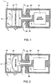
- the pressure balancing device 1 of this example has a pressure transmission device 10, which in this example is a piston, provided in a housing 20.
- the pressure transmission device 10 could for example be a rubber bladder or a flexible metal bellows.
- the piston is sealed against the inside surface of the housing 20 by a seal 11.
- the device 1 is exposed to external pressure P w through inlet 21.
- the pressure balancing device 1 has a sealed chamber 22 with internal pressure P t .
- the chamber 22 has a hollow shaft 23 and a transducer 24. Movement of the pressure transmission device 10 may direct internal fluid through the hollow shaft 23 into or out of the sealed chamber 22.
- the transducer 24 is a load sensor and the hollow shaft 23 is a load transmission shaft.
- the device 1 may be arranged to measure a load across it in the direction of the shaft 23.
- the shaft 23 is arranged to pass through a mandrel 25 which has an O ring seal 26.
- the piston 10 is moved back and forth as shown by arrow F depending upon the external pressure P w and internal pressure P t with resistance force F to motion/deformation of the piston/pressure transmission device 10.
- Various characteristics shown in the figure are defined as follows:
- the piston diameter D 1 will have a cross-sectional area A 1 associated with it.
- the load transmission shaft will have a cross sectional area A 2 associated with diameter D 2 .
- the compensator area should be large, while the load transmission shaft area should be small.
- the area of the shaft 23 is preferably at least a minimum amount to provide sufficient strength and robustness for the intended use, such as in a downhole tool.
- the areas of the pressure transmission device A 1 and the shaft A2 are preferably within an order of magnitude of each other. Therefore, embodiments of this invention consider the case when R is smaller than 1, which produces overall error reduction.
- Figure 2 shows a further example of a pressure balancing device in accordance with the present invention.
- the device of figure 2 is not part of the present invention, but is very similar to that to figure 1 , except instead of using a piston, a bladder 30 is used as the pressure transmission device 10.
- the same principles as explained with figure 1 are also applicable to the example of figure 2 except with the cross-sectional area A 1 being the effective cross-sectional area of the bladder 30 exposed to the external pressure P w via inlet 21.
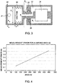
- Figure 3 is a further example not forming part of the invention, of a pressure balancing device 1, except instead of using a piston or bladder, a bellows 40 is used as the pressure transmission device.
- the effective cross-sectional area A 1 of the bellows 40 is larger than the cross-sectional area of the hollow shaft A 2 resulting in a reduced error e for the device.
- the results are also presented graphically in figure 4 .
- the measurement error is reduced as the area Ratio is reduced, in this example by reducing the area of the cross-section of the hollow shaft 23.
- the area ratio (A 2 /A 1 ) may be equal to or less then 0.8, 0.7, 0.6, 0.5, 0.4, 0.3, 0.2 or 0.1 for example.
- the examples provided in Table 1 above are for a pressure balancing device 1 with the pressure transmission device 10 having a cross-sectional area of 725mm 2
- the examples of the present invention could be used with a pressure balancing device 1 having a pressure transmission device 10 of any appropriate cross-sectional area A 1 .
- the pressure transmission device 10 may have as large a cross-sectional area A 1 as can be practically or conveniently provided.
- the cross-sectional area A 1 of the pressure transmission device 10 would, in practice, probably be limited by the particular application in which it is being used and the available space for the pressure balancing device 1. For example, if used in a downhole tool then the cross-sectional area will be limited by the available space in the tool and is likely to be a few 1000mm 2 or less.
Landscapes
- Physics & Mathematics (AREA)
- Geology (AREA)
- Life Sciences & Earth Sciences (AREA)
- Engineering & Computer Science (AREA)
- Mining & Mineral Resources (AREA)
- Environmental & Geological Engineering (AREA)
- Fluid Mechanics (AREA)
- Geophysics (AREA)
- General Life Sciences & Earth Sciences (AREA)
- Geochemistry & Mineralogy (AREA)
- General Physics & Mathematics (AREA)
- Measuring Fluid Pressure (AREA)
- Diaphragms And Bellows (AREA)
- Force Measurement Appropriate To Specific Purposes (AREA)
Description
- The present invention relates to a pressure balancing device, such as for a transducer.
- Downhole logging tools are frequently designed to be pressure balanced. This is where a measurement sensor is located within the body of the tool and is protected from well fluid by appropriate sealed housings, but where some form of pressure transmission device is used to compress a fluid within the tool to approximately the same pressure as the well fluid outside. In this manner, the sensor is exposed to the well pressure, without suffering the consequences of being immersed directly in the well fluid. The compensating mechanism must also allow for the internal fluid to expand at low pressure but high temperature.
- Pressure compensating mechanisms regularly used downhole include pistons, rubber bladders and flexible metal bellows. Each mechanism has advantages and disadvantages in terms of the resulting pressure difference between the inside and outside of the tool, such as maintainability, cost, durability and resistance to attack from the chemicals in the well. Of these methods, compensating pistons are often used, due to their simple design and rugged construction. However, inherent in the design of a piston compensating system is the need for dynamic sliding seals, which experience high hydrostatic pressures and therefore suffer from high friction, and resist the motion of the piston. This resistance to motion results in a differential pressure across the piston, which corresponds to a minimum force required to move the piston against its seals. The higher the seal friction, the larger the differential pressure will be between the inside and the outside of the tool. In cases where the sensor inside the tool needs to be at the same pressure as the well fluid for accurate measurement, this differential pressure results in measurement error and is undesirable. In a similar manner both the bladder and the flexible metal bellows have stiffness in their structures, which resist motion and hence, generate a differential pressure.
- A typical example of a downhole pressure sensitive device is a cable head load measuring tool. This tool is placed at the top of a logging tool string and is designed to report to the user the force being exerted on the tool string by the wireline or tractoring tool. Essentially, the tool must measure differential axial loading in the string, but not the axial load produced solely by the well pressure surrounding the string. Using a pressure balanced load measuring sensor is one solution, which inherently requires a good pressure compensating device.
-
EP 0 098 790 - The present invention provides a pressure balancing device for a transducer as defined in claim 1.
- Consequently, an improved downhole tool pressure balancing method, not forming part of the invention, is provided for transducers, which is sensitive to differential pressure between an oil well for example and the tool interior. Using established pressure balancing mechanisms such as pistons, flexible bellows and rubber bladders, the area ratio of the compensation device and a shaft passing through a mandrel is carefully controlled so as to reduce the impact of differential pressure created by compensator friction or stiffness on the induced transducer error. The hollow shaft may be a load transmission shaft which may be connected to a load sensor.
- The area ratio of the piston and the mandrel around the shaft have a ratio smaller than 1, such as less than 0.8 or less then 0.7, for example rather than equal to 1. This reduces the effect of the compensator/pressure transmission device friction/stiffness on the measured variable.
- The improved pressure balancing configuration allows pressure sensitive transducers to suffer less measurement error than a conventional pressure balancing system. In the case of the cable head load measuring tool, the configuration results in increased accuracy and reduced hysteresis due to pressure changes over a system using a conventional pressure compensator.
- Increased accuracy makes the use of the device in a downhole tool such as a downhole load measuring tool significantly more attractive to users as they can more confidently measure the load being exerted on the toolstring and predict when the cable head will reach breaking point. Balancing the load between the wireline and tractor during deviated well operations, can also be controlled more successfully.
- Embodiments of the present invention will now be described, by way of example only, with reference to the accompanying drawings, in which:
-
Figure 1 shows a first example of a pressure balancing device for a transducer; -
Figure 2 shows a second example of a pressure balancing device for a transducer, which is not part of the present invention; -
Figure 3 shows a third example of a pressure balancing device for a transducer, which is not part of the present invention; and -
Figure 4 shows the resulting error (e) for a pressure balancing device with hollow shafts of various cross-sectional areas (A2) - As shown in
figure 1 , the pressure balancing device 1 of this example has apressure transmission device 10, which in this example is a piston, provided in ahousing 20. Instead of a piston, thepressure transmission device 10 could for example be a rubber bladder or a flexible metal bellows. The piston is sealed against the inside surface of thehousing 20 by aseal 11. The device 1 is exposed to external pressure Pw throughinlet 21. The pressure balancing device 1 has a sealedchamber 22 with internal pressure Pt. Thechamber 22 has ahollow shaft 23 and atransducer 24. Movement of thepressure transmission device 10 may direct internal fluid through thehollow shaft 23 into or out of the sealedchamber 22. In this example thetransducer 24 is a load sensor and thehollow shaft 23 is a load transmission shaft. The device 1 may be arranged to measure a load across it in the direction of theshaft 23. In this example theshaft 23 is arranged to pass through amandrel 25 which has anO ring seal 26. Thepiston 10 is moved back and forth as shown by arrow F depending upon the external pressure Pw and internal pressure Pt with resistance force F to motion/deformation of the piston/pressure transmission device 10. Various characteristics shown in the figure are defined as follows: - D1 is the diameter of the piston.
- D2 is the diameter of the hollow load transmission shaft.
- Pw is the external pressure, for example the pressure in a well.
- Pt is the internal tool pressure.
- F is the resistance force to motion/deformation of the compensator.
- Depending on the exact configuration of the mechanism, the piston diameter D1 will have a cross-sectional area A1 associated with it. Similarly, the load transmission shaft will have a cross sectional area A2 associated with diameter D2. If the error induced in the sensor due to differential pressure between the inside and the outside of the tool is e and the ratio of areas is R, then:
Differential pressure


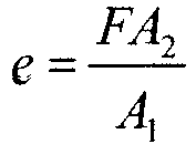

e = RF
Therefore, for the error e to be smaller than the resistance force F, R<1. - This implies that to reduce the effect of the piston/
compensator 10 on the measured force, the compensator area should be large, while the load transmission shaft area should be small. Taken to the extreme case, with an infinitely large compensator or an infinitely small shaft, the error will be zero. In practice, this ideal case is impossible to achieve and generally, with the limitations on diameter which are experienced in downhole tool design, the area of theshaft 23 is preferably at least a minimum amount to provide sufficient strength and robustness for the intended use, such as in a downhole tool. The areas of the pressure transmission device A1 and the shaft A2 are preferably within an order of magnitude of each other. Therefore, embodiments of this invention consider the case when R is smaller than 1, which produces overall error reduction. -
Figure 2 shows a further example of a pressure balancing device in accordance with the present invention. The device offigure 2 is not part of the present invention, but is very similar to that tofigure 1 , except instead of using a piston, abladder 30 is used as thepressure transmission device 10. The same principles as explained withfigure 1 are also applicable to the example offigure 2 except with the cross-sectional area A1 being the effective cross-sectional area of thebladder 30 exposed to the external pressure Pw viainlet 21. -
Figure 3 is a further example not forming part of the invention, of a pressure balancing device 1, except instead of using a piston or bladder, abellows 40 is used as the pressure transmission device. Like the examples offigures 1 and 2 , the effective cross-sectional area A1 of thebellows 40 is larger than the cross-sectional area of the hollow shaft A2 resulting in a reduced error e for the device. - Some experiments were performed on a pressure balancing device 1 as shown in our
figure 1 with a cross-sectional area A1 of thepressure transmission device 10 of 725mm2 with the pressure balancing device 1 subjected to a driving force F of 1 Newton. The pressure balancing device 1 was fitted withhollow shafts 23 of differing cross-sectional areas A2 as listed in Table 1 below and the measurement error in Newtons determined for eachhollow shaft 23.Table 1 A2 (mm^2) Area Ratio R (A2/A1) Measurement error (N) (=RxF) 444 0.612413793 0.612413793 400 0.551724138 0.551724138 300 0.413793103 0.413793103 200 0.275862069 0.275862069 100 0.137931034 0.137931034 A1 (mm^2) 725 Driving force F (N) 1 - The results are also presented graphically in
figure 4 . As can be seen from Table 1 andfigure 4 , the measurement error is reduced as the area Ratio is reduced, in this example by reducing the area of the cross-section of thehollow shaft 23. The area ratio (A2/A1) may be equal to or less then 0.8, 0.7, 0.6, 0.5, 0.4, 0.3, 0.2 or 0.1 for example. - We have found that whilst reducing the area ratio (A2/A1) reduces the error, reducing the cross-sectional area of the hollow shaft too far may compromise the mechanical strength and robustness of the pressure balancing device. In practice, it has been found to be preferable to maintain the area ratio (A2/A1) at 0.1 or greater.
- Whilst the examples provided in Table 1 above are for a pressure balancing device 1 with the
pressure transmission device 10 having a cross-sectional area of 725mm2, clearly the examples of the present invention could be used with a pressure balancing device 1 having apressure transmission device 10 of any appropriate cross-sectional area A1. In practice, thepressure transmission device 10 may have as large a cross-sectional area A1 as can be practically or conveniently provided. However, the cross-sectional area A1 of thepressure transmission device 10 would, in practice, probably be limited by the particular application in which it is being used and the available space for the pressure balancing device 1. For example, if used in a downhole tool then the cross-sectional area will be limited by the available space in the tool and is likely to be a few 1000mm2 or less. - Many variations may be made to the examples described above while still falling within the present invention. For example, whilst the pressure balancing devices of
figure 1 have been described for use in a downhole tool, such as a downhole load measuring tool, the pressure balancing devices may be used in any application. it is also noted that whilst the examples of the pressure balancing device have been used with a load sensor as a transducer, any appropriate transducer may be used in appropriate circumstances, such as a pressure transducer for example. The scope of the invention is defined by the appended claims.
Claims (7)
- A pressure balancing device (1) for a transducer (24), the pressure balancing device (1) comprising:a housing (20), a piston (10) provided in the housing, and sealed against an inside surface of the housing (20) by a seal (11), the piston (10) having a cross-sectional area and arranged, in use, to be exposed to a fluid; anda fluid chamber (22) having a hollow shaft (23), the fluid chamber being arranged to be acted on by the piston (10), and the fluid chamber (22) being fluidly coupled with the piston (10) and a load sensor (24) such that movement or deformation of the piston (10) directs internal fluid through the hollow shaft (23) into or out of the sealed chamber (22);wherein the cross-sectional area of the hollow shaft (23) is less than the cross-sectional area of the piston (10).
- A pressure balancing device (1) according to claim 1, wherein the hollow shaft (23) is a load transmission shaft.
- A pressure balancing device (1) according to claim 2, wherein the load transmission shaft is connected to a load sensor (24).
- A pressure balancing device (1) according to any preceding claim, wherein the ratio of the cross-sectional area of the hollow shaft A2 (23) to the cross-sectional area of the pressure transmission device A1 (10) A2/A1, is 0.8 or less.
- A pressure balancing device (1) according to any preceding claim, wherein the ratio of the cross-sectional area of the hollow shaft A2 (23) to the cross-sectional area of the pressure transmission device A1 (10) A2/A1, is 0.7 or less.
- A downhole tool including a pressure balancing device (1) according to any preceding claim.
- A downhole load measuring tool including a pressure balancing device (1) of any one of claims 1 to 5.
Applications Claiming Priority (1)
| Application Number | Priority Date | Filing Date | Title |
|---|---|---|---|
| GBGB1007811.1A GB201007811D0 (en) | 2010-05-11 | 2010-05-11 | Pressure balancing device |
Publications (3)
| Publication Number | Publication Date |
|---|---|
| EP2386719A2 EP2386719A2 (en) | 2011-11-16 |
| EP2386719A3 EP2386719A3 (en) | 2017-07-05 |
| EP2386719B1 true EP2386719B1 (en) | 2021-04-14 |
Family
ID=42315107
Family Applications (1)
| Application Number | Title | Priority Date | Filing Date |
|---|---|---|---|
| EP11164922.4A Active EP2386719B1 (en) | 2010-05-11 | 2011-05-05 | Pressure balancing device |
Country Status (5)
| Country | Link |
|---|---|
| US (1) | US8689620B2 (en) |
| EP (1) | EP2386719B1 (en) |
| CN (1) | CN102322257B (en) |
| CA (1) | CA2739214C (en) |
| GB (1) | GB201007811D0 (en) |
Families Citing this family (11)
| Publication number | Priority date | Publication date | Assignee | Title |
|---|---|---|---|---|
| EP2893135B1 (en) * | 2012-09-26 | 2022-04-20 | Halliburton Energy Services, Inc. | Method of placing distributed pressure gauges across screens |
| US9598952B2 (en) * | 2012-09-26 | 2017-03-21 | Halliburton Energy Services, Inc. | Snorkel tube with debris barrier for electronic gauges placed on sand screens |
| US9085962B2 (en) | 2012-09-26 | 2015-07-21 | Halliburton Energy Services, Inc. | Snorkel tube with debris barrier for electronic gauges placed on sand screens |
| EP2940246A1 (en) * | 2014-05-02 | 2015-11-04 | Piezotech, LLC | Pressure-compensated transducer assembly |
| US20160053582A1 (en) * | 2014-08-19 | 2016-02-25 | C&J Energy Services, Inc. | Tool With Modular Pressure Compensator And Related Methods |
| CA2984462C (en) | 2015-07-02 | 2018-12-11 | Halliburton Energy Services, Inc. | Pressure balanced transducer assembly and measurement tool |
| US10267097B2 (en) * | 2016-11-09 | 2019-04-23 | Baker Hughes, A Ge Company, Llc | Pressure compensating connector system, downhole assembly, and method |
| US11143018B2 (en) * | 2017-10-16 | 2021-10-12 | Halliburton Energy Services, Inc. | Environmental compensation system for downhole oilwell tools |
| CN108181039B (en) * | 2017-12-29 | 2020-02-07 | 泉州市大西洋电力科技有限公司 | Hydraulic sensor |
| US12460540B2 (en) * | 2022-09-27 | 2025-11-04 | Baker Hughes Oilfield Operations Llc | Pressure sensor and borehole system |
| CN116273810B (en) * | 2023-02-20 | 2025-08-05 | 上海船舶电子设备研究所(中国船舶集团有限公司第七二六研究所) | Adaptive pressure-compensated type III flextensional transducer |
Family Cites Families (26)
| Publication number | Priority date | Publication date | Assignee | Title |
|---|---|---|---|---|
| US1396844A (en) * | 1920-06-29 | 1921-11-15 | Edwin E Huffman | Depth-indicating device |
| US1661995A (en) * | 1924-10-28 | 1928-03-06 | Brown Kirk | Gauge for liquids |
| US3213414A (en) * | 1962-08-27 | 1965-10-19 | Schlumberger Well Surv Corp | Acoustic transducer with pressure equalizing cover |
| US3633414A (en) * | 1970-04-27 | 1972-01-11 | Geophysical Res Corp | Method and apparatus for measuring rate of bottom hole pressure change |
| US3633696A (en) * | 1970-10-15 | 1972-01-11 | United States Steel Corp | Load cell |
| US3744307A (en) * | 1972-06-28 | 1973-07-10 | Geophysical Res Corp | Pressure gauge |
| US3810387A (en) * | 1972-12-08 | 1974-05-14 | Sperry Sun Well Surveying Co | Apparatus for recording borehole conditions at the surface |
| US3851717A (en) | 1973-11-15 | 1974-12-03 | Baker Oil Tools Inc | Substantially constant time delay fishing jar |
| US4358956A (en) * | 1979-04-13 | 1982-11-16 | Emdee Corporation | Liquid level indicator |
| US4227410A (en) * | 1979-04-13 | 1980-10-14 | Emdee Corporation | Attitude compensating indicator |
| US4252015A (en) * | 1979-06-20 | 1981-02-24 | Phillips Petroleum Company | Wellbore pressure testing method and apparatus |
| US4266606A (en) * | 1979-08-27 | 1981-05-12 | Teleco Oilfield Services Inc. | Hydraulic circuit for borehole telemetry apparatus |
| US4359899A (en) * | 1980-12-19 | 1982-11-23 | Dresser Industries, Inc. | Weight on drill bit measuring apparatus |
| SE434679B (en) * | 1982-07-01 | 1984-08-06 | Asea Ab | DEVICE FOR HERMETICALLY CLOSED LOAD CELLS FOR ELIMINATING THE IMPACT OF THE DIFFERENCE BETWEEN PRESSURE IN A SENSOR SPACE AND ATMOSPHERIC PRESSURE |
| GB8620212D0 (en) * | 1986-08-20 | 1986-10-01 | Drexel Equipment Ltd | Downhole pressure & temperature gauges |
| US4787447A (en) * | 1987-06-19 | 1988-11-29 | Halliburton Company | Well fluid modular sampling apparatus |
| US4865125A (en) | 1988-09-09 | 1989-09-12 | Douglas W. Crawford | Hydraulic jar mechanism |
| FR2638524B1 (en) * | 1988-10-27 | 1994-10-28 | Schlumberger Prospection | PRESSURE SENSOR FOR USE IN OIL WELLS |
| DE19537149A1 (en) * | 1995-10-05 | 1997-04-10 | Ott Mestechnik Gmbh & Co Kg | Method and measuring device for measuring the hydrostatic pressure, in particular the groundwater |
| US6439055B1 (en) * | 1999-11-15 | 2002-08-27 | Weatherford/Lamb, Inc. | Pressure sensor assembly structure to insulate a pressure sensing device from harsh environments |
| US6481495B1 (en) | 2000-09-25 | 2002-11-19 | Robert W. Evans | Downhole tool with electrical conductor |
| US6988551B2 (en) | 2003-11-04 | 2006-01-24 | Evans Robert W | Jar with adjustable trigger load |
| US7311149B2 (en) | 2003-11-04 | 2007-12-25 | Evans Robert W | Jar with adjustable preload |
| US7290604B2 (en) | 2003-11-04 | 2007-11-06 | Evans Robert W | Downhole tool with pressure balancing |
| US7559361B2 (en) | 2005-07-14 | 2009-07-14 | Star Oil Tools, Inc. | Downhole force generator |
| CN201635727U (en) * | 2010-04-20 | 2010-11-17 | 中国石油集团川庆钻探工程有限公司井下作业公司 | Underground construction monitor for bottom hole wireless data transmission in continuous coiled tubing operation |
-
2010
- 2010-05-11 GB GBGB1007811.1A patent/GB201007811D0/en not_active Ceased
-
2011
- 2011-05-03 US US13/099,471 patent/US8689620B2/en not_active Expired - Fee Related
- 2011-05-05 CA CA2739214A patent/CA2739214C/en active Active
- 2011-05-05 EP EP11164922.4A patent/EP2386719B1/en active Active
- 2011-05-11 CN CN201110132683.2A patent/CN102322257B/en not_active Expired - Fee Related
Non-Patent Citations (1)
| Title |
|---|
| None * |
Also Published As
| Publication number | Publication date |
|---|---|
| GB201007811D0 (en) | 2010-06-23 |
| CN102322257A (en) | 2012-01-18 |
| CA2739214C (en) | 2018-03-13 |
| US8689620B2 (en) | 2014-04-08 |
| CN102322257B (en) | 2016-06-01 |
| US20110277545A1 (en) | 2011-11-17 |
| EP2386719A2 (en) | 2011-11-16 |
| CA2739214A1 (en) | 2011-11-11 |
| EP2386719A3 (en) | 2017-07-05 |
Similar Documents
| Publication | Publication Date | Title |
|---|---|---|
| US8689620B2 (en) | Pressure balancing device | |
| RU2377404C2 (en) | Method for change of well boring equipment loading | |
| US8662205B2 (en) | System and method for damping vibration in a drill string | |
| CN102741503B (en) | For measuring the equipment of the bending on the drill bit worked in well | |
| EP0353838B1 (en) | Weight-on-bit and torque measuring apparatus | |
| US9038452B2 (en) | Systems and methods for measuring forces acting on a downhole tool | |
| US4460181A (en) | Method and mechanism for controlling the pressure at shaft-sealing part of an apparatus | |
| US8739868B2 (en) | System and method of strain measurement amplification | |
| US8333117B2 (en) | Isolation elements including one or more diaphragms, sensors including isolation elements, and related methods | |
| CN104204552B (en) | Vibration damping system by means of hydraulic actuation system | |
| US3827294A (en) | Well bore force-measuring apparatus | |
| US3864968A (en) | Force-measuring apparatus for use in a well bore pipe string | |
| US9016141B2 (en) | Dry pressure compensated sensor | |
| US8671749B2 (en) | System and method to protect strain gauges while transmitting pressure | |
| JPS6221117B2 (en) | ||
| KR101724329B1 (en) | Backlash and stiffness measuring apparatus in an actuator | |
| CN100595591C (en) | Two-dimensional Magnetic Fluid Acceleration Sensor | |
| CN110382819B (en) | Buffer tool for downhole tool string | |
| CN211373920U (en) | Vacuum pressure gauge and pressure sensing mechanism | |
| US11898426B2 (en) | Submersible electric motor with a system for maintaining a constant positive pressure | |
| JP4477588B2 (en) | Reciprocating compressor | |
| SU1170129A1 (en) | Hole-bottom apparatus for measuring axial load | |
| CN112286241B (en) | Pressure balancing device and engineering machinery | |
| JPH0625719B2 (en) | Alternating fatigue testing machine | |
| WO2012051480A2 (en) | Acoustic transducers with dynamic frequency range |
Legal Events
| Date | Code | Title | Description |
|---|---|---|---|
| AK | Designated contracting states |
Kind code of ref document: A2 Designated state(s): AL AT BE BG CH CY CZ DE DK EE ES FI FR GB GR HR HU IE IS IT LI LT LU LV MC MK MT NL NO PL PT RO RS SE SI SK SM TR |
|
| AX | Request for extension of the european patent |
Extension state: BA ME |
|
| PUAI | Public reference made under article 153(3) epc to a published international application that has entered the european phase |
Free format text: ORIGINAL CODE: 0009012 |
|
| PUAL | Search report despatched |
Free format text: ORIGINAL CODE: 0009013 |
|
| AK | Designated contracting states |
Kind code of ref document: A3 Designated state(s): AL AT BE BG CH CY CZ DE DK EE ES FI FR GB GR HR HU IE IS IT LI LT LU LV MC MK MT NL NO PL PT RO RS SE SI SK SM TR |
|
| AX | Request for extension of the european patent |
Extension state: BA ME |
|
| RIC1 | Information provided on ipc code assigned before grant |
Ipc: E21B 47/06 20120101ALI20170531BHEP Ipc: G01L 1/00 20060101ALI20170531BHEP Ipc: E21B 47/00 20120101ALI20170531BHEP Ipc: E21B 47/01 20120101AFI20170531BHEP |
|
| STAA | Information on the status of an ep patent application or granted ep patent |
Free format text: STATUS: REQUEST FOR EXAMINATION WAS MADE |
|
| 17P | Request for examination filed |
Effective date: 20180105 |
|
| RBV | Designated contracting states (corrected) |
Designated state(s): AL AT BE BG CH CY CZ DE DK EE ES FI FR GB GR HR HU IE IS IT LI LT LU LV MC MK MT NL NO PL PT RO RS SE SI SK SM TR |
|
| STAA | Information on the status of an ep patent application or granted ep patent |
Free format text: STATUS: EXAMINATION IS IN PROGRESS |
|
| 17Q | First examination report despatched |
Effective date: 20180928 |
|
| GRAP | Despatch of communication of intention to grant a patent |
Free format text: ORIGINAL CODE: EPIDOSNIGR1 |
|
| STAA | Information on the status of an ep patent application or granted ep patent |
Free format text: STATUS: GRANT OF PATENT IS INTENDED |
|
| INTG | Intention to grant announced |
Effective date: 20201118 |
|
| RIN1 | Information on inventor provided before grant (corrected) |
Inventor name: GILL, TIMOTHY MICHAEL Inventor name: BROOM, NICHOLAS PETER Inventor name: RATCLIFFE, JAMES DAVID |
|
| GRAS | Grant fee paid |
Free format text: ORIGINAL CODE: EPIDOSNIGR3 |
|
| GRAA | (expected) grant |
Free format text: ORIGINAL CODE: 0009210 |
|
| STAA | Information on the status of an ep patent application or granted ep patent |
Free format text: STATUS: THE PATENT HAS BEEN GRANTED |
|
| AK | Designated contracting states |
Kind code of ref document: B1 Designated state(s): AL AT BE BG CH CY CZ DE DK EE ES FI FR GB GR HR HU IE IS IT LI LT LU LV MC MK MT NL NO PL PT RO RS SE SI SK SM TR |
|
| REG | Reference to a national code |
Ref country code: GB Ref legal event code: FG4D |
|
| REG | Reference to a national code |
Ref country code: CH Ref legal event code: EP |
|
| REG | Reference to a national code |
Ref country code: DE Ref legal event code: R096 Ref document number: 602011070671 Country of ref document: DE |
|
| REG | Reference to a national code |
Ref country code: IE Ref legal event code: FG4D |
|
| REG | Reference to a national code |
Ref country code: AT Ref legal event code: REF Ref document number: 1382539 Country of ref document: AT Kind code of ref document: T Effective date: 20210515 |
|
| REG | Reference to a national code |
Ref country code: NO Ref legal event code: T2 Effective date: 20210414 |
|
| REG | Reference to a national code |
Ref country code: LT Ref legal event code: MG9D |
|
| REG | Reference to a national code |
Ref country code: AT Ref legal event code: MK05 Ref document number: 1382539 Country of ref document: AT Kind code of ref document: T Effective date: 20210414 |
|
| REG | Reference to a national code |
Ref country code: NL Ref legal event code: MP Effective date: 20210414 |
|
| PG25 | Lapsed in a contracting state [announced via postgrant information from national office to epo] |
Ref country code: FI Free format text: LAPSE BECAUSE OF FAILURE TO SUBMIT A TRANSLATION OF THE DESCRIPTION OR TO PAY THE FEE WITHIN THE PRESCRIBED TIME-LIMIT Effective date: 20210414 Ref country code: LT Free format text: LAPSE BECAUSE OF FAILURE TO SUBMIT A TRANSLATION OF THE DESCRIPTION OR TO PAY THE FEE WITHIN THE PRESCRIBED TIME-LIMIT Effective date: 20210414 Ref country code: NL Free format text: LAPSE BECAUSE OF FAILURE TO SUBMIT A TRANSLATION OF THE DESCRIPTION OR TO PAY THE FEE WITHIN THE PRESCRIBED TIME-LIMIT Effective date: 20210414 Ref country code: HR Free format text: LAPSE BECAUSE OF FAILURE TO SUBMIT A TRANSLATION OF THE DESCRIPTION OR TO PAY THE FEE WITHIN THE PRESCRIBED TIME-LIMIT Effective date: 20210414 Ref country code: AT Free format text: LAPSE BECAUSE OF FAILURE TO SUBMIT A TRANSLATION OF THE DESCRIPTION OR TO PAY THE FEE WITHIN THE PRESCRIBED TIME-LIMIT Effective date: 20210414 Ref country code: BG Free format text: LAPSE BECAUSE OF FAILURE TO SUBMIT A TRANSLATION OF THE DESCRIPTION OR TO PAY THE FEE WITHIN THE PRESCRIBED TIME-LIMIT Effective date: 20210714 |
|
| PG25 | Lapsed in a contracting state [announced via postgrant information from national office to epo] |
Ref country code: PL Free format text: LAPSE BECAUSE OF FAILURE TO SUBMIT A TRANSLATION OF THE DESCRIPTION OR TO PAY THE FEE WITHIN THE PRESCRIBED TIME-LIMIT Effective date: 20210414 Ref country code: PT Free format text: LAPSE BECAUSE OF FAILURE TO SUBMIT A TRANSLATION OF THE DESCRIPTION OR TO PAY THE FEE WITHIN THE PRESCRIBED TIME-LIMIT Effective date: 20210816 Ref country code: ES Free format text: LAPSE BECAUSE OF FAILURE TO SUBMIT A TRANSLATION OF THE DESCRIPTION OR TO PAY THE FEE WITHIN THE PRESCRIBED TIME-LIMIT Effective date: 20210414 Ref country code: GR Free format text: LAPSE BECAUSE OF FAILURE TO SUBMIT A TRANSLATION OF THE DESCRIPTION OR TO PAY THE FEE WITHIN THE PRESCRIBED TIME-LIMIT Effective date: 20210715 Ref country code: LV Free format text: LAPSE BECAUSE OF FAILURE TO SUBMIT A TRANSLATION OF THE DESCRIPTION OR TO PAY THE FEE WITHIN THE PRESCRIBED TIME-LIMIT Effective date: 20210414 Ref country code: IS Free format text: LAPSE BECAUSE OF FAILURE TO SUBMIT A TRANSLATION OF THE DESCRIPTION OR TO PAY THE FEE WITHIN THE PRESCRIBED TIME-LIMIT Effective date: 20210814 Ref country code: SE Free format text: LAPSE BECAUSE OF FAILURE TO SUBMIT A TRANSLATION OF THE DESCRIPTION OR TO PAY THE FEE WITHIN THE PRESCRIBED TIME-LIMIT Effective date: 20210414 Ref country code: RS Free format text: LAPSE BECAUSE OF FAILURE TO SUBMIT A TRANSLATION OF THE DESCRIPTION OR TO PAY THE FEE WITHIN THE PRESCRIBED TIME-LIMIT Effective date: 20210414 |
|
| REG | Reference to a national code |
Ref country code: DE Ref legal event code: R119 Ref document number: 602011070671 Country of ref document: DE |
|
| REG | Reference to a national code |
Ref country code: CH Ref legal event code: PL |
|
| PG25 | Lapsed in a contracting state [announced via postgrant information from national office to epo] |
Ref country code: RO Free format text: LAPSE BECAUSE OF FAILURE TO SUBMIT A TRANSLATION OF THE DESCRIPTION OR TO PAY THE FEE WITHIN THE PRESCRIBED TIME-LIMIT Effective date: 20210414 Ref country code: LI Free format text: LAPSE BECAUSE OF NON-PAYMENT OF DUE FEES Effective date: 20210531 Ref country code: LU Free format text: LAPSE BECAUSE OF NON-PAYMENT OF DUE FEES Effective date: 20210505 Ref country code: MC Free format text: LAPSE BECAUSE OF FAILURE TO SUBMIT A TRANSLATION OF THE DESCRIPTION OR TO PAY THE FEE WITHIN THE PRESCRIBED TIME-LIMIT Effective date: 20210414 Ref country code: CH Free format text: LAPSE BECAUSE OF NON-PAYMENT OF DUE FEES Effective date: 20210531 Ref country code: EE Free format text: LAPSE BECAUSE OF FAILURE TO SUBMIT A TRANSLATION OF THE DESCRIPTION OR TO PAY THE FEE WITHIN THE PRESCRIBED TIME-LIMIT Effective date: 20210414 Ref country code: CZ Free format text: LAPSE BECAUSE OF FAILURE TO SUBMIT A TRANSLATION OF THE DESCRIPTION OR TO PAY THE FEE WITHIN THE PRESCRIBED TIME-LIMIT Effective date: 20210414 Ref country code: DK Free format text: LAPSE BECAUSE OF FAILURE TO SUBMIT A TRANSLATION OF THE DESCRIPTION OR TO PAY THE FEE WITHIN THE PRESCRIBED TIME-LIMIT Effective date: 20210414 Ref country code: SK Free format text: LAPSE BECAUSE OF FAILURE TO SUBMIT A TRANSLATION OF THE DESCRIPTION OR TO PAY THE FEE WITHIN THE PRESCRIBED TIME-LIMIT Effective date: 20210414 Ref country code: SM Free format text: LAPSE BECAUSE OF FAILURE TO SUBMIT A TRANSLATION OF THE DESCRIPTION OR TO PAY THE FEE WITHIN THE PRESCRIBED TIME-LIMIT Effective date: 20210414 |
|
| REG | Reference to a national code |
Ref country code: BE Ref legal event code: MM Effective date: 20210531 |
|
| PLBE | No opposition filed within time limit |
Free format text: ORIGINAL CODE: 0009261 |
|
| STAA | Information on the status of an ep patent application or granted ep patent |
Free format text: STATUS: NO OPPOSITION FILED WITHIN TIME LIMIT |
|
| 26N | No opposition filed |
Effective date: 20220117 |
|
| PG25 | Lapsed in a contracting state [announced via postgrant information from national office to epo] |
Ref country code: IE Free format text: LAPSE BECAUSE OF NON-PAYMENT OF DUE FEES Effective date: 20210505 Ref country code: DE Free format text: LAPSE BECAUSE OF NON-PAYMENT OF DUE FEES Effective date: 20211201 |
|
| PG25 | Lapsed in a contracting state [announced via postgrant information from national office to epo] |
Ref country code: IS Free format text: LAPSE BECAUSE OF FAILURE TO SUBMIT A TRANSLATION OF THE DESCRIPTION OR TO PAY THE FEE WITHIN THE PRESCRIBED TIME-LIMIT Effective date: 20210814 Ref country code: FR Free format text: LAPSE BECAUSE OF NON-PAYMENT OF DUE FEES Effective date: 20210614 Ref country code: AL Free format text: LAPSE BECAUSE OF FAILURE TO SUBMIT A TRANSLATION OF THE DESCRIPTION OR TO PAY THE FEE WITHIN THE PRESCRIBED TIME-LIMIT Effective date: 20210414 |
|
| PG25 | Lapsed in a contracting state [announced via postgrant information from national office to epo] |
Ref country code: IT Free format text: LAPSE BECAUSE OF FAILURE TO SUBMIT A TRANSLATION OF THE DESCRIPTION OR TO PAY THE FEE WITHIN THE PRESCRIBED TIME-LIMIT Effective date: 20210414 Ref country code: BE Free format text: LAPSE BECAUSE OF NON-PAYMENT OF DUE FEES Effective date: 20210531 |
|
| PG25 | Lapsed in a contracting state [announced via postgrant information from national office to epo] |
Ref country code: HU Free format text: LAPSE BECAUSE OF FAILURE TO SUBMIT A TRANSLATION OF THE DESCRIPTION OR TO PAY THE FEE WITHIN THE PRESCRIBED TIME-LIMIT; INVALID AB INITIO Effective date: 20110505 Ref country code: CY Free format text: LAPSE BECAUSE OF FAILURE TO SUBMIT A TRANSLATION OF THE DESCRIPTION OR TO PAY THE FEE WITHIN THE PRESCRIBED TIME-LIMIT Effective date: 20210414 |
|
| P01 | Opt-out of the competence of the unified patent court (upc) registered |
Effective date: 20230526 |
|
| PG25 | Lapsed in a contracting state [announced via postgrant information from national office to epo] |
Ref country code: MK Free format text: LAPSE BECAUSE OF FAILURE TO SUBMIT A TRANSLATION OF THE DESCRIPTION OR TO PAY THE FEE WITHIN THE PRESCRIBED TIME-LIMIT Effective date: 20210414 |
|
| PG25 | Lapsed in a contracting state [announced via postgrant information from national office to epo] |
Ref country code: MT Free format text: LAPSE BECAUSE OF FAILURE TO SUBMIT A TRANSLATION OF THE DESCRIPTION OR TO PAY THE FEE WITHIN THE PRESCRIBED TIME-LIMIT Effective date: 20210414 |
|
| PGFP | Annual fee paid to national office [announced via postgrant information from national office to epo] |
Ref country code: GB Payment date: 20250423 Year of fee payment: 15 |
|
| PGFP | Annual fee paid to national office [announced via postgrant information from national office to epo] |
Ref country code: NO Payment date: 20250424 Year of fee payment: 15 |
|
| PG25 | Lapsed in a contracting state [announced via postgrant information from national office to epo] |
Ref country code: TR Free format text: LAPSE BECAUSE OF FAILURE TO SUBMIT A TRANSLATION OF THE DESCRIPTION OR TO PAY THE FEE WITHIN THE PRESCRIBED TIME-LIMIT Effective date: 20210414 |