EP2386701A1 - A door handle for a domestic appliance - Google Patents
A door handle for a domestic appliance Download PDFInfo
- Publication number
- EP2386701A1 EP2386701A1 EP10005102A EP10005102A EP2386701A1 EP 2386701 A1 EP2386701 A1 EP 2386701A1 EP 10005102 A EP10005102 A EP 10005102A EP 10005102 A EP10005102 A EP 10005102A EP 2386701 A1 EP2386701 A1 EP 2386701A1
- Authority
- EP
- European Patent Office
- Prior art keywords
- bracket portion
- handle bar
- door handle
- door
- contact elements
- Prior art date
- Legal status (The legal status is an assumption and is not a legal conclusion. Google has not performed a legal analysis and makes no representation as to the accuracy of the status listed.)
- Withdrawn
Links
- 230000000295 complement effect Effects 0.000 claims abstract description 7
- 239000002184 metal Substances 0.000 claims description 8
- 239000000463 material Substances 0.000 claims description 7
- 239000004033 plastic Substances 0.000 claims description 6
- 229920003023 plastic Polymers 0.000 claims description 6
- 239000000853 adhesive Substances 0.000 claims description 3
- 230000001070 adhesive effect Effects 0.000 claims description 3
- 238000010411 cooking Methods 0.000 description 3
- 239000000919 ceramic Substances 0.000 description 2
- 239000011521 glass Substances 0.000 description 2
- 238000012986 modification Methods 0.000 description 2
- 230000004048 modification Effects 0.000 description 2
- 239000012212 insulator Substances 0.000 description 1
- 230000000149 penetrating effect Effects 0.000 description 1
- 230000000704 physical effect Effects 0.000 description 1
Images

Classifications
-
- E—FIXED CONSTRUCTIONS
- E05—LOCKS; KEYS; WINDOW OR DOOR FITTINGS; SAFES
- E05B—LOCKS; ACCESSORIES THEREFOR; HANDCUFFS
- E05B1/00—Knobs or handles for wings; Knobs, handles, or press buttons for locks or latches on wings
-
- E—FIXED CONSTRUCTIONS
- E05—LOCKS; KEYS; WINDOW OR DOOR FITTINGS; SAFES
- E05B—LOCKS; ACCESSORIES THEREFOR; HANDCUFFS
- E05B1/00—Knobs or handles for wings; Knobs, handles, or press buttons for locks or latches on wings
- E05B1/0015—Knobs or handles which do not operate the bolt or lock, e.g. non-movable; Mounting thereof
-
- F—MECHANICAL ENGINEERING; LIGHTING; HEATING; WEAPONS; BLASTING
- F24—HEATING; RANGES; VENTILATING
- F24C—DOMESTIC STOVES OR RANGES ; DETAILS OF DOMESTIC STOVES OR RANGES, OF GENERAL APPLICATION
- F24C15/00—Details
- F24C15/02—Doors specially adapted for stoves or ranges
- F24C15/024—Handles
-
- F—MECHANICAL ENGINEERING; LIGHTING; HEATING; WEAPONS; BLASTING
- F25—REFRIGERATION OR COOLING; COMBINED HEATING AND REFRIGERATION SYSTEMS; HEAT PUMP SYSTEMS; MANUFACTURE OR STORAGE OF ICE; LIQUEFACTION SOLIDIFICATION OF GASES
- F25D—REFRIGERATORS; COLD ROOMS; ICE-BOXES; COOLING OR FREEZING APPARATUS NOT OTHERWISE PROVIDED FOR
- F25D23/00—General constructional features
- F25D23/02—Doors; Covers
- F25D23/028—Details
Definitions
- the present invention relates to a door handle for a domestic appliance. Further, the present invention relates to a domestic appliance.
- Domestic appliances like cooking ovens and refrigerators, comprise at least one door handle for opening and closing a corresponding door.
- the door handle includes a handle part, which can be partially or completely enclosed by the user's hand.
- a further part of the door handle is provided for fastening said door handle at the door.
- DE 103 03 734 B4 discloses a door handle for a domestic appliance.
- the door handle comprises one or two fixing parts and a handle part.
- the handle part is directly fixed at the one or two fixing parts by form locking connection.
- the door handle for a domestic appliance.
- the door handle comprises a longitudinal handle part and at least one fixing part.
- the surfaces of the handle part and the fixing part are made of the same material.
- the door handle for a drawer.
- the door handle comprises a handle part and a fixing part. Between the transparent handle part and the fixing part an indicating label is arranged.
- the object of the present invention is achieved by the door handle for a domestic appliance according to claim 1.
- the present invention relates to a door handle for a domestic appliance, wherein:
- the main idea of the present invention is the door handle with the fastening part, wherein the fastening part is the substantial part of said door handle.
- the physical properties of the door handle arise from the fastening part.
- the handle bar is substantially provided for the aesthetic properties of the door handle.
- the handle bar is formed as a U-shaped profile part.
- the handle bar can be produced as an extruded profile part, wherein any finishing treatment is not required. This contributes to low complexity and low costs.
- the bracket portion comprises three outer sides opposite to the contact elements.
- the three outer sides of the bracket portion are provided to be enclosed by the handle bar formed as profile part, in particular form as U-shaped profile part.
- the fastening part is made of a material with low heat conductivity.
- the door handle can be used at a domestic appliance generating extreme temperatures, like cooking ovens or freezers.
- the fastening part acts as a thermal isolator, so that the user can touch the door handle without any problems.
- the fastening part is made of plastics.
- Plastics have low heat conductivity and are low cost materials.
- the handle bar is made of metal or coated by metal. Since the fastening part is made of the material with low heat conductivity, the handle bar may include metal without any problems for the user. The designer has more possibilities for creating the door design.
- the two contact elements are arranged at the both ends of the bracket portion.
- the fastening part has a typical form for the door handle.
- the handle bar is removable attached or attachable at the bracket portion of the fastening element. This allows an easy exchange of the handle bar.
- the handle bar is attached or attachable at the bracket portion of the fastening element by a snap-in mechanism.
- the handle bar may be attached or attachable at the bracket portion of the fastening element by a screw joint. Further, the handle bar may be permanently attached or attachable at the bracket portion of the fastening element. In this case, the handle bar may be attached or attachable at the bracket portion of the fastening element by an adhesive joint.
- the handle bar comprises at least one centring element corresponding to a complementary element in the bracket portion of the fastening part in order to align the handle bar with the fastening part.
- the at least one centring element is a pin element arranged at least partially within the profile part of the handle bar.
- the present invention relates to a domestic appliance with at least on door, wherein the domestic appliance comprises at least one door handle as described above.
- FIG 1 illustrates a sectional side view of a handle bar 10 and a fastening part 12 for a door handle according to a first embodiment of the present invention.
- the door handle is composed of the handle bar 10 and the fastening part 12.
- the handle bar 10 as well as the fastening part 12 are formed as single-piece parts in each case.
- the handle bar 10 is formed as a U-shaped profile part.
- the handle bar 10 is made of plastics, and the outer side of the handle bar 10 is coated by metal.
- the handle bar 10 is completely made of metal.
- the handle bar 10 can be made of ceramics or glass.
- the fastening part 12 includes two contact elements 14 and a longitudinal bracket portion 16.
- the bracket portion 16 connects the both contact elements 14.
- the bracket portion 16 forms a bridge between the both contact elements 14.
- the bracket portion 16 comprises an inner long side and three outer long sides.
- the contact elements 14 are attached at the inner long side of the bracket portion 16. In this example, the contact elements 14 are attached at the both ends of the inner long side of the bracket portion 16. Alternatively, more than two contact elements 14 may be attached at the inner long side of the bracket portion 16.
- the inner sides of the U-shaped profile part of the handle bar 10 are complementary to the outer long sides of the bracket portion 16.
- the handle bar 10 can attached at the bracket portion 16.
- the handle bar 10 and the bracket portion 16 have the same length, so that the handle bar 10 covers completely the outer sides of the bracket portion 16.
- the handle bar 10 may be fixed at the bracket portion 16 of the fastening part 12 by a screw joint, a snap-in mechanism and/or an adhesive joint.
- the snap-in mechanism may act, when the handle bar 10 is pushed onto the bracket portion 16 of the fastening part 12 perpendicular to the longitudinal axes of the handle bar 10 and the bracket portion 16. Further, the handle bar 10 may be pushed onto the bracket portion 16 of the fastening part 12 along the longitudinal axes of the handle bar 10 and the bracket portion 16.
- the handle bar 10 When the handle bar 10 is fixed at the bracket portion 16 of the fastening part 12 by the screw joint or the snap-in mechanism, then the handle bar 10 may be exchanged in an easy way. A fast exchange of the handle bar 10 is also possible, if the handle bar 10 is pushed onto the bracket portion 16 of the fastening part 12 along the longitudinal axes of the handle bar 10 and the bracket portion 16.
- the fastening part 12 is made of plastics or another material with low heat conductivity, then the fastening part 12 acts as heat insulator. This is advantageous, if the domestic appliance is a cooking oven, a freezer or another apparatus generating extremely high or low temperatures.
- the handle bar 10 as well as the fastening part 12 can be made of plastics, metal, ceramics and/or glass.
- FIG 2 illustrates a perspective view of the handle bar 10 and the fastening part 12 for the door handle according to the first embodiment of the present invention.
- FIG 2 clarifies the geometric relationships of the handle bar 10 and the fastening part 12.
- the handle bar 10, the bracket portion 16 of the fastening part 12 and the fastening part 12 as a whole have the same lengths.
- the contact elements 14 of the fastening part 12 are arranged at the both ends of the inner side of the bracket portion 16.
- the contact elements 14 of the fastening part 12 are substantially block-shaped.
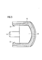
- FIG 3 illustrates a sectional side view of the handle bar 10 for the door handle according to a second embodiment of the present invention.
- the handle bar 10 of the second embodiment comprises additionally at least one pin element 18 and at least one rib 20.
- the handle bar 10 is partially formed as the U-shaped profile part.
- the at least one rib 20 reinforces the handle bar 10.
- the at least one pin element 18 is provided for penetrating into a corresponding hole of the fastening part 12 in order to position the handle bar 10 with respect to said fastening part 12.
- the cross-section of the handle bar 10 comprises two hooks 22 at the open ends of its inner side.
- the hooks 22 extend continuous or in sections along the longitudinal axis of the handle bar 10.
- the hooks 22 and complementary grooves or edges at the fastening part 12 form the snap-in mechanism.
- the door handle according to the present invention comprises a standard basis part and a variable design part.
- the fastening part 12 plays the role of the standard basis part, which can be used for different doors and different domestic appliances, respectively.
- the handle bar 10 plays the role of the variable design part.
- a plurality of different handle parts 10 allows a variation of the design for the doors and the domestic appliances.
- the handle bar 10 can easily be exchanged.
Landscapes
- Engineering & Computer Science (AREA)
- Chemical & Material Sciences (AREA)
- Combustion & Propulsion (AREA)
- Mechanical Engineering (AREA)
- General Engineering & Computer Science (AREA)
- Physics & Mathematics (AREA)
- Thermal Sciences (AREA)
- Electric Ovens (AREA)
- Refrigerator Housings (AREA)
Abstract
The present invention relates to a door handle for a domestic appliance. The door handle includes a handle bar (10) and a fastening part (12). The fastening part (12) is a single-piece part and comprises at least two contact elements (14) and a bracket portion (16). The bracket portion (16) connects the contact elements (14). The contact elements (14) comprise one free side opposite to the bracket portion (16) in each case. The free sides of the contact elements (14) are attached or attachable at a door of the domestic appliance. The bracket portion (16) comprises at least one outer side opposite to the contact elements (14). The handle bar (10) is formed as a profile part with one open longitudinal side. At least one inner side of the profile part of the handle bar (10) is at least partially complementary to the at least one outer side of the bracket portion (16). Further, present invention relates to a domestic appliance with such a door handle.
Description
- The present invention relates to a door handle for a domestic appliance. Further, the present invention relates to a domestic appliance.
- Domestic appliances, like cooking ovens and refrigerators, comprise at least one door handle for opening and closing a corresponding door. Usually the door handle includes a handle part, which can be partially or completely enclosed by the user's hand. A further part of the door handle is provided for fastening said door handle at the door.
-
DE 103 03 734 B4 discloses a door handle for a domestic appliance. The door handle comprises one or two fixing parts and a handle part. The handle part is directly fixed at the one or two fixing parts by form locking connection. -
DE 10 2006 042 176 A1 discloses a door handle for a domestic appliance. The door handle comprises a longitudinal handle part and at least one fixing part. The surfaces of the handle part and the fixing part are made of the same material. -
DE 299 14 024 U1 discloses a door handle for a drawer. The door handle comprises a handle part and a fixing part. Between the transparent handle part and the fixing part an indicating label is arranged. - It is an object of the present invention to provide an improved door handle for a domestic appliance, which door handle is realized by low cost of materials.
- The object of the present invention is achieved by the door handle for a domestic appliance according to claim 1.
- The present invention relates to a door handle for a domestic appliance, wherein:
- the door handle includes a handle bar and a fastening part,
- the fastening part is a single-piece part and comprises at least two contact elements and a bracket portion,
- the bracket portion connects the contact elements,
- the contact elements comprise one free side opposite to the bracket portion in each case,
- the free sides of the contact elements are attached or attachable at a door of the domestic appliance,
- the bracket portion comprises at least one outer side opposite to the contact elements,
- the handle bar is formed as a profile part with one open longitudinal side, and
- at least one inner side of the profile part of the handle bar is at least partially complementary to the at least one outer side of the bracket portion.
- The main idea of the present invention is the door handle with the fastening part, wherein the fastening part is the substantial part of said door handle. The physical properties of the door handle arise from the fastening part. The handle bar is substantially provided for the aesthetic properties of the door handle.
- According to a preferred embodiment of the present invention the handle bar is formed as a U-shaped profile part. The handle bar can be produced as an extruded profile part, wherein any finishing treatment is not required. This contributes to low complexity and low costs.
- In particular, the bracket portion comprises three outer sides opposite to the contact elements. The three outer sides of the bracket portion are provided to be enclosed by the handle bar formed as profile part, in particular form as U-shaped profile part.
- Preferably, the fastening part is made of a material with low heat conductivity. Thus, the door handle can be used at a domestic appliance generating extreme temperatures, like cooking ovens or freezers. The fastening part acts as a thermal isolator, so that the user can touch the door handle without any problems.
- For example, the fastening part is made of plastics. Plastics have low heat conductivity and are low cost materials.
- Further, the handle bar is made of metal or coated by metal. Since the fastening part is made of the material with low heat conductivity, the handle bar may include metal without any problems for the user. The designer has more possibilities for creating the door design.
- For example, the two contact elements are arranged at the both ends of the bracket portion. In this case the fastening part has a typical form for the door handle.
- The handle bar is removable attached or attachable at the bracket portion of the fastening element. This allows an easy exchange of the handle bar.
- In particular, the handle bar is attached or attachable at the bracket portion of the fastening element by a snap-in mechanism.
- Alternatively, the handle bar may be attached or attachable at the bracket portion of the fastening element by a screw joint. Further, the handle bar may be permanently attached or attachable at the bracket portion of the fastening element. In this case, the handle bar may be attached or attachable at the bracket portion of the fastening element by an adhesive joint.
- Preferably, the handle bar comprises at least one centring element corresponding to a complementary element in the bracket portion of the fastening part in order to align the handle bar with the fastening part.
- For example, the at least one centring element is a pin element arranged at least partially within the profile part of the handle bar.
- At last, the present invention relates to a domestic appliance with at least on door, wherein the domestic appliance comprises at least one door handle as described above.
- Novel and inventive features of the present invention are set forth in the appended claims.
- The present invention will be described in further detail with reference to the drawings, in which
- FIG 1
- illustrates a sectional side view of a handle bar and a fastening part for a door handle according to a first embodiment of the present invention,
- FIG 2
- illustrates a perspective view of the handle bar and the fastening part for the door handle according to the first embodiment of the present invention, and
- FIG 3
- illustrates a sectional side view of the handle bar for the door handle according to a second embodiment of the present invention.
-
FIG 1 illustrates a sectional side view of ahandle bar 10 and a fasteningpart 12 for a door handle according to a first embodiment of the present invention. - The door handle is composed of the
handle bar 10 and the fasteningpart 12. In this example, thehandle bar 10 as well as the fasteningpart 12 are formed as single-piece parts in each case. - The
handle bar 10 is formed as a U-shaped profile part. For example, thehandle bar 10 is made of plastics, and the outer side of thehandle bar 10 is coated by metal. Alternatively, thehandle bar 10 is completely made of metal. Further, thehandle bar 10 can be made of ceramics or glass. - The
fastening part 12 includes twocontact elements 14 and alongitudinal bracket portion 16. Thebracket portion 16 connects the bothcontact elements 14. Thebracket portion 16 forms a bridge between the bothcontact elements 14. Thebracket portion 16 comprises an inner long side and three outer long sides. Thecontact elements 14 are attached at the inner long side of thebracket portion 16. In this example, thecontact elements 14 are attached at the both ends of the inner long side of thebracket portion 16. Alternatively, more than twocontact elements 14 may be attached at the inner long side of thebracket portion 16. - The inner sides of the U-shaped profile part of the
handle bar 10 are complementary to the outer long sides of thebracket portion 16. Thus, thehandle bar 10 can attached at thebracket portion 16. Thehandle bar 10 and thebracket portion 16 have the same length, so that thehandle bar 10 covers completely the outer sides of thebracket portion 16. - The
handle bar 10 may be fixed at thebracket portion 16 of thefastening part 12 by a screw joint, a snap-in mechanism and/or an adhesive joint. The snap-in mechanism may act, when thehandle bar 10 is pushed onto thebracket portion 16 of thefastening part 12 perpendicular to the longitudinal axes of thehandle bar 10 and thebracket portion 16. Further, thehandle bar 10 may be pushed onto thebracket portion 16 of thefastening part 12 along the longitudinal axes of thehandle bar 10 and thebracket portion 16. - When the
handle bar 10 is fixed at thebracket portion 16 of thefastening part 12 by the screw joint or the snap-in mechanism, then thehandle bar 10 may be exchanged in an easy way. A fast exchange of thehandle bar 10 is also possible, if thehandle bar 10 is pushed onto thebracket portion 16 of thefastening part 12 along the longitudinal axes of thehandle bar 10 and thebracket portion 16. - If the
fastening part 12 is made of plastics or another material with low heat conductivity, then thefastening part 12 acts as heat insulator. This is advantageous, if the domestic appliance is a cooking oven, a freezer or another apparatus generating extremely high or low temperatures. - In general, the
handle bar 10 as well as thefastening part 12 can be made of plastics, metal, ceramics and/or glass. -
FIG 2 illustrates a perspective view of thehandle bar 10 and thefastening part 12 for the door handle according to the first embodiment of the present invention.FIG 2 clarifies the geometric relationships of thehandle bar 10 and thefastening part 12. - The
handle bar 10, thebracket portion 16 of thefastening part 12 and thefastening part 12 as a whole have the same lengths. Thecontact elements 14 of thefastening part 12 are arranged at the both ends of the inner side of thebracket portion 16. In this example, thecontact elements 14 of thefastening part 12 are substantially block-shaped. -
FIG 3 illustrates a sectional side view of thehandle bar 10 for the door handle according to a second embodiment of the present invention. - The
handle bar 10 of the second embodiment comprises additionally at least onepin element 18 and at least onerib 20. Thehandle bar 10 is partially formed as the U-shaped profile part. The at least onerib 20 reinforces thehandle bar 10. The at least onepin element 18 is provided for penetrating into a corresponding hole of thefastening part 12 in order to position thehandle bar 10 with respect to saidfastening part 12. - Further, the cross-section of the
handle bar 10 comprises twohooks 22 at the open ends of its inner side. Thehooks 22 extend continuous or in sections along the longitudinal axis of thehandle bar 10. Thehooks 22 and complementary grooves or edges at thefastening part 12 form the snap-in mechanism. - The door handle according to the present invention comprises a standard basis part and a variable design part. The
fastening part 12 plays the role of the standard basis part, which can be used for different doors and different domestic appliances, respectively. Thehandle bar 10 plays the role of the variable design part. A plurality ofdifferent handle parts 10 allows a variation of the design for the doors and the domestic appliances. Thehandle bar 10 can easily be exchanged. - Although illustrative embodiments of the present invention have been described herein with reference to the accompanying drawings, it is to be understood that the present invention is not limited to those precise embodiments, and that various other changes and modifications may be affected therein by one skilled in the art without departing from the scope or spirit of the invention. All such changes and modifications are intended to be included within the scope of the invention as defined by the appended claims.
-
- 10
- handle bar
- 12
- fastening part
- 14
- contact element
- 16
- bracket portion
- 18
- pin element
- 20
- rib
- 22
- hook
Claims (15)
- A door handle for a domestic appliance, wherein:- the door handle includes a handle bar (10) and a fastening part (12),- the fastening part (12) is a single-piece part and comprises at least two contact elements (14) and a bracket portion (16),- the bracket portion (16) connects the contact elements (14),- the contact elements (14) comprise one free side opposite to the bracket portion (16) in each case,- the free sides of the contact elements (14) are attached or attachable at a door of the domestic appliance,- the bracket portion (16) comprises at least one outer side opposite to the contact elements (14),- the handle bar (10) is formed as a profile part with one open longitudinal side, and- at least one inner side of the profile part of the handle bar (10) is at least partially complementary to the at least one outer side of the bracket portion (16).
- The door handle according to claim 1,
characterized in, that
the handle bar (10) is formed as a U-shaped profile part. - The door handle according to claim 1 or 2,
characterized in, that
the bracket portion (16) comprises three outer sides opposite to the contact elements (14). - The door handle according to any one of the preceding claims, characterized in, that
the fastening part (12) is made of a material with low heat conductivity. - The door handle according to claim 4,
characterized in, that
the fastening part (12) is made of plastics. - The door handle according to any one of the preceding claims, characterized in, that
the handle bar (10) is made of metal or coated by metal. - The door handle according to any one of the preceding claims, characterized in, that
the two contact elements (14) are arranged at the both ends of the bracket portion (16). - The door handle according to any one of the preceding claims, characterized in, that
the handle bar (10) is removable attached or attachable at the bracket portion (16) of the fastening element (12). - The door handle according to claim 8,
characterized in, that
the handle bar (10) is attached or attachable at the bracket portion (16) of the fastening element (12) by a snap-in mechanism (22). - The door handle according to claim 8,
characterized in, that
the handle bar (10) is attached or attachable at the bracket portion (16) of the fastening element (12) by a screw joint. - The door handle according to any one of the preceding claims, characterized in, that
the handle bar (10) is permanently attached or attachable at the bracket portion (16) of the fastening element (12). - The door handle according to claim 11,
characterized in, that
the handle bar (10) is attached or attachable at the bracket portion (16) of the fastening element (12) by an adhesive joint. - The door handle according to any one of the preceding claims, characterized in, that
the handle bar (10) comprises at least one centring element (18) corresponding to a complementary element of the fastening part (12) in order to align the handle bar (10) with the fastening part (12). - The door handle according to claim 13,
characterized in, that
the at least one centring element is a pin element (18) arranged at least partially within the profile part of the handle bar (10). - A domestic appliance with at least on door,
characterized in, that
the domestic appliance comprises at least one door handle according to any one of the claims 1 to 14.
Priority Applications (7)
| Application Number | Priority Date | Filing Date | Title |
|---|---|---|---|
| EP10005102A EP2386701A1 (en) | 2010-05-14 | 2010-05-14 | A door handle for a domestic appliance |
| EP11001200A EP2386702A1 (en) | 2010-05-14 | 2011-02-15 | A door handle for a domestic appliance |
| BR112012028807A BR112012028807A2 (en) | 2010-05-14 | 2011-05-13 | door handle for a household appliance |
| PCT/EP2011/002377 WO2011141181A1 (en) | 2010-05-14 | 2011-05-13 | A door handle for a domestic appliance |
| US13/639,889 US20130125345A1 (en) | 2010-05-14 | 2011-05-13 | Door handle for a domestic appliance |
| AU2011252338A AU2011252338A1 (en) | 2010-05-14 | 2011-05-13 | A door handle for a domestic appliance |
| CN2011800210771A CN102906359A (en) | 2010-05-14 | 2011-05-13 | A door handle for a domestic appliance |
Applications Claiming Priority (1)
| Application Number | Priority Date | Filing Date | Title |
|---|---|---|---|
| EP10005102A EP2386701A1 (en) | 2010-05-14 | 2010-05-14 | A door handle for a domestic appliance |
Publications (1)
| Publication Number | Publication Date |
|---|---|
| EP2386701A1 true EP2386701A1 (en) | 2011-11-16 |
Family
ID=42931994
Family Applications (2)
| Application Number | Title | Priority Date | Filing Date |
|---|---|---|---|
| EP10005102A Withdrawn EP2386701A1 (en) | 2010-05-14 | 2010-05-14 | A door handle for a domestic appliance |
| EP11001200A Withdrawn EP2386702A1 (en) | 2010-05-14 | 2011-02-15 | A door handle for a domestic appliance |
Family Applications After (1)
| Application Number | Title | Priority Date | Filing Date |
|---|---|---|---|
| EP11001200A Withdrawn EP2386702A1 (en) | 2010-05-14 | 2011-02-15 | A door handle for a domestic appliance |
Country Status (6)
| Country | Link |
|---|---|
| US (1) | US20130125345A1 (en) |
| EP (2) | EP2386701A1 (en) |
| CN (1) | CN102906359A (en) |
| AU (1) | AU2011252338A1 (en) |
| BR (1) | BR112012028807A2 (en) |
| WO (1) | WO2011141181A1 (en) |
Cited By (2)
| Publication number | Priority date | Publication date | Assignee | Title |
|---|---|---|---|---|
| WO2014090668A1 (en) * | 2012-12-11 | 2014-06-19 | BSH Bosch und Siemens Hausgeräte GmbH | Domestic refrigeration appliance comprising a gripping device |
| CN106930603A (en) * | 2015-12-31 | 2017-07-07 | 博西华电器(江苏)有限公司 | Refrigerator |
Families Citing this family (18)
| Publication number | Priority date | Publication date | Assignee | Title |
|---|---|---|---|---|
| US9194156B2 (en) * | 2013-05-23 | 2015-11-24 | Triangle Brass Manufacturing Company, Inc. | Cover trim for a push bar of an exit device |
| CN103266809A (en) * | 2013-06-13 | 2013-08-28 | 苏州新区华士达工程塑胶有限公司 | High-temperature-resistant plastic fire control doorknob |
| USD729035S1 (en) * | 2014-06-05 | 2015-05-12 | Top Knobs USA, Inc. | Cabinet handle |
| CN105333680B (en) * | 2014-07-18 | 2019-02-26 | 博西华电器(江苏)有限公司 | refrigerator |
| CN105258438B (en) * | 2014-07-18 | 2019-06-25 | 博西华电器(江苏)有限公司 | refrigerator with handle slot |
| CN105003122B (en) * | 2015-07-30 | 2018-08-28 | 合肥华凌股份有限公司 | A kind of boosting handle structure and refrigerator |
| US10781607B2 (en) * | 2018-03-12 | 2020-09-22 | C&D Zodiac, Inc. | Handle load transfer insert for panels |
| US10787839B2 (en) * | 2018-07-09 | 2020-09-29 | Neo Design, LLC | Snap-on cover for vehicle door handle |
| DK180889B1 (en) * | 2020-02-14 | 2022-06-14 | Rehau Behr As | Glass door with a handle device |
| USD1053694S1 (en) * | 2020-03-17 | 2024-12-10 | Bradley Company, LLC | Grab bar |
| US11046257B1 (en) * | 2020-07-02 | 2021-06-29 | Neo Design, LLC | Snap-on automotive grille overlay with complete surround and method for manufacturing the same |
| US11248835B1 (en) | 2020-11-04 | 2022-02-15 | Haier Us Appliance Solutions, Inc. | Quick release handle including lights and sound |
| USD981204S1 (en) * | 2021-11-02 | 2023-03-21 | Apparatus Llc | Fluted handle |
| CN117306950B (en) * | 2022-06-21 | 2026-04-28 | 广东美的厨房电器制造有限公司 | A door handle, door assembly, and cooking equipment |
| US12256843B2 (en) | 2022-06-23 | 2025-03-25 | Morgan Uhl | Decorative knob cover |
| CN220580739U (en) * | 2023-07-26 | 2024-03-12 | 广东美的厨房电器制造有限公司 | Handle components, door components and cooking equipment |
| US20250122747A1 (en) * | 2023-10-11 | 2025-04-17 | Morgan Uhl | Decorative cabinet door and drawer handle surround |
| USD1092176S1 (en) * | 2023-10-11 | 2025-09-09 | Morgan Uhl | Cabinet handle cover |
Citations (8)
| Publication number | Priority date | Publication date | Assignee | Title |
|---|---|---|---|---|
| US3766598A (en) * | 1971-10-12 | 1973-10-23 | Gen Electric | Handle assembly |
| US4087141A (en) * | 1976-09-03 | 1978-05-02 | General Electric Company | Door pull handle assembly |
| US5659927A (en) * | 1994-12-12 | 1997-08-26 | Silvatrim Associates | Refrigerator door handle |
| DE29914024U1 (en) | 1999-08-11 | 1999-10-28 | Union Knopf GmbH, 33689 Bielefeld | Organizational grip |
| US20050285491A1 (en) * | 2004-05-20 | 2005-12-29 | Lee Jae H | Door assembly for use in a home appliance |
| DE102006042176A1 (en) | 2006-09-08 | 2008-03-27 | BSH Bosch und Siemens Hausgeräte GmbH | Handle for a household appliance |
| DE10303734B4 (en) | 2003-01-30 | 2009-05-07 | BSH Bosch und Siemens Hausgeräte GmbH | Handle for a household appliance |
| EP2100538A1 (en) * | 2008-03-10 | 2009-09-16 | Giusti Spa | Handle with exchangeable cover |
Family Cites Families (8)
| Publication number | Priority date | Publication date | Assignee | Title |
|---|---|---|---|---|
| US6826804B2 (en) * | 2002-08-30 | 2004-12-07 | Palliser Furniture Ltd. | Furniture handle |
| US7861380B2 (en) * | 2004-05-07 | 2011-01-04 | Tubular Fabricators Industry, Inc. | Replaceable hand grip |
| US7249395B2 (en) * | 2004-10-26 | 2007-07-31 | Stromberg-Carlson Products, Inc. | Hand bracket |
| AU2006288046B2 (en) * | 2005-09-07 | 2011-02-17 | Lg Electronics Inc. | Door handle for refrigerator |
| KR20080065434A (en) * | 2007-01-09 | 2008-07-14 | 엘지전자 주식회사 | Refrigerator Door Handle |
| CN101946143B (en) * | 2008-02-21 | 2012-12-26 | Lg电子株式会社 | Refrigerator, refrigerator door handle, and assembling method of the refrigerator door handle |
| US8215731B2 (en) * | 2008-07-09 | 2012-07-10 | Whirlpool Corporation | Handle assembly for a domestic appliance |
| US20100037433A1 (en) * | 2008-08-13 | 2010-02-18 | Brett Clyde Walker | Handle for exercise equipment incorporating a feature for adjusting length of an attached cord |
-
2010
- 2010-05-14 EP EP10005102A patent/EP2386701A1/en not_active Withdrawn
-
2011
- 2011-02-15 EP EP11001200A patent/EP2386702A1/en not_active Withdrawn
- 2011-05-13 AU AU2011252338A patent/AU2011252338A1/en not_active Abandoned
- 2011-05-13 CN CN2011800210771A patent/CN102906359A/en active Pending
- 2011-05-13 BR BR112012028807A patent/BR112012028807A2/en not_active IP Right Cessation
- 2011-05-13 WO PCT/EP2011/002377 patent/WO2011141181A1/en not_active Ceased
- 2011-05-13 US US13/639,889 patent/US20130125345A1/en not_active Abandoned
Patent Citations (8)
| Publication number | Priority date | Publication date | Assignee | Title |
|---|---|---|---|---|
| US3766598A (en) * | 1971-10-12 | 1973-10-23 | Gen Electric | Handle assembly |
| US4087141A (en) * | 1976-09-03 | 1978-05-02 | General Electric Company | Door pull handle assembly |
| US5659927A (en) * | 1994-12-12 | 1997-08-26 | Silvatrim Associates | Refrigerator door handle |
| DE29914024U1 (en) | 1999-08-11 | 1999-10-28 | Union Knopf GmbH, 33689 Bielefeld | Organizational grip |
| DE10303734B4 (en) | 2003-01-30 | 2009-05-07 | BSH Bosch und Siemens Hausgeräte GmbH | Handle for a household appliance |
| US20050285491A1 (en) * | 2004-05-20 | 2005-12-29 | Lee Jae H | Door assembly for use in a home appliance |
| DE102006042176A1 (en) | 2006-09-08 | 2008-03-27 | BSH Bosch und Siemens Hausgeräte GmbH | Handle for a household appliance |
| EP2100538A1 (en) * | 2008-03-10 | 2009-09-16 | Giusti Spa | Handle with exchangeable cover |
Cited By (3)
| Publication number | Priority date | Publication date | Assignee | Title |
|---|---|---|---|---|
| WO2014090668A1 (en) * | 2012-12-11 | 2014-06-19 | BSH Bosch und Siemens Hausgeräte GmbH | Domestic refrigeration appliance comprising a gripping device |
| ES2543277R1 (en) * | 2012-12-11 | 2015-08-25 | Bsh Hausgeráte Gmbh | DOMESTIC REFRIGERATION APPLIANCE WITH AN AGARRE DEVICE |
| CN106930603A (en) * | 2015-12-31 | 2017-07-07 | 博西华电器(江苏)有限公司 | Refrigerator |
Also Published As
| Publication number | Publication date |
|---|---|
| CN102906359A (en) | 2013-01-30 |
| BR112012028807A2 (en) | 2016-07-26 |
| AU2011252338A1 (en) | 2012-12-20 |
| WO2011141181A1 (en) | 2011-11-17 |
| EP2386702A1 (en) | 2011-11-16 |
| US20130125345A1 (en) | 2013-05-23 |
Similar Documents
| Publication | Publication Date | Title |
|---|---|---|
| EP2386702A1 (en) | A door handle for a domestic appliance | |
| EP2949179B1 (en) | An oven door and a chassis for a microwave oven or an appliance with microwave heating function | |
| USD626782S1 (en) | Oven, microwave, warming drawer, cooktop, and/or cooking appliance | |
| CN102893092B (en) | A door for a domestic appliance | |
| EP3443269B1 (en) | Domestic appliance with a cable tube between a door and a chassis of the appliance | |
| US20100283364A1 (en) | Auto-racks | |
| EP2108892B1 (en) | Built-in oven | |
| EP2868981A1 (en) | A door for a domestic appliance | |
| US20190049120A1 (en) | Accessory support part for a household cooking appliance | |
| US9016270B2 (en) | Window mounting for thermal expansion in an oven appliance | |
| US20220357046A1 (en) | Twist release mechanism for a multi-pane door assembly | |
| CN103443568B (en) | Refrigeration appliance door | |
| EP3118525B1 (en) | Oven door for an oven cavity of a cooking oven | |
| EP2798136B1 (en) | A household appliance | |
| EP3327378A1 (en) | Home appliance device | |
| US10480796B2 (en) | Handle for a rack support structure | |
| US9732965B2 (en) | Baking appliance | |
| EP3040660B1 (en) | Door handle for a furniture unit, in particular a refrigerator | |
| GB2510845A (en) | Improved Composite Profile for a Door or Window Frame | |
| EP3340739B1 (en) | Oven door for a microwave oven | |
| CN104302994B (en) | Household electrical appliance including handle | |
| EP3130871B1 (en) | A household appliance comprising a handle | |
| KR100700769B1 (en) | Internal glass mounting structure of oven door | |
| EP4293286A1 (en) | Detachable and interchangeable appliance handle | |
| KR100563346B1 (en) | Refrigerator door handles |
Legal Events
| Date | Code | Title | Description |
|---|---|---|---|
| 17P | Request for examination filed |
Effective date: 20110420 |
|
| AK | Designated contracting states |
Kind code of ref document: A1 Designated state(s): AL AT BE BG CH CY CZ DE DK EE ES FI FR GB GR HR HU IE IS IT LI LT LU LV MC MK MT NL NO PL PT RO SE SI SK SM TR |
|
| AX | Request for extension of the european patent |
Extension state: BA ME RS |
|
| PUAI | Public reference made under article 153(3) epc to a published international application that has entered the european phase |
Free format text: ORIGINAL CODE: 0009012 |
|
| STAA | Information on the status of an ep patent application or granted ep patent |
Free format text: STATUS: THE APPLICATION IS DEEMED TO BE WITHDRAWN |
|
| 18D | Application deemed to be withdrawn |
Effective date: 20141202 |