EP2386678B1 - Closed cycle dryer and process for drying clothes using such dryer - Google Patents
Closed cycle dryer and process for drying clothes using such dryer Download PDFInfo
- Publication number
- EP2386678B1 EP2386678B1 EP10162431.0A EP10162431A EP2386678B1 EP 2386678 B1 EP2386678 B1 EP 2386678B1 EP 10162431 A EP10162431 A EP 10162431A EP 2386678 B1 EP2386678 B1 EP 2386678B1
- Authority
- EP
- European Patent Office
- Prior art keywords
- air
- drum
- closed cycle
- unit
- dryer
- Prior art date
- Legal status (The legal status is an assumption and is not a legal conclusion. Google has not performed a legal analysis and makes no representation as to the accuracy of the status listed.)
- Active
Links
Images


Classifications
-
- D—TEXTILES; PAPER
- D06—TREATMENT OF TEXTILES OR THE LIKE; LAUNDERING; FLEXIBLE MATERIALS NOT OTHERWISE PROVIDED FOR
- D06F—LAUNDERING, DRYING, IRONING, PRESSING OR FOLDING TEXTILE ARTICLES
- D06F58/00—Domestic laundry dryers
- D06F58/20—General details of domestic laundry dryers
-
- D—TEXTILES; PAPER
- D06—TREATMENT OF TEXTILES OR THE LIKE; LAUNDERING; FLEXIBLE MATERIALS NOT OTHERWISE PROVIDED FOR
- D06F—LAUNDERING, DRYING, IRONING, PRESSING OR FOLDING TEXTILE ARTICLES
- D06F58/00—Domestic laundry dryers
- D06F58/30—Drying processes
-
- D—TEXTILES; PAPER
- D06—TREATMENT OF TEXTILES OR THE LIKE; LAUNDERING; FLEXIBLE MATERIALS NOT OTHERWISE PROVIDED FOR
- D06F—LAUNDERING, DRYING, IRONING, PRESSING OR FOLDING TEXTILE ARTICLES
- D06F58/00—Domestic laundry dryers
- D06F58/10—Drying cabinets or drying chambers having heating or ventilating means
-
- D—TEXTILES; PAPER
- D06—TREATMENT OF TEXTILES OR THE LIKE; LAUNDERING; FLEXIBLE MATERIALS NOT OTHERWISE PROVIDED FOR
- D06F—LAUNDERING, DRYING, IRONING, PRESSING OR FOLDING TEXTILE ARTICLES
- D06F58/00—Domestic laundry dryers
- D06F58/20—General details of domestic laundry dryers
- D06F58/24—Condensing arrangements
Definitions
- the present invention relates to a closed cycle dryer comprising a drum, an air blowing unit whereby the air is conveyed to the drum, a heating unit used to heat air that is blown into the drum, and a condensing unit placed upstream the heating unit for removing moisture.
- the invention relates also to a process for drying clothes in a closed cycle dryer.
- DE 3446468 A1 discloses a drying apparatus according to the preamble of the attached claim 1.
- DE 3204718 A1 discloses a drying apparatus comprising a drying chamber connected in an air circulation circuit which has a branch loop outside the chamber.
- a refrigeration cycle can be used in which the evaporator is used as a condenser for the drying cycle and the condenser of the refrigeration cycle is used as a heating unit.
- the condensing unit is provided with water nozzles which cool air and help to remove fluff.
- One of the main features of the present invention is the use of a by-pass or short cut which creates a direct link between the outlet of the condensing unit and the outlet of the drum upstream the inlet of the blower.
- the outlet of the by-pass conduit may be placed downstream the filter housing.
- the by-pass conduit enables a predetermined part of the process air which has already passed the condensing unit (and is saturated with moisture) to be mixed with the hot and humid air coming from the drum with tumbling clothes (which is not completely saturated with moisture).
- the by-pass conduit can be a simple tube that links outlet of the blower downstream the condensing unit and the outlet of the drum or inlet of the blower. Both air flows (from the drum and from the by-pass conduit) will be mixed and will enter the condensing unit more saturated and pre-cooled than without the by-pass.
- the unexpected main advantage deriving from the solution according to the present invention is that the energy needed for reaching the 100% humidity line (condensing line) in the Mollier diagram where condensation takes place is reduced if compared to a traditional drying cycle.
- the cooling power of the condensing unit is used more efficiently for the condensation (latent heat/ phase change) itself.
- Another advantage of the solution according to the present invention is that a part of the process air flow that passes through the by pass conduit reduces the overall resistance that the air blower has to overcome. This leads to higher air flow through the blower and so through the condensing unit as well.
- a drum of a clothes dryer using a closed cycle The drum 10 is fed in 10a with hot air heated by a heater 12 in which a heating power Q h is transferred to air.
- the flow of air is driven by a blower 14. Downstream the blower 14 and upstream the heater 12, the dryer is provided with a condensing unit 16 for removing humidity (and heat) from the air flow.
- the cooling power of the condensing unit 16 is identified with reference Q c .
- the humid air is flowing in 10b from the drum 10 and passes through a filter 18 for removing fluff, before reaching the blower 14.
- the condensing unit 16 could be placed upstream the blower 14 as well (solution not shown in the drawings).
- the air circuit of the dryer is provided with a by-pass conduit 20 interposed between, on one side, a portion 22 of the circuit downstream the condensing unit 16 and the heater 12 and, on the other side, a portion 24 of the circuit downstream the filter 18 and upstream the blower 14.
- Line T of the diagram shows the situation inside the drum 10, where energy is transferred from hot air to clothes and therefore to water contained therein for its evaporation (nearly constant enthalpy).
- temperature of air from inlet 10a to outlet 10b is going down, and at the drum outlet 10b air is saturated at around 80% with water.
- Point M1 shows the thermodynamic state of air before being mixed at portion 24 of the circuit. Such air M1 is mixed with air coming out from the condensing unit 16 (point K in figure 3 ).
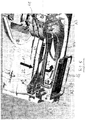
- FIG. 4 shows a preferred embodiment for a dryer having a condensing unit 16 placed at the bottom of the dryer housing and in which the by-pass conduit 20 is defined by a shaped portion of the housing in which the blower 14 is installed, and particularly in which the by-pass is defined by an opening 22 in the housing of the condensing unit 16.
- Figure 5 shows an enlarged structural detail of figure 4 , where the same references used for figure 1 have been used.
- Arrows A1 shows the air coming from the drum.
- the hot and unsaturated flow A1 is mixed with cold and saturated flow A2 from the opening 22 in the condenser housing.
- the mixed flow A3 (combination of flows A1 and A2) passes through the blower 14 and the condensing unit and it is split in a primary air flow A4 to the heater and in the by-pass flow A2 to the blower.
- the solution according to figure 5 is particularly efficient since, in order to create a by-pass conduit, it is only necessary to open a part of the condensing unit housing close to the inlet of the blower.
Description
- The present invention relates to a closed cycle dryer comprising a drum, an air blowing unit whereby the air is conveyed to the drum, a heating unit used to heat air that is blown into the drum, and a condensing unit placed upstream the heating unit for removing moisture. The invention relates also to a process for drying clothes in a closed cycle dryer.
- In the closed cycle dryers the air that receives moisture from the clothes is transferred to a condenser where moisture is removed, and then, after being heated, is supplied back to the drum.
DE 3446468 A1 discloses a drying apparatus according to the preamble of the attachedclaim 1.DE 3204718 A1 discloses a drying apparatus comprising a drying chamber connected in an air circulation circuit which has a branch loop outside the chamber. - Various solutions have been developed in order to improve the efficiency of the dryers using a closed cycle. For instance, a refrigeration cycle can be used in which the evaporator is used as a condenser for the drying cycle and the condenser of the refrigeration cycle is used as a heating unit. In another solution the condensing unit is provided with water nozzles which cool air and help to remove fluff. Of course these solutions, even if they increase the overall efficiency of the drying process, increase the complexity (and therefore the overall cost) of the dryer.
- It is an object of the present invention to provide a dryer with an improved condensation efficiency thanks to a simple and not expensive modification of the air path in the machine.
- Such object is reached thanks to the features listed in the appended claims. One of the main features of the present invention is the use of a by-pass or short cut which creates a direct link between the outlet of the condensing unit and the outlet of the drum upstream the inlet of the blower. Where a filter is used for removing fluff downstream the drum, the outlet of the by-pass conduit may be placed downstream the filter housing.
- According to the invention, the by-pass conduit enables a predetermined part of the process air which has already passed the condensing unit (and is saturated with moisture) to be mixed with the hot and humid air coming from the drum with tumbling clothes (which is not completely saturated with moisture).
- According to an embodiment of the invention, the by-pass conduit can be a simple tube that links outlet of the blower downstream the condensing unit and the outlet of the drum or inlet of the blower. Both air flows (from the drum and from the by-pass conduit) will be mixed and will enter the condensing unit more saturated and pre-cooled than without the by-pass.
- The unexpected main advantage deriving from the solution according to the present invention is that the energy needed for reaching the 100% humidity line (condensing line) in the Mollier diagram where condensation takes place is reduced if compared to a traditional drying cycle.
- Less sensible heat (which would lead to energy losses) needs to be transferred to start condensation. The cooling power of the condensing unit is used more efficiently for the condensation (latent heat/ phase change) itself.
- Another advantage of the solution according to the present invention is that a part of the process air flow that passes through the by pass conduit reduces the overall resistance that the air blower has to overcome. This leads to higher air flow through the blower and so through the condensing unit as well.
- Higher volume flow through the condensing unit, particularly in case a heat exchanger with plates is used, leads to better heat transfer and to higher condensation efficiency. Tests carried out by the applicant have shown an increased process air flow through blower and condensing unit of 10 % and above. With the by-pass the overall energy consumption is reduced. According to the result of the above tests, the energy saving is higher than 0,01 kWh/kg dry laundry.
- Further features and advantages of a dryer according to the present invention will be clear from the following detailed description, with reference to the attached drawings in which:
-
figure 1 is a schematic view of a closed cycle dryer according to the invention; -
figure 2 is a drying cycle according to prior art on a Mollier diagram; -
figure 3 is similar tofigure 2 and shows the drying cycle according to the present invention; -
figure 4 is a schematic view of a closed cycle dryer with a preferred air path according to the invention; and -
figure 5 is a partial and more detailed view of a dryer according tofigure 4. - With reference to the drawings, with 10 it is indicated a drum of a clothes dryer using a closed cycle. The
drum 10 is fed in 10a with hot air heated by aheater 12 in which a heating power Qh is transferred to air. The flow of air is driven by ablower 14. Downstream theblower 14 and upstream theheater 12, the dryer is provided with acondensing unit 16 for removing humidity (and heat) from the air flow. The cooling power of thecondensing unit 16 is identified with reference Qc. The humid air is flowing in 10b from thedrum 10 and passes through afilter 18 for removing fluff, before reaching theblower 14. Thecondensing unit 16 could be placed upstream theblower 14 as well (solution not shown in the drawings). - According to the invention, the air circuit of the dryer is provided with a by-
pass conduit 20 interposed between, on one side, aportion 22 of the circuit downstream thecondensing unit 16 and theheater 12 and, on the other side, aportion 24 of the circuit downstream thefilter 18 and upstream theblower 14. - In the dryer according to prior art, i.e. without the by-
pass conduit 20, the drying process is shown infigure 2 . Unsaturated air enters the condensing unit at point C of the Mollier diagram. To cool down the air to the condensing line (indicated with reference W infigure 2 - 100% relative humidity) a certain cooling power is needed. Such cooling power is shown by the line identified with reference number 3 infigure 2 . After cooling in the condensing unit, air needs to be heated up and this leads to further energy consumption. To cool the process air by 1°C of to heat up such air by 1°C a power of around 50 W is needed. - The process according to the invention, i.e. with the by-
pass conduit 20, is shown infigure 3 . Line T of the diagram shows the situation inside thedrum 10, where energy is transferred from hot air to clothes and therefore to water contained therein for its evaporation (nearly constant enthalpy). In thedrum 10 temperature of air from inlet 10a to outlet 10b is going down, and at the drum outlet 10b air is saturated at around 80% with water. Point M1 shows the thermodynamic state of air before being mixed atportion 24 of the circuit. Such air M1 is mixed with air coming out from the condensing unit 16 (point K infigure 3 ). Such mixture changes the state of air along lines 4 and 4' so that the final result of the mixture is air at point M2 with a lower enthalpy than M1. It is therefore clear that for further cooling such air (line 3 infigure 3 ), a lower amount of energy is needed for reaching line W if compared to prior art. This is due to the fact that the mixture of process air (M2) is more saturated and pre-cooled when entering thecondensing unit 16. The power saving is comprised between 50 and 100 W. Line H offigure 3 shows the heating phase in theheater 12, where absolute humidity remains constant and where relative humidity at the outlet from theheating element 12 is below 15%. - Instead of mixing the two flows of air downstream the
filter 18, such mixing can be advantageously carried out in the filter housing (embodiment shown in dotted line infigure 1 ), and this leads to a slightly reduced temperature in filter which increase the filtration efficiency. Thefilter 18 may also be placed downstream theportion 24 of the circuit where the by-pass conduit 20 flows in the main air circulation conduit (embodiment shown in dotted line, lower right part offigure 1 ).Figure 4 shows a preferred embodiment for a dryer having acondensing unit 16 placed at the bottom of the dryer housing and in which the by-pass conduit 20 is defined by a shaped portion of the housing in which theblower 14 is installed, and particularly in which the by-pass is defined by anopening 22 in the housing of thecondensing unit 16. -
Figure 5 shows an enlarged structural detail offigure 4 , where the same references used forfigure 1 have been used. Arrows A1 shows the air coming from the drum. The hot and unsaturated flow A1 is mixed with cold and saturated flow A2 from the opening 22 in the condenser housing. The mixed flow A3 (combination of flows A1 and A2) passes through theblower 14 and the condensing unit and it is split in a primary air flow A4 to the heater and in the by-pass flow A2 to the blower. The solution according tofigure 5 is particularly efficient since, in order to create a by-pass conduit, it is only necessary to open a part of the condensing unit housing close to the inlet of the blower. - Good results in terms of overall energy efficiency have been obtained with a total air flow through the blower comprised between 210 m3/h and 250 m3/h, preferably between 220 m3/h and 240 m3/h, with a fraction of the air flow diverted in the by-pass comprised between 10% and 20%, preferably around 15%.
- The following table shows a comparison between the air flows in a closed cycle dryer according to the prior art and according to the invention:
Without by-pass m3/h With by-pass m3/h With by-pass Complete process air loop 210 200 -5% Flow through by- pass 0 30 15% Flow through condensing unit and blower 210 230 110%
Claims (11)
- A closed cycle dryer comprising a drum (10), an air blowing unit (14) whereby the air is conveyed to the drum (10), a heating unit (12) used to heat the air that is blown into the drum, and a condensing unit (16) downstream the air blowing unit (14) and upstream the heating unit (12) for removing moisture, a by-pass (20) being comprised between a first portion (22) of the air circuit downstream the condensing unit (16) and upstream the heating unit (12) and a second portion (24) downstream the drum (10), characterized in that the second portion (24) of the air circuit is upstream the air blowing unit (14).
- A closed cycle dryer according to claim 1, wherein the first portion (22) of the air circuit is upstream the heating unit (12).
- A closed cycle dryer according to claim 1 or 2, wherein a filter (18) is placed in the second portion (24) of the air circuit where there is a mixture of air from the drum (10) and from the by-pass (20).
- A closed cycle dryer according to any of the preceding claims, wherein the by-pass (20) is defined by an opening (22) of the condensing unit housing.
- A closed cycle dryer according to claim 4, wherein the opening (22) of the condensing unit housing is close to the inlet of the blowing unit (14).
- A closed cycle dryer according to claim 4 or 5, wherein the condensing unit (16) is placed at the bottom of a housing of the dryer.
- A closed cycle dryer according to any of the preceding claims, wherein the by-pass flow is comprised between 10% and 20% of the total air flow.
- A closed cycle dryer according to any of the preceding claims, wherein the condensing unit (16) is placed downstream the air blowing unit (14).
- Process for drying clothes in a closed cycle dryer comprising a drum (10), an air blowing unit (14) whereby the air is conveyed to the drum (10), a heating unit (12) used to heat the air that is blown into the drum, and a condensing unit (16) upstream the heating unit (12) for removing moisture, characterized in that a predetermined fraction of the air flow is conveyed in a by-pass (20) between a first portion (22) of the air circuit downstream the condensing unit (16) and upstream the heating unit (12) and a second portion (24) downstream the drum (10), wherein the second portion (24) of the air circuit is upstream the air blowing unit (14).
- Process according to claim 9, wherein the first portion (22) of the air circuit is upstream the heating unit (12).
- Process according to any of claims 9-10, wherein the fraction of the air flow conveyed in the by-pass (20) is comprised between 10% and 20% of the total air flow.
Priority Applications (3)
| Application Number | Priority Date | Filing Date | Title |
|---|---|---|---|
| PL10162431T PL2386678T3 (en) | 2010-05-10 | 2010-05-10 | Closed cycle dryer and process for drying clothes using such dryer |
| EP10162431.0A EP2386678B1 (en) | 2010-05-10 | 2010-05-10 | Closed cycle dryer and process for drying clothes using such dryer |
| US13/100,326 US8793899B2 (en) | 2010-05-10 | 2011-05-04 | Closed cycle dryer and process for drying clothes using such dryer |
Applications Claiming Priority (1)
| Application Number | Priority Date | Filing Date | Title |
|---|---|---|---|
| EP10162431.0A EP2386678B1 (en) | 2010-05-10 | 2010-05-10 | Closed cycle dryer and process for drying clothes using such dryer |
Publications (2)
| Publication Number | Publication Date |
|---|---|
| EP2386678A1 EP2386678A1 (en) | 2011-11-16 |
| EP2386678B1 true EP2386678B1 (en) | 2016-11-30 |
Family
ID=43031467
Family Applications (1)
| Application Number | Title | Priority Date | Filing Date |
|---|---|---|---|
| EP10162431.0A Active EP2386678B1 (en) | 2010-05-10 | 2010-05-10 | Closed cycle dryer and process for drying clothes using such dryer |
Country Status (3)
| Country | Link |
|---|---|
| US (1) | US8793899B2 (en) |
| EP (1) | EP2386678B1 (en) |
| PL (1) | PL2386678T3 (en) |
Families Citing this family (10)
| Publication number | Priority date | Publication date | Assignee | Title |
|---|---|---|---|---|
| EP2475885A4 (en) * | 2009-09-13 | 2013-12-11 | US Solar Holdings LLC | Systems and methods of thermal energy storage and release |
| PL2386678T3 (en) * | 2010-05-10 | 2017-04-28 | Whirlpool Corporation | Closed cycle dryer and process for drying clothes using such dryer |
| DE102012008193A1 (en) * | 2012-04-26 | 2013-10-31 | Herbert Kannegiesser Gmbh | Method for drying laundry items |
| CN103015140A (en) * | 2012-12-21 | 2013-04-03 | 无锡小天鹅股份有限公司 | Clothes dryer |
| EP2789728B1 (en) * | 2013-04-08 | 2017-06-28 | Electrolux Appliances Aktiebolag | Method for controlling a motor of a laundry dryer |
| WO2015078526A1 (en) * | 2013-11-29 | 2015-06-04 | Arcelik Anonim Sirketi | Laundry treatment appliance with a compressor cooling line in parallel with processing air line |
| US10236800B2 (en) | 2014-06-30 | 2019-03-19 | Nidec Motor Corporation | Electronically controlled switch for an electric motor |
| WO2016003824A1 (en) * | 2014-06-30 | 2016-01-07 | Nidec Motor Corporation | Electronically controlled switch for an electric motor |
| US10480117B2 (en) * | 2017-02-27 | 2019-11-19 | Whirlpool Corporation | Self cleaning sump cover |
| CN110887343A (en) * | 2019-11-07 | 2020-03-17 | 湖南工业大学 | High-frequency-based wood powder drying device and process thereof |
Citations (1)
| Publication number | Priority date | Publication date | Assignee | Title |
|---|---|---|---|---|
| DE3446468A1 (en) * | 1984-12-20 | 1986-07-03 | Licentia Patent-Verwaltungs-Gmbh, 6000 Frankfurt | Process and apparatus for the drying of laundry |
Family Cites Families (17)
| Publication number | Priority date | Publication date | Assignee | Title |
|---|---|---|---|---|
| US3234660A (en) * | 1962-08-08 | 1966-02-15 | Whirlpool Co | Dry control apparatus and circuitry for a dry cleaner |
| US3196553A (en) * | 1960-09-19 | 1965-07-27 | Gen Motors Corp | Temperature responsive timer control for a clothes drier |
| US3273256A (en) * | 1964-11-02 | 1966-09-20 | Borg Warner | Dry cleaning machine |
| US3739487A (en) * | 1971-01-28 | 1973-06-19 | R Clark | Drying apparatus |
| DE2531265A1 (en) | 1975-07-12 | 1977-01-27 | Licentia Gmbh | Washing and spinning machine with inflatable packing - allowing packing to be mounted permanently and operated by unskilled persons |
| GB2094961B (en) * | 1981-02-13 | 1984-09-26 | Perlino Antonio | Drying apparatus |
| US4603489A (en) * | 1984-10-05 | 1986-08-05 | Michael Goldberg | Heat pump closed loop drying |
| DE3446568A1 (en) * | 1984-12-20 | 1986-07-10 | Bosch-Siemens Hausgeräte GmbH, 7000 Stuttgart | Method for mounting an elastic hose on a stiff pipe nozzle |
| DE68925469T2 (en) * | 1988-11-30 | 1996-05-30 | Mitsubishi Heavy Ind Ltd | Process for recovering the solvent from a dry cleaning apparatus |
| IT1246211B (en) * | 1990-10-18 | 1994-11-16 | Eurodomestici Ind Riunite | METHOD AND EQUIPMENT TO CONTROL THE DRYING PHASE IN A DRYER, WASHING MACHINE OR SIMILAR MACHINE. |
| DK0999302T3 (en) * | 1998-10-21 | 2003-12-01 | Whirlpool Co | Dryer with a heat pump |
| JP4521297B2 (en) * | 2005-02-22 | 2010-08-11 | 株式会社東芝 | Drum type washer / dryer |
| US7526879B2 (en) * | 2005-11-04 | 2009-05-05 | Lg Electronics Inc. | Drum washing machine and clothes dryer using peltier thermoelectric module |
| JP4020949B1 (en) * | 2006-01-31 | 2007-12-12 | シャープ株式会社 | Washing machine |
| DE102007060851A1 (en) * | 2007-12-18 | 2009-06-25 | BSH Bosch und Siemens Hausgeräte GmbH | Household appliance for the care of laundry items and method for removing lint |
| DE102008033388B4 (en) * | 2008-07-16 | 2020-07-16 | BSH Hausgeräte GmbH | Dryer with heat pump circuit |
| PL2386678T3 (en) * | 2010-05-10 | 2017-04-28 | Whirlpool Corporation | Closed cycle dryer and process for drying clothes using such dryer |
-
2010
- 2010-05-10 PL PL10162431T patent/PL2386678T3/en unknown
- 2010-05-10 EP EP10162431.0A patent/EP2386678B1/en active Active
-
2011
- 2011-05-04 US US13/100,326 patent/US8793899B2/en active Active
Patent Citations (1)
| Publication number | Priority date | Publication date | Assignee | Title |
|---|---|---|---|---|
| DE3446468A1 (en) * | 1984-12-20 | 1986-07-03 | Licentia Patent-Verwaltungs-Gmbh, 6000 Frankfurt | Process and apparatus for the drying of laundry |
Also Published As
| Publication number | Publication date |
|---|---|
| US20110271547A1 (en) | 2011-11-10 |
| EP2386678A1 (en) | 2011-11-16 |
| US8793899B2 (en) | 2014-08-05 |
| PL2386678T3 (en) | 2017-04-28 |
Similar Documents
| Publication | Publication Date | Title |
|---|---|---|
| EP2386678B1 (en) | Closed cycle dryer and process for drying clothes using such dryer | |
| US8387273B2 (en) | Heat-pump clothes drying machine | |
| CN101356311B (en) | Household clothes drying machine with additional condenser | |
| US8910394B2 (en) | Tumble dryer comprising a heat pump and heating system and method for operating the same | |
| CN110055730B (en) | Heat pump clothes dryer and control method | |
| KR100461897B1 (en) | normal-temperature humidity eliminate drier | |
| US8438751B2 (en) | Dryer with heat recovery and method of operation thereof | |
| US20140109428A1 (en) | Dryer | |
| CN102517861A (en) | Clothes drying temperature detection control method and clothes drier | |
| TWI639745B (en) | Heat reflux drying machine utilizing inlet/outlet air temperature difference to condense water | |
| CN101173440A (en) | Drying method for drier washing and drying machine with heat pump as heat source | |
| JP2005027768A (en) | Clothes dryer | |
| CN102505439A (en) | Clothes drying method and clothes dryer | |
| DE102007061520A1 (en) | Laundry drying apparatus and method of operating the same | |
| EP2312049B1 (en) | A tumble dryer with a heat pump system | |
| EP3256635B1 (en) | Clothes dryer and method for operating a clothes dryer | |
| EP2594688B1 (en) | A laundry dryer with a heat pump system | |
| CN106676815A (en) | Drying washing machine | |
| KR101339926B1 (en) | Allseason used drying system using heat pump unit | |
| WO2013000955A2 (en) | A laundry dryer comprising a thermoelectric heat pump | |
| KR101311632B1 (en) | Drying system using heat pump unit and cooling unit and drying method using the drying system | |
| RU2009128556A (en) | HOUSEHOLD DRYING UNDERWEAR | |
| KR100948085B1 (en) | Supplier of dried air for drier | |
| CN110629481B (en) | Drying equipment | |
| EP2586907B1 (en) | A laundry dryer with a heat pump system and air recirculation |
Legal Events
| Date | Code | Title | Description |
|---|---|---|---|
| AK | Designated contracting states |
Kind code of ref document: A1 Designated state(s): AL AT BE BG CH CY CZ DE DK EE ES FI FR GB GR HR HU IE IS IT LI LT LU LV MC MK MT NL NO PL PT RO SE SI SK SM TR |
|
| AX | Request for extension of the european patent |
Extension state: BA ME RS |
|
| PUAI | Public reference made under article 153(3) epc to a published international application that has entered the european phase |
Free format text: ORIGINAL CODE: 0009012 |
|
| 17P | Request for examination filed |
Effective date: 20120516 |
|
| 17Q | First examination report despatched |
Effective date: 20150107 |
|
| GRAP | Despatch of communication of intention to grant a patent |
Free format text: ORIGINAL CODE: EPIDOSNIGR1 |
|
| INTG | Intention to grant announced |
Effective date: 20160919 |
|
| GRAS | Grant fee paid |
Free format text: ORIGINAL CODE: EPIDOSNIGR3 |
|
| GRAA | (expected) grant |
Free format text: ORIGINAL CODE: 0009210 |
|
| AK | Designated contracting states |
Kind code of ref document: B1 Designated state(s): AL AT BE BG CH CY CZ DE DK EE ES FI FR GB GR HR HU IE IS IT LI LT LU LV MC MK MT NL NO PL PT RO SE SI SK SM TR |
|
| REG | Reference to a national code |
Ref country code: CH Ref legal event code: EP Ref country code: GB Ref legal event code: FG4D |
|
| REG | Reference to a national code |
Ref country code: AT Ref legal event code: REF Ref document number: 849909 Country of ref document: AT Kind code of ref document: T Effective date: 20161215 |
|
| REG | Reference to a national code |
Ref country code: IE Ref legal event code: FG4D |
|
| REG | Reference to a national code |
Ref country code: DE Ref legal event code: R096 Ref document number: 602010038374 Country of ref document: DE |
|
| PG25 | Lapsed in a contracting state [announced via postgrant information from national office to epo] |
Ref country code: LV Free format text: LAPSE BECAUSE OF FAILURE TO SUBMIT A TRANSLATION OF THE DESCRIPTION OR TO PAY THE FEE WITHIN THE PRESCRIBED TIME-LIMIT Effective date: 20161130 |
|
| REG | Reference to a national code |
Ref country code: LT Ref legal event code: MG4D |
|
| REG | Reference to a national code |
Ref country code: NL Ref legal event code: MP Effective date: 20161130 |
|
| REG | Reference to a national code |
Ref country code: FR Ref legal event code: PLFP Year of fee payment: 8 |
|
| REG | Reference to a national code |
Ref country code: AT Ref legal event code: MK05 Ref document number: 849909 Country of ref document: AT Kind code of ref document: T Effective date: 20161130 |
|
| PG25 | Lapsed in a contracting state [announced via postgrant information from national office to epo] |
Ref country code: SE Free format text: LAPSE BECAUSE OF FAILURE TO SUBMIT A TRANSLATION OF THE DESCRIPTION OR TO PAY THE FEE WITHIN THE PRESCRIBED TIME-LIMIT Effective date: 20161130 Ref country code: LT Free format text: LAPSE BECAUSE OF FAILURE TO SUBMIT A TRANSLATION OF THE DESCRIPTION OR TO PAY THE FEE WITHIN THE PRESCRIBED TIME-LIMIT Effective date: 20161130 Ref country code: NO Free format text: LAPSE BECAUSE OF FAILURE TO SUBMIT A TRANSLATION OF THE DESCRIPTION OR TO PAY THE FEE WITHIN THE PRESCRIBED TIME-LIMIT Effective date: 20170228 Ref country code: GR Free format text: LAPSE BECAUSE OF FAILURE TO SUBMIT A TRANSLATION OF THE DESCRIPTION OR TO PAY THE FEE WITHIN THE PRESCRIBED TIME-LIMIT Effective date: 20170301 |
|
| PG25 | Lapsed in a contracting state [announced via postgrant information from national office to epo] |
Ref country code: PT Free format text: LAPSE BECAUSE OF FAILURE TO SUBMIT A TRANSLATION OF THE DESCRIPTION OR TO PAY THE FEE WITHIN THE PRESCRIBED TIME-LIMIT Effective date: 20170330 Ref country code: AT Free format text: LAPSE BECAUSE OF FAILURE TO SUBMIT A TRANSLATION OF THE DESCRIPTION OR TO PAY THE FEE WITHIN THE PRESCRIBED TIME-LIMIT Effective date: 20161130 Ref country code: ES Free format text: LAPSE BECAUSE OF FAILURE TO SUBMIT A TRANSLATION OF THE DESCRIPTION OR TO PAY THE FEE WITHIN THE PRESCRIBED TIME-LIMIT Effective date: 20161130 Ref country code: FI Free format text: LAPSE BECAUSE OF FAILURE TO SUBMIT A TRANSLATION OF THE DESCRIPTION OR TO PAY THE FEE WITHIN THE PRESCRIBED TIME-LIMIT Effective date: 20161130 Ref country code: HR Free format text: LAPSE BECAUSE OF FAILURE TO SUBMIT A TRANSLATION OF THE DESCRIPTION OR TO PAY THE FEE WITHIN THE PRESCRIBED TIME-LIMIT Effective date: 20161130 |
|
| PG25 | Lapsed in a contracting state [announced via postgrant information from national office to epo] |
Ref country code: NL Free format text: LAPSE BECAUSE OF FAILURE TO SUBMIT A TRANSLATION OF THE DESCRIPTION OR TO PAY THE FEE WITHIN THE PRESCRIBED TIME-LIMIT Effective date: 20161130 |
|
| PG25 | Lapsed in a contracting state [announced via postgrant information from national office to epo] |
Ref country code: CZ Free format text: LAPSE BECAUSE OF FAILURE TO SUBMIT A TRANSLATION OF THE DESCRIPTION OR TO PAY THE FEE WITHIN THE PRESCRIBED TIME-LIMIT Effective date: 20161130 Ref country code: RO Free format text: LAPSE BECAUSE OF FAILURE TO SUBMIT A TRANSLATION OF THE DESCRIPTION OR TO PAY THE FEE WITHIN THE PRESCRIBED TIME-LIMIT Effective date: 20161130 Ref country code: SK Free format text: LAPSE BECAUSE OF FAILURE TO SUBMIT A TRANSLATION OF THE DESCRIPTION OR TO PAY THE FEE WITHIN THE PRESCRIBED TIME-LIMIT Effective date: 20161130 Ref country code: EE Free format text: LAPSE BECAUSE OF FAILURE TO SUBMIT A TRANSLATION OF THE DESCRIPTION OR TO PAY THE FEE WITHIN THE PRESCRIBED TIME-LIMIT Effective date: 20161130 Ref country code: DK Free format text: LAPSE BECAUSE OF FAILURE TO SUBMIT A TRANSLATION OF THE DESCRIPTION OR TO PAY THE FEE WITHIN THE PRESCRIBED TIME-LIMIT Effective date: 20161130 |
|
| PG25 | Lapsed in a contracting state [announced via postgrant information from national office to epo] |
Ref country code: BG Free format text: LAPSE BECAUSE OF FAILURE TO SUBMIT A TRANSLATION OF THE DESCRIPTION OR TO PAY THE FEE WITHIN THE PRESCRIBED TIME-LIMIT Effective date: 20170228 Ref country code: SM Free format text: LAPSE BECAUSE OF FAILURE TO SUBMIT A TRANSLATION OF THE DESCRIPTION OR TO PAY THE FEE WITHIN THE PRESCRIBED TIME-LIMIT Effective date: 20161130 Ref country code: LU Free format text: LAPSE BECAUSE OF NON-PAYMENT OF DUE FEES Effective date: 20170531 Ref country code: BE Free format text: LAPSE BECAUSE OF FAILURE TO SUBMIT A TRANSLATION OF THE DESCRIPTION OR TO PAY THE FEE WITHIN THE PRESCRIBED TIME-LIMIT Effective date: 20161130 |
|
| REG | Reference to a national code |
Ref country code: DE Ref legal event code: R097 Ref document number: 602010038374 Country of ref document: DE |
|
| PLBE | No opposition filed within time limit |
Free format text: ORIGINAL CODE: 0009261 |
|
| STAA | Information on the status of an ep patent application or granted ep patent |
Free format text: STATUS: NO OPPOSITION FILED WITHIN TIME LIMIT |
|
| 26N | No opposition filed |
Effective date: 20170831 |
|
| PG25 | Lapsed in a contracting state [announced via postgrant information from national office to epo] |
Ref country code: SI Free format text: LAPSE BECAUSE OF FAILURE TO SUBMIT A TRANSLATION OF THE DESCRIPTION OR TO PAY THE FEE WITHIN THE PRESCRIBED TIME-LIMIT Effective date: 20161130 |
|
| REG | Reference to a national code |
Ref country code: CH Ref legal event code: PL |
|
| PG25 | Lapsed in a contracting state [announced via postgrant information from national office to epo] |
Ref country code: MC Free format text: LAPSE BECAUSE OF FAILURE TO SUBMIT A TRANSLATION OF THE DESCRIPTION OR TO PAY THE FEE WITHIN THE PRESCRIBED TIME-LIMIT Effective date: 20161130 |
|
| REG | Reference to a national code |
Ref country code: IE Ref legal event code: MM4A |
|
| PG25 | Lapsed in a contracting state [announced via postgrant information from national office to epo] |
Ref country code: LI Free format text: LAPSE BECAUSE OF NON-PAYMENT OF DUE FEES Effective date: 20170531 Ref country code: CH Free format text: LAPSE BECAUSE OF NON-PAYMENT OF DUE FEES Effective date: 20170531 |
|
| PG25 | Lapsed in a contracting state [announced via postgrant information from national office to epo] |
Ref country code: LU Free format text: LAPSE BECAUSE OF NON-PAYMENT OF DUE FEES Effective date: 20170510 |
|
| REG | Reference to a national code |
Ref country code: FR Ref legal event code: PLFP Year of fee payment: 9 |
|
| PG25 | Lapsed in a contracting state [announced via postgrant information from national office to epo] |
Ref country code: IE Free format text: LAPSE BECAUSE OF NON-PAYMENT OF DUE FEES Effective date: 20170510 |
|
| PGFP | Annual fee paid to national office [announced via postgrant information from national office to epo] |
Ref country code: PL Payment date: 20180316 Year of fee payment: 9 |
|
| PG25 | Lapsed in a contracting state [announced via postgrant information from national office to epo] |
Ref country code: MT Free format text: LAPSE BECAUSE OF NON-PAYMENT OF DUE FEES Effective date: 20170510 |
|
| PG25 | Lapsed in a contracting state [announced via postgrant information from national office to epo] |
Ref country code: HU Free format text: LAPSE BECAUSE OF FAILURE TO SUBMIT A TRANSLATION OF THE DESCRIPTION OR TO PAY THE FEE WITHIN THE PRESCRIBED TIME-LIMIT; INVALID AB INITIO Effective date: 20100510 |
|
| PG25 | Lapsed in a contracting state [announced via postgrant information from national office to epo] |
Ref country code: CY Free format text: LAPSE BECAUSE OF NON-PAYMENT OF DUE FEES Effective date: 20161130 |
|
| PG25 | Lapsed in a contracting state [announced via postgrant information from national office to epo] |
Ref country code: MK Free format text: LAPSE BECAUSE OF FAILURE TO SUBMIT A TRANSLATION OF THE DESCRIPTION OR TO PAY THE FEE WITHIN THE PRESCRIBED TIME-LIMIT Effective date: 20161130 |
|
| PG25 | Lapsed in a contracting state [announced via postgrant information from national office to epo] |
Ref country code: TR Free format text: LAPSE BECAUSE OF FAILURE TO SUBMIT A TRANSLATION OF THE DESCRIPTION OR TO PAY THE FEE WITHIN THE PRESCRIBED TIME-LIMIT Effective date: 20161130 |
|
| PG25 | Lapsed in a contracting state [announced via postgrant information from national office to epo] |
Ref country code: AL Free format text: LAPSE BECAUSE OF FAILURE TO SUBMIT A TRANSLATION OF THE DESCRIPTION OR TO PAY THE FEE WITHIN THE PRESCRIBED TIME-LIMIT Effective date: 20161130 Ref country code: IS Free format text: LAPSE BECAUSE OF FAILURE TO SUBMIT A TRANSLATION OF THE DESCRIPTION OR TO PAY THE FEE WITHIN THE PRESCRIBED TIME-LIMIT Effective date: 20170330 |
|
| PG25 | Lapsed in a contracting state [announced via postgrant information from national office to epo] |
Ref country code: PL Free format text: LAPSE BECAUSE OF NON-PAYMENT OF DUE FEES Effective date: 20190510 |
|
| PGFP | Annual fee paid to national office [announced via postgrant information from national office to epo] |
Ref country code: FR Payment date: 20230309 Year of fee payment: 14 |
|
| PGFP | Annual fee paid to national office [announced via postgrant information from national office to epo] |
Ref country code: GB Payment date: 20230316 Year of fee payment: 14 |
|
| P01 | Opt-out of the competence of the unified patent court (upc) registered |
Effective date: 20230522 |
|
| PGFP | Annual fee paid to national office [announced via postgrant information from national office to epo] |
Ref country code: IT Payment date: 20230412 Year of fee payment: 14 Ref country code: DE Payment date: 20230314 Year of fee payment: 14 |