EP2386343A1 - Back washing device of filter - Google Patents
Back washing device of filter Download PDFInfo
- Publication number
- EP2386343A1 EP2386343A1 EP09834585A EP09834585A EP2386343A1 EP 2386343 A1 EP2386343 A1 EP 2386343A1 EP 09834585 A EP09834585 A EP 09834585A EP 09834585 A EP09834585 A EP 09834585A EP 2386343 A1 EP2386343 A1 EP 2386343A1
- Authority
- EP
- European Patent Office
- Prior art keywords
- backwashing
- filter
- valve
- gas
- fully
- Prior art date
- Legal status (The legal status is an assumption and is not a legal conclusion. Google has not performed a legal analysis and makes no representation as to the accuracy of the status listed.)
- Withdrawn
Links
Images
Classifications
-
- B—PERFORMING OPERATIONS; TRANSPORTING
- B01—PHYSICAL OR CHEMICAL PROCESSES OR APPARATUS IN GENERAL
- B01D—SEPARATION
- B01D46/00—Filters or filtering processes specially modified for separating dispersed particles from gases or vapours
- B01D46/42—Auxiliary equipment or operation thereof
-
- B—PERFORMING OPERATIONS; TRANSPORTING
- B01—PHYSICAL OR CHEMICAL PROCESSES OR APPARATUS IN GENERAL
- B01D—SEPARATION
- B01D46/00—Filters or filtering processes specially modified for separating dispersed particles from gases or vapours
- B01D46/66—Regeneration of the filtering material or filter elements inside the filter
- B01D46/70—Regeneration of the filtering material or filter elements inside the filter by acting counter-currently on the filtering surface, e.g. by flushing on the non-cake side of the filter
- B01D46/71—Regeneration of the filtering material or filter elements inside the filter by acting counter-currently on the filtering surface, e.g. by flushing on the non-cake side of the filter with pressurised gas, e.g. pulsed air
- B01D46/715—Using pressurized gas at supersonic velocities
-
- C—CHEMISTRY; METALLURGY
- C10—PETROLEUM, GAS OR COKE INDUSTRIES; TECHNICAL GASES CONTAINING CARBON MONOXIDE; FUELS; LUBRICANTS; PEAT
- C10K—PURIFYING OR MODIFYING THE CHEMICAL COMPOSITION OF COMBUSTIBLE GASES CONTAINING CARBON MONOXIDE
- C10K1/00—Purifying combustible gases containing carbon monoxide
- C10K1/02—Dust removal
- C10K1/024—Dust removal by filtration
-
- B—PERFORMING OPERATIONS; TRANSPORTING
- B01—PHYSICAL OR CHEMICAL PROCESSES OR APPARATUS IN GENERAL
- B01D—SEPARATION
- B01D46/00—Filters or filtering processes specially modified for separating dispersed particles from gases or vapours
- B01D46/66—Regeneration of the filtering material or filter elements inside the filter
- B01D46/70—Regeneration of the filtering material or filter elements inside the filter by acting counter-currently on the filtering surface, e.g. by flushing on the non-cake side of the filter
- B01D46/71—Regeneration of the filtering material or filter elements inside the filter by acting counter-currently on the filtering surface, e.g. by flushing on the non-cake side of the filter with pressurised gas, e.g. pulsed air
-
- C—CHEMISTRY; METALLURGY
- C10—PETROLEUM, GAS OR COKE INDUSTRIES; TECHNICAL GASES CONTAINING CARBON MONOXIDE; FUELS; LUBRICANTS; PEAT
- C10J—PRODUCTION OF PRODUCER GAS, WATER-GAS, SYNTHESIS GAS FROM SOLID CARBONACEOUS MATERIAL, OR MIXTURES CONTAINING THESE GASES; CARBURETTING AIR OR OTHER GASES
- C10J3/00—Production of combustible gases containing carbon monoxide from solid carbonaceous fuels
- C10J3/46—Gasification of granular or pulverulent flues in suspension
- C10J3/54—Gasification of granular or pulverulent fuels by the Winkler technique, i.e. by fluidisation
-
- C—CHEMISTRY; METALLURGY
- C10—PETROLEUM, GAS OR COKE INDUSTRIES; TECHNICAL GASES CONTAINING CARBON MONOXIDE; FUELS; LUBRICANTS; PEAT
- C10J—PRODUCTION OF PRODUCER GAS, WATER-GAS, SYNTHESIS GAS FROM SOLID CARBONACEOUS MATERIAL, OR MIXTURES CONTAINING THESE GASES; CARBURETTING AIR OR OTHER GASES
- C10J3/00—Production of combustible gases containing carbon monoxide from solid carbonaceous fuels
- C10J3/72—Other features
- C10J3/82—Gas withdrawal means
- C10J3/84—Gas withdrawal means with means for removing dust or tar from the gas
-
- C—CHEMISTRY; METALLURGY
- C10—PETROLEUM, GAS OR COKE INDUSTRIES; TECHNICAL GASES CONTAINING CARBON MONOXIDE; FUELS; LUBRICANTS; PEAT
- C10K—PURIFYING OR MODIFYING THE CHEMICAL COMPOSITION OF COMBUSTIBLE GASES CONTAINING CARBON MONOXIDE
- C10K1/00—Purifying combustible gases containing carbon monoxide
- C10K1/02—Dust removal
-
- F—MECHANICAL ENGINEERING; LIGHTING; HEATING; WEAPONS; BLASTING
- F02—COMBUSTION ENGINES; HOT-GAS OR COMBUSTION-PRODUCT ENGINE PLANTS
- F02C—GAS-TURBINE PLANTS; AIR INTAKES FOR JET-PROPULSION PLANTS; CONTROLLING FUEL SUPPLY IN AIR-BREATHING JET-PROPULSION PLANTS
- F02C3/00—Gas-turbine plants characterised by the use of combustion products as the working fluid
- F02C3/20—Gas-turbine plants characterised by the use of combustion products as the working fluid using a special fuel, oxidant, or dilution fluid to generate the combustion products
- F02C3/26—Gas-turbine plants characterised by the use of combustion products as the working fluid using a special fuel, oxidant, or dilution fluid to generate the combustion products the fuel or oxidant being solid or pulverulent, e.g. in slurry or suspension
- F02C3/28—Gas-turbine plants characterised by the use of combustion products as the working fluid using a special fuel, oxidant, or dilution fluid to generate the combustion products the fuel or oxidant being solid or pulverulent, e.g. in slurry or suspension using a separate gas producer for gasifying the fuel before combustion
-
- C—CHEMISTRY; METALLURGY
- C10—PETROLEUM, GAS OR COKE INDUSTRIES; TECHNICAL GASES CONTAINING CARBON MONOXIDE; FUELS; LUBRICANTS; PEAT
- C10J—PRODUCTION OF PRODUCER GAS, WATER-GAS, SYNTHESIS GAS FROM SOLID CARBONACEOUS MATERIAL, OR MIXTURES CONTAINING THESE GASES; CARBURETTING AIR OR OTHER GASES
- C10J2300/00—Details of gasification processes
- C10J2300/16—Integration of gasification processes with another plant or parts within the plant
- C10J2300/164—Integration of gasification processes with another plant or parts within the plant with conversion of synthesis gas
- C10J2300/1643—Conversion of synthesis gas to energy
- C10J2300/1653—Conversion of synthesis gas to energy integrated in a gasification combined cycle [IGCC]
-
- Y—GENERAL TAGGING OF NEW TECHNOLOGICAL DEVELOPMENTS; GENERAL TAGGING OF CROSS-SECTIONAL TECHNOLOGIES SPANNING OVER SEVERAL SECTIONS OF THE IPC; TECHNICAL SUBJECTS COVERED BY FORMER USPC CROSS-REFERENCE ART COLLECTIONS [XRACs] AND DIGESTS
- Y02—TECHNOLOGIES OR APPLICATIONS FOR MITIGATION OR ADAPTATION AGAINST CLIMATE CHANGE
- Y02E—REDUCTION OF GREENHOUSE GAS [GHG] EMISSIONS, RELATED TO ENERGY GENERATION, TRANSMISSION OR DISTRIBUTION
- Y02E20/00—Combustion technologies with mitigation potential
- Y02E20/16—Combined cycle power plant [CCPP], or combined cycle gas turbine [CCGT]
-
- Y—GENERAL TAGGING OF NEW TECHNOLOGICAL DEVELOPMENTS; GENERAL TAGGING OF CROSS-SECTIONAL TECHNOLOGIES SPANNING OVER SEVERAL SECTIONS OF THE IPC; TECHNICAL SUBJECTS COVERED BY FORMER USPC CROSS-REFERENCE ART COLLECTIONS [XRACs] AND DIGESTS
- Y02—TECHNOLOGIES OR APPLICATIONS FOR MITIGATION OR ADAPTATION AGAINST CLIMATE CHANGE
- Y02E—REDUCTION OF GREENHOUSE GAS [GHG] EMISSIONS, RELATED TO ENERGY GENERATION, TRANSMISSION OR DISTRIBUTION
- Y02E20/00—Combustion technologies with mitigation potential
- Y02E20/16—Combined cycle power plant [CCPP], or combined cycle gas turbine [CCGT]
- Y02E20/18—Integrated gasification combined cycle [IGCC], e.g. combined with carbon capture and storage [CCS]
Definitions
- the present invention relates to an apparatus for backwashing filter (dust removal device) that mainly uses a filter element formed of a porous material to remove dust from gases containing dust.
- a known apparatus for backwashing filter is, for example, disclosed in Patent Literature 1.
- a first backwashing valve backwashing-gas front valve
- a second backwashing valve backwashing-gas rear valve
- the present invention has been made in view of the above-described circumstances, and an object thereof is to provide an apparatus for backwashing filter that is capable of ensuring the reliability of backwashing valves constituted of a first backwashing valves and a second backwashing valves.
- An apparatus for backwashing filter is an apparatus for backwashing filter in a dust removal device using porous material, having a plurality of filter blocks which are constituted of a plurality of filter elements accommodated in a pressure vessel and partitioning plates that partition or support these filter blocks, the pressure vessel being internally divided into a space for dust-containing gas, which includes a dust hopper, and a plurality of spaces for purified gas; in an apparatus for backwashing filter that periodically performs backwashing of the filter elements for each of the filter blocks, wherein a backwashing nozzle directed toward the filter elements is provided inside purified-gas lead-out pipes or inside spaces upstream thereof, each of which is connected to the plurality of spaces for the purified gas or a filter-element outlet, a first backwashing valve that controls gas for backwashing and a second backwashing valve that operates at slower speed than the first backwashing valve are disposed, in two series
- the second backwashing valve upon starting a backwashing cycle, first, the second backwashing valve slowly moves from a fully-closed position to a fully-open position over a predetermined period of time. At this time, the first backwashing valve does not move, remaining in the fully-closed position (maintains the fully-closed position).
- the first backwashing valve quickly moves from the fully-closed position to the fully-open position over an extremely short period of time, and thus, the second backwashing valve and the first backwashing valve are in the fully-open positions and the backwashing is performed for an extremely short period of time.
- the first backwashing valve quickly moves from the fully-open position to the fully-closed position over an extremely short period of time. At this time, the second backwashing valve does not move, remaining in the fully-open position (maintains the fully-open position).
- the first backwashing valve reaches the fully-closed position and a predetermined period of time has passed, the second backwashing valve slowly moves from the fully-open position to the fully-closed position over a predetermined period of time, and the second backwashing valve reaches the fully-closed position, thus ending the backwashing cycle.
- the second backwashing valve begins to move again from the fully-closed position to the fully-opened position, thus starting the next backwashing cycle.
- An apparatus for backwashing filter is an apparatus for backwashing filter in a dust removal device using porous material, having a plurality of filter blocks which are constituted of a plurality of filter elements accommodated in a pressure vessel and partitioning plates that partition or support these filter blocks, the pressure vessel being internally divided into a space for dust-containing gas, which includes a dust hopper, and a plurality of spaces for purified gas; in an apparatus for backwashing filter that periodically performs backwashing of the filter elements for each of the filter blocks, wherein a backwashing nozzle directed toward the filter elements is provided inside purified-gas lead-out pipes or inside spaces upstream thereof, each of which is connected to the plurality of spaces for the purified gas or a filter-element outlet, a first backwashing valve and a second backwashing valve are disposed, in two series, at backwashing-gas introducing pipes individually provided for each of the filter blocks, and gas for backwashing is controlled by the first backwashing valve alone.
- the second backwashing valve upon starting a backwashing cycle, quickly moves from the fully-closed position to the fully-open position over an extremely short period of time, and the second backwashing valve reaches the fully-open position, thus performing the backwashing for an extremely short period of time.
- the second backwashing valve quickly moves from the fully-open position to the fully-closed position over the extremely short period of time, thus ending the backwashing cycle.
- the second backwashing valve begins to move again from the fully-closed position to the fully-open position, thus starting the next backwashing cycle. Note that, during a backwashing cycle and between one backwashing cycle and another backwashing cycle, the first backwashing valve does not move, remaining in the fully-closed position (maintains the fully-closed position).
- An integrated coal gasification combined cycle (IGCC) system is equipped with an apparatus for backwashing filter that is capable of reducing the deterioration of the rotation shaft, the bearing, the valve piece, etc., of the second backwashing valve; that is capable of, even when there is considerable deterioration in the rotation shaft, the bearing, the valve piece, etc., of the first backwashing valve, completely blocking the channel to which the first backwashing valve and the second backwashing valve are connected by having the second backwashing valve in the fully-closed position; and that is capable of ensuring the reliability of a backwashing valve constituted of the first backwashing valve and the second backwashing valve.
- the present invention affords an advantage in that it is possible to ensure the reliability of a backwashing valve constituted of a first backwashing valve and a second backwashing valve.
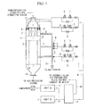
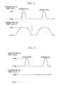
- FIG. 1 An embodiment of the present invention will be described below using the diagram of a backwashing-gas system in an apparatus for backwashing filter for a pressurized-fluidized-bed combustion boiler shown in Fig. 1 and the explanatory diagram for the sequence of associated operations between backwashing-gas front and rear valves shown in Fig. 2 .
- a total of four blocks are provided as filter blocks, two of which are in a honeycomb-type element (filter element) 2 at a top portion of a pressure vessel 1 and two of which are in a cylinder-type element (filter element) 3 at a bottom portion.
- a backwashing-gas system 4 is divided into four subsystems and, in each system, a number of backwashing nozzles 5 required for the corresponding block is provided, and a set of backwashing valves constituted of a backwashing-gas front valve (second backwashing valve) 6, a backwashing-gas rear valve (first backwashing valve) 7, and a manual bypass valve 8 is provided on the upstream side of the backwashing nozzle 5.
- a backwashing-gas buffer tank 9 is provided upstream of the backwashing-gas system 4, and, in addition, each pressurized-fluidized-bed-combustion boiler filter is connected to the backwashing-gas buffer tank 9 via a pipe 10.
- Two high-pressure gas compressors 11 are provided upstream of the backwashing-gas buffer tank 9 and, of these two compressors, one compressor is used as an auxiliary unit.
- the thus-configured backwashing-gas system 4 is operated as follows. That is, regarding high-temperature dust-containing gas that has entered from a dust-containing gas inlet 12 disposed at the top portion of the pressure vessel 1 of the pressurized-fluidized-bed-combustion boiler filter, one part thereof is subjected to dust removal in the two filter blocks at the top portion, which are configured of the porous-material honeycomb-type elements 2, and the remaining high-temperature dust-containing gas is subjected to dust removal in the two filter blocks formed of the cylinder-type elements 3 divided by a top-portion partitioning pipe plate (partitioning plate) 13, bottom-portion partitioning pipe plate (partitioning plate) 14, and inner-cylinder/outer-cylinder partitioning plate that are disposed at the bottom portion.
- Purified gas that has passed through individual elements is removed to the outside via corresponding purified-gas lead-out pipes 15 and, after being combined, moves toward a gas turbine disposed downstream thereof. Dust that has been removed by each filter block drops to a dust hopper disposed at the bottom portion on the high-temperature dust-containing gas side and is discharged from a dust hopper outlet 16.
- dust adhered to the high-temperature dust-containing gas side of each element does not necessarily drop off naturally, and it is necessary to cause a gas flow in a direction opposite to a normal flow, that is, to increase a gas pressure by applying a pressure wave of high-pressure gas in the opposite direction for an extremely short period of time (for example, 0.5 second) to shake off the dust adhered on the high-temperature dust-containing gas side, i.e., to perform backwashing.
- This backwashing is usually performed cyclically block by block in turn, and backwashing intervals are designed to be about several minutes.
- the backwashing-gas front valve 6 slowly moves from a fully-closed position to a fully-open position over a predetermined period of time (for example, 2 to 10 seconds). At this time, the backwashing-gas rear valve 7 does not move, remaining in the fully-closed position (maintains the fully-closed position).
- the backwashing-gas rear valve 7 quickly moves from the fully-closed position to the fully-open position over an extremely short period of time (for example, 0.1 to 1 second), and thus, the backwashing-gas front valve 6 and the backwashing-gas rear valve 7 are in the fully-open positions, and the backwashing is performed for an extremely short period of time (for example, 0.1 to 1 second).
- the backwashing-gas rear valve 7 quickly moves from the fully-open position to the fully-closed position over an extremely short period of time (for example, 0.1 to 1 second).
- the backwashing-gas front valve 6 does not move, remaining in the fully-open position (maintains the fully-open position).
- a predetermined period of time for example, 1 to 2 seconds
- the backwashing-gas front valve 6 slowly moves from the fully-open position to the fully-closed position over a predetermined period of time (for example, 2 to 10 seconds), and the backwashing-gas front valve 6 reaches the fully-closed position, thus ending the backwashing cycle.
- a predetermined period of time for example, 4 to 10 minutes
- the apparatus for backwashing filter it is possible to reduce deterioration of a rotation shaft, a bearing, a valve piece, etc., of the backwashing-gas front valve 6 as compared with a conventional apparatus; even when there is considerable deterioration in a rotation shaft, a bearing, a valve piece, etc., of the backwashing-gas rear valve 7, it is possible to completely block a channel to which the backwashing-gas front valve 6 and the backwashing-gas rear valve 7 are connected by having the backwashing-gas front valve 6 in the fully-closed position; and thus, it is possible to ensure the reliability of the backwashing valves constituted of the backwashing-gas front valves 6 and the backwashing-gas rear valves 7.
- FIG. 3 Another embodiment of the present invention will be described using the explanatory diagram for the sequence of associated operations between backwashing-gas front and rear valves shown in Fig. 3 .
- this embodiment differs from the above-described first embodiment in that the backwashing-gas front valve 6 is constantly maintained in the fully-open position (except for when it needs to be moved to the fully-closed position). That is, upon starting a backwashing cycle, the backwashing-gas rear valve 7 quickly moves from the fully-closed position to the fully-open position over an extremely short period of time (for example, 0.1 to 1 second), and the backwashing-gas rear valve 7 reaches the fully-closed position, thus performing backwashing for an extremely short period of time (for example, 0.1 to 1 second).
- an extremely short period of time for example, 0.1 to 1 second
- the backwashing-gas rear valve 7 quickly moves from the fully-open position to the fully-closed position over an extremely short period of time (for example, 0.1 to 1 second), thus ending the backwashing cycle. Then, when a predetermined period of time (for example, 4 to 10 minutes) has passed, the backwashing-gas rear valve 7 begins to move again from the fully-closed position to the fully-open position, thus starting the next backwashing cycle.
- a predetermined period of time for example, 4 to 10 minutes
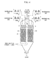
- the application of the apparatus for backwashing filter according to the present invention is not limited to integrated coal gasification combined cycle systems equipped with the pressure vessel 1 shown in Fig. 1 ; it is also applicable to integrated coal gasification combined cycle systems equipped with a pressure vessel 21 shown in Fig. 4 .
- reference signs 22, 23, and 24 in Fig. 4 denote a gas lead-out pipe, a cylinder-type element (candle-type filter element), and a top-portion partitioning plate (tube sheet), respectively.
Landscapes
- Chemical & Material Sciences (AREA)
- Engineering & Computer Science (AREA)
- Combustion & Propulsion (AREA)
- Chemical Kinetics & Catalysis (AREA)
- Oil, Petroleum & Natural Gas (AREA)
- Organic Chemistry (AREA)
- General Chemical & Material Sciences (AREA)
- Mechanical Engineering (AREA)
- General Engineering & Computer Science (AREA)
- Filtering Of Dispersed Particles In Gases (AREA)
Abstract
Description
- The present invention relates to an apparatus for backwashing filter (dust removal device) that mainly uses a filter element formed of a porous material to remove dust from gases containing dust.
- A known apparatus for backwashing filter is, for example, disclosed in
Patent Literature 1. -
- {PTL 1} The Publication of Japanese Patent No.
3197144 - However, with the apparatus for backwashing filter disclosed in the above-described
Patent Literature 1, a first backwashing valve (backwashing-gas front valve) and a second backwashing valve (backwashing-gas rear valve) are both configured so as to move quickly in an extremely short period of time (about 0.1 second) from a fully-closed position to a fully-open position, or from the fully-open position to the fully-closed position. Consequently, as the number of opening/closing operations increases, rotation shafts, bearings, valve bodies, etc., of the first backwashing valve and second backwashing valve become deteriorated, making it impossible to completely block channels connected to the first backwashing valve and second backwashing valve, resulting in the problem of difficulties in ensuring reliability of backwashing valves constituted of the first backwashing valve and the second backwashing valve. - The present invention has been made in view of the above-described circumstances, and an object thereof is to provide an apparatus for backwashing filter that is capable of ensuring the reliability of backwashing valves constituted of a first backwashing valves and a second backwashing valves.
- In order to solve the above-described problems, the present invention employs the following solutions.
An apparatus for backwashing filter according to a first aspect of the present invention is an apparatus for backwashing filter in a dust removal device using porous material, having a plurality of filter blocks which are constituted of a plurality of filter elements accommodated in a pressure vessel and partitioning plates that partition or support these filter blocks, the pressure vessel being internally divided into a space for dust-containing gas, which includes a dust hopper, and a plurality of spaces for purified gas; in an apparatus for backwashing filter that periodically performs backwashing of the filter elements for each of the filter blocks, wherein a backwashing nozzle directed toward the filter elements is provided inside purified-gas lead-out pipes or inside spaces upstream thereof, each of which is connected to the plurality of spaces for the purified gas or a filter-element outlet, a first backwashing valve that controls gas for backwashing and a second backwashing valve that operates at slower speed than the first backwashing valve are disposed, in two series, at backwashing-gas introducing pipes individually provided for each of the filter blocks. - With the apparatus for backwashing filter according to the above-described first aspect, upon starting a backwashing cycle, first, the second backwashing valve slowly moves from a fully-closed position to a fully-open position over a predetermined period of time. At this time, the first backwashing valve does not move, remaining in the fully-closed position (maintains the fully-closed position). When the second backwashing valve reaches the fully-open position and a predetermined period of time has passed, the first backwashing valve quickly moves from the fully-closed position to the fully-open position over an extremely short period of time, and thus, the second backwashing valve and the first backwashing valve are in the fully-open positions and the backwashing is performed for an extremely short period of time. When the backwashing is completed, the first backwashing valve quickly moves from the fully-open position to the fully-closed position over an extremely short period of time. At this time, the second backwashing valve does not move, remaining in the fully-open position (maintains the fully-open position). When the first backwashing valve reaches the fully-closed position and a predetermined period of time has passed, the second backwashing valve slowly moves from the fully-open position to the fully-closed position over a predetermined period of time, and the second backwashing valve reaches the fully-closed position, thus ending the backwashing cycle. Then, when a predetermined period of time has passed, the second backwashing valve begins to move again from the fully-closed position to the fully-opened position, thus starting the next backwashing cycle.
- Accordingly, it is possible to reduce deterioration of a rotation shaft, a bearing, a valve body, etc., of the second backwashing valve; even when there is considerable deterioration in a rotation shaft, a bearing, a valve body, etc., of the first backwashing valve, it is possible to completely block a channel to which the first backwashing valve and the second backwashing valve are connected by having the second backwashing valve in the fully-closed position; and thus, it is possible to ensure the reliability of a backwashing valve constituted of the first backwashing valve and the second backwashing valve.
- An apparatus for backwashing filter according to a second aspect of the present invention is an apparatus for backwashing filter in a dust removal device using porous material, having a plurality of filter blocks which are constituted of a plurality of filter elements accommodated in a pressure vessel and partitioning plates that partition or support these filter blocks, the pressure vessel being internally divided into a space for dust-containing gas, which includes a dust hopper, and a plurality of spaces for purified gas; in an apparatus for backwashing filter that periodically performs backwashing of the filter elements for each of the filter blocks, wherein a backwashing nozzle directed toward the filter elements is provided inside purified-gas lead-out pipes or inside spaces upstream thereof, each of which is connected to the plurality of spaces for the purified gas or a filter-element outlet, a first backwashing valve and a second backwashing valve are disposed, in two series, at backwashing-gas introducing pipes individually provided for each of the filter blocks, and gas for backwashing is controlled by the first backwashing valve alone.
- With the apparatus for backwashing filter according to the above-described second aspect, upon starting a backwashing cycle, the second backwashing valve quickly moves from the fully-closed position to the fully-open position over an extremely short period of time, and the second backwashing valve reaches the fully-open position, thus performing the backwashing for an extremely short period of time. When the backwashing is completed, the second backwashing valve quickly moves from the fully-open position to the fully-closed position over the extremely short period of time, thus ending the backwashing cycle. Then, when a predetermined period of time has passed, the second backwashing valve begins to move again from the fully-closed position to the fully-open position, thus starting the next backwashing cycle.
Note that, during a backwashing cycle and between one backwashing cycle and another backwashing cycle, the first backwashing valve does not move, remaining in the fully-closed position (maintains the fully-closed position). - Accordingly, it is possible to reduce deterioration of the rotation shaft, the bearing, the valve piece, etc., of the second backwashing valve; even when there is considerable deterioration in the rotation shaft, the bearing, the valve piece, etc., of the first backwashing valve, it is possible to completely block the channel to which the first backwashing valve and the second backwashing valve are connected, by having the second backwashing valve in the fully-closed position; and thus it is possible to ensure the reliability of a backwashing valves constituted of the first backwashing valve and the second backwashing valve.
- An integrated coal gasification combined cycle (IGCC) system according to a third aspect of the present invention is equipped with an apparatus for backwashing filter that is capable of reducing the deterioration of the rotation shaft, the bearing, the valve piece, etc., of the second backwashing valve; that is capable of, even when there is considerable deterioration in the rotation shaft, the bearing, the valve piece, etc., of the first backwashing valve, completely blocking the channel to which the first backwashing valve and the second backwashing valve are connected by having the second backwashing valve in the fully-closed position; and that is capable of ensuring the reliability of a backwashing valve constituted of the first backwashing valve and the second backwashing valve.
- With the integrated coal gasification combined cycle system according to the above-described third aspect, it is possible to ensure the reliability of a backwashing valve constituted of the first backwashing valve and the second backwashing valve, and thus, it is possible to improve the reliability of the system as a whole.
- The present invention affords an advantage in that it is possible to ensure the reliability of a backwashing valve constituted of a first backwashing valve and a second backwashing valve.
-
- {
Fig. 1} Fig. 1 is a diagram of a gas system in an apparatus for backwashing filter for pressurized-fluidized-bed combustion boilers according to the present invention. - {
Fig. 2} Fig. 2 is an explanatory diagram for a sequence of associated operations between backwashing-gas front and rear valves according to an embodiment of the present invention. - {
Fig. 3} Fig. 3 is an explanatory diagram for a sequence of associated operations between backwashing-gas front and rear valves according to another embodiment of the present invention. - {
Fig. 4} Fig. 4 is a diagram showing another embodiment of the present invention and is a diagram showing a gas system around a pressure vessel. - An embodiment of the present invention will be described below using the diagram of a backwashing-gas system in an apparatus for backwashing filter for a pressurized-fluidized-bed combustion boiler shown in
Fig. 1 and the explanatory diagram for the sequence of associated operations between backwashing-gas front and rear valves shown inFig. 2 .
In this embodiment, a total of four blocks are provided as filter blocks, two of which are in a honeycomb-type element (filter element) 2 at a top portion of apressure vessel 1 and two of which are in a cylinder-type element (filter element) 3 at a bottom portion. Consequently, a backwashing-gas system 4 is divided into four subsystems and, in each system, a number ofbackwashing nozzles 5 required for the corresponding block is provided, and a set of backwashing valves constituted of a backwashing-gas front valve (second backwashing valve) 6, a backwashing-gas rear valve (first backwashing valve) 7, and amanual bypass valve 8 is provided on the upstream side of thebackwashing nozzle 5. - A backwashing-
gas buffer tank 9 is provided upstream of the backwashing-gas system 4, and, in addition, each pressurized-fluidized-bed-combustion boiler filter is connected to the backwashing-gas buffer tank 9 via apipe 10.
Two high-pressure gas compressors 11 are provided upstream of the backwashing-gas buffer tank 9 and, of these two compressors, one compressor is used as an auxiliary unit. - The thus-configured backwashing-
gas system 4 is operated as follows. That is, regarding high-temperature dust-containing gas that has entered from a dust-containinggas inlet 12 disposed at the top portion of thepressure vessel 1 of the pressurized-fluidized-bed-combustion boiler filter, one part thereof is subjected to dust removal in the two filter blocks at the top portion, which are configured of the porous-material honeycomb-type elements 2, and the remaining high-temperature dust-containing gas is subjected to dust removal in the two filter blocks formed of the cylinder-type elements 3 divided by a top-portion partitioning pipe plate (partitioning plate) 13, bottom-portion partitioning pipe plate (partitioning plate) 14, and inner-cylinder/outer-cylinder partitioning plate that are disposed at the bottom portion. - Purified gas that has passed through individual elements is removed to the outside via corresponding purified-gas lead-out
pipes 15 and, after being combined, moves toward a gas turbine disposed downstream thereof. Dust that has been removed by each filter block drops to a dust hopper disposed at the bottom portion on the high-temperature dust-containing gas side and is discharged from adust hopper outlet 16. - However, dust adhered to the high-temperature dust-containing gas side of each element does not necessarily drop off naturally, and it is necessary to cause a gas flow in a direction opposite to a normal flow, that is, to increase a gas pressure by applying a pressure wave of high-pressure gas in the opposite direction for an extremely short period of time (for example, 0.5 second) to shake off the dust adhered on the high-temperature dust-containing gas side, i.e., to perform backwashing. This backwashing is usually performed cyclically block by block in turn, and backwashing intervals are designed to be about several minutes.
- As shown in
Fig. 2 , upon starting a backwashing cycle, first, the backwashing-gas front valve 6 slowly moves from a fully-closed position to a fully-open position over a predetermined period of time (for example, 2 to 10 seconds). At this time, the backwashing-gasrear valve 7 does not move, remaining in the fully-closed position (maintains the fully-closed position). When the backwashing-gas front valve 6 reaches the fully-open position and a predetermined period of time (for example, 1 to 2 seconds) has passed, the backwashing-gasrear valve 7 quickly moves from the fully-closed position to the fully-open position over an extremely short period of time (for example, 0.1 to 1 second), and thus, the backwashing-gas front valve 6 and the backwashing-gasrear valve 7 are in the fully-open positions, and the backwashing is performed for an extremely short period of time (for example, 0.1 to 1 second). When the backwashing is completed, the backwashing-gasrear valve 7 quickly moves from the fully-open position to the fully-closed position over an extremely short period of time (for example, 0.1 to 1 second). At this time, the backwashing-gas front valve 6 does not move, remaining in the fully-open position (maintains the fully-open position). When the backwashing-gasrear valve 7 reaches the fully-closed position and a predetermined period of time (for example, 1 to 2 seconds) has passed, the backwashing-gas front valve 6 slowly moves from the fully-open position to the fully-closed position over a predetermined period of time (for example, 2 to 10 seconds), and the backwashing-gas front valve 6 reaches the fully-closed position, thus ending the backwashing cycle. Then, when a predetermined period of time (for example, 4 to 10 minutes) has passed, the backwashing-gas front valve 6 begins to move again from the fully-closed position to the fully-open position, thus starting the next backwashing cycle. - With the apparatus for backwashing filter according to this embodiment, it is possible to reduce deterioration of a rotation shaft, a bearing, a valve piece, etc., of the backwashing-
gas front valve 6 as compared with a conventional apparatus; even when there is considerable deterioration in a rotation shaft, a bearing, a valve piece, etc., of the backwashing-gasrear valve 7, it is possible to completely block a channel to which the backwashing-gas front valve 6 and the backwashing-gasrear valve 7 are connected by having the backwashing-gas front valve 6 in the fully-closed position; and thus, it is possible to ensure the reliability of the backwashing valves constituted of the backwashing-gas front valves 6 and the backwashing-gasrear valves 7. - Another embodiment of the present invention will be described using the explanatory diagram for the sequence of associated operations between backwashing-gas front and rear valves shown in
Fig. 3 .
As shown inFig. 3 , this embodiment differs from the above-described first embodiment in that the backwashing-gas front valve 6 is constantly maintained in the fully-open position (except for when it needs to be moved to the fully-closed position).
That is, upon starting a backwashing cycle, the backwashing-gasrear valve 7 quickly moves from the fully-closed position to the fully-open position over an extremely short period of time (for example, 0.1 to 1 second), and the backwashing-gasrear valve 7 reaches the fully-closed position, thus performing backwashing for an extremely short period of time (for example, 0.1 to 1 second). When the backwashing is completed, the backwashing-gasrear valve 7 quickly moves from the fully-open position to the fully-closed position over an extremely short period of time (for example, 0.1 to 1 second), thus ending the backwashing cycle. Then, when a predetermined period of time (for example, 4 to 10 minutes) has passed, the backwashing-gasrear valve 7 begins to move again from the fully-closed position to the fully-open position, thus starting the next backwashing cycle. - With the apparatus for backwashing filter according to this embodiment, it is possible to reduce deterioration of the rotation shaft, the bearing, the valve piece, etc., of the backwashing-
gas front valve 6 as compared with the first embodiment; even when there is considerable deterioration in the rotation shaft, the bearing, the valve piece, etc., of the backwashing-gasrear valve 7, it is possible to completely block the channel to which the backwashing-gas front valve 6 and the backwashing-gasrear valve 7 are connected, by having the backwashing-gas front valve 6 in the fully-closed position; and thus it is possible to ensure the reliability of the backwashing valves constituted of the backwashing-gas front valves 6 and the backwashing-gasrear valves 7. - Note that the present invention is not limited to the above-described embodiments, and various alterations and modifications are possible, for example, to the number and operation sequence of the backwashing valves, within a range that does not depart from the gist of the present invention.
- The application of the apparatus for backwashing filter according to the present invention is not limited to integrated coal gasification combined cycle systems equipped with the
pressure vessel 1 shown inFig. 1 ; it is also applicable to integrated coal gasification combined cycle systems equipped with apressure vessel 21 shown inFig. 4 .
Note that,reference signs 22, 23, and 24 inFig. 4 denote a gas lead-out pipe, a cylinder-type element (candle-type filter element), and a top-portion partitioning plate (tube sheet), respectively. -
- 1:
- pressure vessel
- 2:
- honeycomb-type element (filter element)
- 3:
- cylinder-type element (filter element)
- 4:
- backwashing-gas system
- 5:
- backwashing nozzle
- 6:
- backwashing-gas front valve (second backwashing valve)
- 7:
- backwashing-gas rear valve (first backwashing valve)
- 13:
- top-portion partitioning pipe plate (partitioning plate)
- 14:
- bottom-portion partitioning pipe plate (partitioning plate)
- 15:
- purified-gas lead-out pipe
- 21:
- pressure vessel
- 23:
- cylinder-type element (candle-type filter element)
- 24:
- top-portion partitioning plate (tube sheet)
Claims (3)
- An apparatus for backwashing filter in a dust removal device using porous material, having a plurality of filter blocks which are constituted of a plurality of filter elements accommodated in a pressure vessel and partitioning plates that partition or support these filter blocks, the pressure vessel being internally divided into a space for dust-containing gas, which includes a dust hopper, and a plurality of spaces for purified gas;
in an apparatus for backwashing filter that periodically performs backwashing of the filter elements for each of the filter blocks, wherein a backwashing nozzle directed toward the filter elements is provided inside purified-gas lead-out pipes or inside spaces upstream thereof, each of which is connected to the plurality of spaces for the purified gas or a filter-element outlet,
a first backwashing valve that controls gas for backwashing and a second backwashing valve that operates at slower speed than the first backwashing valve are disposed, in a series including two or more thereof, at backwashing-gas introducing pipes individually provided for each of the filter blocks. - An apparatus for backwashing filter in a dust removal device using porous material, having a plurality of filter blocks which are constituted of a plurality of filter elements accommodated in a pressure vessel and partitioning plates that partition or support these filter blocks, the pressure vessel being internally divided into a space for dust-containing gas, which includes a dust hopper, and a plurality of spaces for purified gas;
in an apparatus for backwashing filter that periodically performs backwashing of the filter elements for each of the filter blocks, wherein a backwashing nozzle directed toward the filter elements is provided inside purified-gas lead-out pipes or inside spaces upstream thereof, each of which is connected to the plurality of spaces for the purified gas or a filter-element outlet,
a first backwashing valve and a second backwashing valve are disposed, in a series including two or more thereof, at backwashing-gas introducing pipes individually provided for each of the filter blocks, and gas for backwashing is controlled by the first backwashing valve alone. - An integrated coal gasification combined cycle system equipped with the apparatus for backwashing filter according to Claim 1 or 2.
Applications Claiming Priority (2)
| Application Number | Priority Date | Filing Date | Title |
|---|---|---|---|
| JP2008325234A JP5427402B2 (en) | 2008-12-22 | 2008-12-22 | Filter backwash equipment |
| PCT/JP2009/065666 WO2010073779A1 (en) | 2008-12-22 | 2009-09-08 | Back washing device of filter |
Publications (2)
| Publication Number | Publication Date |
|---|---|
| EP2386343A1 true EP2386343A1 (en) | 2011-11-16 |
| EP2386343A4 EP2386343A4 (en) | 2012-10-10 |
Family
ID=42287406
Family Applications (1)
| Application Number | Title | Priority Date | Filing Date |
|---|---|---|---|
| EP09834585A Withdrawn EP2386343A4 (en) | 2008-12-22 | 2009-09-08 | Back washing device of filter |
Country Status (9)
| Country | Link |
|---|---|
| US (2) | US20110154788A1 (en) |
| EP (1) | EP2386343A4 (en) |
| JP (1) | JP5427402B2 (en) |
| KR (1) | KR101247882B1 (en) |
| CN (1) | CN102099092B (en) |
| AU (1) | AU2009332116A1 (en) |
| CA (1) | CA2729941C (en) |
| WO (1) | WO2010073779A1 (en) |
| ZA (1) | ZA201100276B (en) |
Families Citing this family (7)
| Publication number | Priority date | Publication date | Assignee | Title |
|---|---|---|---|---|
| JP5427402B2 (en) | 2008-12-22 | 2014-02-26 | 三菱重工業株式会社 | Filter backwash equipment |
| JP5787742B2 (en) * | 2011-12-20 | 2015-09-30 | 三菱日立パワーシステムズ株式会社 | Filter element playback method |
| CN103611343B (en) * | 2013-12-10 | 2015-07-22 | 武汉市汉江石油物资技术开发有限责任公司 | Backwash spray nozzle for granular filter material filter device |
| US10272382B2 (en) * | 2016-05-31 | 2019-04-30 | United Technologies Corporation | Carrier gas reclamation system and method |
| DE102019127751A1 (en) * | 2019-10-15 | 2021-04-15 | Herding Gmbh Filtertechnik | Filter device and method for cleaning a filter element of a filter device |
| GB2592267A (en) * | 2020-02-24 | 2021-08-25 | Altair Uk Ltd | Pulse nozzle for filter cleaning systems |
| CN116179244B (en) * | 2023-04-04 | 2023-09-05 | 太原理工大学 | A pressurized gasifier for coal chemical industry |
Family Cites Families (36)
| Publication number | Priority date | Publication date | Assignee | Title |
|---|---|---|---|---|
| JPS497542B1 (en) * | 1970-12-28 | 1974-02-21 | ||
| GB2016432B (en) | 1978-03-17 | 1982-11-24 | Hoelter H | Metal oxide-coated coated silica fibres hot gas filter |
| US4295686A (en) * | 1978-11-27 | 1981-10-20 | Pemco-Kalamazoo, Inc. | Disk wheel with resilient bearing support and rigid annular tread mounting surface |
| DE2906353C3 (en) * | 1979-02-19 | 1983-02-03 | Gebrüder Bühler AG, 9240 Uzwil | Process and filter control system for cyclical counter-flushing of membrane valve-operated filter bags |
| US4343631A (en) * | 1981-01-30 | 1982-08-10 | Westinghouse Electric Corp. | Hot gas particulate removal |
| US4690700A (en) * | 1983-11-07 | 1987-09-01 | Howeth David Franklin | Backflushed air filters with quick opening multiple discharge valve |
| DE3412930A1 (en) * | 1984-04-06 | 1985-10-17 | L. & C. Steinmüller GmbH, 5270 Gummersbach | METHOD AND DEVICE FOR EJECTING SOLIDS (DUST) FROM PROCESS GASS UNDER PRESSURE |
| US4539025A (en) * | 1984-09-26 | 1985-09-03 | Westinghouse Electric Corp. | Filtering system |
| JPH01189318A (en) | 1988-01-26 | 1989-07-28 | Mitsubishi Heavy Ind Ltd | Dust collector |
| JPH04118016A (en) * | 1990-09-07 | 1992-04-20 | Mitsui Eng & Shipbuild Co Ltd | Method for dust collection by bag filter |
| JP3128261B2 (en) * | 1991-04-24 | 2001-01-29 | 旭硝子株式会社 | Backwashing device for hot gas duster and method for backwashing hot gas duster |
| US5116395A (en) * | 1991-07-09 | 1992-05-26 | Pneumafil Corporation | Dust collection with programmable cleaning air control |
| US5167676A (en) * | 1992-04-08 | 1992-12-01 | The United States Of America As Represented By The United States Department Of Energy | Apparatus and method for removing particulate deposits from high temperature filters |
| US5254144A (en) * | 1992-08-19 | 1993-10-19 | Pyropower Corporation | Method and appartus for separating particulate material from combustible gases |
| JP3197144B2 (en) * | 1994-03-24 | 2001-08-13 | 三菱重工業株式会社 | Backwashing equipment for ceramic filters |
| JPH08192019A (en) | 1995-01-13 | 1996-07-30 | Japan Pionics Co Ltd | Filtration device with backwash mechanism |
| JPH09234324A (en) * | 1996-03-01 | 1997-09-09 | Mitsubishi Heavy Ind Ltd | Dust removing apparatus |
| JPH1028827A (en) * | 1996-07-19 | 1998-02-03 | Mitsubishi Heavy Ind Ltd | Dust collector |
| JP3765624B2 (en) * | 1996-07-22 | 2006-04-12 | 株式会社ナムコ | Running game device |
| JP3572148B2 (en) * | 1996-07-22 | 2004-09-29 | 三菱重工業株式会社 | Dust removal device |
| JPH10197022A (en) * | 1997-01-09 | 1998-07-31 | Kazutoshi Zeida | Range hood filter |
| US6056796A (en) * | 1998-02-09 | 2000-05-02 | The United States Of America As Represented By The United States Department Of Energy | Rigid porous filter |
| JP3416511B2 (en) * | 1998-03-13 | 2003-06-16 | 三菱重工業株式会社 | Dust removal device |
| DE19917165C2 (en) * | 1999-04-16 | 2001-02-08 | Karlsruhe Forschzent | Process for cleaning tubular filter elements and device for carrying out the process |
| KR20000020312U (en) * | 1999-05-03 | 2000-12-05 | 민흥기 | Apparatus to inject compressed air of dust collector |
| DE60014627T2 (en) * | 1999-05-21 | 2005-11-17 | Shell Internationale Research Maatschappij B.V. | DEVICE AND METHOD FOR REMOVING SOLID PARTICLES FROM GASES |
| JP2001000813A (en) * | 1999-06-18 | 2001-01-09 | Babcock Hitachi Kk | Filter |
| JP2001017813A (en) * | 1999-07-05 | 2001-01-23 | Nkk Corp | How to operate the bag filter |
| US6273925B1 (en) * | 1999-09-10 | 2001-08-14 | Mary Anne Alvin | Filter assembly for metallic and intermetallic tube filters |
| JP3649176B2 (en) * | 2001-10-31 | 2005-05-18 | 三菱マテリアル株式会社 | Solid content removal equipment in high pressure process |
| JP4057281B2 (en) | 2001-11-07 | 2008-03-05 | 住友ゴム工業株式会社 | Pneumatic tire |
| JP2004066187A (en) * | 2002-08-09 | 2004-03-04 | Jutaku Service:Kk | Non-woven fabric filter for kitchen ventilation air-guide-port and holding member therefor |
| JP2004196894A (en) * | 2002-12-17 | 2004-07-15 | Mitsubishi Heavy Ind Ltd | Dust collector |
| FR2851290B1 (en) * | 2003-02-18 | 2007-02-09 | Peugeot Citroen Automobiles Sa | ELECTROMECHANICAL VALVE CONTROL ACTUATOR FOR INTERNAL COMBUSTION ENGINE |
| US7833329B2 (en) * | 2007-05-03 | 2010-11-16 | Mott Corporation | Plenum based high pressure blowback gas delivery system in a continuous process flow filtration system |
| JP5427402B2 (en) | 2008-12-22 | 2014-02-26 | 三菱重工業株式会社 | Filter backwash equipment |
-
2008
- 2008-12-22 JP JP2008325234A patent/JP5427402B2/en active Active
-
2009
- 2009-09-08 US US13/003,722 patent/US20110154788A1/en not_active Abandoned
- 2009-09-08 KR KR1020117001415A patent/KR101247882B1/en not_active Expired - Fee Related
- 2009-09-08 CA CA2729941A patent/CA2729941C/en active Active
- 2009-09-08 AU AU2009332116A patent/AU2009332116A1/en not_active Abandoned
- 2009-09-08 WO PCT/JP2009/065666 patent/WO2010073779A1/en not_active Ceased
- 2009-09-08 EP EP09834585A patent/EP2386343A4/en not_active Withdrawn
- 2009-09-08 CN CN200980128552.8A patent/CN102099092B/en not_active Expired - Fee Related
-
2011
- 2011-01-11 ZA ZA2011/00276A patent/ZA201100276B/en unknown
-
2013
- 2013-11-06 US US14/073,529 patent/US9731240B2/en active Active
Also Published As
| Publication number | Publication date |
|---|---|
| KR20110036584A (en) | 2011-04-07 |
| AU2009332116A1 (en) | 2010-07-01 |
| JP2010142774A (en) | 2010-07-01 |
| WO2010073779A1 (en) | 2010-07-01 |
| US20140059982A1 (en) | 2014-03-06 |
| KR101247882B1 (en) | 2013-03-26 |
| US20110154788A1 (en) | 2011-06-30 |
| CN102099092B (en) | 2014-09-17 |
| CA2729941C (en) | 2013-05-21 |
| EP2386343A4 (en) | 2012-10-10 |
| JP5427402B2 (en) | 2014-02-26 |
| ZA201100276B (en) | 2011-10-26 |
| CA2729941A1 (en) | 2010-07-01 |
| CN102099092A (en) | 2011-06-15 |
| US9731240B2 (en) | 2017-08-15 |
Similar Documents
| Publication | Publication Date | Title |
|---|---|---|
| US9731240B2 (en) | Method for backwashing filter | |
| JP5220190B2 (en) | Method for cleaning a fuel system of a gas turbine and the fuel system | |
| US8673066B2 (en) | Dust-removing method | |
| EP3467381B1 (en) | Exhaust gas denitration device, incinerator and exhaust gas denitration method | |
| CN100475310C (en) | Purification process and device for filter material of gas filter | |
| WO2013080525A1 (en) | Injector control method | |
| CN101328895B (en) | Water-cooled air compressor | |
| CN105727648B (en) | Pulse backblowing deashing device and its gas ejector, filter device | |
| US5518513A (en) | Dust removing apparatus | |
| JP5665928B2 (en) | Filter backwash equipment | |
| CN210645755U (en) | Quick row of active burnt material structure and active burnt discharge system | |
| KR20110029393A (en) | Dust Collector of Dust Collecting System with Ceramic Candle Filter and Its Method | |
| US9840966B2 (en) | Auxiliaryy fluid flow system debris filter | |
| JP3197144B2 (en) | Backwashing equipment for ceramic filters | |
| CN115615705B (en) | A fuel shortage test apparatus and test method for a turbine engine fuel system | |
| CN210814660U (en) | Tail gas treatment equipment for coking device | |
| KR200448937Y1 (en) | Turbine-side supercharger cleaning device of diesel engine | |
| JP3110166B2 (en) | Dust remover backwashing device | |
| JP3293953B2 (en) | Dust remover | |
| JP2010236366A (en) | Exhaust gas treatment system for engine equipped with black smoke removing device and method for cleaning black smoke removing device | |
| CN115253403A (en) | A kind of double filter material filter operation control method and module | |
| JP2008132424A (en) | Exhaust gas treatment apparatus and operation method of waste treatment facility equipped with the same | |
| KR20140041077A (en) | Lube oil purifying system for engine | |
| JPH06339609A (en) | Deduster | |
| JPH08219412A (en) | Cyclone ash discharge device in a pressurized fluidized bed combustion plant |
Legal Events
| Date | Code | Title | Description |
|---|---|---|---|
| PUAI | Public reference made under article 153(3) epc to a published international application that has entered the european phase |
Free format text: ORIGINAL CODE: 0009012 |
|
| 17P | Request for examination filed |
Effective date: 20110113 |
|
| AK | Designated contracting states |
Kind code of ref document: A1 Designated state(s): AT BE BG CH CY CZ DE DK EE ES FI FR GB GR HR HU IE IS IT LI LT LU LV MC MK MT NL NO PL PT RO SE SI SK SM TR |
|
| DAX | Request for extension of the european patent (deleted) | ||
| A4 | Supplementary search report drawn up and despatched |
Effective date: 20120906 |
|
| RIC1 | Information provided on ipc code assigned before grant |
Ipc: B01D 46/00 20060101ALI20120831BHEP Ipc: B01D 46/24 20060101ALI20120831BHEP Ipc: C10J 3/54 20060101ALI20120831BHEP Ipc: B01D 46/42 20060101AFI20120831BHEP Ipc: C10K 1/02 20060101ALI20120831BHEP Ipc: F02C 3/28 20060101ALI20120831BHEP |
|
| STAA | Information on the status of an ep patent application or granted ep patent |
Free format text: STATUS: THE APPLICATION HAS BEEN WITHDRAWN |
|
| 18W | Application withdrawn |
Effective date: 20140620 |