EP2385710A2 - Fault diagnostics arrangement for electric drive system, and electric drive system - Google Patents
Fault diagnostics arrangement for electric drive system, and electric drive system Download PDFInfo
- Publication number
- EP2385710A2 EP2385710A2 EP11164880A EP11164880A EP2385710A2 EP 2385710 A2 EP2385710 A2 EP 2385710A2 EP 11164880 A EP11164880 A EP 11164880A EP 11164880 A EP11164880 A EP 11164880A EP 2385710 A2 EP2385710 A2 EP 2385710A2
- Authority
- EP
- European Patent Office
- Prior art keywords
- electric drive
- fault
- subsystems
- fault diagnostics
- drive system
- Prior art date
- Legal status (The legal status is an assumption and is not a legal conclusion. Google has not performed a legal analysis and makes no representation as to the accuracy of the status listed.)
- Withdrawn
Links
Images




Classifications
-
- G—PHYSICS
- G05—CONTROLLING; REGULATING
- G05B—CONTROL OR REGULATING SYSTEMS IN GENERAL; FUNCTIONAL ELEMENTS OF SUCH SYSTEMS; MONITORING OR TESTING ARRANGEMENTS FOR SUCH SYSTEMS OR ELEMENTS
- G05B23/00—Testing or monitoring of control systems or parts thereof
- G05B23/02—Electric testing or monitoring
- G05B23/0205—Electric testing or monitoring by means of a monitoring system capable of detecting and responding to faults
-
- H—ELECTRICITY
- H04—ELECTRIC COMMUNICATION TECHNIQUE
- H04Q—SELECTING
- H04Q9/00—Arrangements in telecontrol or telemetry systems for selectively calling a substation from a main station, in which substation desired apparatus is selected for applying a control signal thereto or for obtaining measured values therefrom
-
- G—PHYSICS
- G05—CONTROLLING; REGULATING
- G05B—CONTROL OR REGULATING SYSTEMS IN GENERAL; FUNCTIONAL ELEMENTS OF SUCH SYSTEMS; MONITORING OR TESTING ARRANGEMENTS FOR SUCH SYSTEMS OR ELEMENTS
- G05B19/00—Program-control systems
- G05B19/02—Program-control systems electric
- G05B19/04—Program control other than numerical control, i.e. in sequence controllers or logic controllers
- G05B19/048—Monitoring; Safety
-
- H—ELECTRICITY
- H04—ELECTRIC COMMUNICATION TECHNIQUE
- H04Q—SELECTING
- H04Q2209/00—Arrangements in telecontrol or telemetry systems
- H04Q2209/30—Arrangements in telecontrol or telemetry systems using a wired architecture
Definitions
- the invention relates to industrial electric drives, such as electric drives for turbines of wind power industry or electric drives for solar power industry, and particularly to fault diagnostics for electric drive systems.
- Electric drives are used for various applications, such as transport vehicle engines, different process and manufacturing technological devices and in energy industry.
- transport devices electric drives may be used in underground railway service or shipping service, for example.
- process and manufacturing technology electric drives may be used e.g. in conveyors, mixers or in paper machines, for instance.
- energy industry electric drives may be used in turbines of wind power industry or in solar power industry, for example.
- the most common types of electric drives are direct current drives and alternating current drives.
- direct current applications the current flowing through the field winding of the motor stator generates a magnetic field that is oriented perpendicular to the field generated by the armature coil. This provides a direct current motor with a torque that is easy to adjust in direct current use by changing the armature current and by maintaining a constant exciting current.
- the armature current also allows the rate of the direct current motor to be adjusted directly.
- Electric drives based on alternating current may be further divided into frequency-controlled alternating current drives, flux-vector-controlled alternating current drives and to alternating current drives using direct torque control (DTC).
- DTC direct torque control
- the alternating current drives based on flux vector control and DTC alternating current drives allow the torque of a three-phase motor to be adjusted, whereas in a frequency-controlled alternating current drive the load on the three-phase motor determines the torque.
- FIG. 1 shows the structure of a prior art electric drive.
- the prior art electric drive comprises a power supply 1, a frequency converter 2 and a load 3.
- the load 3 may be a motor 3, for example.
- the frequency converter 2 typically consists of a rectifier unit 4, a direct voltage intermediate circuit 5 and an inverter unit 6.
- the rectifier unit 4 of the frequency converter 2 converts alternating voltage coming from power supply 1 to direct voltage.
- the frequency converter 2 may be rectified by a 6-pulse diode bridge, for example.
- the direct voltage obtained from the rectifier unit 4 of the frequency converter 2 is stored to a direct voltage intermediate circuit 5 serving as an energy storage.
- the direct voltage intermediate circuit 5 of the frequency converter 2 may be implemented by means of storage capacitors.
- the inverter unit 6 of the frequency converter 2 From the direct current of the direct voltage intermediate circuit 5 the inverter unit 6 of the frequency converter 2 produces alternating current a desired frequency needed by the motor 3 representing the load.
- the inverter unit 6 of the frequency converter 2 may be implemented by means of IGBTs (IGBT, Insulated-gate Bipolar Transistor), for example.
- FIG. 2 shows the structure of an alternative prior art electric drive.
- the alternative prior art electric drive comprises a power supply 7 and a load consisting of a number of motors 8, 9, 10.
- the alternative electric drive comprises a rectifier unit 11, a direct voltage intermediate circuit 12 and a number of separate inverter units 13, 14, 15.
- the rectifier unit 11 of the electric drive converts alternating current coming from the power supply 7 to direct voltage, which is stored into the direct voltage intermediate circuit 12 serving as an energy storage. From the direct current of the direct voltage intermediate circuit 12 the separate inverter units 13, 14, 15 of the electric drive produce alternating current of a desired frequency for their respective motors 13, 14, 15 representing the load.
- Electric drives are generally used at relative demanding circumstances and often also for critical applications. In fact, one of the main requirements imposed on an electric drive is its operational reliability. If an electric drive is damaged in an uncontrollable manner, in the worst case also the motor representing the load and the machine itself may become damaged and cause a great cumulative damage.
- each device or subsystem has a separate control board to control the operation of the device or subsystem in a fault situation.
- the control board shuts the subsystem down and, when less critical faults are concerned, the control board performs a corrective action by changing the control. All faults appearing in the device or the subsystem are recorded into a fault logger of the control board.
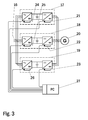
- FIG. 3 shows a fault diagnostics arrangement for a prior art electric drive.
- the prior art electric drive comprises three frequency converter units 17, 18, 19 and a generator 20.
- the frequency converter units 17, 18, 19 convert the electricity produced by the generator 20 to correspond to the frequency of the mains and supply the electricity thus generated to a network 16.
- Each of the frequency converter units 17, 18, 19 of the prior art electric drive comprises a rectifier unit, a direct voltage intermediate circuit and an inverter unit.
- Each inverter unit comprises a separate control board 21, 22, 23 and an inverter-unit-specific fault logger residing on the control board 21, 22, 23.
- the fault logger on the control board 21, 22, 23 documents all faults, warning and other events in accordance with the prior art. Event history stored in the fault logger of the control board 21, 22, 23 of the inverter unit in the frequency converter can be read by and also copied into a computer afterwards.
- each rectifier unit comprises a separate control board 24, 25, 26 and a rectifier-unit-specific fault logger residing on the control board 24, 25, 26.
- the fault logger on the control board 24, 25, 26 of the rectifier unit documents all faults, warnings and other events in accordance with the prior art.
- event history stored in the fault logger of the control board 24, 25, 26 of the rectifier unit in the frequency converter can be read by and also copied into a computer afterwards.
- Figure shows a computer which in a fault diagnostics situation, for example, may be connected over separate connections to read the fault logger data of the control boards 21, 22, 23 of the inverter unit and also those of the control boards 24, 25, 26 of the rectifier unit.
- the electric drive may comprise a number of other subsystems, such as a brake chopper subsystem and/or a liquid cooling plant subsystem.
- the electric drive may comprise diverse other subsystems, some of which are not involved in the motor control. Each subsystem thus typically also has a separate subsystem-specific control board and a separate fault logger data file of the control board.
- the prior a fault diagnostics arrangement for an electric drive has some major shortcomings. In a fault examination situation, numerous connections are laborious and complicated. Moreover, the prior art fault diagnostics arrangement does not give a reliable picture of the fault situation on the main system level of the electric drive. It has been noticed that in a fault examination situation the fault logger data of the subsystem-specific control boards 21 to 26 are difficult to analyse and place in a chronological order. In a prior art electric drive system it is difficult to conclude how the fault has emerged and advanced and also which part of the electric drive has been damaged and which not.
- An object of the invention is to provide a novel fault diagnostics arrangement for an electric drive system and an electric drive system for different industrial applications.
- the fault diagnostics arrangement of the invention for an electric drive system is characterized in that the electric drive system consists of a plural number of electric drive subsystems and the fault diagnostics arrangement of the electric drive system comprises subsystem control boards, to which event data of the subsystems is stored, one of the control boards of the electric drive system serving as a main control board of the electric drive system and the event data of the subsystems are transferred to the main control board from the control boards of the subsystems by a data transfer medium.
- the electric drive system of the invention is characterized in that the electric drive system consists of a plural number of electric drive subsystems and the fault diagnostics arrangement of the electric drive system comprises subsystem control boards, to which event data of the subsystems is stored, one of the control boards of the electric drive system serving as a main control board of the electric drive system and the event data of the subsystems are transferred to the main control board from the control boards of the subsystems by a data transfer medium.
- the present invention enables to achieve a number of advantages, as will become clear from the detailed disclosure.
- the fault diagnostics arrangement of the invention for an electric drive allows an extremely good and reliable picture of a fault situation to be obtained on the main system level of the electric drive.
- the fault diagnostics arrangement of the invention for an electric drive system enables to facilitate the analysis of the fault logger data in a fault examination situation, for example.
- FIG. 4 shows a fault diagnostics arrangement for an electric drive of an embodiment of the invention.
- the electric drive of the invention comprises a power supply 28, a frequency converter 29 and a load 30.
- the load 30 may be a motor 30, for example.
- the frequency converter 29 consists of a rectifier unit 31, a direct voltage intermediate circuit 32 and an inverter unit 33.
- the rectifier unit 31 of the frequency converter 29 of the electric drive of the invention converts alternating voltage coming from the power supply 28 to direct voltage.
- the frequency converter 29 may be rectified by a 6-pulse diode bridge, for example.
- the direct voltage obtained from the rectifier unit 31 of the frequency converter 29 is stored to a direct voltage intermediate circuit 32 serving as an energy storage.
- the direct voltage intermediate circuit 32 of the frequency converter 29 may be implemented by means of a storage capacitor. From the direct current of the direct voltage intermediate circuit 32 the inverter unit 33 of the frequency converter 29 produces alternating current of a desired frequency as required by the motor 30 representing the load.
- the inverter unit 33 of the frequency converter 29 of the invention may be implemented by means of IGBTs (IGBT, Insulated-gate Bipolar Transistor).
- IGBTs Insulated-gate Bipolar Transistor
- the electric drive of the invention further comprises a brake chopper subsystem 34 and a liquid cooling plant subsystem 35.
- the inverter unit 33 comprises a separate control board 36 and a fault logger residing on the control board 36.
- the rectifier unit 31 comprises a separate control board 37 and a rectifier-unit-specific fault logger residing on the control board 37.
- the inverter unit 33 and the rectifier unit 31 are subsystems of the electric drive 29.
- the brake chopper subsystem 34 and the liquid cooling plant subsystem 35 comprise separate control boards 38, 39 and unit-specific fault loggers residing on the control boards 38, 39.
- the electric drive of the invention may comprise diverse other subsystems, some of which are not involved in the motor control. Each of these subsystems typically also has a separate subsystem-specific control board and a separate fault logger data file of the control board.
- the electric drive fault diagnostics arrangement of the invention also comprises a data transfer medium 40 between the control boards 36 to 39.
- the data transfer medium 40 between the control boards 36 to 39 may consist of a plural number of separate couplings between the control boards 36 to 39, or the data transfer medium 40 may be a communication bus 40, such as a serial communication bus 40 or an Ethernet-based communication bus 40.
- one of the control boards of the electric drive system for example the control board 36 of the inverter unit 33 serves as the main control board 36 of the electric drive system.
- the data transfer medium 40 transfers the faults of the subsystems 31, 34, 35 from the subsystem-specific control boards 37 to 39 to the main control board 36 of the electric drive system. Consequently, in the solution of the invention the fault logger on the main control board 36 of the electric drive system is updated also with the event data of the subsystems 31, 34, 35.
- the control board 36 of the inverter unit 33 serving as the main control board thus comprises an electric-drive-specific fault logger data file that contains the electric-drive-system-specific event data in a chronological order.
- the control board 36 of the inverter unit 33 serving as the main control board comprises not only the electric-drive-system-specific fault logger data file but also an inverter-unit-specific fault logger data file.
- the electric drive fault diagnostics arrangement of the invention further comprises a connection means 41 enabling a field bus connection to the electric drive system for the control board 36 of the inverter unit 33 serving as the main control board.
- the connection means 41 is typically configured to enable a connection to a programmable logic controller 42 (PLC).
- PLC programmable logic controller
- the connection means 41 may also be configured to enable a connection to a computer 43.
- the connection to the computer 43 enabled by the connection means 41 may be a direct connection or, alternatively, a connection implemented over a telecommunications network, such as an Internet connection.
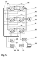
- FIG. 5 shows a fault diagnostics arrangement for an electric drive of an alternative embodiment of the invention.
- the electric drive of the invention comprises three frequency converter units 45, 46, 47 and a generator 48.
- the frequency converter units 45, 46, 47 convert the electricity produced by the generator 48 to correspond to the frequency of the mains and supply the electricity thus generated to a network 44.
- Each of the frequency converter units 45, 46, 47 of the electric drive of the invention comprises a rectifier unit, a direct voltage intermediate circuit and an inverter unit.
- Each inverter unit comprises a separate control board 51, 53, 55.
- Each rectifier unit also comprises a separate control board 52, 54, 56.
- the inverter units and rectifier units of the frequency converter units 45, 46, 47 of the electric drive of the invention are subsystems of the electric drive not separately numbered in the figure.
- the electric drive of the invention further comprises a brake chopper subsystem 49 and a liquid cooling plant subsystem 50.
- the brake chopper subsystem 49 comprises a separate control board 57 and, correspondingly, the liquid cooling plant subsystem 50 comprises a separate control board 58.
- Each control board 51 to 58 comprises a fault logger that documents all faults, warnings and other events.
- the electric drive of the invention may comprise diverse other subsystems, some of which are not involved in the motor control. Each of these subsystems typically has also a separate subsystem-specific control board and a separate fault logger data file of the control board.
- the electric drive fault diagnostics arrangement of the invention comprises a data transfer medium 40 between the control boards 51 to 58.
- the data transfer medium 40 may be a communication bus 40, such as a serial communication bus 40 or an Ethernet-based communication bus 40.
- the electric drive fault diagnostics arrangement of the invention one of the control boards of the electric drive system, for example the control board 55 of a selected inverter unit serves as the main control board 55 of the electric drive system.
- the data transfer medium 40 transfers the faults of the subsystems from the control boards 51 to 54, 56 to 58 to the main control board 55 of the electric drive system, the fault logger on the main control board 55 being thus updated also with the event data of the subsystems.
- the electric drive fault diagnostics arrangement of the invention also comprises a connection means 41 enabling a field bus connection to the electric drive system for the control board 55 of the inverter unit serving as the main control board.
- the connection means 41 may enable a field bus connection to the programmable logic controller 42 and/or a connection to the computer 43 either directly or over a telecommunications network, such as an Internet connection.
- FIG. 6 shows a fault diagnostics arrangement for an electric drive according to a second alternative embodiment of the invention.
- the electric drive of the invention comprises three frequency converter units 60, 61, 62 and a generator 63.
- the frequency converter units 60, 61, 62 convert the electricity produced by the generator 63 to correspond to the frequency of the mains and supply the electricity thus generated to the network 59.
- Each of the frequency converter units 60, 61, 62 of the electric drive of the invention comprises a rectifier unit, a direct voltage intermediate circuit and an inverter unit.
- Each inverter unit comprises a separate control board 66, 68, 70.
- Each rectifier unit also comprises a separate control board 67, 69, 71.
- the inverter units and rectifier units of the frequency converters 60, 61, 62 of the electric drive of the invention are subsystems of the electric drive not separately numbered in the figure.
- the electric drive of the invention further comprises a brake chopper subsystem 64 and a liquid cooling plant subsystem 65.
- the brake chopper subsystem 64 comprises a separate control board 72 and, correspondingly, the liquid cooling plant subsystem 65 comprises a separate control board 73.
- Each control board 66 to 73 comprises a fault logger that documents all faults, warnings and other events.
- the electric drive of the invention may comprise diverse other subsystems, some of which are not involved in the motor control. Each of these subsystems typically has also a separate subsystem-specific control board and a separate fault logger data file of the control board.
- the electric drive fault diagnostics arrangement of the invention comprises a data transfer medium 40 between the control boards 66 to 73.
- the data transfer medium 40 may be a communication bus 40, such as a serial communication bus 40 or an Ethernet-based communication bus 40.
- one of the control boards of the frequency converter units 60, 61, 62 serve as frequency-converter-specific control boards 66, 68, 70.
- one of the control boards of the electric drive system for example the control board 70 of a selected inverter unit, serves as the main control board 70 of the electric drive system.
- faults detected in subsystems of the frequency converter units 60, 61, 62 are transferred from the subsystem-specific control boards, such as the control boards 67, 69, 71 of the rectifier units, to the frequency-converter-unit-specific control boards 66, 68, 70, the fault loggers on the frequency-converter-unit-specific control boards 66, 68, 70 being thus updated also with the event data of the subsystems.
- the subsystem-specific control boards such as the control boards 67, 69, 71 of the rectifier units
- the electric drive fault diagnostics arrangement of the invention also comprises a connection means 41 enabling a field bus connection to the electric drive system for the control board 70 of the inverter unit serving as the main control board.
- the connection means 41 may enable a field bus connection to the programmable logic controller 42 and/or a connection to the computer 43 either directly or over a telecommunications network, such as an Internet connection.
- Figure 7 shows the recording of faults in a fault diagnostics arrangement of an electric drive of an embodiment of the invention.
- fault data are recorded to fault loggers residing on the control boards.
- the main control board is designated by reference numeral 74, the control boards of the subsystems being designated by reference numerals 75 to 77, respectively.
- the fault logger of the main control board 74 is designated by reference numeral 78, the fault loggers of the control boards 75 to 77 of the subsystems being designated by reference numerals 79 to 81, respectively.
- the data transfer medium between the control boards 74 to 77 is designated by reference numeral 40.
- the data transfer medium 40 between the control boards 74 to 77 may consist of a plural number of separate couplings between the control boards 74 to 77, or the data transfer medium 40 may be a communication bus 40, such as a serial communication bus 40 or an Ethernet-based communication bus 40.
- the faults are recorded to the fault loggers 79 to 81 of the subsystem control boards 75 to 77 for example as follows:
- main system faults are recorded to the fault logger 78 of the main system control board 74.
- the faults recorded to the fault loggers 79 to 81 of the subsystem control boards 75 to 77 are transferred by the data transfer medium 40 to the fault logger 78 of the main system control board 74.
- the electric drive fault diagnostics arrangement of the invention allows all system faults to be presented in a chronological order in the fault logger 78 of the control board 74 for example as follows:
- the fault diagnostics messages of the subsystems are transferred to the main control board 74 as an automated system operation.
- the system is also easier to maintain.
- the fault diagnostics messages contain a time stamp of the event, i.e. of the moment when a fault was detected in a subsystem. Thanks to the invention, a new fault added to a subsystem, for example, does not generate a software change to the main control board.
- Fault texts relating to each fault, including the fault code to be transferred to the field bus, are also transferred from the subsystems to the software of the main control board 74.
- the fault code allows the program application residing on the programmable logic controller 42 and/or the computer 43 to identify the fault type.
- the subsystems 31, 34, 35, 49, 50, 64, 65 are connected together by the data transfer medium 40 consisting of a common communication bus or separate buses.
- the control boards 37 to 39, 51 to 54, 56 to 58, 67, 69, 71 to 73, 75 to 77 of the subsystems 31, 34, 35, 49, 50, 64, 65 transmit their status data rapidly to the main control board 36, 55, 70, 74 to which the connection medium 41 enabling the field bus connection is coupled.
- fault texts relating to each fault including the fault code to be transferred to the field bus by the connection medium 41, are also transferred from the control boards 37 to 39 of the subsystems 31, 34, 35, 49, 50, 64, 65 to the software of the main control board 36, 55, 70, 74.
- the fault code allows the program application residing on the programmable logic controller 42 to identify the fault type.
- a fault triggered in a subsystem 31, 34, 35, 49, 50, 64, 65 critical from the process point of view may be interlocked with the shutdown of the entire system in the software of the main control board 36, 55, 70, 74 or the programmable logic controller 42. When a less critical fault appears, the process control may continue under with the control required by the system.
- the electric drive fault diagnostics arrangement of the invention allows electric drive diagnostics to be significantly improved by transferring on the system level subsystem faults over a serial communication link or a similar data transfer method to the main control board of the system. This enables a clearly improved total management of an electric drive system.
- the solution of the invention provides a novel fault diagnostics arrangement for use in an electric drive system for different industrial electric drive applications, the fault diagnostics solution allowing a sufficiently reliable picture of a fault situation to be conveyed on the main system level of the electric drive and to significantly facilitate analysis of fault logger data in a fault examination situation, for example.
- the electric drive fault diagnostics arrangement of the invention may be applied in the energy industry in electric drives of turbines of wind power industry or in solar power industry, for example.
- the electric drive fault diagnostics arrangement of the invention is also applicable to transport vehicle engines in shipping, for example, to be used in electric drives of ship engines, and to different process and manufacturing technological equipment.
Landscapes
- Engineering & Computer Science (AREA)
- Computer Networks & Wireless Communication (AREA)
- Physics & Mathematics (AREA)
- General Physics & Mathematics (AREA)
- Automation & Control Theory (AREA)
- Control Of Multiple Motors (AREA)
- Supply And Distribution Of Alternating Current (AREA)
- Wind Motors (AREA)
- Remote Monitoring And Control Of Power-Distribution Networks (AREA)
- Inverter Devices (AREA)
Abstract
The present invention relates to industrial electric drives, such as electric drives for turbines in wind power industry or electric drives for solar power industry, and particularly to fault diagnostics for electric drive systems. In a fault diagnostics arrangement of the invention, one of the control boards (36 to 39), (51 to 58), (66 to 77) of the electric drive system serves as a main control board (36), (55), (70), (74) of the electric drive system to which event data of the subsystems (31), (33 to 35), (49 to 50), (64 to 65) are transferred from the control boards (37 to 39), (51 to 54), (56 to 58), (66 to 69) of the subsystems by means of a data transfer medium (40). The fault diagnostics solution of the invention enables to significantly facilitate the analysis of fault logger data in a fault examination situation, for example.
Description
- The invention relates to industrial electric drives, such as electric drives for turbines of wind power industry or electric drives for solar power industry, and particularly to fault diagnostics for electric drive systems.
- Industrial electric drives are used for various applications, such as transport vehicle engines, different process and manufacturing technological devices and in energy industry. As regards transport devices, electric drives may be used in underground railway service or shipping service, for example. In process and manufacturing technology electric drives may be used e.g. in conveyors, mixers or in paper machines, for instance. In energy industry electric drives may be used in turbines of wind power industry or in solar power industry, for example.
- The most common types of electric drives are direct current drives and alternating current drives. In direct current applications the current flowing through the field winding of the motor stator generates a magnetic field that is oriented perpendicular to the field generated by the armature coil. This provides a direct current motor with a torque that is easy to adjust in direct current use by changing the armature current and by maintaining a constant exciting current. In direct current use, the armature current also allows the rate of the direct current motor to be adjusted directly.
- Electric drives based on alternating current may be further divided into frequency-controlled alternating current drives, flux-vector-controlled alternating current drives and to alternating current drives using direct torque control (DTC). Of these, the alternating current drives based on flux vector control and DTC alternating current drives allow the torque of a three-phase motor to be adjusted, whereas in a frequency-controlled alternating current drive the load on the three-phase motor determines the torque.
- Prior art is disclosed in greater detail in the following, with reference to the accompanying figures in which
-
Figure 1 shows the structure of a prior art electric drive; -
Figure 2 shows the structure of an alternative prior art electric drive; and -
Figure 3 shows a fault diagnostics arrangement for a prior art electric drive. -
Figure 1 shows the structure of a prior art electric drive. The prior art electric drive comprises apower supply 1, afrequency converter 2 and aload 3. Theload 3 may be amotor 3, for example. Thefrequency converter 2 typically consists of arectifier unit 4, a direct voltageintermediate circuit 5 and aninverter unit 6. Therectifier unit 4 of thefrequency converter 2 converts alternating voltage coming frompower supply 1 to direct voltage. Thefrequency converter 2 may be rectified by a 6-pulse diode bridge, for example. The direct voltage obtained from therectifier unit 4 of thefrequency converter 2 is stored to a direct voltageintermediate circuit 5 serving as an energy storage. Typically, the direct voltageintermediate circuit 5 of thefrequency converter 2 may be implemented by means of storage capacitors. From the direct current of the direct voltageintermediate circuit 5 theinverter unit 6 of thefrequency converter 2 produces alternating current a desired frequency needed by themotor 3 representing the load. Generally, theinverter unit 6 of thefrequency converter 2 may be implemented by means of IGBTs (IGBT, Insulated-gate Bipolar Transistor), for example. -
Figure 2 shows the structure of an alternative prior art electric drive. The alternative prior art electric drive comprises apower supply 7 and a load consisting of a number ofmotors rectifier unit 11, a direct voltageintermediate circuit 12 and a number ofseparate inverter units rectifier unit 11 of the electric drive converts alternating current coming from thepower supply 7 to direct voltage, which is stored into the direct voltageintermediate circuit 12 serving as an energy storage. From the direct current of the direct voltageintermediate circuit 12 theseparate inverter units respective motors - Electric drives are generally used at relative demanding circumstances and often also for critical applications. In fact, one of the main requirements imposed on an electric drive is its operational reliability. If an electric drive is damaged in an uncontrollable manner, in the worst case also the motor representing the load and the machine itself may become damaged and cause a great cumulative damage.
- In typical prior art electric drives each device or subsystem has a separate control board to control the operation of the device or subsystem in a fault situation. In the case of a critical fault, the control board shuts the subsystem down and, when less critical faults are concerned, the control board performs a corrective action by changing the control. All faults appearing in the device or the subsystem are recorded into a fault logger of the control board.
-
Figure 3 shows a fault diagnostics arrangement for a prior art electric drive. The prior art electric drive comprises threefrequency converter units generator 20. When thegenerator 20 is running, thefrequency converter units generator 20 to correspond to the frequency of the mains and supply the electricity thus generated to anetwork 16. Each of thefrequency converter units separate control board control board control board control board - In the
frequency converter units separate control board control board control board control board control boards control boards - An element complicating the fault diagnostics arrangement of a prior art electric drive is that in addition to inverter units and rectifier units the electric drive may comprise a number of other subsystems, such as a brake chopper subsystem and/or a liquid cooling plant subsystem. In addition to these subsystems, the electric drive may comprise diverse other subsystems, some of which are not involved in the motor control. Each subsystem thus typically also has a separate subsystem-specific control board and a separate fault logger data file of the control board.
- The prior a fault diagnostics arrangement for an electric drive has some major shortcomings. In a fault examination situation, numerous connections are laborious and complicated. Moreover, the prior art fault diagnostics arrangement does not give a reliable picture of the fault situation on the main system level of the electric drive. It has been noticed that in a fault examination situation the fault logger data of the subsystem-
specific control boards 21 to 26 are difficult to analyse and place in a chronological order. In a prior art electric drive system it is difficult to conclude how the fault has emerged and advanced and also which part of the electric drive has been damaged and which not. - Consequently, there is clearly a need and demand in industrial electric drive applications for novel fault diagnostics solutions that allow a sufficiently reliable picture of a fault situation to be conveyed on the main system level of the electric drive and facilitate the analysis of fault logger data in a fault examination situation, for example.
- An object of the invention is to provide a novel fault diagnostics arrangement for an electric drive system and an electric drive system for different industrial applications.
- The fault diagnostics arrangement of the invention for an electric drive system is characterized in that the electric drive system consists of a plural number of electric drive subsystems and the fault diagnostics arrangement of the electric drive system comprises subsystem control boards, to which event data of the subsystems is stored, one of the control boards of the electric drive system serving as a main control board of the electric drive system and the event data of the subsystems are transferred to the main control board from the control boards of the subsystems by a data transfer medium.
- The electric drive system of the invention is characterized in that the electric drive system consists of a plural number of electric drive subsystems and the fault diagnostics arrangement of the electric drive system comprises subsystem control boards, to which event data of the subsystems is stored, one of the control boards of the electric drive system serving as a main control board of the electric drive system and the event data of the subsystems are transferred to the main control board from the control boards of the subsystems by a data transfer medium.
- An improved fault diagnostics arrangement for an electric drive system and an improved electric drive system for different industrial applications has now been developed. The solution is characterized by what is stated in the independent claims. Some of the preferred embodiments of the invention are disclosed in the dependent claims.
- The present invention enables to achieve a number of advantages, as will become clear from the detailed disclosure. The fault diagnostics arrangement of the invention for an electric drive allows an extremely good and reliable picture of a fault situation to be obtained on the main system level of the electric drive. In addition, with the fault diagnostics arrangement of the invention for an electric drive system enables to facilitate the analysis of the fault logger data in a fault examination situation, for example.
-
-
Figure 1 shows the structure of a prior art electric drive; -
Figure 2 shows the structure of an alternative prior art electric drive; -
Figure 3 shows a fault diagnostics arrangement for a prior art electric drive; -
Figure 4 shows a fault diagnostics arrangement for an electric drive of an embodiment of the invention; -
Figure 5 shows a fault diagnostics arrangement for an electric drive of an alternative embodiment of the invention; -
Figure 6 shows a fault diagnostics arrangement for an electric drive of a second alternative embodiment of the invention; -
Figure 7 shows the recording of faults in a fault diagnostics arrangement of an electric drive of an embodiment of the invention. -
Figures 1 to 3 are described above. In the following, some embodiments of the invention are disclosed in greater detail with reference to preferred embodiments andFigures 4 to 7 . -
Figure 4 shows a fault diagnostics arrangement for an electric drive of an embodiment of the invention. The electric drive of the invention comprises apower supply 28, afrequency converter 29 and aload 30. Theload 30 may be amotor 30, for example. Thefrequency converter 29 consists of arectifier unit 31, a direct voltageintermediate circuit 32 and aninverter unit 33. Therectifier unit 31 of thefrequency converter 29 of the electric drive of the invention converts alternating voltage coming from thepower supply 28 to direct voltage. Thefrequency converter 29 may be rectified by a 6-pulse diode bridge, for example. The direct voltage obtained from therectifier unit 31 of thefrequency converter 29 is stored to a direct voltageintermediate circuit 32 serving as an energy storage. Typically, the direct voltageintermediate circuit 32 of thefrequency converter 29 may be implemented by means of a storage capacitor. From the direct current of the direct voltageintermediate circuit 32 theinverter unit 33 of thefrequency converter 29 produces alternating current of a desired frequency as required by themotor 30 representing the load. Theinverter unit 33 of thefrequency converter 29 of the invention may be implemented by means of IGBTs (IGBT, Insulated-gate Bipolar Transistor). The electric drive of the invention further comprises abrake chopper subsystem 34 and a liquidcooling plant subsystem 35. - In the fault diagnostics arrangement of the invention for an electric drive the
inverter unit 33 comprises aseparate control board 36 and a fault logger residing on thecontrol board 36. Also therectifier unit 31 comprises aseparate control board 37 and a rectifier-unit-specific fault logger residing on thecontrol board 37. Theinverter unit 33 and therectifier unit 31 are subsystems of theelectric drive 29. Likewise, thebrake chopper subsystem 34 and the liquidcooling plant subsystem 35 compriseseparate control boards control boards - The electric drive fault diagnostics arrangement of the invention also comprises a
data transfer medium 40 between thecontrol boards 36 to 39. The data transfer medium 40 between thecontrol boards 36 to 39 may consist of a plural number of separate couplings between thecontrol boards 36 to 39, or the data transfer medium 40 may be acommunication bus 40, such as aserial communication bus 40 or an Ethernet-basedcommunication bus 40. - In the electric drive fault diagnostics arrangement of the invention one of the control boards of the electric drive system, for example the
control board 36 of theinverter unit 33 serves as themain control board 36 of the electric drive system. In the solution of the invention, the data transfer medium 40 transfers the faults of thesubsystems specific control boards 37 to 39 to themain control board 36 of the electric drive system. Consequently, in the solution of the invention the fault logger on themain control board 36 of the electric drive system is updated also with the event data of thesubsystems control board 36 of theinverter unit 33 serving as the main control board thus comprises an electric-drive-specific fault logger data file that contains the electric-drive-system-specific event data in a chronological order. Alternatively, thecontrol board 36 of theinverter unit 33 serving as the main control board comprises not only the electric-drive-system-specific fault logger data file but also an inverter-unit-specific fault logger data file. - The electric drive fault diagnostics arrangement of the invention further comprises a connection means 41 enabling a field bus connection to the electric drive system for the
control board 36 of theinverter unit 33 serving as the main control board. The connection means 41 is typically configured to enable a connection to a programmable logic controller 42 (PLC). The connection means 41 may also be configured to enable a connection to acomputer 43. The connection to thecomputer 43 enabled by the connection means 41 may be a direct connection or, alternatively, a connection implemented over a telecommunications network, such as an Internet connection. -
Figure 5 shows a fault diagnostics arrangement for an electric drive of an alternative embodiment of the invention. The electric drive of the invention comprises threefrequency converter units generator 48. When thegenerator 48 is running, thefrequency converter units generator 48 to correspond to the frequency of the mains and supply the electricity thus generated to anetwork 44. Each of thefrequency converter units separate control board separate control board frequency converter units - The electric drive of the invention further comprises a
brake chopper subsystem 49 and a liquidcooling plant subsystem 50. Thebrake chopper subsystem 49 comprises aseparate control board 57 and, correspondingly, the liquidcooling plant subsystem 50 comprises aseparate control board 58. Eachcontrol board 51 to 58 comprises a fault logger that documents all faults, warnings and other events. In addition to the subsystems described in this example, the electric drive of the invention may comprise diverse other subsystems, some of which are not involved in the motor control. Each of these subsystems typically has also a separate subsystem-specific control board and a separate fault logger data file of the control board. - In addition, the electric drive fault diagnostics arrangement of the invention comprises a
data transfer medium 40 between thecontrol boards 51 to 58. The data transfer medium 40 may be acommunication bus 40, such as aserial communication bus 40 or an Ethernet-basedcommunication bus 40. - In the electric drive fault diagnostics arrangement of the invention one of the control boards of the electric drive system, for example the
control board 55 of a selected inverter unit serves as themain control board 55 of the electric drive system. In the solution of the invention, the data transfer medium 40 transfers the faults of the subsystems from thecontrol boards 51 to 54, 56 to 58 to themain control board 55 of the electric drive system, the fault logger on themain control board 55 being thus updated also with the event data of the subsystems. The electric drive fault diagnostics arrangement of the invention also comprises a connection means 41 enabling a field bus connection to the electric drive system for thecontrol board 55 of the inverter unit serving as the main control board. The connection means 41 may enable a field bus connection to theprogrammable logic controller 42 and/or a connection to thecomputer 43 either directly or over a telecommunications network, such as an Internet connection. -
Figure 6 shows a fault diagnostics arrangement for an electric drive according to a second alternative embodiment of the invention. The electric drive of the invention comprises threefrequency converter units generator 63. When thegenerator 63 is running, thefrequency converter units generator 63 to correspond to the frequency of the mains and supply the electricity thus generated to thenetwork 59. Each of thefrequency converter units separate control board separate control board frequency converters - The electric drive of the invention further comprises a
brake chopper subsystem 64 and a liquidcooling plant subsystem 65. Thebrake chopper subsystem 64 comprises aseparate control board 72 and, correspondingly, the liquidcooling plant subsystem 65 comprises aseparate control board 73. Eachcontrol board 66 to 73 comprises a fault logger that documents all faults, warnings and other events. In addition to the subsystems described in this example, the electric drive of the invention may comprise diverse other subsystems, some of which are not involved in the motor control. Each of these subsystems typically has also a separate subsystem-specific control board and a separate fault logger data file of the control board. - In addition, the electric drive fault diagnostics arrangement of the invention comprises a
data transfer medium 40 between thecontrol boards 66 to 73. The data transfer medium 40 may be acommunication bus 40, such as aserial communication bus 40 or an Ethernet-basedcommunication bus 40. - In the electric drive fault diagnostics system according to the second alternative embodiment of the invention one of the control boards of the
frequency converter units control boards specific control boards control board 70 of a selected inverter unit, serves as themain control board 70 of the electric drive system. - In the electric drive fault diagnostics arrangement according to the second alternative embodiment of the invention faults detected in subsystems of the
frequency converter units control boards specific control boards specific control boards transfer medium 40 transfers the frequency-converter-unit-specific fault logger data and the fault data of other subsystems from the frequency-converter-unit-specific control boards specific control boards 72 to 73 to themain control board 70 of the electric drive system, the fault logger on themain control board 70 being thus updated also with the event data of the subsystems. The electric drive fault diagnostics arrangement of the invention also comprises a connection means 41 enabling a field bus connection to the electric drive system for thecontrol board 70 of the inverter unit serving as the main control board. The connection means 41 may enable a field bus connection to theprogrammable logic controller 42 and/or a connection to thecomputer 43 either directly or over a telecommunications network, such as an Internet connection. -
Figure 7 shows the recording of faults in a fault diagnostics arrangement of an electric drive of an embodiment of the invention. In the fault diagnostics arrangement of an electric drive of the invention, fault data are recorded to fault loggers residing on the control boards. In the figure the main control board is designated byreference numeral 74, the control boards of the subsystems being designated byreference numerals 75 to 77, respectively. Further, in the figure the fault logger of themain control board 74 is designated byreference numeral 78, the fault loggers of thecontrol boards 75 to 77 of the subsystems being designated byreference numerals 79 to 81, respectively. The data transfer medium between thecontrol boards 74 to 77 is designated byreference numeral 40. The data transfer medium 40 between thecontrol boards 74 to 77 may consist of a plural number of separate couplings between thecontrol boards 74 to 77, or the data transfer medium 40 may be acommunication bus 40, such as aserial communication bus 40 or an Ethernet-basedcommunication bus 40. - When faults appear in an electric drive according to an embodiment of the invention, the faults are recorded to the
fault loggers 79 to 81 of thesubsystem control boards 75 to 77 for example as follows: - Control board fault logger of
subsystem 1- 1 Fault OVERCURRENT
- 2 Fault CABINET TEMP
- Control board fault logger of
subsystem 2- 1 Fault OVERTEMP
- Control board fault logger of
subsystem 3- 1 Fault MOTOR PHASE
- When faults appear in an electric drive according to an embodiment of the invention, main system faults are recorded to the
fault logger 78 of the mainsystem control board 74. In addition, the faults recorded to thefault loggers 79 to 81 of thesubsystem control boards 75 to 77 are transferred by the data transfer medium 40 to thefault logger 78 of the mainsystem control board 74. The electric drive fault diagnostics arrangement of the invention allows all system faults to be presented in a chronological order in thefault logger 78 of thecontrol board 74 for example as follows: - Fault logger of the main control board
- 1 Fault OVERCURRENT
- 2
Subsystem 2 Fault OVERTEMP - 3 Fault CABINET TEMP
- 4
Subsystem 1 Fault OVERCURRENT - 5
Subsystem 1 Fault CABINET TEMP - 6
Subsystem 3 Fault MOTOR PHASE
- In the electric drive fault diagnostics arrangement of the invention the fault diagnostics messages of the subsystems are transferred to the
main control board 74 as an automated system operation. The system is also easier to maintain. Moreover, the fault diagnostics messages contain a time stamp of the event, i.e. of the moment when a fault was detected in a subsystem. Thanks to the invention, a new fault added to a subsystem, for example, does not generate a software change to the main control board. Fault texts relating to each fault, including the fault code to be transferred to the field bus, are also transferred from the subsystems to the software of themain control board 74. The fault code allows the program application residing on theprogrammable logic controller 42 and/or thecomputer 43 to identify the fault type. - In the electric drive fault diagnostics arrangement of the invention the
subsystems control boards 37 to 39, 51 to 54, 56 to 58, 67, 69, 71 to 73, 75 to 77 of thesubsystems main control board connection medium 41 enabling the field bus connection is coupled. In the electric drive fault diagnostics arrangement of the invention, fault texts relating to each fault, including the fault code to be transferred to the field bus by theconnection medium 41, are also transferred from thecontrol boards 37 to 39 of thesubsystems main control board programmable logic controller 42 to identify the fault type. - Since the statuses of the
subsystems subsystem main control board programmable logic controller 42. When a less critical fault appears, the process control may continue under with the control required by the system. - The electric drive fault diagnostics arrangement of the invention allows electric drive diagnostics to be significantly improved by transferring on the system level subsystem faults over a serial communication link or a similar data transfer method to the main control board of the system. This enables a clearly improved total management of an electric drive system.
- The solution of the invention provides a novel fault diagnostics arrangement for use in an electric drive system for different industrial electric drive applications, the fault diagnostics solution allowing a sufficiently reliable picture of a fault situation to be conveyed on the main system level of the electric drive and to significantly facilitate analysis of fault logger data in a fault examination situation, for example.
- The electric drive fault diagnostics arrangement of the invention may be applied in the energy industry in electric drives of turbines of wind power industry or in solar power industry, for example. The electric drive fault diagnostics arrangement of the invention is also applicable to transport vehicle engines in shipping, for example, to be used in electric drives of ship engines, and to different process and manufacturing technological equipment.
- A skilled person will find it obvious that, as technology advances, the basic idea of the invention may be implemented in various ways. The invention and its embodiments are thus not restricted to the above examples but may vary within the scope of the claims. In other words, different features may be omitted, modified or replaced by equivalent ones, and features disclosed in this application may be combined to provide different combinations.
Claims (15)
- A fault diagnostics arrangement for an electric drive system, the electric drive system consisting of a plural number of electric drive subsystems (31), (33 to 35), (49 to 50), (64 to 65) and the fault diagnostics arrangement of the electric drive system comprising control boards (36 to 39), (51 to 58), (66 to 77) of the subsystems (31), (33 to 35), (49 to 50), (64 to 65), event data of the subsystems (31), (33 to 35), (49 to 50), (64 to 65) being recorded to the control boards, characterized in that one of the control boards (36 to 39), (51 to 58), (66 to 77) of the electric drive system serves as a main control board (36), (55), (70), (74) of the electric drive system to which the event data of the subsystems (31), (33 to 35), (49 to 50), (64 to 65) are transferred from the control boards (37 to 39), (51 to 54), (56 to 58), (66 to 69) of the subsystems by means of a data transfer medium (40).
- A fault diagnostics arrangement according to claim 1, characterized in that the electric drive subsystems (31), (33 to 35), (49 to 50), (64 to 65) comprise one or more of the following systems:- a rectifier unit (31);- an inverter unit (33);- a brake chopper subsystem (34), (49), (64); and/or- a liquid cooling plant subsystem (35), (50), (65).
- A fault diagnostics arrangement according to claim 1 or 2, characterized in that the electric drive system comprises frequency converter units (60), (61), (62), one or more of the control boards (66 to 71) of the electric drive serving as frequency-converter-unit-specific control boards (66), (68), (70) to which event data of the subsystems of the frequency converter unit are transferred from the subsystem control boards (67), (69), (71) and from the frequency-converter-unit-specific control boards (66), (68) the frequency-converter-unit-specific event data are transferred to the main control board (70) of the electric drive system by means of the data transfer medium (40).
- A fault diagnostics arrangement according to claim 1, 2 or 3, characterized in that the data transfer medium (40) consists of a plural number of separate couplings between the control boards (36-39), (51-58), (66-77) or it is a communication bus (40), a serial communication bus (40) or an Ethernet-based communication bus (40).
- A fault diagnostics arrangement according to any one of claims 1 to 4, characterized in that the fault diagnostics arrangement comprises a connection means (41), the connection means (41) enabling a field bus connection to the electric drive system for the main control board (36), (55), (70), (74).
- A fault diagnostics arrangement according to claim 5, characterized in that the connection means 41 enables a field bus connection to a programmable logic controller (42) and/or a connection to a computer (43).
- A fault diagnostics arrangement according to claim 6, characterized in that the connection to the computer 43 enabled by the connection means 41 is a direct connection, a connection implemented over a telecommunications network or a connection implemented over an Internet connection.
- A fault diagnostics arrangement according to any one of claims 1 to 7, characterized in that the event data are recorded to fault loggers (79 to 81) of the control boards (36 to 39), (51 to 58), (66 to 77).
- A fault diagnostics arrangement according to any one claims 1 to 8, characterized in that the event data also contain a time stamp of the moment when a fault was detected.
- A fault diagnostics arrangement according to any one of claims 1 to 9, characterized in that the event data contain a fault code that enables the programmable logic controller (42) and/or the computer (43) to identify the fault type.
- A fault diagnostics arrangement according to any one of claims 1 to 10, characterized in that on the basis of the event data the programmable logic controller (42) and/or the computer (43) is able to shut down the system or provide the system with the required control.
- A fault diagnostics arrangement according to any one of claims 1 to 11, characterized in that the fault diagnostics arrangement is applied to electric drives of turbines in the wind power industry.
- A fault diagnostics arrangement according to any one of claims 1 to 11, characterized in that the fault diagnostics arrangement is applied to electric drives of solar power industry.
- A fault diagnostics arrangement according to any one of claims 1 to 11, characterized in that the fault diagnostics arrangement is applied to electric drives of ship engines.
- An electric drive system consisting of a plural number of electric drive subsystems (31), (33 to 35), (49 to 50), (64 to 65), whose fault diagnostics arrangement comprises control boards (36 to 39), (51 to 58), (66 to 77) of the subsystems (31), (33 to 35), (49 to 50), (64 to 65), event data of the subsystems (31), (33 to 35), (49 to 50), (64 to 65) being recorded to the control boards, characterized in that one of the control boards (36 to 39), (51 to 58), (66 to 77) of the electric drive system serves as a main control board (36), (55), (70), (74) of the electric drive system to which the event data of the subsystems (31), (33 to 35), (49 to 50), (64 to 65) are transferred from the control boards (37 to 39), (51 to 54), (56 to 58), (66 to 69) of the subsystems by means of a data transfer medium (40).
Applications Claiming Priority (1)
| Application Number | Priority Date | Filing Date | Title |
|---|---|---|---|
| FI20105495A FI124147B (en) | 2010-05-07 | 2010-05-07 | Fault diagnosis arrangement for an electric power system and electric power system |
Publications (1)
| Publication Number | Publication Date |
|---|---|
| EP2385710A2 true EP2385710A2 (en) | 2011-11-09 |
Family
ID=42234280
Family Applications (1)
| Application Number | Title | Priority Date | Filing Date |
|---|---|---|---|
| EP11164880A Withdrawn EP2385710A2 (en) | 2010-05-07 | 2011-05-05 | Fault diagnostics arrangement for electric drive system, and electric drive system |
Country Status (4)
| Country | Link |
|---|---|
| US (1) | US20110276279A1 (en) |
| EP (1) | EP2385710A2 (en) |
| CN (1) | CN102323795B (en) |
| FI (1) | FI124147B (en) |
Families Citing this family (6)
| Publication number | Priority date | Publication date | Assignee | Title |
|---|---|---|---|---|
| FI122367B (en) | 2010-04-15 | 2011-12-30 | Abb Oy | Method and arrangement in connection with an electric drive system |
| WO2014178255A1 (en) * | 2013-04-30 | 2014-11-06 | 富士電機株式会社 | Controller and map file conversion device |
| DE102013208542A1 (en) * | 2013-05-08 | 2014-11-13 | Robert Bosch Gmbh | Detection of bending effects in electric drives |
| CN104238471A (en) * | 2013-06-17 | 2014-12-24 | 苏州新华软智能装备有限公司 | Distributed energy storage control system |
| FI126367B (en) | 2013-10-17 | 2016-10-31 | Abb Oy | Method and system for detecting a circuit board installed in a device |
| EP4055456A1 (en) * | 2019-11-05 | 2022-09-14 | ABB Schweiz AG | Method and apparatus for monitoring of electric drives in an industrial system |
Family Cites Families (6)
| Publication number | Priority date | Publication date | Assignee | Title |
|---|---|---|---|---|
| US6915440B2 (en) * | 2001-06-12 | 2005-07-05 | International Business Machines Corporation | Apparatus, program product and method of performing power fault analysis in a computer system |
| US7043663B1 (en) * | 2001-11-15 | 2006-05-09 | Xiotech Corporation | System and method to monitor and isolate faults in a storage area network |
| EP1371802A3 (en) * | 2002-06-12 | 2006-05-24 | Brose Schliesssysteme GmbH & Co. KG | Motor vehicle door lock with electro-mechanically actuated central locking |
| FI118286B (en) * | 2005-11-25 | 2007-09-14 | Abb Oy | Frequency converter assembly and method for operating the frequency converter assembly |
| FI122124B (en) * | 2006-07-04 | 2011-08-31 | Abb Oy | Procedure for controlling brake switch, brake switch and frequency converter |
| US8805595B2 (en) * | 2008-01-17 | 2014-08-12 | General Electric Company | Wind turbine arranged for independent operation of its components and related method and computer program |
-
2010
- 2010-05-07 FI FI20105495A patent/FI124147B/en not_active IP Right Cessation
-
2011
- 2011-05-05 EP EP11164880A patent/EP2385710A2/en not_active Withdrawn
- 2011-05-06 CN CN201110122110.1A patent/CN102323795B/en not_active Expired - Fee Related
- 2011-05-06 US US13/102,564 patent/US20110276279A1/en not_active Abandoned
Non-Patent Citations (1)
| Title |
|---|
| None |
Also Published As
| Publication number | Publication date |
|---|---|
| US20110276279A1 (en) | 2011-11-10 |
| FI20105495L (en) | 2011-11-08 |
| CN102323795B (en) | 2015-12-02 |
| CN102323795A (en) | 2012-01-18 |
| FI124147B (en) | 2014-03-31 |
| FI20105495A0 (en) | 2010-05-07 |
Similar Documents
| Publication | Publication Date | Title |
|---|---|---|
| EP2385710A2 (en) | Fault diagnostics arrangement for electric drive system, and electric drive system | |
| EP2709266B1 (en) | Voltage control in a doubly-fed induction generator wind turbine system | |
| US11938877B2 (en) | Power generation system and associated method | |
| US9306473B2 (en) | Variable rotor speed wind turbine, wind park, method of transmitting electric power and method of servicing or inspecting a variable rotor speed wind turbine | |
| CN102195551A (en) | Methods, systems and apparatus for synchronous current regulation of a five-phase machine | |
| CN103812391A (en) | Control apparatus of machine tool including feed shaft motor and main spindle motor | |
| US10186995B2 (en) | Rotating switching strategy for power converters | |
| US20160079898A1 (en) | Doubly-Fed, Variable-Speed, Dual-Voltage AC Generation and Distribution Systems | |
| CN104579078A (en) | Multiple-winding high-voltage motor drive control system having complete redundant backup function | |
| CN103872969A (en) | Electric drivetrain, and gas compression equipment including such a drivetrain | |
| US10205399B2 (en) | Switching strategy for increased efficiency of power converters | |
| US10027240B1 (en) | Ground fault isolation for power converters with silicon carbide MOSFETs | |
| Verma et al. | Converting to electric motors and adjustable speed drives: A case study of a 20,000 HP gas turbine driven compressor | |
| CN105471332A (en) | Master-slave control system of multi-winding synchronous motor | |
| CN109039165A (en) | The electric motor drive system of abnormity detection portion with electrical storage device | |
| CN104113265B (en) | The redundancy-type four-quadrant brushless dual-feed motor governing system that can take over seamlessly | |
| US9300131B2 (en) | Internal electrification scheme for power generation plants | |
| CN102449869B (en) | Improved interior electrification scheme for power plants | |
| Torres et al. | Adjustable speed drives and motor protection | |
| KR101903320B1 (en) | Multiple stator Bi-directional grid connection system | |
| Lockley et al. | IEEE Std 1566-The Need for a Large Adjustable Speed Drive Standard | |
| Krattiger et al. | Increase competitive level by replacing steam turbines with electric adjustable speed drive system | |
| EP3772149A1 (en) | Method for controlling power flow in an electrical supply network | |
| da Rocha et al. | Investigation of DC‐bus control modes and impacts on energy yield for a modular HVDC wind drive train | |
| Wade et al. | Reliability features of large load commutated inverter drives and some cautions in their application |
Legal Events
| Date | Code | Title | Description |
|---|---|---|---|
| AK | Designated contracting states |
Kind code of ref document: A2 Designated state(s): AL AT BE BG CH CY CZ DE DK EE ES FI FR GB GR HR HU IE IS IT LI LT LU LV MC MK MT NL NO PL PT RO RS SE SI SK SM TR |
|
| AX | Request for extension of the european patent |
Extension state: BA ME |
|
| PUAI | Public reference made under article 153(3) epc to a published international application that has entered the european phase |
Free format text: ORIGINAL CODE: 0009012 |
|
| STAA | Information on the status of an ep patent application or granted ep patent |
Free format text: STATUS: THE APPLICATION HAS BEEN PUBLISHED |
|
| STAA | Information on the status of an ep patent application or granted ep patent |
Free format text: STATUS: THE APPLICATION IS DEEMED TO BE WITHDRAWN |
|
| 18D | Application deemed to be withdrawn |
Effective date: 20161201 |