EP2385700A2 - Mobile terminal and operating method thereof - Google Patents
Mobile terminal and operating method thereof Download PDFInfo
- Publication number
- EP2385700A2 EP2385700A2 EP10013649A EP10013649A EP2385700A2 EP 2385700 A2 EP2385700 A2 EP 2385700A2 EP 10013649 A EP10013649 A EP 10013649A EP 10013649 A EP10013649 A EP 10013649A EP 2385700 A2 EP2385700 A2 EP 2385700A2
- Authority
- EP
- European Patent Office
- Prior art keywords
- information
- mobile terminal
- object information
- controller
- module
- Prior art date
- Legal status (The legal status is an assumption and is not a legal conclusion. Google has not performed a legal analysis and makes no representation as to the accuracy of the status listed.)
- Granted
Links
- 238000011017 operating method Methods 0.000 title claims abstract description 13
- 238000004891 communication Methods 0.000 claims abstract description 24
- 230000004044 response Effects 0.000 claims description 5
- 238000010586 diagram Methods 0.000 description 20
- 230000033001 locomotion Effects 0.000 description 20
- 238000000034 method Methods 0.000 description 15
- 230000000694 effects Effects 0.000 description 12
- 230000003190 augmentative effect Effects 0.000 description 10
- 230000006870 function Effects 0.000 description 10
- 238000001514 detection method Methods 0.000 description 9
- 230000001133 acceleration Effects 0.000 description 8
- 238000010295 mobile communication Methods 0.000 description 7
- 230000005236 sound signal Effects 0.000 description 7
- 239000000470 constituent Substances 0.000 description 5
- 239000000758 substrate Substances 0.000 description 5
- 238000005516 engineering process Methods 0.000 description 4
- 239000007787 solid Substances 0.000 description 4
- 230000008901 benefit Effects 0.000 description 2
- 230000008859 change Effects 0.000 description 2
- 238000007726 management method Methods 0.000 description 2
- 230000008569 process Effects 0.000 description 2
- 229910001220 stainless steel Inorganic materials 0.000 description 2
- 239000010935 stainless steel Substances 0.000 description 2
- 230000003068 static effect Effects 0.000 description 2
- 239000010936 titanium Substances 0.000 description 2
- RTAQQCXQSZGOHL-UHFFFAOYSA-N Titanium Chemical compound [Ti] RTAQQCXQSZGOHL-UHFFFAOYSA-N 0.000 description 1
- 230000003213 activating effect Effects 0.000 description 1
- 208000003464 asthenopia Diseases 0.000 description 1
- 230000005540 biological transmission Effects 0.000 description 1
- 238000006243 chemical reaction Methods 0.000 description 1
- 238000013500 data storage Methods 0.000 description 1
- 238000011161 development Methods 0.000 description 1
- 230000018109 developmental process Effects 0.000 description 1
- 238000006073 displacement reaction Methods 0.000 description 1
- 238000001652 electrophoretic deposition Methods 0.000 description 1
- 238000009432 framing Methods 0.000 description 1
- 238000002347 injection Methods 0.000 description 1
- 239000007924 injection Substances 0.000 description 1
- 238000001746 injection moulding Methods 0.000 description 1
- 230000003155 kinesthetic effect Effects 0.000 description 1
- 239000004973 liquid crystal related substance Substances 0.000 description 1
- 239000002184 metal Substances 0.000 description 1
- 229910052751 metal Inorganic materials 0.000 description 1
- 239000003094 microcapsule Substances 0.000 description 1
- 239000000203 mixture Substances 0.000 description 1
- 238000012544 monitoring process Methods 0.000 description 1
- 230000003287 optical effect Effects 0.000 description 1
- 230000037361 pathway Effects 0.000 description 1
- 238000009877 rendering Methods 0.000 description 1
- 229920003002 synthetic resin Polymers 0.000 description 1
- 239000000057 synthetic resin Substances 0.000 description 1
- 239000010409 thin film Substances 0.000 description 1
- 229910052719 titanium Inorganic materials 0.000 description 1
- 230000000007 visual effect Effects 0.000 description 1
Images


Classifications
-
- H—ELECTRICITY
- H04—ELECTRIC COMMUNICATION TECHNIQUE
- H04W—WIRELESS COMMUNICATION NETWORKS
- H04W4/00—Services specially adapted for wireless communication networks; Facilities therefor
- H04W4/02—Services making use of location information
- H04W4/025—Services making use of location information using location based information parameters
- H04W4/026—Services making use of location information using location based information parameters using orientation information, e.g. compass
-
- H—ELECTRICITY
- H04—ELECTRIC COMMUNICATION TECHNIQUE
- H04N—PICTORIAL COMMUNICATION, e.g. TELEVISION
- H04N21/00—Selective content distribution, e.g. interactive television or video on demand [VOD]
- H04N21/40—Client devices specifically adapted for the reception of or interaction with content, e.g. set-top-box [STB]; Operations thereof
- H04N21/41—Structure of client; Structure of client peripherals
- H04N21/422—Input-only peripherals, i.e. input devices connected to specially adapted client devices, e.g. global positioning system [GPS]
- H04N21/42202—Input-only peripherals, i.e. input devices connected to specially adapted client devices, e.g. global positioning system [GPS] environmental sensors, e.g. for detecting temperature, luminosity, pressure, earthquakes
-
- G—PHYSICS
- G01—MEASURING; TESTING
- G01C—MEASURING DISTANCES, LEVELS OR BEARINGS; SURVEYING; NAVIGATION; GYROSCOPIC INSTRUMENTS; PHOTOGRAMMETRY OR VIDEOGRAMMETRY
- G01C21/00—Navigation; Navigational instruments not provided for in groups G01C1/00 - G01C19/00
- G01C21/20—Instruments for performing navigational calculations
-
- H—ELECTRICITY
- H04—ELECTRIC COMMUNICATION TECHNIQUE
- H04N—PICTORIAL COMMUNICATION, e.g. TELEVISION
- H04N21/00—Selective content distribution, e.g. interactive television or video on demand [VOD]
- H04N21/20—Servers specifically adapted for the distribution of content, e.g. VOD servers; Operations thereof
- H04N21/25—Management operations performed by the server for facilitating the content distribution or administrating data related to end-users or client devices, e.g. end-user or client device authentication, learning user preferences for recommending movies
- H04N21/258—Client or end-user data management, e.g. managing client capabilities, user preferences or demographics, processing of multiple end-users preferences to derive collaborative data
- H04N21/25808—Management of client data
- H04N21/25841—Management of client data involving the geographical location of the client
-
- H—ELECTRICITY
- H04—ELECTRIC COMMUNICATION TECHNIQUE
- H04N—PICTORIAL COMMUNICATION, e.g. TELEVISION
- H04N21/00—Selective content distribution, e.g. interactive television or video on demand [VOD]
- H04N21/40—Client devices specifically adapted for the reception of or interaction with content, e.g. set-top-box [STB]; Operations thereof
- H04N21/41—Structure of client; Structure of client peripherals
- H04N21/414—Specialised client platforms, e.g. receiver in car or embedded in a mobile appliance
- H04N21/41407—Specialised client platforms, e.g. receiver in car or embedded in a mobile appliance embedded in a portable device, e.g. video client on a mobile phone, PDA, laptop
-
- H—ELECTRICITY
- H04—ELECTRIC COMMUNICATION TECHNIQUE
- H04N—PICTORIAL COMMUNICATION, e.g. TELEVISION
- H04N21/00—Selective content distribution, e.g. interactive television or video on demand [VOD]
- H04N21/40—Client devices specifically adapted for the reception of or interaction with content, e.g. set-top-box [STB]; Operations thereof
- H04N21/41—Structure of client; Structure of client peripherals
- H04N21/422—Input-only peripherals, i.e. input devices connected to specially adapted client devices, e.g. global positioning system [GPS]
- H04N21/4223—Cameras
-
- H—ELECTRICITY
- H04—ELECTRIC COMMUNICATION TECHNIQUE
- H04N—PICTORIAL COMMUNICATION, e.g. TELEVISION
- H04N21/00—Selective content distribution, e.g. interactive television or video on demand [VOD]
- H04N21/40—Client devices specifically adapted for the reception of or interaction with content, e.g. set-top-box [STB]; Operations thereof
- H04N21/47—End-user applications
- H04N21/472—End-user interface for requesting content, additional data or services; End-user interface for interacting with content, e.g. for content reservation or setting reminders, for requesting event notification, for manipulating displayed content
-
- H—ELECTRICITY
- H04—ELECTRIC COMMUNICATION TECHNIQUE
- H04N—PICTORIAL COMMUNICATION, e.g. TELEVISION
- H04N21/00—Selective content distribution, e.g. interactive television or video on demand [VOD]
- H04N21/60—Network structure or processes for video distribution between server and client or between remote clients; Control signalling between clients, server and network components; Transmission of management data between server and client, e.g. sending from server to client commands for recording incoming content stream; Communication details between server and client
- H04N21/65—Transmission of management data between client and server
- H04N21/658—Transmission by the client directed to the server
- H04N21/6587—Control parameters, e.g. trick play commands, viewpoint selection
-
- H—ELECTRICITY
- H04—ELECTRIC COMMUNICATION TECHNIQUE
- H04W—WIRELESS COMMUNICATION NETWORKS
- H04W64/00—Locating users or terminals or network equipment for network management purposes, e.g. mobility management
Landscapes
- Engineering & Computer Science (AREA)
- Signal Processing (AREA)
- Multimedia (AREA)
- Databases & Information Systems (AREA)
- Remote Sensing (AREA)
- Radar, Positioning & Navigation (AREA)
- Human Computer Interaction (AREA)
- Computer Graphics (AREA)
- General Engineering & Computer Science (AREA)
- Physics & Mathematics (AREA)
- Emergency Management (AREA)
- General Physics & Mathematics (AREA)
- Business, Economics & Management (AREA)
- Life Sciences & Earth Sciences (AREA)
- Biodiversity & Conservation Biology (AREA)
- Ecology (AREA)
- Automation & Control Theory (AREA)
- Environmental & Geological Engineering (AREA)
- Environmental Sciences (AREA)
- Computer Networks & Wireless Communication (AREA)
- Telephone Function (AREA)
- User Interface Of Digital Computer (AREA)
- Alarm Systems (AREA)
Abstract
Description
- This application claims the priority benefit of Korean Patent Application No.
10-2010-0042620, filed on May 6, 2010 - The present invention relates to a mobile terminal and an operating method thereof, and more particularly, to a mobile terminal capable of embodying augmented reality and an operating method of the mobile terminal.
- Mobile terminals are portable devices capable of performing voice/video calls, inputting and outputting information, and/or storing data. As the functions of mobile terminals diversify, an increasing number of mobile terminals have been equipped with various complicated functions, such as capturing photos and moving images, playing music files and moving image files, providing games, receiving broadcast programs, and providing wireless Internet services, and have thus evolved into multifunctional multimedia players.
- Most mobile terminals are equipped with cameras and are thus being used to capture photos or videos. With the help of advanced mobile camera technology, various techniques, called augmented reality techniques, have been developed for providing a view of a physical real-world environment together with additional information regarding the real-world view.
- Augmented reality is a term for the mixture of a view of a physical real world and information regarding the physical real world. Augmented reality techniques can allow users to easily obtain information regarding their surroundings with an enhanced sense of reality.
- A method is needed to provide various useful information to users through augmented reality.
- The present invention provides realizing augmented reality, and particularly, a mobile terminal capable of providing information regarding objects that are not even within a preview image and an operating method of the mobile terminal.
- According to an aspect of the present invention, there is provided a mobile terminal including a camera module; a display module configured to display a preview image provided by the camera module; a wireless communication unit configured to wirelessly communicate with an external device; and a controller configured to obtain location information of the mobile terminal through wireless communication with the external device and obtain object information of a first object displayed in the preview image based on the location information, wherein, if there exists object information of a second object that is overlapped by the first object, the controller displays an notificaion indicator indicating the existence of the object information of the second object on the display module.
- According to another aspect of the present invention, there is provided an operating method of a mobile terminal, the operating method including displaying a preview image provided by a camera module; obtaining position information of the mobile terminal; and if the position information of the mobile terminal indicates that there exists object information of a second object that is overlapped by a first object displayed in the preview image, displaying the object information of the second object and an notification indicator indicating the existence of the object information of the second object on the preview image.
- The above and other features and advantages of the present invention will become more apparent by describing in detail preferred embodiments thereof with reference to the attached drawings in which:
-
FIG. 1 illustrates a block diagram of a mobile terminal according to an exemplary embodiment of the present invention; -
FIG. 2 illustrates a front perspective view of the mobile terminal shown inFIG. 1 ; -
FIG. 3 illustrates a rear perspective view of the mobile terminal shown inFIG. 2 ; -
FIG. 4 illustrates a flowchart of an operating method of a mobile terminal, according to an exemplary embodiment of the present invention; -
FIGS. 5A and 5B illustrate diagrams for explaining the concept of the overlapping relationship between objects in a preview image; -
FIG. 6 illustrates diagrams for explaining an embodiment of how to display object information of an overlapped object; -
FIG. 7 illustrates a diagram for explaining an embodiment of how to incorporate an notification indicator into object information; -
FIG. 8 illustrates diagrams for explaining an embodiment of how to display object information on a preview image; -
FIG. 9 illustrates a diagram for explaining another embodiment of how to display object information on a preview image; -
FIG. 10 illustrates a diagram for explaining another embodiment of how to display object information on a preview image; -
FIG. 11 illustrates diagrams for explaining another embodiment of how to display object information on a preview image; -
FIG. 12 illustrates diagrams for explaining an embodiment of how to incorporate an notification indicator into an object; and -
FIG. 13 illustrates diagrams for explaining another embodiment of how to display object information on a preview image. - The present invention will hereinafter be described in detail with reference to the accompanying drawings in which exemplary embodiments of the invention are shown.
- The term 'mobile terminal', as used herein, may indicate a mobile phone, a smart phone, a laptop computer, a digital broadcast receiver, a personal digital assistant (PDA), a portable multimedia player (PMP), or a navigation device. In this disclosure, the terms 'module' and 'unit' can be used interchangeably.
-
FIG. 1 illustrates a block diagram of amobile terminal 100 according to an embodiment of the present invention. Referring toFIG. 1 , themobile terminal 100 may include awireless communication unit 110, an audio/video (A/V)input unit 120, auser input unit 130, asensing unit 140, anoutput unit 150, amemory 160, aninterface unit 170, acontroller 180, and apower supply unit 190. Here, when the above constituent elements are implemented, two or more of the constituent elements may be combined into one constituent element, or one constituent element may be divided into two or more constituent elements, if appropriate. - The
wireless communication unit 110 may include abroadcast reception module 111, amobile communication module 113, awireless internet module 115, a short-range communication module 117, and a global positioning system (GPS)module 119. - The
broadcast reception module 111 may receive broadcast signals and/or broadcast-related information from an external broadcast management server through a broadcast channel. The broadcast channel may be a satellite channel or a terrestrial channel. The broadcast management server may be a server which generates broadcast signals and/or broadcast-related information and transmits the generated broadcast signals and/or the generated broadcast-related information or may be a server which receives and then transmits previously-generated broadcast signals and/or previously-generated broadcast-related information. - The broadcast-related information may include broadcast channel information, broadcast program information and/or broadcast service provider information. The broadcast signals may include a TV broadcast signal, a radio broadcast signal, a data broadcast signal, the combination of a data broadcast signal and a TV broadcast signal or the combination of a data broadcast signal and a radio broadcast signal. The broadcast-related information may be provided to the
mobile terminal 100 through a mobile communication network. In this case, the broadcast-related information may be received by themobile communication module 113, rather than by thebroadcast reception module 111. - The
broadcast reception module 111 may receive broadcast signals using various broadcasting systems. In particular, thebroadcast reception module 111 may receive digital broadcast signals using various digital broadcasting systems. In addition, thebroadcast reception module 111 may be suitable not only for digital broadcasting systems but also for nearly all types of broadcasting systems other than digital broadcasting systems. The broadcast signal or the broadcast-related information received by thebroadcast reception module 111 may be stored in thememory 160. - The
mobile communication module 113 may transmit wireless signals to or receives wireless signals from at least one of a base station, an external terminal, and a server through a mobile communication network. The wireless signals may include various types of data according to whether themobile terminal 100 transmits/receives voice call signals, video call signals, or text/multimedia messages. - The
wireless internet module 115 may be a module for wirelessly accessing the internet. Thewireless internet module 115 may be embedded in themobile terminal 100 or may be installed in an external device. Thewireless internet module 115 may be embedded in themobile terminal 100 or may be installed in an external device. Thewireless internet module 115 may use various wireless internet technologies such as wireless local area network (WLAN), Wireless Broadband (WiBro), World Interoperability for Microwave Access (Wimax), and High Speed Downlink Packet Access (HSDPA). - The short-
range communication module 117 may be a module for short-range communication. The short-range communication module 117 may use various short-range communication techniques such as Bluetooth, radio frequency identification (RFID), infrared data association (IrDA), ultra wideband (UWB), and ZigBee. - The
GPS module 119 may receive location information from a plurality of GPS satellites. - The A/
V input unit 120 may be used to receive audio signals or video signals. The A/V input unit 120 may include acamera module 121 and amicrophone 123. Thecamera module 121 may process various image frames such as still images or moving images captured by an image sensor during a video call mode or an image capturing mode. The image frames processed by thecamera module 121 may be displayed by adisplay module 151. - The image frames processed by the
camera module 121 may be stored in thememory 160 or may be transmitted to an external device through thewireless communication unit 110. Themobile terminal 100 may include two ormore cameras 121. - The
microphone 123 may receive external audio signals during a call mode, a recording mode, or a voice recognition mode and may convert the received sound signals into electrical audio data. During the call mode, themobile communication module 113 may convert the electrical sound data into data that can be readily transmitted to a mobile communication base station, and may then output the data obtained by the conversion. Themicrophone 123 may use various noise removal algorithms to remove noise that may be generated during the reception of external sound signals. - The
user input unit 130 may generate key input data based on user input for controlling the operation of themobile terminal 100. Theuser input unit 130 may be implemented as a keypad, a dome switch, or a static pressure or capacitive touch pad which is capable of receiving a command or information by being pushed or touched by a user. Alternatively, theuser input unit 130 may be implemented as a wheel, a jog dial or wheel, or a joystick capable of receiving a command or information by being rotated. Still alternatively, theuser input unit 130 may be implemented as a finger mouse. In particular, if theuser input unit 130 is implemented as a touch pad and forms a mutual layer structure with thedisplay module 151, theuser input unit 130 and thedisplay module 151 may be collectively referred to as a touch screen. - The
sensing unit 140 may determine a current state of themobile terminal 100 such as whether themobile terminal 100 is opened or closed, the location of themobile terminal 100 and whether themobile terminal 100 is placed in contact with the user, and may generate a sensing signal for controlling the operation of themobile terminal 100. For example, when themobile terminal 100 is a slider-type mobile phone, thesensing unit 140 may determine whether themobile terminal 100 is opened or closed. In addition, thesensing unit 140 may determine whether themobile terminal 100 is powered by thepower supply unit 190 and whether theinterface unit 170 is connected to an external device. - The
sensing unit 140 may include aproximity sensor 141, apressure sensor 143 and amotion sensor 145. Theproximity sensor 141 may detect an approaching object or whether there is an object nearby themobile terminal 100 without mechanical contact. More specifically, theproximity sensor 141 may detect an approaching object based on a change in an alternating current (AC) magnetic field or a static magnetic field, or the rate of change of capacitance. Thesensing unit 140 may include two ormore detection sensors 141. - The
pressure sensor 143 may determine whether pressure is being applied to themobile terminal 100 or may measure the magnitude of pressure, if any, applied to themobile terminal 100. Thepressure sensor 143 may be installed in a certain part of themobile terminal 100 where the detection of pressure is necessary. For example, thepressure sensor 143 may be installed in thedisplay module 151. In this case, it is possible to differentiate a typical touch input from a pressure touch input, which is generated by applying greater pressure than that used to generate a typical touch input, based on a signal output by thepressure sensor 143. In addition, it is possible to determine the magnitude of pressure applied to thedisplay module 151 upon receiving a pressure touch input based on the signal output by thepressure sensor 143. - The
motion sensor 145 may determine the location and motion of themobile terminal 100 using an acceleration sensor or a gyro sensor. - In the meantime, acceleration sensors are a type of device for converting a vibration in acceleration into an electric signal. With recent developments in micro-electromechanical system (MEMS) technology, acceleration sensors have been widely used in various products for various purposes ranging from detecting large motions such as car collisions as performed in airbag systems for automobiles to detecting minute motions such as the motion of the hand as performed in gaming input devices. In general, two or more acceleration sensors representing different axial directions are incorporated into a single package. There are some cases when the detection of only one axial direction, for example, a Z-axis direction, is necessary. Thus, when an X- or Y-axis acceleration sensor, instead of a Z-axis acceleration sensor, is required, the X- or Y-axis acceleration sensor may be mounted on an additional substrate, and the additional substrate may be mounted on a main substrate.
- Gyro sensors are sensors for measuring angular velocity, and may determine the relative direction of the rotation of the
mobile terminal 100 to a reference direction. - The
output unit 150 may output audio signals, video signals and alarm signals. Theoutput unit 150 may include thedisplay module 151, anaudio output module 153, analarm module 155, and ahaptic module 157. - The
display module 151 may display various information processed by themobile terminal 100. For example, if themobile terminal 100 is in a call mode, thedisplay module 151 may display a user interface (UI) or a graphical user interface (GUI) for making or receiving a call. If themobile terminal 100 is in a video call mode or an image capturing mode, thedisplay module 151 may display a UI or a GUI for capturing or receiving images. - If the
display module 151 and theuser input unit 130 form a mutual layer structure and are thus implemented as a touch screen, thedisplay module 151 may be used not only as an output device but also as an input device capable of receiving information by being touched by the user. - If the
display module 151 is implemented as a touch screen, thedisplay module 151 may also include a touch screen panel and a touch screen panel controller. The touch screen panel is a transparent panel attached onto the exterior of themobile terminal 100 and may be connected to an internal bus of themobile terminal 100. The touch screen panel keeps monitoring whether the touch screen panel is being touched by the user. Once a touch input to the touch screen panel is received, the touch screen panel transmits a number of signals corresponding to the touch input to the touch screen panel controller. The touch screen panel controller processes the signals transmitted by the touch screen panel, and transmits the processed signals to thecontroller 180. Then, thecontroller 180 determines whether a touch input has been generated and which part of the touch screen panel has been touched based on the processed signals transmitted by the touch screen panel controller. - The
display module 151 may include electronic paper (e-paper). E-paper is a type of reflective display technology and can provide as high resolution as ordinary ink on paper, wide viewing angles, and excellent visual properties. E-paper can be implemented on various types of substrates such as a plastic, metallic or paper substrate and can display and maintain an image thereon even after power is cut off. In addition, e-paper can reduce the power consumption of themobile terminal 100 because it does not require a backlight assembly. Thedisplay module 151 may be implemented as e-paper by using electrostatic-charged hemispherical twist balls, using electrophoretic deposition, or using microcapsules. - The
display module 151 may include at least one of a liquid crystal display (LCD), a thin film transistor (TFT)-LCD, an organic light-emitting diode (OLED), a flexible display, and a three-dimensional (3D) display. Themobile terminal 100 may include two ormore display modules 151. For example, themobile terminal 100 may include an external display module (not shown) and an internal display module (not shown). - The
audio output module 153 may output audio data received by thewireless communication unit 110 during a call reception mode, a call mode, a recording mode, a voice recognition mode, or a broadcast reception mode or may output audio data present in thememory 160. In addition, theaudio output module 153 may output various sound signals associated with the functions of themobile terminal 100 such as receiving a call or a message. Theaudio output module 153 may include a speaker and a buzzer. - The
alarm module 155 may output an alarm signal indicating the occurrence of an event in themobile terminal 100. Examples of the event include receiving a call signal, receiving a message, and receiving a key signal. Examples of the alarm signal output by thealarm module 155 include an audio signal, a video signal and a vibration signal. More specifically, thealarm module 155 may output an alarm signal upon receiving an incoming call or message. In addition, thealarm module 155 may receive a key signal and may output an alarm signal as feedback to the key signal. Therefore, the user may be able to easily recognize the occurrence of an event based on an alarm signal output by thealarm module 155. An alarm signal for notifying the user of the occurrence of an event may be output not only by thealarm module 155 but also by thedisplay module 151 or theaudio output module 153. - The
haptic module 157 may provide various haptic effects (such as vibration) that can be perceived by the user. If thehaptic module 157 generates vibration as a haptic effect, the intensity and the pattern of vibration generated by thehaptic module 157 may be altered in various manners. Thehaptic module 157 may synthesize different vibration effects and may output the result of the synthesization. Alternatively, thehaptic module 157 may sequentially output different vibration effects. - The
haptic module 157 may provide various haptic effects, other than vibration, such as a haptic effect obtained using a pin array that moves perpendicularly to a contact skin surface, a haptic effect obtained by injecting or sucking in air through an injection hole or a suction hole, a haptic effect obtained by giving a stimulus to the surface of the skin, a haptic effect obtained through contact with an electrode, a haptic effect obtained using an electrostatic force, and a haptic effect obtained by realizing the sense of heat or cold using a device capable of absorbing heat or generating heat. Thehaptic module 157 may be configured to enable the user to recognize a haptic effect using the kinesthetic sense of the fingers or the arms. Themobile terminal 100 may include two or morehaptic modules 157. - The
memory 160 may store various programs necessary for the operation of thecontroller 180. In addition, thememory 160 may temporarily store various data such as a list of contacts, messages, still images, or moving images. - The
memory 160 may include at least one of a flash memory type storage medium, a hard disk type storage medium, a multimedia card micro type storage medium, a card type memory (e.g., a secure digital (SD) or extreme digital (XD) memory), a random access memory (RAM), and a read-only memory (ROM). Themobile terminal 100 may operate a web storage, which performs the functions of thememory 160 on the internet. - The
interface unit 170 may interface with an external device that can be connected to themobile terminal 100. Theinterface unit 170 may be a wired/wireless headset, an external battery charger, a wired/wireless data port, a card socket for, for example, a memory card, a subscriber identification module (SIM) card or a user identity module (UIM) card, an audio input/output (I/O) terminal, a video I/O terminal, or an earphone. Theinterface unit 170 may receive data from an external device or may be powered by an external device. Theinterface unit 170 may transmit data provided by an external device to other components in themobile terminal 100 or may transmit data provided by other components in themobile terminal 100 to an external device. - When the
mobile terminal 100 is connected to an external cradle, theinterface unit 170 may provide a path for supplying power from the external cradle to themobile terminal 100 or for transmitting various signals from the external cradle to themobile terminal 100. - The
controller 180 may control the general operation of themobile terminal 100. For example, thecontroller 180 may perform various control operations regarding making/receiving a voice call, transmitting/receiving data, or making/receiving a video call. Thecontroller 180 may include amultimedia player module 181, which plays multimedia data. Themultimedia player module 181 may be implemented as a hardware device and may be installed in thecontroller 180. Alternatively, themultimedia player module 181 may be implemented as a software program. - The
power supply unit 190 may be supplied with power by an external power source or an internal power source and may supply power to the other components in themobile terminal 100. - The
mobile terminal 100 may include a wired/wireless communication system or a satellite communication system and may thus be able to operate in a communication system capable of transmitting data in units of frames or packets. - The exterior structure of the
mobile terminal 100 will hereinafter be described in detail with reference toFIGS. 2 and3 . The present invention can be applied to nearly all types of mobile terminals such as a folder-type, a bar-type, a swing-type and a slider-type mobile terminal. However, for convenience, it is assumed that themobile terminal 100 is a bar-type mobile terminal equipped with a full touch screen. -
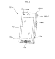
FIG. 2 illustrates a front perspective view of themobile terminal 100. Referring toFIG. 2 , the exterior of themobile terminal 100 may be formed by afront case 100A-1 and arear case 100A-2. Various electronic devices may be installed in the space formed by thefront case 100A-1 and therear case 100A-2. At least one middle case (not shown) may be additionally provided between thefront case 100A-1 1 and therear case 100A-2. Thefront case 100A-1, therear case 100A-2 and the middle case(s) may be formed of a synthetic resin through injection molding. Alternatively, thefront case 100A-1 and therear case 100A-2 may be formed of a metal such as stainless steel (STS) or titanium (Ti). - The
display module 151, a firstaudio output module 153a, afirst camera 121a, and a firstuser input module 130a may be disposed in the main body of themobile terminal 100, and particularly, in thefront case 100A-1. Second and thirduser input modules microphone 123 may be disposed on one side of therear case 100A-2. - The
display module 151 may include an LCD or OLED that can visualize information. If a touch pad is configured to overlap thedisplay module 151 and thus to form a mutual layer structure, thedisplay module 151 may serve as a touch screen. Thus, the user can enter various information simply by touching thedisplay module 151. - The first
audio output module 153a may be implemented as a receiver or a speaker. Thefirst camera 121a may be configured to be suitable for capturing a still or moving image of the user. Themicrophone 123 may be configured to properly receive the user's voice or other sounds. - The first through third
user input modules 130a through 130c and fourth and fifthuser input modules user input unit 130. Theuser input unit 130 may adopt various tactile manners as long as it can offer tactile feedback to the user. - For example, the
user input unit 130 may be implemented as a dome switch or touch pad capable of receiving a command or information by being pushed or touched by the user; or a wheel, a jog dial or wheel, or a joystick capable of receiving a command or information by being rotated. More specifically, the firstuser input module 130a may be used to enter various commands such as `start', 'end', and 'scroll' to themobile terminal 100, the seconduser input module 130b may be used to select an operating mode for themobile terminal 100, and the thirduser input module 130c may serve as a hot key for activating certain functions of themobile terminal 100. - When the
display module 151 is approached by the user's finger, theproximity sensor 141 may detect the existence of the approaching finger, and may output a proximity signal. Theproximity sensor 141 may output different proximity signals according to the distance between thedisplay module 151 and the approaching finger. For a precise detection of the approaching finger, a plurality ofproximity sensors 141 having different detection ranges may be employed. In this case, it is possible to precisely determine the distance between the approaching finger and thedisplay module 151 by comparing a plurality of proximity signals respectively provided by the plurality ofproximity sensors 141. In addition, it is possible to determine which part of thedisplay module 151 is being approached by the approaching finger and whether the approaching finger is being moved within the close vicinity of the display module 15 by determining which of the plurality ofproximity sensors 141 are outputting proximity signals. Thecontroller 180 may identify a touch key, if any, currently being approached by the approaching finger and may then control thehaptic module 157 to generate a vibration signal corresponding to the identified touch key. - When the user tilts or shakes the
mobile terminal 100, themotion sensor 145 may detect the movement of themobile terminal 100, and may generate a signal corresponding to the detected movement to thecontroller 180. Thecontroller 180 may extract various motion information such as the direction, angle, speed and intensity of the movement of themobile terminal 100 and the location of the mobile terminal 100 from the signal provided by themotion sensor 145. - The
controller 180 may keep track of the movement of themobile terminal 100 based on the extracted motion information. The type of motion information that can be extracted from the signal provided by themotion sensor 145 may vary according to the type ofmotion sensor 145. Thus, more than onemotion sensor 145 capable of providing desired motion information may be employed in themobile terminal 100. Thecontroller 180 may control themotion sensor 145 to operate only when a predetermined application is executed. -
FIG. 3 illustrates a rear perspective view of themobile terminal 100. Referring toFIG. 3 , the fourth and fifthuser input modules interface unit 170 may be disposed on one side of therear case 100A-2, and asecond camera 121b may be disposed at the back of therear case 100A-2. - The
second camera 121b may have a different photographing direction from that of thefirst camera 121a shown inFIG. 2 . In addition, the first andsecond cameras first camera 121a may be used to capture and then transmit an image of the face of the user during a video call. Thus, a low-resolution camera may be used as thefirst camera 121a. Thesecond camera 121b may be used to capture an image of an ordinary subject. In this case, the image captured by thesecond camera 121b may not need to be transmitted. Thus, a high-resolution camera may be used as thesecond camera 121b. - A
mirror 125 and acamera flash 126 may be disposed near thesecond camera 121b. Themirror 125 may be used for the user to prepare him- or herself for taking a self-portrait. Thecameral flash 126 may be used to illuminate a subject when the user attempts to capture an image of the subject with thesecond camera 121b. - A second audio output module (not shown) may be additionally provided in the
rear case 100A-2. The second audio output module may realize a stereo function along with the firstaudio output module 153a. The second audio output module may also be used in a speaker-phone mode. - Not only an antenna (not shown) for making or receiving a call but also an antenna (not shown) for receiving a broadcast signal may be disposed on one side of the
rear case 100A-2. The antennas may be installed so as to be able to be retracted from therear case 100A-2. - The
interface unit 170 may serve as a pathway for allowing themobile terminal 100 to exchange data with an external device. For example, theinterface unit 170 may include at least one of a connector for connecting earphones to the mobile terminal wiredly or wirelessly, a port for performing short-range communication, and a power supply port for supplying power to themobile terminal 100. Alternatively, theinterface unit 170 may include a card socket for receiving a SIM card, a UIM card or an exterior card such as a memory card. - The
power supply unit 190, which supplies power to themobile terminal 100, may be disposed in therear case 100A-2. The power supply unit may be a rechargeable battery and may be coupled to therear case 100A-2 so as to be attachable to or detachable from therear case 100A-2. - The
second camera 121b and the other elements that have been described as being provided in therear case 100A-2 may be provided in thefront case 100A-1. In addition, thefirst camera 121a may be configured to be rotatable and thus to cover the photographing direction of thesecond camera 121b. In this case, thesecond camera 121 b may be optional. - It will hereinafter be described in detail how to realize augmented reality with the use of the
mobile terminal 100. In the following exemplary embodiments, it will be assumed, for convenience, that thedisplay module 151 is a touch screen. -
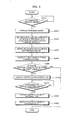
FIG. 4 illustrates a flowchart of an operating method of a mobile terminal, according to an exemplary embodiment of the present invention, and particularly, a method to provide object information of an object that is not even within a preview image. Referring toFIG. 4 , if an augmented reality mode is selected (S410), a preview image provided by thecamera module 121 may be displayed on the display module 151 (S420). More specifically, if the user selects the augmented reality mode with reference to, for example, the manual of themobile terminal 100, the preview image, which is for previewing exposure and/or framing before taking a photograph, may be displayed on thedisplay module 151. The augmented reality mode is a mode for providing a view of a physical real world and information regarding the physical real world. - Thereafter, the
controller 180 may obtain location information of themobile terminal 100 and direction information of the camera module 121 (S430). More specifically, thecontroller 180 may obtain the location information of the mobile terminal 100 from, for example, theGPS module 119, and the direction information of thecamera module 121 from, for example, a direction sensor (not shown) attached to thecamera module 121. Since thecamera module 121 is incorporated into themobile terminal 100, the location information of themobile terminal 100 may be considered to be the same as location information of thecamera module 121. - GPS information of the
mobile terminal 100 may be obtained as the location information of themobile terminal 100, but the present invention is not restricted to this. That is, thecontroller 180 may obtain the location information of themobile terminal 100 using various other methods than using theGPS module 119, for example, using Assisted GPS (A-GPS), which is a system using assistance data available from a network, using a global satellite navigation system such as Galileo or Glonass, using a Wireless Fidelity (Wi-Fi) positioning system (WPS), using cell identification (ID), which is a mobile positioning method using the cell ID of a base station where a mobile terminal bearer belongs, using Bluetooth, and using radio frequency identification (RFID). - If the
mobile terminal 100 is located in an outdoor environment, the location information of themobile terminal 100 can be obtained using theGPS module 119. On the other hand, if themobile terminal 100 is located in an indoor environment, the location information of themobile terminal 100 can be obtained using thewireless internet module 115 or the short-range communication module 117. - The direction information of the
camera module 121 can also be obtained based on the displacement in the position of themobile terminal 100 especially when themobile terminal 100 is on the move with the direction of thecamera module 121 fixed. - In this exemplary embodiment, the
controller 180 may obtain the location information of the mobile terminal 100 from thewireless communication unit 110 and the direction information of thecamera module 121 from the direction sensor attached to thecamera module 121, but the present invention is not restricted to this. That is, the user may enter initial location information and initial direction information to themobile terminal 100 through theuser input unit 130. Then, thecontroller 180 may determine the position and direction of thecamera module 121 by comparing the initial location information and the initial direction information with sensing data provided by a gyro sensor (not shown) of themobile terminal 100. - Thereafter, the
controller 180 may perform shape recognition and may thus detect one or more objects, if any, from the preview image displayed in operation 5410 (S435). There is no restriction to the type of object that that can be subjected to shape recognition. Preferably, objects of a predetermined size or greater, having object information, such as buildings, may be subjected to shape recognition. The object information may be information specifying the name, functions and origin of an object. If an object subjected to shape recognition is a building, the object information may include the name of the building, various services provided in the building and information regarding the providers of the services. - Shape recognition is a method of detecting the shape of an object that can be classified into a predefined model class from a preview image and restoring geometric information of the detected shape. Various shape recognition techniques such as control point detection or shape rendering can be used in operation 5435, but the present invention is not restricted to this.
- Operations S435 and S440 may be performed in inverse order.
- The
controller 180 may identify a first object detected from the preview image based on location information and direction information of thecamera module 121 and the results of shape recognition performed in operation S435 (S440). More specifically, thecontroller 180 may compare the location information and direction information of thecamera module 121 and the results of shape recognition performed in operation S435 with object information present in an object information database (not shown) of thememory 160. If object information (hereinafter referred to as the first object information) of the first object is not present in thememory 160, themobile terminal 100 may access an external device having its own object information database via thewireless communication unit 110 and may thus search the object information database of the external device for the first object information. In the object information database of thememory 160, object information and location information of each object may be stored in connection with each other. - In this exemplary embodiment, the detection of an object from the preview image may be performed using the location information and direction information of the
camera module 121 and the results of shape recognition performed in operation S4350, but the present invention is not restricted to this. That is, thecontroller 180 may not necessarily have to use all the location information and direction information of thecamera module 121 and the results of shape recognition performed in operation S435. Instead, thecontroller 180 may detect objects from the preview image by using at least one of the location information and direction information of thecamera module 121 and the results of shape recognition performed in operation S435. However, when using all the location information and direction information of thecamera module 121 and the results of shape recognition performed in operation S435, it is possible to enhance the precision of the detection of objects from the preview image. - Referring back to
FIG. 4 , thecontroller 180 may determine the existence of a second object which is overlapped by the first object and is thus not displayed in the preview image (S450). More specifically, the second object may be an object which stands directly behind the first object and is thus blocked from view by the first object even though being within the viewing angle of thecamera module 121. Thecontroller 180 may determine whether object information (hereinafter referred to as second object information) of the second object is present in the object information database of thememory 160. There is a restriction in the type of object that can be determined as a second object. For example, only objects having their own object information may be classified as second objects. - Given the possibility that, in reality, there are too many objects overlapped by the first object, the
controller 180 may impose a restriction on the range of objects that can be determined as second objects. For example, thecontroller 180 may consider only objects within a predetermined distance of themobile terminal 100 as possible candidates for a second object. If themobile terminal 100 is in an indoor environment, thecontroller 180 may consider only objects within the same indoor environment as themobile terminal 100 as possible candidates for a second object. - If it is determined in operation S450 that there is a second object overlapped by the first object, the
controller 180 may generate a second notification indicator indicating the existence of the second object information, and may display the second notification indicator over the preview image (S460). In order to distinguish the second notification indicator from a first notification indicator indicating the existence of the first object information, the first and second notification indicators may be displayed in different sizes or shapes, or may be displayed in connection with their respective object information. The first and second notification indicators may be displayed as icons of a certain shape or color or as symbols. - Thereafter, the
controller 180 may determine whether a command to display the second object information has been received via the user input unit 130 (S470). The user may enter the command to display the second object information by selecting the second notification indicator. - If it is determined in operation S470 that the command to display the second object information has been received, the
controller 180 may read out the second object information from the object information database in the memory 160 (S480). The second object information may be object information specifying the second object, and may include a captured image of the second object, a virtual image of the second object, text information defining the second object, an icon or symbol representing the second object, descriptions of the functions of the second object, and information regarding sub-objects included in the second object. - Thereafter, the
controller 180 may display the read-out second object information over the preview image (S490). - In this exemplary embodiment, the
controller 180 may display the second notification indicator in response to the detection of the second object, and may withdraw the second object information from thememory 160 in response to a command to display the second object information. However, the present invention is not restricted to this. That is, thecontroller 180 may withdraw the second object information from thememory 160 and may then display the second notification indicator. - The second notification indicator and the second object information may be displayed separately. Alternatively, the second object information may be displayed with, for example, a dotted outline in order to indicate that the second object information is information regarding an object overlapped by another object. In this case, the dotted outline may serve as the second notification indicator.
- It will hereinafter be described in detail how to display information regarding an object overlapped by another object in a preview image.
-
FIGS. 5A and 5B illustrate diagrams for explaining the concept of the overlapping relationship between objects in a preview image. Referring toFIG. 5A , asecond object 520 stands behind afirst object 510, and athird object 530 stands behind thesecond object 520. Referring toFIG. 5B , if the user turns thecamera module 121 toward thefirst object 510 while standing in front of thefirst object 510, thefirst object 510, which falls within aviewing angle 570 of thecamera module 121 and directly faces thecamera module 121, can be seen in a preview image provided by thecamera module 121, whereas the second andthird objects - In this case, in order to obtain information of the second or
third object first object 510, the user may bother to find his or her way to the second orthird object camera module 121 directly toward the second orthird object - Therefore, a method is needed to provide object information of objects that are not even displayed in a preview image and thus to provide information of a wider area than that displayed in the preview image.
-
FIG. 6 illustrates diagrams for explaining how to display object information of an overlapped object. For convenience, assume that there are three objects standing in line, i.e., first, second andthird objects FIG. 5A , that only thefirst object 510 can be seen in a preview image provided by thecamera module 121, and that the second andthird objects first object 510 and have their own object information. - In this case, referring to
FIG. 6(i) , first, second andthird notification indicators camera module 121. Thefirst notification indicator 610 may indicate the existence of first object information, which is object information of thefirst object 510, thesecond notification indicator 620 may indicate the existence of second object information, which is object information of thesecond object 520, and thethird notification indicator 630 may indicate the existence of third object information, which is object information of thethird object 530. Since thefirst object 510 is displayed in the preview image, thefirst notification indicator 610 may be displayed with a solid outline. On the other hand, since the second andthird objects third notification indicators - More specifically, an notification indicator for a non-overlapped object and an notification indicator for an overlapped object may differ from each other in size, color, brightness and/or grayscale. For example, an notification indicator for an overlapped object may be smaller than an notification indicator for a non-overlapped object. Alternatively, an notification indicator for an overlapped object may be darker than an notification indicator for a non-overlapped object.
- In order to obtain object information of the
second object 520, which stands behind thefirst object 510, the user may select thesecond notification indicator 620 by touching thesecond notification indicator 620. - Then, referring to
FIG. 6(ii) , asecond position indicator 640, which is an indicator of the position of thesecond object 520, andsecond object information 650, which is the object information of thesecond object 520, may be displayed on thedisplay module 151. More specifically, thesecond position indicator 640 may be displayed in order to indicate the relative position of thesecond object 520 to thefirst object 510. Thesecond position indicator 640 may be unnecessary if thesecond notification indicator 620 is suggestive enough to imply the relative position of thesecond object 520 to thefirst object 510. - A predefined amount of time after the display of the
second position indicator 640 and thesecond object information 650, thesecond position indicator 640 and thesecond object information 650 may automatically disappear from the preview image without a requirement of the receipt of a user command so that only the first, second andthird notification indicators second position indicator 640 and thesecond object information 650 may be configured to disappear from the preview image upon the receipt of a predetermined user command. In this case, the predetermined user command may be a command to display object information, other than thesecond object information 650. - In short, when there exists object information, an notification indicator may be displayed. Then, if a command to display the object information is received, the object information may be displayed in response to the received command. However, the present invention is not restricted to this. In addition, an notification indicator and/or a position indicator may be incorporated into object information.
-
FIG. 7 illustrates a diagram for explaining an embodiment of how to incorporate an notification indicator into object information. Referring toFIG. 7 , each of first, second andthird object information third object information first object information 710 is object information of a non-overlapped object, thefirst object information 710 may be displayed with a solid outline. On the other hand, since thesecond object information 720 is object information of an overlapped object, thesecond object information 720 may be displayed with a dotted outline so as to be easily distinguishable from thefirst object information 710. Alternatively, the text data of each of the first, second andthird object information - If there are many pieces of object information displayed all over a preview image, the preview image may appear distracting, and the user may get eye fatigue from looking at the preview image. In order to address this problem, object information of an object displayed in a preview image may be displayed near the corresponding object, and object information of an object overlapped by the object displayed in the preview image may be displayed on a designated part of the preview image, for example, on one side of the preview image. Alternatively, all object information may be displayed together on one side of a preview image.
-
FIG. 8 illustrates diagrams for explaining an embodiment of how to display object information on a preview image. Referring toFIG. 8(i) , assume that there are five objects (i.e., the first, second, andthird objects fifth objects 540 and 540) within a predetermined distance of themobile terminal 100, as shown inFIG. 5A , and that thecontroller 180 obtains five pieces of object information, i.e., first, second, third, fourth andfifth object information fifth objects controller 180 may display the first, second, third, fourth andfifth object information - The size of an notification indicator for object information may be determined by how many times the object information is overlapped by other object information. More specifically, since the
second object information 820 is overlapped once by thefirst object information 810 and thefifth object information 850 is overlapped once by thefourth object information 840, the size of an notification indicator for thesecond object information 820 may be the same as the size of an notification indicator for thefifth object information 850. Therefore, the user can intuitively determine that an object having thesecond object information 820 and an object having thefifth object information 850 are the same distance apart from themobile terminal 100 or are within the same entity based on the size of the notification indicators for thesecond object information 820 and thefifth object information 850. Since thethird object information 830 is overlapped twice by thefirst object information 810 and thesecond object information 820, the size of an notification indicator for thethird object information 830 may be smaller than the size of the notification indicator for thesecond object information 820. Alternatively, the size of an notification indicator may be determined by how many times an object is overlapped in a preview image. - If a command to select object information is issued in order to determine the position of a corresponding object, a position indicator indicating the position of the corresponding object may be additionally displayed on the
display module 151. For example, referring toFIGS. 8(i) and 8(ii) , if the user selects thesecond object information 820, asecond position indicator 860 indicating the position of thesecond object 520 may be displayed. - The first, second, third, fourth and
fifth object information FIG. 8 as being arranged on a preview image in descending order of distance, but the present invention is not restricted to this. That is, the first, second, third, fourth andfifth object information mobile terminal 100. -
FIG. 9 illustrates a diagram for explaining another embodiment of how to display object information on a preview image. Referring toFIG. 9 , a plurality of pieces of object information may be displayed in connection with their respective objects. Thus, the user can easily determine whether and how the plurality of pieces of object information overlap each other. In addition, sinceposition indicators - If there are too many pieces of object information to be displayed at once on the
display module 151, a scrollbar may be provided so that the object information can be effectively scrolled through. - Referring to
FIGS. 8 and9 , object information may be displayed on one side of a preview image, but the present invention is not restricted to this. That is, a preview image may be divided into a plurality of blocks, and object information may be displayed on one side of each of the blocks. Alternatively, object information may be displayed near a corresponding object in a preview image. -
FIG. 10 illustrates a diagram for explaining another embodiment of how to display object information on a preview image. Referring toFIG. 10 , a preview image may be divided vertically into two blocks, i.e., first andsecond blocks third object information first block 1010 because they are located in thefirst block 1010. Similarly,fourth object information 840 andfifth object information 850 may be displayed in thesecond block 1020 because they are located in thesecond block 1020. - Therefore, the user can roughly understand the location of an object based on where on the
display module 151 corresponding object information is displayed. - It has been described how to display object information of all objects within a predetermined distance of the
mobile terminal 100 regardless of whether the objects are non-overlapped objects or overlapped objects, but the present invention is not restricted to this. That is, object information of only non-overlapped objects may be displayed on thedisplay module 151. Object information of overlapped objects may be configured to be displayed in response to the receipt of a predetermined user command. -
FIG. 11 illustrates diagrams for explaining another embodiment of how to display object information on a preview image. Referring toFIG. 11(i) ,first object information 1110, which is object information of thefirst object 510 and also serves as an notification indicator, andsixth object information 1120, which is object information of asixth object 560 and also serves as an notification indicator, may be displayed on a preview image. Referring toFIG. 5A , thefirst object 510 stands in front of and thus overlaps the second andthird objects sixth object 560. Thus, thefirst object information 1110 may be displayed with both a solid line and a dotted line and may thus be able to be distinguished from thesixth object information 1120. - If the user touches a portion on the
display module 151 where thefirst object 510 is displayed for more than a predefined amount of time (for example, for three seconds), thecontroller 180 may determine that a command to display object information of an object overlapped by thefirst object 510 has been received. Then, thecontroller 180 may displaysecond object information 1130 on a preview image, instead of thefirst object information 1110, as shown inFIG. 11(ii) . A predefined amount of time after the display of thesecond object information 1130, thecontroller 180 may displaythird object information 1140 on the preview image, instead of thesecond object information 1130, as shown inFIG. 11(iii) . A predefined amount of time after the display of thethird object information 1140, thecontroller 180 may display thefirst object information 1110 back on the preview image, as shown inFIG. 11 (iv). - In short, referring to
FIGS. 11 (i) through 11 (iv) , a plurality of pieces of object information of overlapped objects may be displayed one after another at the same location on thedisplay module 151 throughout the duration of a touch on thedisplay module 151. Alternatively, the plurality of pieces of object information may be displayed together on thedisplay module 151 throughout the duration of a touch on thedisplay module 151. In this case, the user can easily determine the overlapping relationship between the plurality of pieces of object information. - In addition, a plurality of object information of overlapped objects may be selectively displayed according to the pressure of a touch on the
display module 151, instead of according to the duration of a touch on the,display module 151. For example, if a predetermined object is selected by a touch with a first pressure level or lower, object information of the predetermined object may be displayed. On the other hand, if the predetermined object is selected by a touch with pressure between the first pressure level and a second pressure level, object information of an object overlapped by the predetermined object may be displayed. Obviously, object information can be displayed using various touch methods, other than those set forth herein. - Referring to
FIGS. 11(i) through 11(iv) , object information into which an notification indicator is incorporated may be displayed. However, the present invention is not restricted to this. That is, an notification indicator may be incorporated into an object, instead of being incorporated into object information, and this will hereinafter be described in detail with reference toFIG. 12 . -
FIG. 12 illustrates diagrams for explaining an embodiment of how to incorporate an notification indicator into an object. Referring toFIG. 12(i) , asecond notification indicator 1210 may be displayed as a dotted line surrounding thefirst object 510. The user may enter a command to display object information of thesecond object 520, which is overlapped by thefirst object 510, by flicking thefirst object 510. Then, referring toFIG. 12(ii) , thefirst object 510 may disappear, and animage 1220 andsecond object information 1230 of thesecond object 520 may be displayed. If there is an object overlapped by thesecond object 520, athird notification indicator 1240 may be displayed as a dotted line surrounding theimage 1220. - The
image 1220 and thesecond object information 1230 may be displayed, replacing thefirst object 510, but the present invention is not restricted to this. That is, theimage 1220 and thesecond object information 1230 may be displayed over thefirst object 510, and this will hereinafter be described in detail with reference toFIG. 13 . -
FIG. 13 illustrates diagrams for explaining another embodiment of how to display object information on a preview image. Referring toFIG. 13(i) ,first object information 1310 andsecond object information 1320 may be displayed on a preview image, and an notification indicator may be incorporated into each of the first andsixth object information third objects first object 510, as shown inFIG. 5A , thefirst object information 1310 may be displayed with a solid line and a dotted line so as to be easily distinguishable from thesixth object information 1320. - In order to obtain object information of an object overlapped by the
first object 510, the user may touch a portion on thedisplay module 151 where thefirst object 510 is displayed for more than a predefined amount of time (for example, for three seconds). Then, thecontroller 180 may determine that a command to display object information of an object overlapped by thefirst object 510 has been received. A predefined amount of time later, thecontroller 180 may displaysecond object information 1330 on thedisplay module 151 together with thefirst object information 1310. A predefined amount of time after the display of thesecond object information 1330, thecontroller 180 may displaythird object information 1340 on the preview image together with thefirst object information 1310 and thesecond object information 1330, as shown inFIG. 11(iii) . A predefined amount of time after the display of thethird object information 1340, thecontroller 180 may display only thefirst object information 1110 on the preview image, as shown inFIG. 13(iv) . - A plurality of pieces of object information of overlapped objects may be selectively displayed according to the pressure of a touch on the
display module 151, instead of according to the duration of a touch on thedisplay module 151. For example, if a predetermined object is selected by a touch with a first pressure level or lower, object information of the predetermined object may be displayed. On the other hand, if the predetermined object is selected by a touch with pressure between the first pressure level and a second pressure level, object information of an object overlapped by the predetermined object may be displayed. Obviously, object information can be displayed using various touch methods, other than those set forth herein. - In this exemplary embodiment, the user can be provided with object information of an object by turning the
camera module 121 toward the object, but the present invention is not restricted to this. Once the user turns thecamera module 121 toward a predetermined object, thecontroller 180 may obtain object information of an object overlapped by the predetermined object and may store the obtained object information. Thereafter, if the user enters a command to fix a preview image, a preview image currently being displayed on thedisplay module 151 may remain unchanged even if the direction of thecamera module 121 or the location of themobile terminal 100 changes. In this case, the user can be provided with object information of an overlapped object simply by entering a predetermined command. - The mobile terminal and the operating method thereof according to the present invention are not restricted to the exemplary embodiments set forth herein. Therefore, variations and combinations of the exemplary embodiments set forth herein may fall within the scope of the present invention.
- The present invention can be realized as code that can be read by a processor (such as a mobile station modem (MSM)) included in a mobile terminal and that can be written on a computer-readable recording medium. The computer-readable recording medium may be any type of recording device in which data is stored in a computer-readable manner. Examples of the computer-readable recording medium include a ROM, a RAM, a CD-ROM, a magnetic tape, a floppy disc, an optical data storage, and a carrier wave (e.g., data transmission through the internet). The computer-readable recording medium can be distributed over a plurality of computer systems connected to a network so that computer-readable code is written thereto and executed therefrom in a decentralized manner. Functional programs, code, and code segments needed for realizing the present invention can be easily construed by one of ordinary skill in the art.
- While the present invention has been particularly shown and described with reference to exemplary embodiments thereof, it will be understood by those of ordinary skill in the art that various changes in form and details may be made therein without departing from the spirit and scope of the present invention as defined by the following claims.
Claims (15)
- A mobile terminal comprising:a camera module;a display module configured to display a preview image provided by the camera module;a wireless communication unit configured to wirelessly communicate with an external device; anda controller configured to obtain location information of the mobile terminal through wireless communication with the external device and obtain object information of a first object displayed in the preview image based on the location information, wherein, if there exists object information of a second object that is overlapped by the first object, the controller displays an indicator indicating the existence of the object information of the second object on the display module.
- The mobile terminal of claim 1, wherein the controller displays a location indicator indicating the position of the second object on the display module.
- The mobile terminal of claim 1, wherein the controller displays the object information of the second object on the display module.
- The mobile terminal of claim 3, wherein, if a command to display the object information of the second object, the controller displays the object information of the second object on the display module
- The mobile terminal of claim 3, wherein the controller makes the object information of the first object disappear when displaying the object information of the second object.
- The mobile terminal of claim 3, wherein the controller displays the object information of the second object instead of an image corresponding to the first object.
- The mobile terminal of claim 1, wherein the controller incorporates the notification indicator into the object information of the second object.
- The mobile terminal of claim 1, wherein the controller incorporates the notification indicator into the object information of the first object.
- The mobile terminal of claim 8, wherein the display module includes a touch screen and the controller displays the object information of the second object if an area on the touch screen where the first object or the object information of the first object is displayed is touched.
- The mobile terminal of claim 1, wherein the controller detects the first object using at least one of location information and direction information of the camera module and the results of the shape recognition operation on the preview image, and determines the existence of the object information of the second object based on the position information of the camera module.
- The mobile terminal of claim 1, further comprising a memory configured to include an object information database,
wherein the controller obtains the object information of the second object from the object information database. - The mobile terminal of claim 1, wherein the wireless communication unit configured to communicate with an external device having an object information database,
wherein the controller obtains the object information of the second object from the object information database through the wireless communication unit. - An operating method of a mobile terminal comprising:displaying a preview image provided by a camera module;obtaining position information of the mobile terminal; andif the position information of the mobile terminal indicates that there exists object information of a second object that is overlapped by a first object displayed in the preview image, displaying the object information of the second object and an notification indicator indicating the existence of the object information of the second object on the preview image.
- The operating method of claim 14, wherein the displaying the object information of the second object and the notification indicator comprises displaying a position indicator indicating the position of the second object.
- The operating method of claim 14, wherein the displaying the object information of the second object and the notification indicator comprises making the notification indicator disappear and displaying the object information of the second object in response to the receipt of a command to display the object information of the second object.
Applications Claiming Priority (1)
| Application Number | Priority Date | Filing Date | Title |
|---|---|---|---|
| KR1020100042620A KR101643869B1 (en) | 2010-05-06 | 2010-05-06 | Operating a Mobile Termianl with a Vibration Module |
Publications (3)
| Publication Number | Publication Date |
|---|---|
| EP2385700A2 true EP2385700A2 (en) | 2011-11-09 |
| EP2385700A3 EP2385700A3 (en) | 2013-08-07 |
| EP2385700B1 EP2385700B1 (en) | 2018-12-05 |
Family
ID=44343161
Family Applications (1)
| Application Number | Title | Priority Date | Filing Date |
|---|---|---|---|
| EP10013649.8A Active EP2385700B1 (en) | 2010-05-06 | 2010-10-14 | Mobile terminal and operating method thereof |
Country Status (3)
| Country | Link |
|---|---|
| US (1) | US8619152B2 (en) |
| EP (1) | EP2385700B1 (en) |
| KR (1) | KR101643869B1 (en) |
Families Citing this family (162)
| Publication number | Priority date | Publication date | Assignee | Title |
|---|---|---|---|---|
| US8554868B2 (en) | 2007-01-05 | 2013-10-08 | Yahoo! Inc. | Simultaneous sharing communication interface |
| DE102009037835B4 (en) | 2009-08-18 | 2012-12-06 | Metaio Gmbh | Method for displaying virtual information in a real environment |
| WO2012083106A1 (en) | 2010-12-16 | 2012-06-21 | Scion Neurostim, Llc | Combination treatments |
| KR101606727B1 (en) * | 2010-06-25 | 2016-03-28 | 엘지전자 주식회사 | Mobile terminal and operation method thereof |
| KR20120053420A (en) * | 2010-11-17 | 2012-05-25 | 삼성전자주식회사 | System and method for controlling device |
| US9531818B2 (en) * | 2011-03-01 | 2016-12-27 | Lenovo (Beijing) Limited | Information notification methods, apparatuses and electronic devices |
| KR101770262B1 (en) * | 2011-03-16 | 2017-08-22 | 엘지전자 주식회사 | Mobile terminal and control method for mobile terminal |
| US8576223B1 (en) * | 2011-03-29 | 2013-11-05 | Google Inc. | Multiple label display for 3D objects |
| US8314790B1 (en) | 2011-03-29 | 2012-11-20 | Google Inc. | Layer opacity adjustment for a three-dimensional object |
| JP5753009B2 (en) * | 2011-06-24 | 2015-07-22 | オリンパス株式会社 | Imaging device, wireless system |
| JP5802450B2 (en) * | 2011-06-24 | 2015-10-28 | オリンパス株式会社 | Imaging device, wireless system |
| MX2014000392A (en) | 2011-07-12 | 2014-04-30 | Mobli Technologies 2010 Ltd | Methods and systems of providing visual content editing functions. |
| JP5858754B2 (en) * | 2011-11-29 | 2016-02-10 | キヤノン株式会社 | Imaging apparatus, display method, and program |
| US8972357B2 (en) | 2012-02-24 | 2015-03-03 | Placed, Inc. | System and method for data collection to validate location data |
| US11734712B2 (en) | 2012-02-24 | 2023-08-22 | Foursquare Labs, Inc. | Attributing in-store visits to media consumption based on data collected from user devices |
| US10155168B2 (en) | 2012-05-08 | 2018-12-18 | Snap Inc. | System and method for adaptable avatars |
| US20130328926A1 (en) * | 2012-06-08 | 2013-12-12 | Samsung Electronics Co., Ltd | Augmented reality arrangement of nearby location information |
| TWI475474B (en) * | 2012-07-30 | 2015-03-01 | Mitac Int Corp | Gesture combined with the implementation of the icon control method |
| US20150206349A1 (en) | 2012-08-22 | 2015-07-23 | Goldrun Corporation | Augmented reality virtual content platform apparatuses, methods and systems |
| US8775972B2 (en) | 2012-11-08 | 2014-07-08 | Snapchat, Inc. | Apparatus and method for single action control of social network profile access |
| EP2936441B1 (en) * | 2012-12-21 | 2020-09-30 | Apple Inc. | Method for representing virtual information in a real environment |
| EP2936443A1 (en) * | 2012-12-21 | 2015-10-28 | Metaio GmbH | Method for representing virtual information in a real environment |
| US9959674B2 (en) * | 2013-02-26 | 2018-05-01 | Qualcomm Incorporated | Directional and X-ray view techniques for navigation using a mobile device |
| KR102003383B1 (en) * | 2013-03-14 | 2019-07-24 | 삼성전자주식회사 | Method and apparatus for shooting image in an electronic device |
| US9705831B2 (en) | 2013-05-30 | 2017-07-11 | Snap Inc. | Apparatus and method for maintaining a message thread with opt-in permanence for entries |
| US10439972B1 (en) | 2013-05-30 | 2019-10-08 | Snap Inc. | Apparatus and method for maintaining a message thread with opt-in permanence for entries |
| US9742713B2 (en) | 2013-05-30 | 2017-08-22 | Snap Inc. | Apparatus and method for maintaining a message thread with opt-in permanence for entries |
| JP2014235534A (en) * | 2013-05-31 | 2014-12-15 | 株式会社東芝 | Information processing apparatus and display control method |
| US9083770B1 (en) | 2013-11-26 | 2015-07-14 | Snapchat, Inc. | Method and system for integrating real time communication features in applications |
| CA2863124A1 (en) | 2014-01-03 | 2015-07-03 | Investel Capital Corporation | User content sharing system and method with automated external content integration |
| US9628950B1 (en) | 2014-01-12 | 2017-04-18 | Investment Asset Holdings Llc | Location-based messaging |
| US10082926B1 (en) | 2014-02-21 | 2018-09-25 | Snap Inc. | Apparatus and method for alternate channel communication initiated through a common message thread |
| US8909725B1 (en) | 2014-03-07 | 2014-12-09 | Snapchat, Inc. | Content delivery network for ephemeral objects |
| DE102014006732B4 (en) * | 2014-05-08 | 2016-12-15 | Audi Ag | Image overlay of virtual objects in a camera image |
| US9276886B1 (en) | 2014-05-09 | 2016-03-01 | Snapchat, Inc. | Apparatus and method for dynamically configuring application component tiles |
| US9396354B1 (en) | 2014-05-28 | 2016-07-19 | Snapchat, Inc. | Apparatus and method for automated privacy protection in distributed images |
| US9537811B2 (en) | 2014-10-02 | 2017-01-03 | Snap Inc. | Ephemeral gallery of ephemeral messages |
| IL239238B (en) | 2014-06-05 | 2022-04-01 | Mobli Tech 2010 Ltd | Automatic article enrichment by social media trends |
| US9113301B1 (en) | 2014-06-13 | 2015-08-18 | Snapchat, Inc. | Geo-location based event gallery |
| US9225897B1 (en) * | 2014-07-07 | 2015-12-29 | Snapchat, Inc. | Apparatus and method for supplying content aware photo filters |
| US10055717B1 (en) | 2014-08-22 | 2018-08-21 | Snap Inc. | Message processor with application prompts |
| KR102173109B1 (en) * | 2014-09-05 | 2020-11-02 | 삼성전자주식회사 | Method of processing a digital image, Computer readable storage medium of recording the method and digital photographing apparatus |
| US10423983B2 (en) | 2014-09-16 | 2019-09-24 | Snap Inc. | Determining targeting information based on a predictive targeting model |
| US10824654B2 (en) | 2014-09-18 | 2020-11-03 | Snap Inc. | Geolocation-based pictographs |
| US11216869B2 (en) | 2014-09-23 | 2022-01-04 | Snap Inc. | User interface to augment an image using geolocation |
| US10284508B1 (en) | 2014-10-02 | 2019-05-07 | Snap Inc. | Ephemeral gallery of ephemeral messages with opt-in permanence |
| US9015285B1 (en) | 2014-11-12 | 2015-04-21 | Snapchat, Inc. | User interface for accessing media at a geographic location |
| US9385983B1 (en) | 2014-12-19 | 2016-07-05 | Snapchat, Inc. | Gallery of messages from individuals with a shared interest |
| US10311916B2 (en) | 2014-12-19 | 2019-06-04 | Snap Inc. | Gallery of videos set to an audio time line |
| US9854219B2 (en) | 2014-12-19 | 2017-12-26 | Snap Inc. | Gallery of videos set to an audio time line |
| US9754355B2 (en) | 2015-01-09 | 2017-09-05 | Snap Inc. | Object recognition based photo filters |
| US11388226B1 (en) | 2015-01-13 | 2022-07-12 | Snap Inc. | Guided personal identity based actions |
| US10133705B1 (en) | 2015-01-19 | 2018-11-20 | Snap Inc. | Multichannel system |
| US9521515B2 (en) | 2015-01-26 | 2016-12-13 | Mobli Technologies 2010 Ltd. | Content request by location |
| US10223397B1 (en) | 2015-03-13 | 2019-03-05 | Snap Inc. | Social graph based co-location of network users |
| KR102371138B1 (en) | 2015-03-18 | 2022-03-10 | 스냅 인코포레이티드 | Geo-fence authorization provisioning |
| US9692967B1 (en) | 2015-03-23 | 2017-06-27 | Snap Inc. | Systems and methods for reducing boot time and power consumption in camera systems |
| US10135949B1 (en) | 2015-05-05 | 2018-11-20 | Snap Inc. | Systems and methods for story and sub-story navigation |
| US9881094B2 (en) | 2015-05-05 | 2018-01-30 | Snap Inc. | Systems and methods for automated local story generation and curation |
| US10993069B2 (en) | 2015-07-16 | 2021-04-27 | Snap Inc. | Dynamically adaptive media content delivery |
| US10817898B2 (en) | 2015-08-13 | 2020-10-27 | Placed, Llc | Determining exposures to content presented by physical objects |
| KR20170025413A (en) * | 2015-08-28 | 2017-03-08 | 엘지전자 주식회사 | Mobile terminal and method for controlling the same |
| US9652896B1 (en) | 2015-10-30 | 2017-05-16 | Snap Inc. | Image based tracking in augmented reality systems |
| US9984499B1 (en) | 2015-11-30 | 2018-05-29 | Snap Inc. | Image and point cloud based tracking and in augmented reality systems |
| US10474321B2 (en) | 2015-11-30 | 2019-11-12 | Snap Inc. | Network resource location linking and visual content sharing |
| US10354425B2 (en) | 2015-12-18 | 2019-07-16 | Snap Inc. | Method and system for providing context relevant media augmentation |
| US10679389B2 (en) | 2016-02-26 | 2020-06-09 | Snap Inc. | Methods and systems for generation, curation, and presentation of media collections |
| US11023514B2 (en) | 2016-02-26 | 2021-06-01 | Snap Inc. | Methods and systems for generation, curation, and presentation of media collections |
| US10285001B2 (en) | 2016-02-26 | 2019-05-07 | Snap Inc. | Generation, curation, and presentation of media collections |
| US10339365B2 (en) | 2016-03-31 | 2019-07-02 | Snap Inc. | Automated avatar generation |
| US11900418B2 (en) | 2016-04-04 | 2024-02-13 | Snap Inc. | Mutable geo-fencing system |
| US10466854B2 (en) * | 2016-06-10 | 2019-11-05 | Hexagon Technology Center Gmbh | Systems and methods for accessing visually obscured elements of a three-dimensional model |
| US11785161B1 (en) | 2016-06-20 | 2023-10-10 | Pipbin, Inc. | System for user accessibility of tagged curated augmented reality content |
| US10334134B1 (en) | 2016-06-20 | 2019-06-25 | Maximillian John Suiter | Augmented real estate with location and chattel tagging system and apparatus for virtual diary, scrapbooking, game play, messaging, canvasing, advertising and social interaction |
| US11876941B1 (en) | 2016-06-20 | 2024-01-16 | Pipbin, Inc. | Clickable augmented reality content manager, system, and network |
| US10638256B1 (en) | 2016-06-20 | 2020-04-28 | Pipbin, Inc. | System for distribution and display of mobile targeted augmented reality content |
| US11201981B1 (en) | 2016-06-20 | 2021-12-14 | Pipbin, Inc. | System for notification of user accessibility of curated location-dependent content in an augmented estate |
| US11044393B1 (en) | 2016-06-20 | 2021-06-22 | Pipbin, Inc. | System for curation and display of location-dependent augmented reality content in an augmented estate system |
| US10805696B1 (en) | 2016-06-20 | 2020-10-13 | Pipbin, Inc. | System for recording and targeting tagged content of user interest |
| US10430838B1 (en) | 2016-06-28 | 2019-10-01 | Snap Inc. | Methods and systems for generation, curation, and presentation of media collections with automated advertising |
| US9681265B1 (en) | 2016-06-28 | 2017-06-13 | Snap Inc. | System to track engagement of media items |
| US10387514B1 (en) | 2016-06-30 | 2019-08-20 | Snap Inc. | Automated content curation and communication |
| US10855632B2 (en) | 2016-07-19 | 2020-12-01 | Snap Inc. | Displaying customized electronic messaging graphics |
| KR102267482B1 (en) | 2016-08-30 | 2021-06-22 | 스냅 인코포레이티드 | Systems and Methods for Simultaneous Localization and Mapping |
| US10432559B2 (en) | 2016-10-24 | 2019-10-01 | Snap Inc. | Generating and displaying customized avatars in electronic messages |
| CN112738408B (en) | 2016-11-07 | 2022-09-16 | 斯纳普公司 | Selective identification and ordering of image modifiers |
| US10373358B2 (en) * | 2016-11-09 | 2019-08-06 | Sony Corporation | Edge user interface for augmenting camera viewfinder with information |
| US10203855B2 (en) | 2016-12-09 | 2019-02-12 | Snap Inc. | Customized user-controlled media overlays |
| US11616745B2 (en) | 2017-01-09 | 2023-03-28 | Snap Inc. | Contextual generation and selection of customized media content |
| US10454857B1 (en) | 2017-01-23 | 2019-10-22 | Snap Inc. | Customized digital avatar accessories |
| US10915911B2 (en) | 2017-02-03 | 2021-02-09 | Snap Inc. | System to determine a price-schedule to distribute media content |
| US10319149B1 (en) | 2017-02-17 | 2019-06-11 | Snap Inc. | Augmented reality anamorphosis system |
| US11250075B1 (en) | 2017-02-17 | 2022-02-15 | Snap Inc. | Searching social media content |
| US10074381B1 (en) | 2017-02-20 | 2018-09-11 | Snap Inc. | Augmented reality speech balloon system |
| US10565795B2 (en) | 2017-03-06 | 2020-02-18 | Snap Inc. | Virtual vision system |
| US10523625B1 (en) | 2017-03-09 | 2019-12-31 | Snap Inc. | Restricted group content collection |
| US10582277B2 (en) | 2017-03-27 | 2020-03-03 | Snap Inc. | Generating a stitched data stream |
| US10581782B2 (en) | 2017-03-27 | 2020-03-03 | Snap Inc. | Generating a stitched data stream |
| US11170393B1 (en) | 2017-04-11 | 2021-11-09 | Snap Inc. | System to calculate an engagement score of location based media content |
| US10387730B1 (en) | 2017-04-20 | 2019-08-20 | Snap Inc. | Augmented reality typography personalization system |
| US10212541B1 (en) | 2017-04-27 | 2019-02-19 | Snap Inc. | Selective location-based identity communication |
| US11893647B2 (en) | 2017-04-27 | 2024-02-06 | Snap Inc. | Location-based virtual avatars |
| KR20220141927A (en) | 2017-04-27 | 2022-10-20 | 스냅 인코포레이티드 | Location privacy management on map-based social media platforms |
| US10467147B1 (en) | 2017-04-28 | 2019-11-05 | Snap Inc. | Precaching unlockable data elements |
| US10803120B1 (en) | 2017-05-31 | 2020-10-13 | Snap Inc. | Geolocation based playlists |
| US11475254B1 (en) | 2017-09-08 | 2022-10-18 | Snap Inc. | Multimodal entity identification |
| US10740974B1 (en) | 2017-09-15 | 2020-08-11 | Snap Inc. | Augmented reality system |
| US10499191B1 (en) | 2017-10-09 | 2019-12-03 | Snap Inc. | Context sensitive presentation of content |
| US10573043B2 (en) | 2017-10-30 | 2020-02-25 | Snap Inc. | Mobile-based cartographic control of display content |
| US11265273B1 (en) | 2017-12-01 | 2022-03-01 | Snap, Inc. | Dynamic media overlay with smart widget |
| US11017173B1 (en) | 2017-12-22 | 2021-05-25 | Snap Inc. | Named entity recognition visual context and caption data |
| US10678818B2 (en) | 2018-01-03 | 2020-06-09 | Snap Inc. | Tag distribution visualization system |
| US11507614B1 (en) | 2018-02-13 | 2022-11-22 | Snap Inc. | Icon based tagging |
| US10885136B1 (en) | 2018-02-28 | 2021-01-05 | Snap Inc. | Audience filtering system |
| US10979752B1 (en) | 2018-02-28 | 2021-04-13 | Snap Inc. | Generating media content items based on location information |
| US10327096B1 (en) | 2018-03-06 | 2019-06-18 | Snap Inc. | Geo-fence selection system |
| US10933311B2 (en) | 2018-03-14 | 2021-03-02 | Snap Inc. | Generating collectible items based on location information |
| US11163941B1 (en) | 2018-03-30 | 2021-11-02 | Snap Inc. | Annotating a collection of media content items |
| US10219111B1 (en) | 2018-04-18 | 2019-02-26 | Snap Inc. | Visitation tracking system |
| US10896197B1 (en) | 2018-05-22 | 2021-01-19 | Snap Inc. | Event detection system |
| US10679393B2 (en) | 2018-07-24 | 2020-06-09 | Snap Inc. | Conditional modification of augmented reality object |
| US10997760B2 (en) | 2018-08-31 | 2021-05-04 | Snap Inc. | Augmented reality anthropomorphization system |
| US10698583B2 (en) | 2018-09-28 | 2020-06-30 | Snap Inc. | Collaborative achievement interface |
| US10778623B1 (en) | 2018-10-31 | 2020-09-15 | Snap Inc. | Messaging and gaming applications communication platform |
| US10939236B1 (en) | 2018-11-30 | 2021-03-02 | Snap Inc. | Position service to determine relative position to map features |
| US11199957B1 (en) | 2018-11-30 | 2021-12-14 | Snap Inc. | Generating customized avatars based on location information |
| US11032670B1 (en) | 2019-01-14 | 2021-06-08 | Snap Inc. | Destination sharing in location sharing system |
| US10939246B1 (en) | 2019-01-16 | 2021-03-02 | Snap Inc. | Location-based context information sharing in a messaging system |
| US11294936B1 (en) | 2019-01-30 | 2022-04-05 | Snap Inc. | Adaptive spatial density based clustering |
| US10936066B1 (en) | 2019-02-13 | 2021-03-02 | Snap Inc. | Sleep detection in a location sharing system |
| US10838599B2 (en) | 2019-02-25 | 2020-11-17 | Snap Inc. | Custom media overlay system |
| US10964082B2 (en) | 2019-02-26 | 2021-03-30 | Snap Inc. | Avatar based on weather |
| US10852918B1 (en) | 2019-03-08 | 2020-12-01 | Snap Inc. | Contextual information in chat |
| US11868414B1 (en) | 2019-03-14 | 2024-01-09 | Snap Inc. | Graph-based prediction for contact suggestion in a location sharing system |
| US11852554B1 (en) | 2019-03-21 | 2023-12-26 | Snap Inc. | Barometer calibration in a location sharing system |
| US11249614B2 (en) | 2019-03-28 | 2022-02-15 | Snap Inc. | Generating personalized map interface with enhanced icons |
| US10810782B1 (en) | 2019-04-01 | 2020-10-20 | Snap Inc. | Semantic texture mapping system |
| US10582453B1 (en) | 2019-05-30 | 2020-03-03 | Snap Inc. | Wearable device location systems architecture |
| US10560898B1 (en) | 2019-05-30 | 2020-02-11 | Snap Inc. | Wearable device location systems |
| US10893385B1 (en) | 2019-06-07 | 2021-01-12 | Snap Inc. | Detection of a physical collision between two client devices in a location sharing system |
| US11307747B2 (en) | 2019-07-11 | 2022-04-19 | Snap Inc. | Edge gesture interface with smart interactions |
| US11821742B2 (en) | 2019-09-26 | 2023-11-21 | Snap Inc. | Travel based notifications |
| US11218838B2 (en) | 2019-10-31 | 2022-01-04 | Snap Inc. | Focused map-based context information surfacing |
| US11128715B1 (en) | 2019-12-30 | 2021-09-21 | Snap Inc. | Physical friend proximity in chat |
| US10880496B1 (en) | 2019-12-30 | 2020-12-29 | Snap Inc. | Including video feed in message thread |
| US11429618B2 (en) | 2019-12-30 | 2022-08-30 | Snap Inc. | Surfacing augmented reality objects |
| US11169658B2 (en) | 2019-12-31 | 2021-11-09 | Snap Inc. | Combined map icon with action indicator |
| US11343323B2 (en) | 2019-12-31 | 2022-05-24 | Snap Inc. | Augmented reality objects registry |
| US11228551B1 (en) | 2020-02-12 | 2022-01-18 | Snap Inc. | Multiple gateway message exchange |
| US11516167B2 (en) | 2020-03-05 | 2022-11-29 | Snap Inc. | Storing data based on device location |
| US11619501B2 (en) | 2020-03-11 | 2023-04-04 | Snap Inc. | Avatar based on trip |
| US10956743B1 (en) | 2020-03-27 | 2021-03-23 | Snap Inc. | Shared augmented reality system |
| US11430091B2 (en) | 2020-03-27 | 2022-08-30 | Snap Inc. | Location mapping for large scale augmented-reality |
| US11314776B2 (en) | 2020-06-15 | 2022-04-26 | Snap Inc. | Location sharing using friend list versions |
| US11503432B2 (en) | 2020-06-15 | 2022-11-15 | Snap Inc. | Scalable real-time location sharing framework |
| US11290851B2 (en) | 2020-06-15 | 2022-03-29 | Snap Inc. | Location sharing using offline and online objects |
| US11483267B2 (en) | 2020-06-15 | 2022-10-25 | Snap Inc. | Location sharing using different rate-limited links |
| US11308327B2 (en) | 2020-06-29 | 2022-04-19 | Snap Inc. | Providing travel-based augmented reality content with a captured image |
| US11349797B2 (en) | 2020-08-31 | 2022-05-31 | Snap Inc. | Co-location connection service |
| US11606756B2 (en) | 2021-03-29 | 2023-03-14 | Snap Inc. | Scheduling requests for location data |
| US11645324B2 (en) | 2021-03-31 | 2023-05-09 | Snap Inc. | Location-based timeline media content system |
| US11829834B2 (en) | 2021-10-29 | 2023-11-28 | Snap Inc. | Extended QR code |
Family Cites Families (10)
| Publication number | Priority date | Publication date | Assignee | Title |
|---|---|---|---|---|
| KR100651508B1 (en) * | 2004-01-30 | 2006-11-29 | 삼성전자주식회사 | Method for providing local information by augmented reality and local information service system therefor |
| US7720436B2 (en) * | 2006-01-09 | 2010-05-18 | Nokia Corporation | Displaying network objects in mobile devices based on geolocation |
| US20080147730A1 (en) * | 2006-12-18 | 2008-06-19 | Motorola, Inc. | Method and system for providing location-specific image information |
| KR100838580B1 (en) | 2007-01-17 | 2008-06-20 | 한국과학기술원 | System for providing store information using cell-phone, and the method therefor |
| US8769437B2 (en) * | 2007-12-12 | 2014-07-01 | Nokia Corporation | Method, apparatus and computer program product for displaying virtual media items in a visual media |
| US9582937B2 (en) * | 2008-01-02 | 2017-02-28 | Nokia Technologies Oy | Method, apparatus and computer program product for displaying an indication of an object within a current field of view |
| KR20090132317A (en) * | 2008-06-20 | 2009-12-30 | 주식회사 케이티 | Method and system for providing additional information based on video images |
| US20090324058A1 (en) * | 2008-06-25 | 2009-12-31 | Sandage David A | Use of geographic coordinates to identify objects in images |
| US8682391B2 (en) * | 2009-08-27 | 2014-03-25 | Lg Electronics Inc. | Mobile terminal and controlling method thereof |
| US9488488B2 (en) * | 2010-02-12 | 2016-11-08 | Apple Inc. | Augmented reality maps |
-
2010
- 2010-05-06 KR KR1020100042620A patent/KR101643869B1/en active IP Right Grant
- 2010-10-14 EP EP10013649.8A patent/EP2385700B1/en active Active
- 2010-10-19 US US12/907,240 patent/US8619152B2/en active Active
Non-Patent Citations (1)
| Title |
|---|
| None |
Also Published As
| Publication number | Publication date |
|---|---|
| EP2385700B1 (en) | 2018-12-05 |
| US20110273575A1 (en) | 2011-11-10 |
| KR101643869B1 (en) | 2016-07-29 |
| EP2385700A3 (en) | 2013-08-07 |
| US8619152B2 (en) | 2013-12-31 |
| KR20110123142A (en) | 2011-11-14 |
Similar Documents
| Publication | Publication Date | Title |
|---|---|---|
| EP2385700B1 (en) | Mobile terminal and operating method thereof | |
| US8761590B2 (en) | Mobile terminal capable of providing multiplayer game and operating method thereof | |
| US8648877B2 (en) | Mobile terminal and operation method thereof | |
| US9285989B2 (en) | Mobile terminal and method of controlling the same | |
| US8935637B2 (en) | Mobile terminal and method for operating the mobile terminal | |
| US8391697B2 (en) | Mobile terminal and method of controlling the operation of the mobile terminal | |
| EP2400733B1 (en) | Mobile terminal for displaying augmented-reality information | |
| US8340695B2 (en) | Mobile terminal and method of controlling the operation of the mobile terminal | |
| US8827811B2 (en) | Mobile terminal capable of providing multiplayer game and operating method of the mobile terminal | |
| US9588609B2 (en) | Mobile terminal and method of controlling the operation of the mobile terminal | |
| US9535568B2 (en) | Mobile terminal and method of controlling the same | |
| US9513710B2 (en) | Mobile terminal for controlling various operations using a stereoscopic 3D pointer on a stereoscopic 3D image and control method thereof | |
| EP2405684B1 (en) | Mobile terminal and method for controlling the operation of the mobile terminal | |
| US8400519B2 (en) | Mobile terminal and method of controlling the operation of the mobile terminal | |
| US20110300883A1 (en) | Mobile terminal and operating method thereof | |
| US8869071B2 (en) | Mobile terminal and method of controlling the operation of the mobile terminal based on movement of a main body | |
| KR101672215B1 (en) | Mobile terminal and operation method thereof | |
| KR101651470B1 (en) | Mobile terminal and operation method thereof |
Legal Events
| Date | Code | Title | Description |
|---|---|---|---|
| AK | Designated contracting states |
Kind code of ref document: A2 Designated state(s): AL AT BE BG CH CY CZ DE DK EE ES FI FR GB GR HR HU IE IS IT LI LT LU LV MC MK MT NL NO PL PT RO RS SE SI SK SM TR |
|
| AX | Request for extension of the european patent |
Extension state: BA ME |
|
| PUAI | Public reference made under article 153(3) epc to a published international application that has entered the european phase |
Free format text: ORIGINAL CODE: 0009012 |
|
| PUAL | Search report despatched |
Free format text: ORIGINAL CODE: 0009013 |
|
| AK | Designated contracting states |
Kind code of ref document: A3 Designated state(s): AL AT BE BG CH CY CZ DE DK EE ES FI FR GB GR HR HU IE IS IT LI LT LU LV MC MK MT NL NO PL PT RO RS SE SI SK SM TR |
|
| AX | Request for extension of the european patent |
Extension state: BA ME |
|
| RIC1 | Information provided on ipc code assigned before grant |
Ipc: H04N 7/14 20060101AFI20130702BHEP |
|
| 17P | Request for examination filed |
Effective date: 20131121 |
|
| RBV | Designated contracting states (corrected) |
Designated state(s): AL AT BE BG CH CY CZ DE DK EE ES FI FR GB GR HR HU IE IS IT LI LT LU LV MC MK MT NL NO PL PT RO RS SE SI SK SM TR |
|
| 17Q | First examination report despatched |
Effective date: 20160912 |
|
| STAA | Information on the status of an ep patent application or granted ep patent |
Free format text: STATUS: EXAMINATION IS IN PROGRESS |
|
| GRAP | Despatch of communication of intention to grant a patent |
Free format text: ORIGINAL CODE: EPIDOSNIGR1 |
|
| STAA | Information on the status of an ep patent application or granted ep patent |
Free format text: STATUS: GRANT OF PATENT IS INTENDED |
|
| INTG | Intention to grant announced |
Effective date: 20180511 |
|
| RAP1 | Party data changed (applicant data changed or rights of an application transferred) |
Owner name: LG ELECTRONICS INC. |
|
| GRAS | Grant fee paid |
Free format text: ORIGINAL CODE: EPIDOSNIGR3 |
|
| GRAJ | Information related to disapproval of communication of intention to grant by the applicant or resumption of examination proceedings by the epo deleted |
Free format text: ORIGINAL CODE: EPIDOSDIGR1 |
|
| GRAL | Information related to payment of fee for publishing/printing deleted |
Free format text: ORIGINAL CODE: EPIDOSDIGR3 |
|
| STAA | Information on the status of an ep patent application or granted ep patent |
Free format text: STATUS: EXAMINATION IS IN PROGRESS |
|
| GRAP | Despatch of communication of intention to grant a patent |
Free format text: ORIGINAL CODE: EPIDOSNIGR1 |
|
| STAA | Information on the status of an ep patent application or granted ep patent |
Free format text: STATUS: GRANT OF PATENT IS INTENDED |
|
| INTC | Intention to grant announced (deleted) | ||
| GRAA | (expected) grant |
Free format text: ORIGINAL CODE: 0009210 |
|
| INTG | Intention to grant announced |
Effective date: 20181012 |
|
| GRAA | (expected) grant |
Free format text: ORIGINAL CODE: 0009210 |
|
| STAA | Information on the status of an ep patent application or granted ep patent |
Free format text: STATUS: THE PATENT HAS BEEN GRANTED |
|
| AK | Designated contracting states |
Kind code of ref document: B1 Designated state(s): AL AT BE BG CH CY CZ DE DK EE ES FI FR GB GR HR HU IE IS IT LI LT LU LV MC MK MT NL NO PL PT RO RS SE SI SK SM TR |
|
| REG | Reference to a national code |
Ref country code: GB Ref legal event code: FG4D |
|
| REG | Reference to a national code |
Ref country code: CH Ref legal event code: EP |
|
| REG | Reference to a national code |
Ref country code: AT Ref legal event code: REF Ref document number: 1074569 Country of ref document: AT Kind code of ref document: T Effective date: 20181215 |
|
| REG | Reference to a national code |
Ref country code: IE Ref legal event code: FG4D |
|
| REG | Reference to a national code |
Ref country code: DE Ref legal event code: R096 Ref document number: 602010055562 Country of ref document: DE |
|
| REG | Reference to a national code |
Ref country code: NL Ref legal event code: MP Effective date: 20181205 |
|
| REG | Reference to a national code |
Ref country code: AT Ref legal event code: MK05 Ref document number: 1074569 Country of ref document: AT Kind code of ref document: T Effective date: 20181205 |
|
| REG | Reference to a national code |
Ref country code: LT Ref legal event code: MG4D |
|
| PG25 | Lapsed in a contracting state [announced via postgrant information from national office to epo] |
Ref country code: FI Free format text: LAPSE BECAUSE OF FAILURE TO SUBMIT A TRANSLATION OF THE DESCRIPTION OR TO PAY THE FEE WITHIN THE PRESCRIBED TIME-LIMIT Effective date: 20181205 Ref country code: ES Free format text: LAPSE BECAUSE OF FAILURE TO SUBMIT A TRANSLATION OF THE DESCRIPTION OR TO PAY THE FEE WITHIN THE PRESCRIBED TIME-LIMIT Effective date: 20181205 Ref country code: BG Free format text: LAPSE BECAUSE OF FAILURE TO SUBMIT A TRANSLATION OF THE DESCRIPTION OR TO PAY THE FEE WITHIN THE PRESCRIBED TIME-LIMIT Effective date: 20190305 Ref country code: LV Free format text: LAPSE BECAUSE OF FAILURE TO SUBMIT A TRANSLATION OF THE DESCRIPTION OR TO PAY THE FEE WITHIN THE PRESCRIBED TIME-LIMIT Effective date: 20181205 Ref country code: HR Free format text: LAPSE BECAUSE OF FAILURE TO SUBMIT A TRANSLATION OF THE DESCRIPTION OR TO PAY THE FEE WITHIN THE PRESCRIBED TIME-LIMIT Effective date: 20181205 Ref country code: NO Free format text: LAPSE BECAUSE OF FAILURE TO SUBMIT A TRANSLATION OF THE DESCRIPTION OR TO PAY THE FEE WITHIN THE PRESCRIBED TIME-LIMIT Effective date: 20190305 Ref country code: LT Free format text: LAPSE BECAUSE OF FAILURE TO SUBMIT A TRANSLATION OF THE DESCRIPTION OR TO PAY THE FEE WITHIN THE PRESCRIBED TIME-LIMIT Effective date: 20181205 Ref country code: AT Free format text: LAPSE BECAUSE OF FAILURE TO SUBMIT A TRANSLATION OF THE DESCRIPTION OR TO PAY THE FEE WITHIN THE PRESCRIBED TIME-LIMIT Effective date: 20181205 |
|
| PG25 | Lapsed in a contracting state [announced via postgrant information from national office to epo] |
Ref country code: AL Free format text: LAPSE BECAUSE OF FAILURE TO SUBMIT A TRANSLATION OF THE DESCRIPTION OR TO PAY THE FEE WITHIN THE PRESCRIBED TIME-LIMIT Effective date: 20181205 Ref country code: RS Free format text: LAPSE BECAUSE OF FAILURE TO SUBMIT A TRANSLATION OF THE DESCRIPTION OR TO PAY THE FEE WITHIN THE PRESCRIBED TIME-LIMIT Effective date: 20181205 Ref country code: GR Free format text: LAPSE BECAUSE OF FAILURE TO SUBMIT A TRANSLATION OF THE DESCRIPTION OR TO PAY THE FEE WITHIN THE PRESCRIBED TIME-LIMIT Effective date: 20190306 Ref country code: SE Free format text: LAPSE BECAUSE OF FAILURE TO SUBMIT A TRANSLATION OF THE DESCRIPTION OR TO PAY THE FEE WITHIN THE PRESCRIBED TIME-LIMIT Effective date: 20181205 |
|
| PG25 | Lapsed in a contracting state [announced via postgrant information from national office to epo] |
Ref country code: NL Free format text: LAPSE BECAUSE OF FAILURE TO SUBMIT A TRANSLATION OF THE DESCRIPTION OR TO PAY THE FEE WITHIN THE PRESCRIBED TIME-LIMIT Effective date: 20181205 |
|
| PG25 | Lapsed in a contracting state [announced via postgrant information from national office to epo] |
Ref country code: PT Free format text: LAPSE BECAUSE OF FAILURE TO SUBMIT A TRANSLATION OF THE DESCRIPTION OR TO PAY THE FEE WITHIN THE PRESCRIBED TIME-LIMIT Effective date: 20190405 Ref country code: CZ Free format text: LAPSE BECAUSE OF FAILURE TO SUBMIT A TRANSLATION OF THE DESCRIPTION OR TO PAY THE FEE WITHIN THE PRESCRIBED TIME-LIMIT Effective date: 20181205 Ref country code: PL Free format text: LAPSE BECAUSE OF FAILURE TO SUBMIT A TRANSLATION OF THE DESCRIPTION OR TO PAY THE FEE WITHIN THE PRESCRIBED TIME-LIMIT Effective date: 20181205 |
|
| PG25 | Lapsed in a contracting state [announced via postgrant information from national office to epo] |
Ref country code: EE Free format text: LAPSE BECAUSE OF FAILURE TO SUBMIT A TRANSLATION OF THE DESCRIPTION OR TO PAY THE FEE WITHIN THE PRESCRIBED TIME-LIMIT Effective date: 20181205 Ref country code: SM Free format text: LAPSE BECAUSE OF FAILURE TO SUBMIT A TRANSLATION OF THE DESCRIPTION OR TO PAY THE FEE WITHIN THE PRESCRIBED TIME-LIMIT Effective date: 20181205 Ref country code: SK Free format text: LAPSE BECAUSE OF FAILURE TO SUBMIT A TRANSLATION OF THE DESCRIPTION OR TO PAY THE FEE WITHIN THE PRESCRIBED TIME-LIMIT Effective date: 20181205 Ref country code: RO Free format text: LAPSE BECAUSE OF FAILURE TO SUBMIT A TRANSLATION OF THE DESCRIPTION OR TO PAY THE FEE WITHIN THE PRESCRIBED TIME-LIMIT Effective date: 20181205 Ref country code: IS Free format text: LAPSE BECAUSE OF FAILURE TO SUBMIT A TRANSLATION OF THE DESCRIPTION OR TO PAY THE FEE WITHIN THE PRESCRIBED TIME-LIMIT Effective date: 20190405 |
|
| REG | Reference to a national code |
Ref country code: DE Ref legal event code: R097 Ref document number: 602010055562 Country of ref document: DE |
|
| PLBE | No opposition filed within time limit |
Free format text: ORIGINAL CODE: 0009261 |
|
| STAA | Information on the status of an ep patent application or granted ep patent |
Free format text: STATUS: NO OPPOSITION FILED WITHIN TIME LIMIT |
|
| PG25 | Lapsed in a contracting state [announced via postgrant information from national office to epo] |
Ref country code: SI Free format text: LAPSE BECAUSE OF FAILURE TO SUBMIT A TRANSLATION OF THE DESCRIPTION OR TO PAY THE FEE WITHIN THE PRESCRIBED TIME-LIMIT Effective date: 20181205 Ref country code: DK Free format text: LAPSE BECAUSE OF FAILURE TO SUBMIT A TRANSLATION OF THE DESCRIPTION OR TO PAY THE FEE WITHIN THE PRESCRIBED TIME-LIMIT Effective date: 20181205 |
|
| 26N | No opposition filed |
Effective date: 20190906 |
|
| PG25 | Lapsed in a contracting state [announced via postgrant information from national office to epo] |
Ref country code: TR Free format text: LAPSE BECAUSE OF FAILURE TO SUBMIT A TRANSLATION OF THE DESCRIPTION OR TO PAY THE FEE WITHIN THE PRESCRIBED TIME-LIMIT Effective date: 20181205 |
|
| PG25 | Lapsed in a contracting state [announced via postgrant information from national office to epo] |
Ref country code: MC Free format text: LAPSE BECAUSE OF FAILURE TO SUBMIT A TRANSLATION OF THE DESCRIPTION OR TO PAY THE FEE WITHIN THE PRESCRIBED TIME-LIMIT Effective date: 20181205 |
|
| REG | Reference to a national code |
Ref country code: CH Ref legal event code: PL |
|
| PG25 | Lapsed in a contracting state [announced via postgrant information from national office to epo] |
Ref country code: CH Free format text: LAPSE BECAUSE OF NON-PAYMENT OF DUE FEES Effective date: 20191031 Ref country code: LI Free format text: LAPSE BECAUSE OF NON-PAYMENT OF DUE FEES Effective date: 20191031 Ref country code: LU Free format text: LAPSE BECAUSE OF NON-PAYMENT OF DUE FEES Effective date: 20191014 |
|
| REG | Reference to a national code |
Ref country code: BE Ref legal event code: MM Effective date: 20191031 |
|
| PG25 | Lapsed in a contracting state [announced via postgrant information from national office to epo] |
Ref country code: BE Free format text: LAPSE BECAUSE OF NON-PAYMENT OF DUE FEES Effective date: 20191031 |
|
| GBPC | Gb: european patent ceased through non-payment of renewal fee |
Effective date: 20191014 |
|
| PG25 | Lapsed in a contracting state [announced via postgrant information from national office to epo] |
Ref country code: GB Free format text: LAPSE BECAUSE OF NON-PAYMENT OF DUE FEES Effective date: 20191014 Ref country code: IE Free format text: LAPSE BECAUSE OF NON-PAYMENT OF DUE FEES Effective date: 20191014 |
|
| PG25 | Lapsed in a contracting state [announced via postgrant information from national office to epo] |
Ref country code: CY Free format text: LAPSE BECAUSE OF FAILURE TO SUBMIT A TRANSLATION OF THE DESCRIPTION OR TO PAY THE FEE WITHIN THE PRESCRIBED TIME-LIMIT Effective date: 20181205 |
|
| PG25 | Lapsed in a contracting state [announced via postgrant information from national office to epo] |
Ref country code: HU Free format text: LAPSE BECAUSE OF FAILURE TO SUBMIT A TRANSLATION OF THE DESCRIPTION OR TO PAY THE FEE WITHIN THE PRESCRIBED TIME-LIMIT; INVALID AB INITIO Effective date: 20101014 Ref country code: MT Free format text: LAPSE BECAUSE OF FAILURE TO SUBMIT A TRANSLATION OF THE DESCRIPTION OR TO PAY THE FEE WITHIN THE PRESCRIBED TIME-LIMIT Effective date: 20181205 |
|
| PGFP | Annual fee paid to national office [announced via postgrant information from national office to epo] |
Ref country code: IT Payment date: 20210910 Year of fee payment: 12 |
|
| PG25 | Lapsed in a contracting state [announced via postgrant information from national office to epo] |
Ref country code: MK Free format text: LAPSE BECAUSE OF FAILURE TO SUBMIT A TRANSLATION OF THE DESCRIPTION OR TO PAY THE FEE WITHIN THE PRESCRIBED TIME-LIMIT Effective date: 20181205 |
|
| PG25 | Lapsed in a contracting state [announced via postgrant information from national office to epo] |
Ref country code: IT Free format text: LAPSE BECAUSE OF NON-PAYMENT OF DUE FEES Effective date: 20221014 |
|
| PGFP | Annual fee paid to national office [announced via postgrant information from national office to epo] |
Ref country code: FR Payment date: 20230905 Year of fee payment: 14 |
|
| PGFP | Annual fee paid to national office [announced via postgrant information from national office to epo] |
Ref country code: DE Payment date: 20230905 Year of fee payment: 14 |