EP2385385B1 - RF coil assembly for use in magnetic resonance imaging - Google Patents
RF coil assembly for use in magnetic resonance imaging Download PDFInfo
- Publication number
- EP2385385B1 EP2385385B1 EP11164243.5A EP11164243A EP2385385B1 EP 2385385 B1 EP2385385 B1 EP 2385385B1 EP 11164243 A EP11164243 A EP 11164243A EP 2385385 B1 EP2385385 B1 EP 2385385B1
- Authority
- EP
- European Patent Office
- Prior art keywords
- coil portion
- patient
- coil
- head
- lower coil
- Prior art date
- Legal status (The legal status is an assumption and is not a legal conclusion. Google has not performed a legal analysis and makes no representation as to the accuracy of the status listed.)
- Active
Links
Images




Classifications
-
- G—PHYSICS
- G01—MEASURING; TESTING
- G01R—MEASURING ELECTRIC VARIABLES; MEASURING MAGNETIC VARIABLES
- G01R33/00—Arrangements or instruments for measuring magnetic variables
- G01R33/20—Arrangements or instruments for measuring magnetic variables involving magnetic resonance
- G01R33/28—Details of apparatus provided for in groups G01R33/44 - G01R33/64
- G01R33/32—Excitation or detection systems, e.g. using radio frequency signals
- G01R33/34—Constructional details, e.g. resonators, specially adapted to MR
- G01R33/34084—Constructional details, e.g. resonators, specially adapted to MR implantable coils or coils being geometrically adaptable to the sample, e.g. flexible coils or coils comprising mutually movable parts
-
- G—PHYSICS
- G01—MEASURING; TESTING
- G01R—MEASURING ELECTRIC VARIABLES; MEASURING MAGNETIC VARIABLES
- G01R33/00—Arrangements or instruments for measuring magnetic variables
- G01R33/20—Arrangements or instruments for measuring magnetic variables involving magnetic resonance
- G01R33/28—Details of apparatus provided for in groups G01R33/44 - G01R33/64
- G01R33/32—Excitation or detection systems, e.g. using radio frequency signals
- G01R33/34—Constructional details, e.g. resonators, specially adapted to MR
- G01R33/34007—Manufacture of RF coils, e.g. using printed circuit board technology; additional hardware for providing mechanical support to the RF coil assembly or to part thereof, e.g. a support for moving the coil assembly relative to the remainder of the MR system
-
- G—PHYSICS
- G01—MEASURING; TESTING
- G01R—MEASURING ELECTRIC VARIABLES; MEASURING MAGNETIC VARIABLES
- G01R33/00—Arrangements or instruments for measuring magnetic variables
- G01R33/20—Arrangements or instruments for measuring magnetic variables involving magnetic resonance
- G01R33/28—Details of apparatus provided for in groups G01R33/44 - G01R33/64
- G01R33/32—Excitation or detection systems, e.g. using radio frequency signals
- G01R33/34—Constructional details, e.g. resonators, specially adapted to MR
- G01R33/341—Constructional details, e.g. resonators, specially adapted to MR comprising surface coils
- G01R33/3415—Constructional details, e.g. resonators, specially adapted to MR comprising surface coils comprising arrays of sub-coils, i.e. phased-array coils with flexible receiver channels
Definitions
- This invention relates to a RF coil assembly for use in magnetic resonance imaging.
- Particular aspects of the invention include a user adjustable semi-rigid flexible upper RF coil, a conformable support mechanism for the upper RF coil and a support for a lower coil.
- RF coils of various design are available for use in MR imaging.
- the coils are used to receive/transmit signal and in order to do this should be positioned directly on or immediately adjacent the human anatomy in an orientation so that the coil lies in a plane which is parallel to the axis of the bore of the magnet.
- the coils include a top portion and a bottom portion. In regard to coils for imaging the head, these are generally channel shaped and facing one another so as to envelope the head with side edges which are close or touching so that the head is surrounded by the two coil portions. Each coil portion includes an array of coil elements, typically four, so as to form a phased coil array.
- Such coils can be provided as rigid coils or as flexible foam coils.
- the rigid coils have a specific geometrical shape that can not be changed and are also usually designated for certain anatomy such as the head or chest where they are designed with the required shape to approximate to the average patient.
- Flexible coils are known and commercially available. These can be conformed to patient anatomy, but have to be held in place by using external fixation method such as straps with suitable fastening arrangements. That is the flexible coils typically can be bent into the required shape to match the anatomy, but have no ability to remain in that shape due to their elastic nature. Thus they must be fastened into place to maintain the required shape and position.
- MR imaging is carried out often in a diagnostic situation where the patient is conscious and not sterile so that the coil can be attached into place by such straps.
- flexible coils are typically or commonly used in this situation since the fastening is not a problem.
- MR imaging is carried out in an intra-operative situation where the patient is unconscious and draped to maintain sterility.
- the use of flexible coils in intra-operative applications is limited.
- typically rigid coils have been used in this situation with the coils mounted rigidly from a suitable support such as the bed frame or a head fixation device.
- Coils, whether rigid or flexible, that are used for neurosurgical applications generally have rigid attachment to the patient table or directly to the patient, which makes the mechanical/geometrical adjustment of the coil difficult or impossible.
- Such rigid coils can be sterilized as required. However they provide only a compromise in relation to the position of the coil antenna relative to the anatomy of the patient. As is well known, improved images are obtained where the antenna is located in the best position relative to the anatomy concerned and best orientation relative to the magnetic field. Thus the best images are obtained with the closest proximity combined with an orientation which is closest to parallel to the longitudinal axis of the bore, as opposed to being at an angle to the longitudinal axis. As rigid coils are necessarily sized to fit all, in many cases they do not properly fit the patient. Also the mounting typically is restrictive as to the ability to properly orient the coil.
- an apparatus for use in Magnetic Resonance imaging of a part of a patient comprising:
- the flexible material is comprised of foam.
- said at least one stiffening element is embedded in the foam.
- the coil is generally channel shaped and is movable by flexing to different curvatures.
- the coil comprises a panel member which is movable by flexing from a flat condition to different curvatures.
- the stiffening element extends transversely across the coil.
- the coil may include at least one longitudinal backbone member and the stiffening element extends at right angles to the backbone member. However this can be omitted and the coil may be stiffened only by the stiffening elements.
- stiffening members each on a respective side of the backbone, if used, member and spaced longitudinally of the backbone member.
- the stiffening member is located in a raised rib on the flexible material.
- the flexible material comprises two sheets of a foam material fastened together at a center plane of the coil with components of the coil located at the center plane and with said at least one stiffening element being embedded in one sheet.
- the upper coil portion is carried at one end of a flexible arm for movement of the upper coil to different locations relative to the patient, an opposite end of the arm being carried on a location fixed relative to the patient support table.
- the opposite end of the arm is attached to a side rail of the patient support table.
- the flexible arm is flexible along its full length.
- the flexible arm is one piece.
- the flexible arm is formed of foam with a stiffening element along the length of the arm.
- the RF coil includes a housing with a sleeve to which is attached an RF cable and wherein the flexible arm includes at said one end a clamp for engagement onto the sleeve of the housing so that the flexible arm at the housing is parallel to the RF cable.
- the RF coil includes a housing with a sleeve to which is attached an RF cable and wherein the flexible arm includes at said one end a clamp for engagement onto the sleeve of the housing and wherein the RF coil includes at least one longitudinal backbone member rigidly connected to the housing and said at least one stiffening element extends at right angles to the backbone member.
- a head clamp attached to the patient support table for holding the head of the patient stationary for an invasive procedure
- the lower r coil portion is generally channel shaped and is movable by flexing about longitudinal lines to different curvatures, and wherein the lower coil is attached at one longitudinal end to an adjustable mount connected to the head clamp and wherein the adjustable mount is adjustable to allow movement of the end of the lower coil relative to the head clamp.
- the adjustable mount is arranged after adjustment to hold the end of the lower coil at a rigidly fixed location.
- the adjustable mount provides 6 degrees of freedom of movement.
- the head clamp includes a C-shaped clamp section configured for placement of the head of the patient into it with the lower coil between the head of the patient and the C-shaped clamp section and wherein the C-shaped clamp section is arranged to engage and hold the lower coil in one of said different curvatures.
- the adjustable mount is arranged to engage the lower coil portion on a longitudinal center line of the lower coil and wherein the adjustable mount is arranged to allow movement of the center line of the lower coil to different angles and positions relative to a plane containing the C-shaped clamp section while the lower coil remains in engagement with and held by the C-shaped clamp section.
- the coil construction of the present invention is not limited to intra-operative use in imaging the head, but can be used in many MR applications such a head, neck and heart coil for both diagnostic and intra-operative modalities. It can work for extremities (e.g. legs, elbows) as well.
- extremities e.g. legs, elbows
- the arrangement described herein can provide more flexibility in use, can be user friendly and safer to use due to lack of additional conformation devices.
- the coil adjustability device described herein can allow the user to adjust the position of the coil in relation to patient anatomy without touching the patient, which will be a benefit to the patient safety. It will allow positioning the coil in the optimal way, which will increase image quality.
- the coil as described herein is built of flexible material it can allow conformation of the coil shape to the anatomy at the region of interest, this fact will improve dramatically image quality.
- the coil adjustability device described herein using adjustable semi-rigid flexible foam coil can allow the conforming to the anatomy without using any external devices, such a mechanical interfaces, straps or Velcro straps.
- Figure 1 an arrangement for carrying out Magnetic Resonance Imaging of a patient while the patient remains stationary on a patient support table.
- the arrangement provides a room in which is mounted a patient support table 10 with doors at one side of the room for entry into the room of a magnet 3 of an MR imaging system from a magnet bay.
- the table 10 described and illustrated herein is used in an arrangement where the patient remains in position on the table during surgery and while imaging is effected intra-operatively or postoperatively using MRI.
- the MR is a high-field (e.g. 1.5T or 3T) magnet that moves on overhead rails between the two or more rooms as described above.
- the arrangement may be used in a typical three room configuration with the Angiography Room (AR) on the left, a Diagnostic Room (DR) in the middle, and an Operating Room on the right.
- the magnet moves on overhead rails between the rooms and can image in each.
- the Patient Handling System or support table is indicated generally at 10.
- the patient support table includes a base of a conventional construction which allows the base to move a patient support portion to required locations in height and in orientation. Suitable drive mechanisms and couplings are known in the art and thus are not required to be described herein.
- the patient support portion At the top of the base is mounted the patient support portion in the form of a generally planar body formed of a fiber reinforced plastics material so as to define a surface area sufficient for supporting the patient while lying on the patient support portion.
- the apparatus includes a head clamp 20 which is connected onto the end of the table 10 by a mounting bracket 21.
- the details of these components are well known to a person skilled in this art and can vary so that they are not described herein.
- the head clamp includes a C-shaped clamp section and a pair of skull clamp pin members 22 and 23 which engage respective sides of the skull to hold the head in place at a fixed position for surgery and for imaging.
- the C-shaped clamp section includes a base portion 24 which is adjustable in width with a pair of upstanding arms 25 each of which carries a respective pin member 22, 23 at its upper end.
- the C-shaped clamp section is carried on a bracket 26 which includes a plurality of interconnected and adjustable arms which allow the C-shaped clamp section to be adjusted in a number of direction so that the plane of the clamp section can be moved side to side, up and down, and can be tilted around axes generally longitudinal of the patient support table and generally transverse to the patient support table.
- the clamp section 24 is tilted forwardly of a vertical plane to move the clamp pin members forwardly. It is also possible that the clamp section 24 can be rotated around an axis longitudinal to the table so that one clamp pin member is higher than the other.
- the apparatus further includes an RF coil 30 formed of top coil portion 31 and a bottom coil portion 32. These are each formed of a plurality of antennae elements so that they cooperate around the head to form a phased array.
- the top coil portion 31 is carried on a support arm 33 connected to the side rail 10A of the table 10.
- the bottom coil portion is carried on an adjustable bracket 34 which is rigid but can be adjusted so as to move the connection at the front of the bottom coil relative to the head clamp.
- a schematic illustration of the RF coil 31 is shown in Figure 4 and includes a printed circuit board 36.
- the board is formed of polyimide film (KaptonTM) which is a flexible substrate onto which the antennae are formed as conductive traces and on which are carried the various circuit components well known to be required in such coil constructions.
- the circuitry of the coil includes conductive traces 37, capacitors 38, diodes 40, and pre-amplifiers 44. All of these elements are conventional in general construction and are well known to persons skilled in the art of coil design so that detailed explanation is not required here.
- the upper and lower coil portions are basically formed in the same construction to provide a flexible arrangement to allow the coil portions to take up a generally U-shaped configuration in which the bottom of the legs of the U-shape of the top coil portion meet or lie closely adjacent the top of the legs of the bottom coil to provide the surrounding arrangement.
- the coil portion is formed of a foam flexible material 42 allowing the coil to be flexed to different shapes.
- the flexible material comprises two sheets 42A and 42B of a foam material fastened together at a center plane 43 of the coil with the components of the coil on the flexible circuit board 36 located at the center plane.
- the coil portion is movable by flexing from a flat condition to different curvatures where it is generally channel shaped and is movable by flexing to different curvatures.
- the two overlying sheets of foam material are coextensive with the board 36 spaced inwardly from the side edges.
- the components of the circuit are also embedded in the foam material.
- the thickness of the foam material is selected to allow the required degree of flexing.
- the foam material may be notched at spaced positions across the panel to localize the flexing action at preferred positions with those preferred positions being located mid way across the sections of the antenna so as to minimize bending at regions where components 38, 40 are located on the circuit board 36.
- the antennae and their pre-amplifiers connect to a central unit 44 mounted in a housing 45 at one edge of the panel.
- the housing connects to a neck 46 to which the RF cable 47 is attached to pass from the RF coil to the control system at a remote location.
- Such flexible RF coil constructions are known. Typically they have some elasticity which prevents their taking up and retaining the required shape closely surrounding the anatomy of the patient.
- the stiffening element 50 In respect of the top coil portion, in order to maintain the required shape of the panel forming the coil portion, there is provided at least one stiffening element 50 attached to the flexible foam material and movable therewith.
- the stiffening elements 50 provide a resistance to bending which is arranged such that the stiffening elements act to hold the flexible material in the different shapes.
- the coil 41 includes at least one longitudinal backbone member 51 connected to the housing 45 and extending longitudinally along the panel forming the coil construction. This holds the central axis straight so that bending occurs only about lines parallel to this central axis.
- the stiffening elements 50 extend at right angles to the backbone member and are fastened to it at spaced positions along the backbone member.
- the backbone member allows the coil 41 to be held in place by a flexible arm 33 connected to the neck 56.
- the backbone member and the stiffening elements are embedded in the top sheet of the foam preferably by adding foam ribs 52 molded into the top sheet of foam.
- stiffening elements extend transversely across the coil and act to hold the coil in the required selected channel shape at the required curvature.
- stiffening members each on a respective side of the backbone member and spaced longitudinally of the backbone member but more than two members can be used.
- the stiffening members could be comprised of a continuous length installed without a central backbone member if the coil is intended to be formed into a continuous radius without a central flat section.
- the stiffening elements can also be arranged in a 'H' shape that allows some limited curvature in the head-foot direction (superior-inferior)
- the stiffening members comprise a plurality of separate pieces 54 each connected to the next along the length of the stiffening member and each pivotally movable relative to the next.
- a material is commercially available for forming bendable ducts.
- a suitable supplier of such material is Lockwood Products Inc (Lake Oswego, OR). It has sufficient resistance to bending as to provide the required holding forces although other materials of a similar nature can be used and particularly a material that has a thinner profile than material available from this supplier.
- the upper coil 31 is carried at one end of the flexible arm 33 for movement of the upper coil to different locations relative to the patient, an opposite end of the arm 33 being carried on a location fixed relative to the patient support table and in this example at the side rail 10A.
- the flexible arm comprises a single piece which is flexible along its full length so that it can be bent to the required orientation to place the top coil portion at the required location. The intention is that the arm just has sufficient stiffness to hold the coil portion in place with possibly some support coming from minor contact with the anatomy of the patient.
- the flexible arm is formed of a foam material 33A forming an elongate element of constant cross-section with a stiffening element 33B along the length of the arm of the same construction as that described above. The dimensions of the stiffening element may be greater to provide an increased holding force.
- the flexible arm 33 In order to mount the arm 33 to the coil portion, the flexible arm 33 includes at its end a clamp 33C for engagement onto the sleeve 46 of the housing 45 at one side of the sleeve so that the arm 33 at the housing 45 is parallel to the RF cable 47.
- the arm 33 then extends generally along the chest of the patient before diverging to one side to connect to the side rail.
- the RF cable extends along the required route to the control system.
- the head clamp is thus attached to the patient support table for holding the head of the patient stationary for an invasive procedure.
- the lower coil 32 is generally channel shaped when curved into its operating position and is movable by flexing about longitudinal lines to different curvatures.
- the lower coil is similar in construction to that shown in Figure 4 and includes a housing 45 at one end as previously described. In this arrangement however the sleeve 46A to the cable 47 extends to one side rather than along the centerline. This leaves room for a mounting pin 60 which extends through the housing at the centerline in a direction at right angles to the centerline so as to engage onto an outer end of the adjustable bracket 34 connected to the head clamp.
- the bracket 35 is defined by the pin 60 and a series of arms 61, 62, and 63 connected by swivel couplings 64, 65 and 66 so that the adjustable mount is adjustable to allow movement of the end of the lower coil relative to the head clamp.
- the pin 60 allows rotational movement about the longitudinal axis of the pin.
- the coupling 66 allows rotational movement about an axis transverse to the head clamp.
- the couplings 64 and 65 which are of the type known as "starburst" mountings with two facing toothed plates allowing adjustment of the angle between the plates, allow repositioning of the pin relative to the head clamp. In this way the orientation of the pin and therefore the longitudinal center line of the coil portion 32 can be adjusted in six degrees of freedom.
- the adjustable mount is arranged after adjustment to hold the end of the lower coil at a rigidly fixed location.
- the head clamp can be adjusted to hold the head of the patient at a desired location for the surgical intervention.
- the pin 60 and therefore the center line 60A of the coil portion can be adjusted so that the center line 60A is as close to parallel to the axis of the magnet bore as possible to provide the best imaging.
- the remainder of the coil portion is then held in place by the C-shaped mounting 25 which cups and locates the coil portion into its required channel shape.
- this allows the C-shaped bracket 25 to take up different positions inclined to the required angle which is shown for example inclined forwardly but it can also be inclined to one side. The positioning of the forward end of the coil portion locates the coil portion relative to the C-shaped clamp and thus locates the coil portion in the best position and orientation for imaging.
- the head clamp includes a C-shaped clamp section into which the head of the patient is placed with the lower coil between the head of the patient and the C-shaped clamp section and the C-shaped clamp section is arranged to engage and hold the lower coil in the required one of the different curvatures to match the space between the head clamp and the head.
- both the upper and lower coil portions are flexible to provide the best position for imaging and are held in place in the best orientation by the top flexible arm 33 and by the combination of the mounting 34 and the head clamp without the necessity for additional fastening elements.
Landscapes
- Physics & Mathematics (AREA)
- Condensed Matter Physics & Semiconductors (AREA)
- General Physics & Mathematics (AREA)
- Magnetic Resonance Imaging Apparatus (AREA)
Description
- This invention relates to a RF coil assembly for use in magnetic resonance imaging. Particular aspects of the invention include a user adjustable semi-rigid flexible upper RF coil, a conformable support mechanism for the upper RF coil and a support for a lower coil.
- RF coils of various design are available for use in MR imaging. The coils are used to receive/transmit signal and in order to do this should be positioned directly on or immediately adjacent the human anatomy in an orientation so that the coil lies in a plane which is parallel to the axis of the bore of the magnet.
- The coils include a top portion and a bottom portion. In regard to coils for imaging the head, these are generally channel shaped and facing one another so as to envelope the head with side edges which are close or touching so that the head is surrounded by the two coil portions. Each coil portion includes an array of coil elements, typically four, so as to form a phased coil array.
- Such coils can be provided as rigid coils or as flexible foam coils. The rigid coils have a specific geometrical shape that can not be changed and are also usually designated for certain anatomy such as the head or chest where they are designed with the required shape to approximate to the average patient.
- Flexible coils are known and commercially available. These can be conformed to patient anatomy, but have to be held in place by using external fixation method such as straps with suitable fastening arrangements. That is the flexible coils typically can be bent into the required shape to match the anatomy, but have no ability to remain in that shape due to their elastic nature. Thus they must be fastened into place to maintain the required shape and position.
- MR imaging is carried out often in a diagnostic situation where the patient is conscious and not sterile so that the coil can be attached into place by such straps. Thus flexible coils are typically or commonly used in this situation since the fastening is not a problem.
- In another field of use, MR imaging is carried out in an intra-operative situation where the patient is unconscious and draped to maintain sterility. In this case, due to difficulty of cleaning or sterilizing the straps, the use of flexible coils in intra-operative applications is limited. Thus, up to now, typically rigid coils have been used in this situation with the coils mounted rigidly from a suitable support such as the bed frame or a head fixation device. Coils, whether rigid or flexible, that are used for neurosurgical applications generally have rigid attachment to the patient table or directly to the patient, which makes the mechanical/geometrical adjustment of the coil difficult or impossible.
- Such rigid coils can be sterilized as required. However they provide only a compromise in relation to the position of the coil antenna relative to the anatomy of the patient. As is well known, improved images are obtained where the antenna is located in the best position relative to the anatomy concerned and best orientation relative to the magnetic field. Thus the best images are obtained with the closest proximity combined with an orientation which is closest to parallel to the longitudinal axis of the bore, as opposed to being at an angle to the longitudinal axis. As rigid coils are necessarily sized to fit all, in many cases they do not properly fit the patient. Also the mounting typically is restrictive as to the ability to properly orient the coil.
- D1 (
US 2005/174117 Greim ) discloses a flexible RF coil including bendable side by side plastic strips which both extend along the full length of the structure and are formed into a curved shape by pulling on one relative to the other. - D2 (
US 2008/100294 Rohling ) discloses an RF coil assembly which includes a plurality of coil supports rotatably connected to each other. - D3 (
US 2009/012389 Kunder ) discloses a support for an RF coil assembly which a gas filled cushion. - D4 (
US 6650926 Chan ) discloses an RF coil assembly which includes a rigid longitudinal support. - It is one object of the invention to provide an improved RF coil construction.
- According to the invention there is provided an apparatus for use in Magnetic Resonance imaging of a part of a patient comprising:
- a patient support table;
- a magnet arranged to generate a magnetic field at the patient support table;
- an RF coil for use in the MR imaging;
- the RF coil including an upper coil portion for location on top of the patient and a lower coil portion for location underneath the patient;
- wherein the upper coil portion is formed of a flexible material allowing the upper coil portion to be flexed to different shapes with at least one stiffening element attached to the flexible material and movable therewith and having a resistance to bending which is arranged such that said at least one stiffening element acts to hold the flexible material in the different shapes;
- characterized in that said at least one stiffening element (50) comprises a plurality of separate pieces (54) each connected to the next along the length of the stiffening element (50) and each pivotally movable relative to the next.
- Preferably the flexible material is comprised of foam.
- Preferably said at least one stiffening element is embedded in the foam.
- Preferably the coil is generally channel shaped and is movable by flexing to different curvatures.
- Preferably the coil comprises a panel member which is movable by flexing from a flat condition to different curvatures.
- Preferably the stiffening element extends transversely across the coil.
- The coil may include at least one longitudinal backbone member and the stiffening element extends at right angles to the backbone member. However this can be omitted and the coil may be stiffened only by the stiffening elements.
- Preferably there are two stiffening members each on a respective side of the backbone, if used, member and spaced longitudinally of the backbone member.
- This arrangement can be of the type shown in
US patent 5,449,206 (Lockwood) issued September 12, 1995 and assigned to Lockwood Products. - Preferably the stiffening member is located in a raised rib on the flexible material.
- Preferably the flexible material comprises two sheets of a foam material fastened together at a center plane of the coil with components of the coil located at the center plane and with said at least one stiffening element being embedded in one sheet.
- Preferably the upper coil portion is carried at one end of a flexible arm for movement of the upper coil to different locations relative to the patient, an opposite end of the arm being carried on a location fixed relative to the patient support table.
- Preferably the opposite end of the arm is attached to a side rail of the patient support table.
- Preferably the flexible arm is flexible along its full length.
- Preferably the flexible arm is one piece.
- Preferably the flexible arm is formed of foam with a stiffening element along the length of the arm.
- Preferably the RF coil includes a housing with a sleeve to which is attached an RF cable and wherein the flexible arm includes at said one end a clamp for engagement onto the sleeve of the housing so that the flexible arm at the housing is parallel to the RF cable.
- Preferably the RF coil includes a housing with a sleeve to which is attached an RF cable and wherein the flexible arm includes at said one end a clamp for engagement onto the sleeve of the housing and wherein the RF coil includes at least one longitudinal backbone member rigidly connected to the housing and said at least one stiffening element extends at right angles to the backbone member.
- Preferably there is provided a head clamp attached to the patient support table for holding the head of the patient stationary for an invasive procedure, wherein the lower r coil portion is generally channel shaped and is movable by flexing about longitudinal lines to different curvatures, and wherein the lower coil is attached at one longitudinal end to an adjustable mount connected to the head clamp and wherein the adjustable mount is adjustable to allow movement of the end of the lower coil relative to the head clamp.
- Preferably the adjustable mount is arranged after adjustment to hold the end of the lower coil at a rigidly fixed location.
- Preferably the adjustable mount provides 6 degrees of freedom of movement.
- Preferably the head clamp includes a C-shaped clamp section configured for placement of the head of the patient into it with the lower coil between the head of the patient and the C-shaped clamp section and wherein the C-shaped clamp section is arranged to engage and hold the lower coil in one of said different curvatures.
- Preferably the adjustable mount is arranged to engage the lower coil portion on a longitudinal center line of the lower coil and wherein the adjustable mount is arranged to allow movement of the center line of the lower coil to different angles and positions relative to a plane containing the C-shaped clamp section while the lower coil remains in engagement with and held by the C-shaped clamp section.
- The coil construction of the present invention is not limited to intra-operative use in imaging the head, but can be used in many MR applications such a head, neck and heart coil for both diagnostic and intra-operative modalities. It can work for extremities (e.g. legs, elbows) as well. The arrangement described herein can provide more flexibility in use, can be user friendly and safer to use due to lack of additional conformation devices.
- The coil adjustability device described herein, can allow the user to adjust the position of the coil in relation to patient anatomy without touching the patient, which will be a benefit to the patient safety. It will allow positioning the coil in the optimal way, which will increase image quality.
- Although the coil as described herein is built of flexible material it can allow conformation of the coil shape to the anatomy at the region of interest, this fact will improve dramatically image quality.
- The coil adjustability device described herein using adjustable semi-rigid flexible foam coil can allow the conforming to the anatomy without using any external devices, such a mechanical interfaces, straps or Velcro straps.
- The use of the semi-rigid flexible foam coil as described herein can provide several advantages:
- a) It does not have the rigid geometry that will prevent from positioning of the coil in the most optimum way and on the right anatomy (region of interest) of the patient.
- b) There are no additional devices required to conform the coil, such as straps, Velcro straps or mechanical devices.
- The use of the conformable support method as described herein for surgical coils can provide several advantages:
- a) It will allow up to six degrees of freedom in the coil positioning.
- b) It will provide the flexibility of adjustment of the coil relative to the anatomy fixation devices.
- c) It will allow positioning of the coil directly onto the region of interest, without touching this region as the coil is suspended.
- d) It will allow positioning of the coil in the optimal way relatively to the field of view, which can improve the image quality dramatically.
- One embodiment of the invention will now be described in conjunction with the accompanying drawings in which:
-
Figure 1 is an isometric view of an apparatus for MR imaging showing a patient table, an MRI magnet movable into a position for imaging the patient on the table, a head clamp and an RF coil arrangement including an upper portion and a lower portion according to the present invention. -
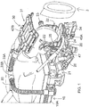
Figure 2 is an isometric view from one side of the head clamp and lower coil portion ofFigure 1 . -
Figure 3 is an isometric view from the front end of the head clamp and lower coil portion ofFigure 1 . -
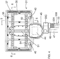
Figure 4 is a top plan view of the RF coil ofFigure 1 with the top foam sheet removed to expose the interior construction. -
Figure 5 is a cross sectional view along the lines 5-5 through the RF coil ofFigure 4 . -
Figure 6 is a cross sectional view along the lines 6-6 through the RF coil ofFigure 4 . - In the drawings like characters of reference indicate corresponding parts in the different figures.
- In
Figure 1 is shown an arrangement for carrying out Magnetic Resonance Imaging of a patient while the patient remains stationary on a patient support table. The arrangement provides a room in which is mounted a patient support table 10 with doors at one side of the room for entry into the room of amagnet 3 of an MR imaging system from a magnet bay. The table 10 described and illustrated herein is used in an arrangement where the patient remains in position on the table during surgery and while imaging is effected intra-operatively or postoperatively using MRI. - The MR is a high-field (e.g. 1.5T or 3T) magnet that moves on overhead rails between the two or more rooms as described above. The arrangement may be used in a typical three room configuration with the Angiography Room (AR) on the left, a Diagnostic Room (DR) in the middle, and an Operating Room on the right. The magnet moves on overhead rails between the rooms and can image in each.
- The Patient Handling System or support table is indicated generally at 10. The patient support table includes a base of a conventional construction which allows the base to move a patient support portion to required locations in height and in orientation. Suitable drive mechanisms and couplings are known in the art and thus are not required to be described herein. At the top of the base is mounted the patient support portion in the form of a generally planar body formed of a fiber reinforced plastics material so as to define a surface area sufficient for supporting the patient while lying on the patient support portion.
- The apparatus includes a
head clamp 20 which is connected onto the end of the table 10 by a mountingbracket 21. The details of these components are well known to a person skilled in this art and can vary so that they are not described herein. It suffice to say that the head clamp includes a C-shaped clamp section and a pair of skullclamp pin members - The C-shaped clamp section includes a
base portion 24 which is adjustable in width with a pair ofupstanding arms 25 each of which carries arespective pin member - The C-shaped clamp section is carried on a
bracket 26 which includes a plurality of interconnected and adjustable arms which allow the C-shaped clamp section to be adjusted in a number of direction so that the plane of the clamp section can be moved side to side, up and down, and can be tilted around axes generally longitudinal of the patient support table and generally transverse to the patient support table. Thus as shown inFigures 2 and3 , theclamp section 24 is tilted forwardly of a vertical plane to move the clamp pin members forwardly. It is also possible that theclamp section 24 can be rotated around an axis longitudinal to the table so that one clamp pin member is higher than the other. - The apparatus further includes an
RF coil 30 formed oftop coil portion 31 and abottom coil portion 32. These are each formed of a plurality of antennae elements so that they cooperate around the head to form a phased array. Thetop coil portion 31 is carried on asupport arm 33 connected to theside rail 10A of the table 10. The bottom coil portion is carried on anadjustable bracket 34 which is rigid but can be adjusted so as to move the connection at the front of the bottom coil relative to the head clamp. - A schematic illustration of the
RF coil 31 is shown inFigure 4 and includes a printedcircuit board 36. The board is formed of polyimide film (Kapton™) which is a flexible substrate onto which the antennae are formed as conductive traces and on which are carried the various circuit components well known to be required in such coil constructions. The circuitry of the coil includes conductive traces 37,capacitors 38,diodes 40, andpre-amplifiers 44. All of these elements are conventional in general construction and are well known to persons skilled in the art of coil design so that detailed explanation is not required here. - The upper and lower coil portions are basically formed in the same construction to provide a flexible arrangement to allow the coil portions to take up a generally U-shaped configuration in which the bottom of the legs of the U-shape of the top coil portion meet or lie closely adjacent the top of the legs of the bottom coil to provide the surrounding arrangement.
- In each case the coil portion is formed of a foam
flexible material 42 allowing the coil to be flexed to different shapes. In particular, as shown in the cross-sections ofFigures 5 and6 , the flexible material comprises twosheets center plane 43 of the coil with the components of the coil on theflexible circuit board 36 located at the center plane. Thus the coil portion is movable by flexing from a flat condition to different curvatures where it is generally channel shaped and is movable by flexing to different curvatures. - The two overlying sheets of foam material are coextensive with the
board 36 spaced inwardly from the side edges. The components of the circuit are also embedded in the foam material. The thickness of the foam material is selected to allow the required degree of flexing. The foam material may be notched at spaced positions across the panel to localize the flexing action at preferred positions with those preferred positions being located mid way across the sections of the antenna so as to minimize bending at regions wherecomponents circuit board 36. - The antennae and their pre-amplifiers connect to a
central unit 44 mounted in ahousing 45 at one edge of the panel. The housing connects to aneck 46 to which theRF cable 47 is attached to pass from the RF coil to the control system at a remote location. - Such flexible RF coil constructions are known. Typically they have some elasticity which prevents their taking up and retaining the required shape closely surrounding the anatomy of the patient.
- In respect of the top coil portion, in order to maintain the required shape of the panel forming the coil portion, there is provided at least one
stiffening element 50 attached to the flexible foam material and movable therewith. Thestiffening elements 50 provide a resistance to bending which is arranged such that the stiffening elements act to hold the flexible material in the different shapes. - The coil 41 includes at least one
longitudinal backbone member 51 connected to thehousing 45 and extending longitudinally along the panel forming the coil construction. This holds the central axis straight so that bending occurs only about lines parallel to this central axis. Thestiffening elements 50 extend at right angles to the backbone member and are fastened to it at spaced positions along the backbone member. The backbone member allows the coil 41 to be held in place by aflexible arm 33 connected to the neck 56. The backbone member and the stiffening elements are embedded in the top sheet of the foam preferably by addingfoam ribs 52 molded into the top sheet of foam. - Thus the stiffening elements extend transversely across the coil and act to hold the coil in the required selected channel shape at the required curvature.
- There are preferably two stiffening members each on a respective side of the backbone member and spaced longitudinally of the backbone member but more than two members can be used.
- The stiffening members could be comprised of a continuous length installed without a central backbone member if the coil is intended to be formed into a continuous radius without a central flat section. The stiffening elements can also be arranged in a 'H' shape that allows some limited curvature in the head-foot direction (superior-inferior)
- The stiffening members comprise a plurality of
separate pieces 54 each connected to the next along the length of the stiffening member and each pivotally movable relative to the next. Such a material is commercially available for forming bendable ducts. A suitable supplier of such material is Lockwood Products Inc (Lake Oswego, OR). It has sufficient resistance to bending as to provide the required holding forces although other materials of a similar nature can be used and particularly a material that has a thinner profile than material available from this supplier. - The
upper coil 31 is carried at one end of theflexible arm 33 for movement of the upper coil to different locations relative to the patient, an opposite end of thearm 33 being carried on a location fixed relative to the patient support table and in this example at theside rail 10A. The flexible arm comprises a single piece which is flexible along its full length so that it can be bent to the required orientation to place the top coil portion at the required location. The intention is that the arm just has sufficient stiffness to hold the coil portion in place with possibly some support coming from minor contact with the anatomy of the patient. The flexible arm is formed of afoam material 33A forming an elongate element of constant cross-section with astiffening element 33B along the length of the arm of the same construction as that described above. The dimensions of the stiffening element may be greater to provide an increased holding force. - In order to mount the
arm 33 to the coil portion, theflexible arm 33 includes at its end aclamp 33C for engagement onto thesleeve 46 of thehousing 45 at one side of the sleeve so that thearm 33 at thehousing 45 is parallel to theRF cable 47. Thearm 33 then extends generally along the chest of the patient before diverging to one side to connect to the side rail. The RF cable extends along the required route to the control system. - The head clamp is thus attached to the patient support table for holding the head of the patient stationary for an invasive procedure. The
lower coil 32 is generally channel shaped when curved into its operating position and is movable by flexing about longitudinal lines to different curvatures. - The lower coil is similar in construction to that shown in
Figure 4 and includes ahousing 45 at one end as previously described. In this arrangement however thesleeve 46A to thecable 47 extends to one side rather than along the centerline. This leaves room for a mountingpin 60 which extends through the housing at the centerline in a direction at right angles to the centerline so as to engage onto an outer end of theadjustable bracket 34 connected to the head clamp. - The bracket 35 is defined by the
pin 60 and a series ofarms swivel couplings pin 60 allows rotational movement about the longitudinal axis of the pin. Thecoupling 66 allows rotational movement about an axis transverse to the head clamp. Thecouplings coil portion 32 can be adjusted in six degrees of freedom. - The adjustable mount is arranged after adjustment to hold the end of the lower coil at a rigidly fixed location. In this way the head clamp can be adjusted to hold the head of the patient at a desired location for the surgical intervention. With the clamp in its required position, the
pin 60 and therefore thecenter line 60A of the coil portion can be adjusted so that thecenter line 60A is as close to parallel to the axis of the magnet bore as possible to provide the best imaging. The remainder of the coil portion is then held in place by the C-shaped mounting 25 which cups and locates the coil portion into its required channel shape. As shown in the figures, this allows the C-shapedbracket 25 to take up different positions inclined to the required angle which is shown for example inclined forwardly but it can also be inclined to one side. The positioning of the forward end of the coil portion locates the coil portion relative to the C-shaped clamp and thus locates the coil portion in the best position and orientation for imaging. - Thus the head clamp includes a C-shaped clamp section into which the head of the patient is placed with the lower coil between the head of the patient and the C-shaped clamp section and the C-shaped clamp section is arranged to engage and hold the lower coil in the required one of the different curvatures to match the space between the head clamp and the head.
- In this way both the upper and lower coil portions are flexible to provide the best position for imaging and are held in place in the best orientation by the top
flexible arm 33 and by the combination of the mounting 34 and the head clamp without the necessity for additional fastening elements.
Claims (9)
- Apparatus for use in Magnetic Resonance imaging of a part of a patient comprising:a patient support table (10);a magnet (3) arranged to generate a magnetic field at the patient support table;an RF coil (30) for use in the MR imaging;the RF coil including an upper coil portion (31) for location on top of the patient and a lower coil portion (32) for location underneath the patient;wherein the upper coil portion (31) is formed of a flexible material (42) allowing the upper coil portion (31) to be flexed to different shapes with at least one stiffening element (50) attached to the flexible material and movable therewith and having a resistance to bending which is arranged such that said at least one stiffening element (50) acts to hold the flexible material in the different shapes;characterized in that said at least one stiffening element (50) comprises a plurality of separate pieces (54) each connected to the next along the length of the stiffening element (50) and each pivotally movable relative to the next.
- The apparatus according to Claim 1 wherein the flexible material (42) comprises a foam and said at least one stiffening element (50) is embedded in the foam.
- The apparatus according to Claim 1 wherein said at least one stiffening element (50) extends transversely across the upper coil portion (31).
- The apparatus according to Claim 1 wherein the upper coil portion (31) includes at least one longitudinal backbone member (51) and said at least one stiffening element (50) extends at right angles to the backbone member.
- The apparatus according to Claim 1 wherein the upper coil portion (31) is carried at one end of a flexible arm (33) for movement of the upper coil portion (31) to different locations relative to the patient, an opposite end of the flexible arm (33) being carried on a location fixed relative to the patient support table (10).
- The apparatus according to Claim 5 wherein the RF coil includes a housing (45) with a sleeve (46) to which is attached an RF cable (47) and wherein the flexible arm (33) includes at said one end a clamp (33C) for engagement onto the sleeve (46) of the housing (45) so that the flexible arm (33) at the housing (45) is parallel to the RF cable (47).
- The apparatus according to Claim 1 wherein there is provided a head clamp (20) attached to the patient support table (10 for holding the head of the patient stationary for an invasive procedure, wherein the lower coil portion (32) is generally channel shaped and is movable by flexing about longitudinal lines to different curvatures, and wherein the lower coil portion (32) is attached at one longitudinal end to an adjustable mount connected to the head clamp (20) and wherein the adjustable mount is adjustable to allow movement of the end of the lower coil portion (32) relative to the head clamp (20).
- The apparatus according to Claim 7 wherein the head clamp (20) includes a C-shaped clamp section (25) configured for placement of the head of the patient into it with the lower coil portion (32) between the head of the patient and the C-shaped clamp section (25) and wherein the C-shaped clamp section (25) is arranged to engage and hold the lower coil portion (32) in one of said different curvatures.
- The apparatus according to Claim 8 wherein the adjustable mount is arranged to engage the lower coil portion (32) on a longitudinal center line of the lower coil portion (32) and wherein the adjustable mount is arranged to allow movement of the center line of the lower coil portion (32) to different angles and positions relative to a plane containing the C-shaped clamp section (25) while the lower coil portion (32) remains in engagement with and held by the C-shaped clamp section (25).
Applications Claiming Priority (1)
| Application Number | Priority Date | Filing Date | Title |
|---|---|---|---|
| US12/770,882 US8604789B2 (en) | 2010-04-30 | 2010-04-30 | RF coil assembly for use in magnetic resonance imaging |
Publications (3)
| Publication Number | Publication Date |
|---|---|
| EP2385385A2 EP2385385A2 (en) | 2011-11-09 |
| EP2385385A3 EP2385385A3 (en) | 2012-01-04 |
| EP2385385B1 true EP2385385B1 (en) | 2020-08-26 |
Family
ID=44315174
Family Applications (1)
| Application Number | Title | Priority Date | Filing Date |
|---|---|---|---|
| EP11164243.5A Active EP2385385B1 (en) | 2010-04-30 | 2011-04-29 | RF coil assembly for use in magnetic resonance imaging |
Country Status (3)
| Country | Link |
|---|---|
| US (1) | US8604789B2 (en) |
| EP (1) | EP2385385B1 (en) |
| JP (1) | JP5839827B2 (en) |
Families Citing this family (19)
| Publication number | Priority date | Publication date | Assignee | Title |
|---|---|---|---|---|
| US8256430B2 (en) | 2001-06-15 | 2012-09-04 | Monteris Medical, Inc. | Hyperthermia treatment and probe therefor |
| US8979871B2 (en) | 2009-08-13 | 2015-03-17 | Monteris Medical Corporation | Image-guided therapy of a tissue |
| US8604789B2 (en) * | 2010-04-30 | 2013-12-10 | Imris Inc. | RF coil assembly for use in magnetic resonance imaging |
| WO2012137179A1 (en) * | 2011-04-08 | 2012-10-11 | Monteris Medical, Inc. | Head fixation system and method |
| GB2551302B (en) | 2013-01-08 | 2018-02-28 | Pulseteq Ltd | Radiofrequency coils |
| US10675113B2 (en) | 2014-03-18 | 2020-06-09 | Monteris Medical Corporation | Automated therapy of a three-dimensional tissue region |
| US20150265353A1 (en) | 2014-03-18 | 2015-09-24 | Monteris Medical Corporation | Image-guided therapy of a tissue |
| US9433383B2 (en) | 2014-03-18 | 2016-09-06 | Monteris Medical Corporation | Image-guided therapy of a tissue |
| EP3194997B1 (en) * | 2014-09-01 | 2023-10-11 | Koninklijke Philips N.V. | Magnetic resonance imaging receive coil with reduced radiation attenuation |
| US10327830B2 (en) | 2015-04-01 | 2019-06-25 | Monteris Medical Corporation | Cryotherapy, thermal therapy, temperature modulation therapy, and probe apparatus therefor |
| US10488475B2 (en) | 2015-04-02 | 2019-11-26 | Imris, Inc. | Transceiver coil array facilitating MR-guided procedures |
| DE102015216409A1 (en) * | 2015-08-27 | 2017-03-02 | Siemens Healthcare Gmbh | Medical imaging device with a housing unit |
| EP3721245A4 (en) | 2018-04-23 | 2021-08-04 | Mr Instruments, Inc. | PORTABLE, OPEN AND ADJUSTABLE MRI HEAD COIL |
| TW202015621A (en) | 2018-07-19 | 2020-05-01 | 美商超精細研究股份有限公司 | Method and equipment for positioning patients in magnetic resonance imaging |
| US20200246106A1 (en) * | 2019-01-31 | 2020-08-06 | Sino Canada Health Engineering Research Institute (Hefei) Ltd. | Imaging Method for Use in Surgical Procedures |
| CN111505549A (en) * | 2019-01-31 | 2020-08-07 | 中加健康工程研究院(合肥)有限公司 | A mobile MRI system |
| WO2021108773A1 (en) | 2019-11-26 | 2021-06-03 | Rhieneck Thomas J | Conformable mri receiver coil system capable of supporting ultrasound, diagnostic, therapeutic, and interventional implements |
| CN114114110A (en) * | 2021-12-23 | 2022-03-01 | 苏州众志医疗科技有限公司 | Magnetic resonance coil device for imaging temporomandibular joint and cochlear |
| US12405328B2 (en) * | 2023-01-09 | 2025-09-02 | GE Precision Healthcare LLC | Full body posterior coil for a magnetic resonance imaging system |
Family Cites Families (15)
| Publication number | Priority date | Publication date | Assignee | Title |
|---|---|---|---|---|
| JP2592880B2 (en) * | 1988-01-21 | 1997-03-19 | 株式会社東芝 | Magnetic resonance imaging equipment |
| JPH04279149A (en) * | 1991-03-07 | 1992-10-05 | Toshiba Corp | Probe for magnetic resonance imaging apparatus |
| US5449206A (en) | 1994-01-04 | 1995-09-12 | Lockwood Products, Inc. | Ball and socket joint with internal stop |
| US5594339A (en) * | 1995-07-11 | 1997-01-14 | Picker International, Inc. | Flexible nuclear magnetic resonance receiver coils and systems |
| US6577888B1 (en) * | 2000-09-29 | 2003-06-10 | Usa Instruments, Inc. | Sliding-dome and split-top MRI radio frequency quadrature array coil system |
| US6650926B1 (en) | 2001-03-30 | 2003-11-18 | Usa Instruments, Inc. | Flexible multi-section MRI radio frequency array coil |
| US7049819B2 (en) | 2003-01-21 | 2006-05-23 | General Electric Company | Diagonal-arranged quadrature MRI radio frequency array coil system for three dimensional parallel imaging |
| DE10324870B4 (en) * | 2003-06-02 | 2012-09-27 | Siemens Ag | Magnetic resonance system with a local coil arranged in an examination tunnel |
| DE102004005120B4 (en) | 2004-02-02 | 2008-01-17 | Siemens Ag | Local coil unit for use in a magnetic resonance apparatus |
| US7382132B1 (en) * | 2005-04-29 | 2008-06-03 | General Electric Company | 6-channel array coil for magnetic resonance imaging |
| US7467004B2 (en) * | 2005-05-12 | 2008-12-16 | General Electric Company | System, method and apparatus for surgical patient table |
| JP4854448B2 (en) * | 2006-09-28 | 2012-01-18 | 株式会社東芝 | MRI apparatus and RF coil unit for MRI apparatus |
| US7365542B1 (en) * | 2006-10-31 | 2008-04-29 | General Electric Company | Flexible RF coil assembly and method of making same |
| DE102007031345B4 (en) | 2007-07-05 | 2018-09-13 | Siemens Healthcare Gmbh | Arrangement and carrier device for fixing local coils in a magnetic resonance apparatus |
| US8604789B2 (en) * | 2010-04-30 | 2013-12-10 | Imris Inc. | RF coil assembly for use in magnetic resonance imaging |
-
2010
- 2010-04-30 US US12/770,882 patent/US8604789B2/en active Active
-
2011
- 2011-04-22 JP JP2011096550A patent/JP5839827B2/en active Active
- 2011-04-29 EP EP11164243.5A patent/EP2385385B1/en active Active
Non-Patent Citations (1)
| Title |
|---|
| None * |
Also Published As
| Publication number | Publication date |
|---|---|
| US8604789B2 (en) | 2013-12-10 |
| JP5839827B2 (en) | 2016-01-06 |
| JP2011235094A (en) | 2011-11-24 |
| US20110267059A1 (en) | 2011-11-03 |
| EP2385385A3 (en) | 2012-01-04 |
| EP2385385A2 (en) | 2011-11-09 |
Similar Documents
| Publication | Publication Date | Title |
|---|---|---|
| US8604789B2 (en) | RF coil assembly for use in magnetic resonance imaging | |
| JP7481028B2 (en) | Multi-Modality Medical Procedure Mattress-Based Device | |
| US20230380690A1 (en) | Wearable open and adjustable mri head coil | |
| US12005004B2 (en) | Headset system | |
| US20160106508A1 (en) | Structure for supporting a medical device on a patient during surgical procedures | |
| US5680861A (en) | Modular subject positioning system for medical imaging | |
| US10165961B2 (en) | Adjustable head coil systems and methods for magnetic resonance imaging | |
| US8513946B2 (en) | Movable table for magnetic resonance imaging | |
| US20070129634A1 (en) | Biomedical positioning and stabilization system | |
| US20140323851A1 (en) | Subject placement and head positioning device | |
| US9095489B2 (en) | Surgical head support adapter | |
| CN109998675A (en) | The slim double pad Magnetic oriented systems of autotracking formula | |
| WO2013001377A2 (en) | Supine breast mri | |
| EP3932320B1 (en) | Apparatus for shielding radiation | |
| EP4065995B1 (en) | Conformable mri receiver coil system capable of supporting ultrasound, diagnostic, therapeutic, and interventional implements | |
| CN103284721B (en) | Patient-supporting device and the medical imaging devices with patient-supporting device | |
| EP3801433B1 (en) | Arm support apparatus | |
| EP3866695B1 (en) | Patient support mechanism for a portable medical scanner | |
| CN210933360U (en) | Stomach is pipe fixing device for surgery | |
| US20240298978A1 (en) | Anatomic positioning device | |
| CN223640732U (en) | Device capable of adjusting head, neck and shoulder heights | |
| CN213963833U (en) | Orthopedics fixing device |
Legal Events
| Date | Code | Title | Description |
|---|---|---|---|
| AK | Designated contracting states |
Kind code of ref document: A2 Designated state(s): AL AT BE BG CH CY CZ DE DK EE ES FI FR GB GR HR HU IE IS IT LI LT LU LV MC MK MT NL NO PL PT RO RS SE SI SK SM TR |
|
| AX | Request for extension of the european patent |
Extension state: BA ME |
|
| PUAI | Public reference made under article 153(3) epc to a published international application that has entered the european phase |
Free format text: ORIGINAL CODE: 0009012 |
|
| PUAL | Search report despatched |
Free format text: ORIGINAL CODE: 0009013 |
|
| AK | Designated contracting states |
Kind code of ref document: A3 Designated state(s): AL AT BE BG CH CY CZ DE DK EE ES FI FR GB GR HR HU IE IS IT LI LT LU LV MC MK MT NL NO PL PT RO RS SE SI SK SM TR |
|
| AX | Request for extension of the european patent |
Extension state: BA ME |
|
| RIC1 | Information provided on ipc code assigned before grant |
Ipc: G01R 33/34 20060101AFI20111128BHEP |
|
| 17P | Request for examination filed |
Effective date: 20120704 |
|
| STAA | Information on the status of an ep patent application or granted ep patent |
Free format text: STATUS: EXAMINATION IS IN PROGRESS |
|
| 17Q | First examination report despatched |
Effective date: 20190506 |
|
| RAP1 | Party data changed (applicant data changed or rights of an application transferred) |
Owner name: IMRIS INC. |
|
| GRAP | Despatch of communication of intention to grant a patent |
Free format text: ORIGINAL CODE: EPIDOSNIGR1 |
|
| STAA | Information on the status of an ep patent application or granted ep patent |
Free format text: STATUS: GRANT OF PATENT IS INTENDED |
|
| RIC1 | Information provided on ipc code assigned before grant |
Ipc: G01R 33/3415 20060101ALI20191112BHEP Ipc: G01R 33/34 20060101AFI20191112BHEP |
|
| INTG | Intention to grant announced |
Effective date: 20191129 |
|
| GRAS | Grant fee paid |
Free format text: ORIGINAL CODE: EPIDOSNIGR3 |
|
| GRAA | (expected) grant |
Free format text: ORIGINAL CODE: 0009210 |
|
| STAA | Information on the status of an ep patent application or granted ep patent |
Free format text: STATUS: THE PATENT HAS BEEN GRANTED |
|
| AK | Designated contracting states |
Kind code of ref document: B1 Designated state(s): AL AT BE BG CH CY CZ DE DK EE ES FI FR GB GR HR HU IE IS IT LI LT LU LV MC MK MT NL NO PL PT RO RS SE SI SK SM TR |
|
| REG | Reference to a national code |
Ref country code: GB Ref legal event code: FG4D |
|
| REG | Reference to a national code |
Ref country code: CH Ref legal event code: EP |
|
| REG | Reference to a national code |
Ref country code: DE Ref legal event code: R096 Ref document number: 602011068332 Country of ref document: DE |
|
| REG | Reference to a national code |
Ref country code: AT Ref legal event code: REF Ref document number: 1306874 Country of ref document: AT Kind code of ref document: T Effective date: 20200915 Ref country code: CH Ref legal event code: NV Representative=s name: DENNEMEYER AG, CH |
|
| REG | Reference to a national code |
Ref country code: IE Ref legal event code: FG4D |
|
| REG | Reference to a national code |
Ref country code: NL Ref legal event code: FP |
|
| REG | Reference to a national code |
Ref country code: SE Ref legal event code: TRGR |
|
| REG | Reference to a national code |
Ref country code: LT Ref legal event code: MG4D |
|
| PG25 | Lapsed in a contracting state [announced via postgrant information from national office to epo] |
Ref country code: BG Free format text: LAPSE BECAUSE OF FAILURE TO SUBMIT A TRANSLATION OF THE DESCRIPTION OR TO PAY THE FEE WITHIN THE PRESCRIBED TIME-LIMIT Effective date: 20201126 Ref country code: PT Free format text: LAPSE BECAUSE OF FAILURE TO SUBMIT A TRANSLATION OF THE DESCRIPTION OR TO PAY THE FEE WITHIN THE PRESCRIBED TIME-LIMIT Effective date: 20201228 Ref country code: GR Free format text: LAPSE BECAUSE OF FAILURE TO SUBMIT A TRANSLATION OF THE DESCRIPTION OR TO PAY THE FEE WITHIN THE PRESCRIBED TIME-LIMIT Effective date: 20201127 Ref country code: NO Free format text: LAPSE BECAUSE OF FAILURE TO SUBMIT A TRANSLATION OF THE DESCRIPTION OR TO PAY THE FEE WITHIN THE PRESCRIBED TIME-LIMIT Effective date: 20201126 Ref country code: LT Free format text: LAPSE BECAUSE OF FAILURE TO SUBMIT A TRANSLATION OF THE DESCRIPTION OR TO PAY THE FEE WITHIN THE PRESCRIBED TIME-LIMIT Effective date: 20200826 Ref country code: FI Free format text: LAPSE BECAUSE OF FAILURE TO SUBMIT A TRANSLATION OF THE DESCRIPTION OR TO PAY THE FEE WITHIN THE PRESCRIBED TIME-LIMIT Effective date: 20200826 Ref country code: HR Free format text: LAPSE BECAUSE OF FAILURE TO SUBMIT A TRANSLATION OF THE DESCRIPTION OR TO PAY THE FEE WITHIN THE PRESCRIBED TIME-LIMIT Effective date: 20200826 |
|
| REG | Reference to a national code |
Ref country code: AT Ref legal event code: MK05 Ref document number: 1306874 Country of ref document: AT Kind code of ref document: T Effective date: 20200826 |
|
| PG25 | Lapsed in a contracting state [announced via postgrant information from national office to epo] |
Ref country code: LV Free format text: LAPSE BECAUSE OF FAILURE TO SUBMIT A TRANSLATION OF THE DESCRIPTION OR TO PAY THE FEE WITHIN THE PRESCRIBED TIME-LIMIT Effective date: 20200826 Ref country code: RS Free format text: LAPSE BECAUSE OF FAILURE TO SUBMIT A TRANSLATION OF THE DESCRIPTION OR TO PAY THE FEE WITHIN THE PRESCRIBED TIME-LIMIT Effective date: 20200826 Ref country code: PL Free format text: LAPSE BECAUSE OF FAILURE TO SUBMIT A TRANSLATION OF THE DESCRIPTION OR TO PAY THE FEE WITHIN THE PRESCRIBED TIME-LIMIT Effective date: 20200826 Ref country code: IS Free format text: LAPSE BECAUSE OF FAILURE TO SUBMIT A TRANSLATION OF THE DESCRIPTION OR TO PAY THE FEE WITHIN THE PRESCRIBED TIME-LIMIT Effective date: 20201226 |
|
| PG25 | Lapsed in a contracting state [announced via postgrant information from national office to epo] |
Ref country code: RO Free format text: LAPSE BECAUSE OF FAILURE TO SUBMIT A TRANSLATION OF THE DESCRIPTION OR TO PAY THE FEE WITHIN THE PRESCRIBED TIME-LIMIT Effective date: 20200826 Ref country code: SM Free format text: LAPSE BECAUSE OF FAILURE TO SUBMIT A TRANSLATION OF THE DESCRIPTION OR TO PAY THE FEE WITHIN THE PRESCRIBED TIME-LIMIT Effective date: 20200826 Ref country code: EE Free format text: LAPSE BECAUSE OF FAILURE TO SUBMIT A TRANSLATION OF THE DESCRIPTION OR TO PAY THE FEE WITHIN THE PRESCRIBED TIME-LIMIT Effective date: 20200826 Ref country code: DK Free format text: LAPSE BECAUSE OF FAILURE TO SUBMIT A TRANSLATION OF THE DESCRIPTION OR TO PAY THE FEE WITHIN THE PRESCRIBED TIME-LIMIT Effective date: 20200826 Ref country code: CZ Free format text: LAPSE BECAUSE OF FAILURE TO SUBMIT A TRANSLATION OF THE DESCRIPTION OR TO PAY THE FEE WITHIN THE PRESCRIBED TIME-LIMIT Effective date: 20200826 |
|
| REG | Reference to a national code |
Ref country code: DE Ref legal event code: R097 Ref document number: 602011068332 Country of ref document: DE |
|
| PG25 | Lapsed in a contracting state [announced via postgrant information from national office to epo] |
Ref country code: AT Free format text: LAPSE BECAUSE OF FAILURE TO SUBMIT A TRANSLATION OF THE DESCRIPTION OR TO PAY THE FEE WITHIN THE PRESCRIBED TIME-LIMIT Effective date: 20200826 Ref country code: AL Free format text: LAPSE BECAUSE OF FAILURE TO SUBMIT A TRANSLATION OF THE DESCRIPTION OR TO PAY THE FEE WITHIN THE PRESCRIBED TIME-LIMIT Effective date: 20200826 Ref country code: ES Free format text: LAPSE BECAUSE OF FAILURE TO SUBMIT A TRANSLATION OF THE DESCRIPTION OR TO PAY THE FEE WITHIN THE PRESCRIBED TIME-LIMIT Effective date: 20200826 |
|
| PG25 | Lapsed in a contracting state [announced via postgrant information from national office to epo] |
Ref country code: SK Free format text: LAPSE BECAUSE OF FAILURE TO SUBMIT A TRANSLATION OF THE DESCRIPTION OR TO PAY THE FEE WITHIN THE PRESCRIBED TIME-LIMIT Effective date: 20200826 |
|
| PLBE | No opposition filed within time limit |
Free format text: ORIGINAL CODE: 0009261 |
|
| STAA | Information on the status of an ep patent application or granted ep patent |
Free format text: STATUS: NO OPPOSITION FILED WITHIN TIME LIMIT |
|
| PG25 | Lapsed in a contracting state [announced via postgrant information from national office to epo] |
Ref country code: IT Free format text: LAPSE BECAUSE OF FAILURE TO SUBMIT A TRANSLATION OF THE DESCRIPTION OR TO PAY THE FEE WITHIN THE PRESCRIBED TIME-LIMIT Effective date: 20200826 |
|
| 26N | No opposition filed |
Effective date: 20210527 |
|
| PG25 | Lapsed in a contracting state [announced via postgrant information from national office to epo] |
Ref country code: SI Free format text: LAPSE BECAUSE OF FAILURE TO SUBMIT A TRANSLATION OF THE DESCRIPTION OR TO PAY THE FEE WITHIN THE PRESCRIBED TIME-LIMIT Effective date: 20200826 |
|
| PG25 | Lapsed in a contracting state [announced via postgrant information from national office to epo] |
Ref country code: MC Free format text: LAPSE BECAUSE OF FAILURE TO SUBMIT A TRANSLATION OF THE DESCRIPTION OR TO PAY THE FEE WITHIN THE PRESCRIBED TIME-LIMIT Effective date: 20200826 |
|
| PG25 | Lapsed in a contracting state [announced via postgrant information from national office to epo] |
Ref country code: LU Free format text: LAPSE BECAUSE OF NON-PAYMENT OF DUE FEES Effective date: 20210429 |
|
| REG | Reference to a national code |
Ref country code: BE Ref legal event code: MM Effective date: 20210430 |
|
| PG25 | Lapsed in a contracting state [announced via postgrant information from national office to epo] |
Ref country code: IE Free format text: LAPSE BECAUSE OF NON-PAYMENT OF DUE FEES Effective date: 20210429 |
|
| PG25 | Lapsed in a contracting state [announced via postgrant information from national office to epo] |
Ref country code: IS Free format text: LAPSE BECAUSE OF FAILURE TO SUBMIT A TRANSLATION OF THE DESCRIPTION OR TO PAY THE FEE WITHIN THE PRESCRIBED TIME-LIMIT Effective date: 20201226 |
|
| PG25 | Lapsed in a contracting state [announced via postgrant information from national office to epo] |
Ref country code: BE Free format text: LAPSE BECAUSE OF NON-PAYMENT OF DUE FEES Effective date: 20210430 |
|
| PG25 | Lapsed in a contracting state [announced via postgrant information from national office to epo] |
Ref country code: HU Free format text: LAPSE BECAUSE OF FAILURE TO SUBMIT A TRANSLATION OF THE DESCRIPTION OR TO PAY THE FEE WITHIN THE PRESCRIBED TIME-LIMIT; INVALID AB INITIO Effective date: 20110429 Ref country code: CY Free format text: LAPSE BECAUSE OF FAILURE TO SUBMIT A TRANSLATION OF THE DESCRIPTION OR TO PAY THE FEE WITHIN THE PRESCRIBED TIME-LIMIT Effective date: 20200826 |
|
| PG25 | Lapsed in a contracting state [announced via postgrant information from national office to epo] |
Ref country code: MK Free format text: LAPSE BECAUSE OF FAILURE TO SUBMIT A TRANSLATION OF THE DESCRIPTION OR TO PAY THE FEE WITHIN THE PRESCRIBED TIME-LIMIT Effective date: 20200826 |
|
| PG25 | Lapsed in a contracting state [announced via postgrant information from national office to epo] |
Ref country code: TR Free format text: LAPSE BECAUSE OF FAILURE TO SUBMIT A TRANSLATION OF THE DESCRIPTION OR TO PAY THE FEE WITHIN THE PRESCRIBED TIME-LIMIT Effective date: 20200826 |
|
| PG25 | Lapsed in a contracting state [announced via postgrant information from national office to epo] |
Ref country code: MT Free format text: LAPSE BECAUSE OF FAILURE TO SUBMIT A TRANSLATION OF THE DESCRIPTION OR TO PAY THE FEE WITHIN THE PRESCRIBED TIME-LIMIT Effective date: 20200826 |
|
| PGFP | Annual fee paid to national office [announced via postgrant information from national office to epo] |
Ref country code: NL Payment date: 20250429 Year of fee payment: 15 |
|
| PGFP | Annual fee paid to national office [announced via postgrant information from national office to epo] |
Ref country code: DE Payment date: 20250429 Year of fee payment: 15 |
|
| PGFP | Annual fee paid to national office [announced via postgrant information from national office to epo] |
Ref country code: GB Payment date: 20250429 Year of fee payment: 15 |
|
| PGFP | Annual fee paid to national office [announced via postgrant information from national office to epo] |
Ref country code: FR Payment date: 20250429 Year of fee payment: 15 |
|
| PGFP | Annual fee paid to national office [announced via postgrant information from national office to epo] |
Ref country code: CH Payment date: 20250508 Year of fee payment: 15 |
|
| PGFP | Annual fee paid to national office [announced via postgrant information from national office to epo] |
Ref country code: SE Payment date: 20250429 Year of fee payment: 15 |
|
| REG | Reference to a national code |
Ref country code: CH Ref legal event code: U11 Free format text: ST27 STATUS EVENT CODE: U-0-0-U10-U11 (AS PROVIDED BY THE NATIONAL OFFICE) Effective date: 20260501 |