EP2385242A2 - Isolator for fuel injector - Google Patents
Isolator for fuel injector Download PDFInfo
- Publication number
- EP2385242A2 EP2385242A2 EP11164536A EP11164536A EP2385242A2 EP 2385242 A2 EP2385242 A2 EP 2385242A2 EP 11164536 A EP11164536 A EP 11164536A EP 11164536 A EP11164536 A EP 11164536A EP 2385242 A2 EP2385242 A2 EP 2385242A2
- Authority
- EP
- European Patent Office
- Prior art keywords
- fuel injector
- engine component
- isolation
- stepped bore
- support member
- Prior art date
- Legal status (The legal status is an assumption and is not a legal conclusion. Google has not performed a legal analysis and makes no representation as to the accuracy of the status listed.)
- Withdrawn
Links
- 239000000446 fuel Substances 0.000 title claims abstract description 205
- 238000002955 isolation Methods 0.000 claims abstract description 173
- 238000002485 combustion reaction Methods 0.000 claims description 21
- 230000006835 compression Effects 0.000 claims description 13
- 238000007906 compression Methods 0.000 claims description 13
- 238000002347 injection Methods 0.000 description 21
- 239000007924 injection Substances 0.000 description 21
- 239000000463 material Substances 0.000 description 8
- 239000002184 metal Substances 0.000 description 5
- 230000004323 axial length Effects 0.000 description 4
- 239000007921 spray Substances 0.000 description 3
- 230000002411 adverse Effects 0.000 description 2
- 230000000694 effects Effects 0.000 description 2
- 238000000034 method Methods 0.000 description 2
- 239000004033 plastic Substances 0.000 description 2
- 230000001627 detrimental effect Effects 0.000 description 1
- NBVXSUQYWXRMNV-UHFFFAOYSA-N fluoromethane Chemical compound FC NBVXSUQYWXRMNV-UHFFFAOYSA-N 0.000 description 1
- 239000002828 fuel tank Substances 0.000 description 1
- 238000009434 installation Methods 0.000 description 1
- 230000003993 interaction Effects 0.000 description 1
- 230000002093 peripheral effect Effects 0.000 description 1
- 239000012858 resilient material Substances 0.000 description 1
- 230000000717 retained effect Effects 0.000 description 1
- 125000006850 spacer group Chemical group 0.000 description 1
Images


Classifications
-
- F—MECHANICAL ENGINEERING; LIGHTING; HEATING; WEAPONS; BLASTING
- F02—COMBUSTION ENGINES; HOT-GAS OR COMBUSTION-PRODUCT ENGINE PLANTS
- F02M—SUPPLYING COMBUSTION ENGINES IN GENERAL WITH COMBUSTIBLE MIXTURES OR CONSTITUENTS THEREOF
- F02M61/00—Fuel-injectors not provided for in groups F02M39/00 - F02M57/00 or F02M67/00
- F02M61/14—Arrangements of injectors with respect to engines; Mounting of injectors
-
- F—MECHANICAL ENGINEERING; LIGHTING; HEATING; WEAPONS; BLASTING
- F02—COMBUSTION ENGINES; HOT-GAS OR COMBUSTION-PRODUCT ENGINE PLANTS
- F02M—SUPPLYING COMBUSTION ENGINES IN GENERAL WITH COMBUSTIBLE MIXTURES OR CONSTITUENTS THEREOF
- F02M53/00—Fuel-injection apparatus characterised by having heating, cooling or thermally-insulating means
- F02M53/04—Injectors with heating, cooling, or thermally-insulating means
- F02M53/046—Injectors with heating, cooling, or thermally-insulating means with thermally-insulating means
-
- F—MECHANICAL ENGINEERING; LIGHTING; HEATING; WEAPONS; BLASTING
- F02—COMBUSTION ENGINES; HOT-GAS OR COMBUSTION-PRODUCT ENGINE PLANTS
- F02M—SUPPLYING COMBUSTION ENGINES IN GENERAL WITH COMBUSTIBLE MIXTURES OR CONSTITUENTS THEREOF
- F02M2200/00—Details of fuel-injection apparatus, not otherwise provided for
- F02M2200/03—Fuel-injection apparatus having means for reducing or avoiding stress, e.g. the stress caused by mechanical force, by fluid pressure or by temperature variations
-
- F—MECHANICAL ENGINEERING; LIGHTING; HEATING; WEAPONS; BLASTING
- F02—COMBUSTION ENGINES; HOT-GAS OR COMBUSTION-PRODUCT ENGINE PLANTS
- F02M—SUPPLYING COMBUSTION ENGINES IN GENERAL WITH COMBUSTIBLE MIXTURES OR CONSTITUENTS THEREOF
- F02M2200/00—Details of fuel-injection apparatus, not otherwise provided for
- F02M2200/09—Fuel-injection apparatus having means for reducing noise
-
- F—MECHANICAL ENGINEERING; LIGHTING; HEATING; WEAPONS; BLASTING
- F02—COMBUSTION ENGINES; HOT-GAS OR COMBUSTION-PRODUCT ENGINE PLANTS
- F02M—SUPPLYING COMBUSTION ENGINES IN GENERAL WITH COMBUSTIBLE MIXTURES OR CONSTITUENTS THEREOF
- F02M2200/00—Details of fuel-injection apparatus, not otherwise provided for
- F02M2200/85—Mounting of fuel injection apparatus
- F02M2200/858—Mounting of fuel injection apparatus sealing arrangements between injector and engine
Definitions
- the present invention relates to fuel injection systems of internal combustion engines; more particularly, to fuel injectors for direct injection; and most particularly to a device for acoustic and thermal isolation of a fuel injector from a cylinder head.
- Fuel injector systems that deliver fuel to the combustion chamber of an internal combustion engine have been known for many years.
- the typical fuel injection system draws fuel from a fuel tank to a fuel rail mounted adjacent to the cylinder bank of the engine.
- the fuel injectors are electro-mechanical devices that deliver fuel in precise amounts and times to the respective cylinder.
- each fuel injector While the engine is running, the valve within each fuel injector is constantly being operationally cycled from an opened to a closed position. Vibration is generated by the mechanical movement of the injector valves and pressure waves are generated by the movement of the fuel flowing through the injectors. Additionally, a substantial amount of heat generated in the combustion chambers of the cylinder heads may be transferred from the engine to the fuel injector.
- atomized fuel is sprayed by the injector directly into the combustion chamber of the engine.
- the fuel injector tip portion of the direct injection fuel injector typically fits through a stepped bore defined in the cylinder head that has a peripheral bottom shoulder whose top surface provides a positive stop to the bottom surface of the body of the direct injection fuel injector.
- direct metal-to-metal contact between the bottom surface of the direct injection fuel injector body and the top surface of the shoulder allows for unmitigated transfer of the vibration from the direct injection fuel injector to the cylinder head and allows for the transfer of heat by thermal conduction from the cylinder head to the direct injection fuel injector. Noise created thereby can be particularly objectionable at engine idling and low load operation.
- allowing the vibration from the direct injection fuel injector to propagate into the combustion chamber can adversely effect the placement of the highly precise fuel spray pattern into the combustion chamber.
- allowing thermal conduction of heat from the cylinder head to the direct injection fuel injector can lead to injector tip plugging thereby affecting fuel metering and injector spray pattern.
- Prior attempts to isolate vibration and heat transfer between the direct injection fuel injector and the cylinder head have included, for example, the installation of a full-fitting isolation spacer between the bottom surface of the body of the direct injection fuel injector and the shoulder in the cylinder head bore such as a plastic ring on top of a metal ring or a rubber encapsulated metal ring.
- a full-fitting isolation spacer between the bottom surface of the body of the direct injection fuel injector and the shoulder in the cylinder head bore such as a plastic ring on top of a metal ring or a rubber encapsulated metal ring.
- compliant materials may also result in excessive axial movement between the direct injection fuel injector and the cylinder head which can adversely effect the placement of the highly precise fuel spray pattern into the combustion chamber thereby causing combustion problems. Excessive axial movement between the direct injection fuel injector and the cylinder head can also cause detrimental wear to the seal member between the direct injection fuel injector and the cylinder head which seals the combustion chamber from the atmosphere.
- a fuel injector-engine component assembly for an internal combustion engine, the fuel injector-engine component assembly comprising an engine component with a stepped bore defined along an axis, the stepped bore having a stepped bore stop surface facing axially upward, a fuel injector in the stepped bore and extending along said axis, the fuel injector having a fuel injector stop surface facing axially downwardly and axially opposed to the stepped bore stop surface to define a predetermined annular space, the fuel injector being subject in operation to axial pulses that tend to drive the fuel injector stop surface and the stepped bore stop surface together, and an isolation ring disposed in said predetermined annular space and axially between the stepped bore stop surface and the fuel injector stop surface for axially isolating the fuel injector from the engine component, the isolation ring comprising a rigid support member for limiting the axial motion of the stepped bore stop surface and the fuel injector stop surface together to a predetermined, limited degree, and
- the support member limits axial compression of said isolation member at or above the predetermined pressure of said fuel injector.
- the support member includes a recess extending axially thereinto for receiving a portion of the isolation member therewithin.
- a portion of the isolation member extends axially away from the support member below the predetermined pressure of said fuel injector.
- the isolation member expands radially in response to axial compression thereof.
- an expansion cavity is formed between the isolation member and the support member to allow radial expansion of said isolation member in response to axial compression thereof.
- the isolation member includes a plurality of protrusions extending radially inward therefrom that form an interference fit with the fuel injector to retain the isolation ring to the fuel injector prior to the fuel injector being received within the stepped bore of the engine component.
- the support member includes a plurality of fingers that extend radially inward therefrom that form an interference fit with the fuel injector to retain the isolation ring to the fuel injector prior to the fuel injector being received within the stepped bore of the engine component.
- one of the isolation member and support member is in contact with the fuel injector and the other of the isolation member and the support member may be in contact with the engine component below the predetermined pressure of the fuel injector.
- the support member is in contact with both the fuel injector and the engine component at or above the predetermined pressure of the fuel injector.
- the isolation member is in contact with the fuel injector and the engine component below the predetermined pressure of said fuel injector.
- the support member is in contact with the fuel injector and the engine component at or above the predetermined pressure of the fuel injector.
- the support member is a first support member and wherein the isolation ring includes a second rigid support member for limiting the axial motion of the stepped bore stop surface and the fuel injector stop surface together to a predetermined, limited degree.
- a fuel injector extending along an axis for assembly into a stepped bore of an internal combustion engine, the stepped bore having a stepped bore stop surface facing axially upward, the fuel injector comprising a fuel injector stop surface facing axially downwardly and axially opposed to the stepped bore stop surface to define a predetermined annular space upon assembly of the fuel injector into the stepped bore, the fuel injector being subject in operation to axial pulses that tend to drive the fuel injector stop surface and the stepped bore stop surface together; an isolation ring that upon assembly of the fuel injector into the stepped bore is disposed in the predetermined annular space and axially between the stepped bore stop surface and the fuel injector stop surface for axially isolating the fuel injector from the stepped bore, the isolation ring comprising a rigid support member for limiting the axial motion of the stepped bore stop surface and the fuel injector stop surface together to a predetermined, limited, degree and a resilient and compliant isolation
- the support member limits axial compression of said isolation member at or above the predetermined pressure of said fuel injector.
- the support member includes a recess extending axially thereinto for receiving a portion of said isolation member therewithin.
- a portion of the isolation member extends axially away from the support member.
- the isolation member expands radially in response to axial compression thereof.
- an expansion cavity is formed between the isolation member and the support member to allow radial expansion of the isolation member in response to axial compression thereof.
- the isolation member includes a plurality of protrusions extending radially inward therefrom that form an interference fit with the fuel injector to retain the isolation ring to the fuel injector prior to assembly of the fuel injector into the stepped bore.
- the support member includes a plurality of fingers that extend radially inward therefrom that form an interference fit with the fuel injector to retain the isolation ring to the fuel injector prior to assembly of the fuel injector into the stepped bore.
- one of the isolation member and the support member is in contact with said fuel injector and the other of the isolation member and the support member is in contact with the stepped bore below the predetermined pressure of the fuel injector.
- the support member is in contact with both the fuel injector and the stepped bore at or above the predetermined pressure of the fuel injector.
- the said isolation member is in contact with both the fuel injector and the stepped bore below the predetermined pressure of the fuel injector.
- the support member is in contact with both the fuel injector and the stepped bore at or above the predetermined pressure of the fuel injector.
- the support member is a first support member and wherein the isolation ring includes a second rigid support member for limiting the axial motion of the stepped bore stop surface and the fuel injector stop surface together to a predetermined, limited degree.
- a fuel-injector-engine component assembly illustrated as fuel injector-cylinder head assembly 20 of internal combustion engine 22 includes fuel injector 24, an engine component illustrated as cylinder head 26, and isolation ring 28 assembled therebetween. Fuel injector-cylinder head assembly 20 extends along an axis 30.
- Fuel injector 24 extends along axis 30 and includes solenoid housing 32 and injector tip 34 axially extending from solenoid housing 32.
- Solenoid housing 32 includes fuel injector stop surface 35 facing axially downwardly.
- Cylinder head 26 includes stepped bore 36 defined along axis 30 and having stepped bore stop surface 37 facing axially upwardly and center opening 38.
- Fuel injector 24 is assembled in stepped bore 36 of cylinder head 26 such that stepped bore 36 of cylinder head 26 accommodates solenoid housing 32 of fuel injector 24 and such that injector tip 34 extends through center opening 38 of cylinder head 26.
- fuel injector stop surface 35 and stepped bore stop surface 37 axially oppose each other and define predetermined annular space 39.
- Fuel injector 24 is subject to high frequency vibrations or axial pulses that tend to drive fuel injector stop surface 35 and stepped bore stop surface 37 axially together.
- Fuel injector 24 may be, but is not limited to, a fuel injector for direct injection as shown in Fig. 1 .
- Isolation ring 28 is positioned within stepped bore 36 such that isolation ring 28 is positioned adjacent to solenoid housing 32 and encircling fuel injector 24 within predetermined annular space 39. Accordingly, isolation ring 28 has outer circumference 40 that fits into stepped bore 36 and that is wider than center opening 38. Isolation ring 28 further includes center aperture 42 adapted to receive fuel injector 24 therethrough. Isolation ring 28 includes rigid support member 44 and isolation member 46. Support member 44 may be made of any material that is capable of withstanding the axial loads provided by fuel injector 24 while in operation and is preferably made of metal. Isolation member 46 is a compliant, resilient material and may be a rubber material such as fluorocarbon. Although not shown, it should now be understood that support member 44 may be formed integrally with fuel injector 24 or formed separately and attached to fuel injector 24.
- Support member 44 includes recess 48 extending axially into support member 44 from first surface 50.
- isolation member 46 Before isolation ring 28 is assembled into fuel injector-head assembly 20, isolation member 46 is in an uncompressed or free state. In the uncompressed state, isolation member 46 extends axially outward from first surface 50. For example, isolation member 46 may extend axially outward from first surface 50 a distance of about 1 millimeter.
- isolation member 46 When isolation ring 28 is installed into fuel injector-head assembly 20, but not yet subjected to fuel pressure load from fuel injector 24, isolation member 46 may be compressed slightly. For example, isolation member 46 may now be compressed such that isolation member 46 may extend axially outward from first surface 50 a distance of about .4 millimeters.
- Isolation member 46 may be compressed further when internal combustion engine 22 is running at low to moderate loads, thereby requiring lower fuel pressure than the maximum fuel pressure it is capable of realizing. For example, isolation member 46 may now be compressed such that isolation member 46 may extend axially outward from first surface 50 a distance of about .1-.2 millimeters. When internal combustion engine 22 is running at higher loads, thereby requiring higher fuel pressure than at lower loads, isolation member 46 may now be compressed such that isolation member 46 no longer extends axially outward from first surface 50. In other words, first surface 50 is now in contact with stepped bore stop surface 37 of cylinder head 26. Isolation ring 28 may therefore be designed to allow support member 44 to contact cylinder head 26 at a predetermined fuel pressure.
- isolation member 46 is the only portion of isolation ring 28 in contact with cylinder head 26 except in instances when fuel pressure applied to fuel injector 24 is at or above the predetermined fuel pressure. Therefore, the material characteristics of isolation member 46 reduce noise at lower to moderate engine loads, which is when noise reduction is most critical. Additionally, the material characteristics of isolation member 46 include insulative potential to isolate heat from being transmitted from cylinder head 26 to fuel injector 24 at lower to moderate engine loads which is the loading internal combustion engine 22 predominantly experiences. When fuel pressure is at its highest levels, support member 44 prevents isolation member 46 from being over compressed.
- Recess 48 may be arranged to allow isolation member 46 to deform in order allow for axial compression of isolation member 46 as the axial load applied thereto increases. Isolation member 46 may also be arranged to deform in order to allow for axial compression thereof as the axial load applied thereto increases. This will be described in more detail with the description of the embodiments that follow.
- Isolation member 146 may include a plurality of protrusions 152 that extend radially inward therefrom. Protrusions 152 serve to form an interference fit with fuel injector 24 in order to retain isolation ring 128 to fuel injector 24 before isolation ring 128 and fuel injector 24 are assembled into cylinder head 26.
- recess 148 is arranged to allow isolation member 146 to expand radially inward and radially outward when isolation member 146 is compressed axially. This is accomplished by allowing isolation member 146 to expand radially outward because radial clearance is provided between support member 144 and isolation member 146. This is also accomplished by allowing isolation member 146 to expand radially inward because recess 148 extends to center aperture 142, thereby bounding isolation member 146 only radially outward by support member 144.
- Isolation member 246 may include a plurality of protrusions 252 that extend radially inward therefrom. Protrusions 252 serve to form an interference fit with fuel injector 24 in order to retain isolation ring 228 to fuel injector 24 before isolation ring 228 and fuel injector 24 are assembled into cylinder head 26.
- support member 244 may include a plurality of fingers 254 that extend radially inward therefrom. Fingers 254 serve to form an interference fit with fuel injector 24 in order to retain isolation ring 228 to fuel injector 24 before isolation ring 228 and fuel injector 24 are assembled into cylinder head 26.
- support member 244 may be made of stamped sheet metal. This may result in hollow cavity 256 being formed at the end of support member 244 opposite recess 248. Isolation member 246 may then be injection molded to support member 244. In this way, isolation member 246 may be retained to support member 244.
- recess 248 is arranged to allow isolation member 246 to expand radially inward when isolation member 246 is compressed axially. This is accomplished by allowing isolation member 246 to expand radially inward because recess 248 extends to center aperture 242, thereby bounding isolation member 246 only radially outward by support member 244.
- a third embodiment is shown in an uncompressed state in which isolation ring 328 is shown at only a single radial location.
- recess 348 bounds isolation member 346 both radially outward and radially inward over most of the axial length of isolation member 346.
- Recess 348 is arranged to allow isolation member 346 to expand radially outward and radially inward when isolation member 346 is compressed axially. This is accomplished by providing expansion cavities 358 at the open end of support member 344.
- a fourth embodiment is shown in an uncompressed state in which isolation ring 428 is shown at only a single radial location.
- recess 448 bounds isolation member 446 both radially outward and radially inward over only a small portion of the axial length of isolation member 446.
- Recess 448 is arranged to allow isolation member 446 to expand radially outward and radially inward when isolation member 446 is compressed axially. This is accomplished by providing expansion cavities 458 at the open end of support member 444.
- a fifth embodiment is shown in which isolation ring 528 is shown in an uncompressed state at only a single radial location.
- recess 548 bounds isolation member 546 both radially outward and radially inward over a portion of the axial length of isolation member 546.
- Recess 548 and isolation member 546 are arranged to allow isolation member 546 to expand radially outward, radially inward, and axially upward when isolation member 546 is compressed axially. This is accomplished by providing expansion cavities 558.
- the barrel-shape cross sectional of isolation member 546 in combination with the straight sides and domed top of support member 544 form expansion cavities 558.
- FIG. 7 a sixth embodiment is shown in which isolation ring 628 is shown in an uncompressed state at only a single radial location.
- recess 648 bounds isolation member 646 both radially outward and radially inward over a portion of the axial length of isolation member 646.
- Recess 648 and isolation member 646 are arranged to allow isolation member 646 to expand radially outward and radially inward when isolation member 646 is compressed axially. This is accomplished by providing expansion cavities 658. Grooves 664 and chamfers 666 formed in isolation member 646 in combination with the straight sides of support member 644 form expansion cavities 658.
- isolation ring 728 is inverted from the embodiments previously shown. That is, isolation member 746 contacts fuel injector 24 rather than cylinder head 26.
- isolation ring 828 allows isolation member 846 to contact both fuel injector 24 and cylinder head 26. This is accomplished by the support member comprising inner ring 860 and outer ring 862 with isolation member 846 contained therebetween. In the uncompressed state, isolation member 846 extends axially outward from both ends of inner and outer rings 860, 862.
- isolation ring 828 may include only one of the inner and outer rings 860, 862.
- one or more of inner and outer rings 862 may be integrally formed with fuel injector 24 or affixed thereto in order to form an annular recess for receiving isolation member 846 therewithin.
- a ninth embodiment is shown in which the isolation ring does not include a support member attached thereto.
- the support member is integral with fuel injector 24.
- the interaction between features of fuel injector 24 and cylinder head 26 limit the amount of axial compression applied to isolation member 946. Specifically, surface 968 of fuel injector 24 is allowed to come into contact with corner 970 of cylinder head 26 when fuel pressure compress isolation member 946 sufficiently.
- fuel injector-cylinder head assembly 20 may be generically referred to as a fuel injector-engine component assembly where the engine component is any element of the engine with a stepped bore in which the fuel injector is installed.
- isolation ring has been described as having one isolation member, it should now be understood that multiple isolation members may be used.
- One example may be a first isolation member for interfacing with the fuel injector and a second isolation member for interfacing with the cylinder head.
Landscapes
- Engineering & Computer Science (AREA)
- Chemical & Material Sciences (AREA)
- Combustion & Propulsion (AREA)
- Mechanical Engineering (AREA)
- General Engineering & Computer Science (AREA)
- Fuel-Injection Apparatus (AREA)
Abstract
Description
- The present invention relates to fuel injection systems of internal combustion engines; more particularly, to fuel injectors for direct injection; and most particularly to a device for acoustic and thermal isolation of a fuel injector from a cylinder head.
- Fuel injector systems that deliver fuel to the combustion chamber of an internal combustion engine have been known for many years. The typical fuel injection system draws fuel from a fuel tank to a fuel rail mounted adjacent to the cylinder bank of the engine. The fuel injectors are electro-mechanical devices that deliver fuel in precise amounts and times to the respective cylinder.
- While the engine is running, the valve within each fuel injector is constantly being operationally cycled from an opened to a closed position. Vibration is generated by the mechanical movement of the injector valves and pressure waves are generated by the movement of the fuel flowing through the injectors. Additionally, a substantial amount of heat generated in the combustion chambers of the cylinder heads may be transferred from the engine to the fuel injector.
- In an engine having a direct injection fuel injector, atomized fuel is sprayed by the injector directly into the combustion chamber of the engine. The fuel injector tip portion of the direct injection fuel injector typically fits through a stepped bore defined in the cylinder head that has a peripheral bottom shoulder whose top surface provides a positive stop to the bottom surface of the body of the direct injection fuel injector. However, direct metal-to-metal contact between the bottom surface of the direct injection fuel injector body and the top surface of the shoulder allows for unmitigated transfer of the vibration from the direct injection fuel injector to the cylinder head and allows for the transfer of heat by thermal conduction from the cylinder head to the direct injection fuel injector. Noise created thereby can be particularly objectionable at engine idling and low load operation. Additionally, allowing the vibration from the direct injection fuel injector to propagate into the combustion chamber can adversely effect the placement of the highly precise fuel spray pattern into the combustion chamber. Moreover, allowing thermal conduction of heat from the cylinder head to the direct injection fuel injector can lead to injector tip plugging thereby affecting fuel metering and injector spray pattern.
- Prior attempts to isolate vibration and heat transfer between the direct injection fuel injector and the cylinder head have included, for example, the installation of a full-fitting isolation spacer between the bottom surface of the body of the direct injection fuel injector and the shoulder in the cylinder head bore such as a plastic ring on top of a metal ring or a rubber encapsulated metal ring. However, the high downward compressive pressure exerted on these existing rings and their plastic or rubber isolation materials during normal engine operation causes the materials to creep around the engaging surfaces, effectively reducing the isolation materials between the direct injection fuel injector and the cylinder head. The use of compliant materials may also result in excessive axial movement between the direct injection fuel injector and the cylinder head which can adversely effect the placement of the highly precise fuel spray pattern into the combustion chamber thereby causing combustion problems. Excessive axial movement between the direct injection fuel injector and the cylinder head can also cause detrimental wear to the seal member between the direct injection fuel injector and the cylinder head which seals the combustion chamber from the atmosphere.
- What is needed in the art is a method for effectively thermally and acoustically isolating the fuel injector from the cylinder head of an internal combustion engine. What is also needed is method for limiting compression of a compliant isolation member used to isolate the fuel injector from the cylinder head.
- According to a first aspect of the invention there is provided a fuel injector-engine component assembly for an internal combustion engine, the fuel injector-engine component assembly comprising an engine component with a stepped bore defined along an axis, the stepped bore having a stepped bore stop surface facing axially upward, a fuel injector in the stepped bore and extending along said axis, the fuel injector having a fuel injector stop surface facing axially downwardly and axially opposed to the stepped bore stop surface to define a predetermined annular space, the fuel injector being subject in operation to axial pulses that tend to drive the fuel injector stop surface and the stepped bore stop surface together, and an isolation ring disposed in said predetermined annular space and axially between the stepped bore stop surface and the fuel injector stop surface for axially isolating the fuel injector from the engine component, the isolation ring comprising a rigid support member for limiting the axial motion of the stepped bore stop surface and the fuel injector stop surface together to a predetermined, limited degree, and a resilient and compliant isolation member located axially between the stepped bore stop surface and the fuel injector stop surface, the isolation member having a sufficient resilience, compressibility, and insulative potential to provide at least one of acoustic and thermal isolation between said fuel injector and the engine component below a predetermined pressure of the fuel injector.
- Preferably, the support member limits axial compression of said isolation member at or above the predetermined pressure of said fuel injector.
- Preferably, the support member includes a recess extending axially thereinto for receiving a portion of the isolation member therewithin.
- Preferably, a portion of the isolation member extends axially away from the support member below the predetermined pressure of said fuel injector.
- Preferably, the isolation member expands radially in response to axial compression thereof.
- Preferably, an expansion cavity is formed between the isolation member and the support member to allow radial expansion of said isolation member in response to axial compression thereof.
- Preferably, the isolation member includes a plurality of protrusions extending radially inward therefrom that form an interference fit with the fuel injector to retain the isolation ring to the fuel injector prior to the fuel injector being received within the stepped bore of the engine component.
- Preferably, the support member includes a plurality of fingers that extend radially inward therefrom that form an interference fit with the fuel injector to retain the isolation ring to the fuel injector prior to the fuel injector being received within the stepped bore of the engine component.
- Preferably, one of the isolation member and support member is in contact with the fuel injector and the other of the isolation member and the support member may be in contact with the engine component below the predetermined pressure of the fuel injector.
- Preferably, the support member is in contact with both the fuel injector and the engine component at or above the predetermined pressure of the fuel injector.
- Preferably, the isolation member is in contact with the fuel injector and the engine component below the predetermined pressure of said fuel injector.
- Preferably, the support member is in contact with the fuel injector and the engine component at or above the predetermined pressure of the fuel injector.
- Preferably, the support member is a first support member and wherein the isolation ring includes a second rigid support member for limiting the axial motion of the stepped bore stop surface and the fuel injector stop surface together to a predetermined, limited degree.
- According to a second aspect of the present invention there is provided a fuel injector extending along an axis for assembly into a stepped bore of an internal combustion engine, the stepped bore having a stepped bore stop surface facing axially upward, the fuel injector comprising a fuel injector stop surface facing axially downwardly and axially opposed to the stepped bore stop surface to define a predetermined annular space upon assembly of the fuel injector into the stepped bore, the fuel injector being subject in operation to axial pulses that tend to drive the fuel injector stop surface and the stepped bore stop surface together; an isolation ring that upon assembly of the fuel injector into the stepped bore is disposed in the predetermined annular space and axially between the stepped bore stop surface and the fuel injector stop surface for axially isolating the fuel injector from the stepped bore, the isolation ring comprising a rigid support member for limiting the axial motion of the stepped bore stop surface and the fuel injector stop surface together to a predetermined, limited, degree and a resilient and compliant isolation member located axially between the stepped bore stop surface and the fuel injector stop surface, the isolation member having a sufficient resilience, compressibility, and insulative potential to provide at least one of acoustic and thermal isolation between the fuel injector and the internal combustion engine below a predetermined pressure of the fuel injector.
- Preferably, the support member limits axial compression of said isolation member at or above the predetermined pressure of said fuel injector.
- Preferably, the support member includes a recess extending axially thereinto for receiving a portion of said isolation member therewithin.
- Preferably, a portion of the isolation member extends axially away from the support member.
- Preferably, the isolation member expands radially in response to axial compression thereof.
- Preferably, an expansion cavity is formed between the isolation member and the support member to allow radial expansion of the isolation member in response to axial compression thereof.
- Preferably, the isolation member includes a plurality of protrusions extending radially inward therefrom that form an interference fit with the fuel injector to retain the isolation ring to the fuel injector prior to assembly of the fuel injector into the stepped bore.
- Preferably, the support member includes a plurality of fingers that extend radially inward therefrom that form an interference fit with the fuel injector to retain the isolation ring to the fuel injector prior to assembly of the fuel injector into the stepped bore.
- Preferably, upon assembly of said fuel injector into the stepped bore, one of the isolation member and the support member is in contact with said fuel injector and the other of the isolation member and the support member is in contact with the stepped bore below the predetermined pressure of the fuel injector.
- Preferably, upon assembly of the fuel injector into the stepped bore, the support member is in contact with both the fuel injector and the stepped bore at or above the predetermined pressure of the fuel injector.
- Preferably, upon assembly of the fuel injector into the stepped bore, the said isolation member is in contact with both the fuel injector and the stepped bore below the predetermined pressure of the fuel injector.
- Preferably, the support member is in contact with both the fuel injector and the stepped bore at or above the predetermined pressure of the fuel injector.
- Preferably, the support member is a first support member and wherein the isolation ring includes a second rigid support member for limiting the axial motion of the stepped bore stop surface and the fuel injector stop surface together to a predetermined, limited degree.
- This invention will be further described with reference to the accompanying drawings in which:
-
Fig. 1 is a cross section of an isolation ring in accordance with the present invention installed in a cylinder head-fuel injector assembly; -
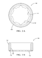
Fig. 2A is an elevation view of a first embodiment of an isolation ring in accordance with the present invention; -
Fig. 2B is a cross section of the first embodiment of an isolation ring in accordance with the present invention; -
Fig. 2C is an isometric view of the first embodiment of an isolation ring in accordance with the present invention; -
Fig. 2D is a second isometric view of the first embodiment of an isolation ring in accordance with the present invention; -
Fig. 3A is an isometric view of a second embodiment of an isolation ring in accordance with the present invention; -
Fig. 3B is a cross section of the second embodiment of an isolation ring in accordance with the present invention; -
Fig. 4 is a cross section of a third embodiment of an isolation ring in accordance with the present invention; -
Fig. 5 is a cross section of a fourth embodiment of an isolation ring in accordance with the present invention; -
Fig. 6 is a cross section of a fifth embodiment of an isolation ring in accordance with the present invention; -
Fig. 7 is a cross section of a sixth embodiment of an isolation ring in accordance with the present invention; -
Fig. 8 is a cross section of a seventh embodiment of an isolation ring in accordance with the present invention installed in a cylinder head-fuel injector assembly; -
Fig. 9 is a cross section of an eighth embodiment of an isolation ring in accordance with the present invention installed in a cylinder head-fuel injector assembly; and -
Fig. 10 is a cross section of a ninth embodiment of an isolation ring in accordance with the present invention installed in a cylinder head-fuel injector assembly. - Referring to
Fig. 1 , a fuel-injector-engine component assembly illustrated as fuel injector-cylinder head assembly 20 ofinternal combustion engine 22 includesfuel injector 24, an engine component illustrated ascylinder head 26, andisolation ring 28 assembled therebetween. Fuel injector-cylinder head assembly 20 extends along anaxis 30. -
Fuel injector 24 extends alongaxis 30 and includessolenoid housing 32 andinjector tip 34 axially extending fromsolenoid housing 32.Solenoid housing 32 includes fuelinjector stop surface 35 facing axially downwardly.Cylinder head 26 includes stepped bore 36 defined alongaxis 30 and having stepped bore stopsurface 37 facing axially upwardly andcenter opening 38.Fuel injector 24 is assembled in stepped bore 36 ofcylinder head 26 such that stepped bore 36 ofcylinder head 26 accommodatessolenoid housing 32 offuel injector 24 and such thatinjector tip 34 extends through center opening 38 ofcylinder head 26. Whenfuel injector 24 is assembled within stepped bore 36, fuelinjector stop surface 35 and stepped bore stopsurface 37 axially oppose each other and define predeterminedannular space 39. In operation,fuel injector 24 is subject to high frequency vibrations or axial pulses that tend to drive fuelinjector stop surface 35 and stepped bore stopsurface 37 axially together.Fuel injector 24 may be, but is not limited to, a fuel injector for direct injection as shown inFig. 1 . -
Isolation ring 28 is positioned within stepped bore 36 such thatisolation ring 28 is positioned adjacent to solenoidhousing 32 and encirclingfuel injector 24 within predeterminedannular space 39. Accordingly,isolation ring 28 hasouter circumference 40 that fits into stepped bore 36 and that is wider thancenter opening 38.Isolation ring 28 further includescenter aperture 42 adapted to receivefuel injector 24 therethrough.Isolation ring 28 includesrigid support member 44 andisolation member 46.Support member 44 may be made of any material that is capable of withstanding the axial loads provided byfuel injector 24 while in operation and is preferably made of metal.Isolation member 46 is a compliant, resilient material and may be a rubber material such as fluorocarbon. Although not shown, it should now be understood thatsupport member 44 may be formed integrally withfuel injector 24 or formed separately and attached tofuel injector 24. -
Support member 44 includesrecess 48 extending axially intosupport member 44 fromfirst surface 50. Beforeisolation ring 28 is assembled into fuel injector-head assembly 20,isolation member 46 is in an uncompressed or free state. In the uncompressed state,isolation member 46 extends axially outward fromfirst surface 50. For example,isolation member 46 may extend axially outward from first surface 50 a distance of about 1 millimeter. Whenisolation ring 28 is installed into fuel injector-head assembly 20, but not yet subjected to fuel pressure load fromfuel injector 24,isolation member 46 may be compressed slightly. For example,isolation member 46 may now be compressed such thatisolation member 46 may extend axially outward from first surface 50 a distance of about .4 millimeters.Isolation member 46 may be compressed further wheninternal combustion engine 22 is running at low to moderate loads, thereby requiring lower fuel pressure than the maximum fuel pressure it is capable of realizing. For example,isolation member 46 may now be compressed such thatisolation member 46 may extend axially outward from first surface 50 a distance of about .1-.2 millimeters. Wheninternal combustion engine 22 is running at higher loads, thereby requiring higher fuel pressure than at lower loads,isolation member 46 may now be compressed such thatisolation member 46 no longer extends axially outward fromfirst surface 50. In other words,first surface 50 is now in contact with stepped bore stopsurface 37 ofcylinder head 26.Isolation ring 28 may therefore be designed to allowsupport member 44 to contactcylinder head 26 at a predetermined fuel pressure. It is now understood thatisolation member 46 is the only portion ofisolation ring 28 in contact withcylinder head 26 except in instances when fuel pressure applied tofuel injector 24 is at or above the predetermined fuel pressure. Therefore, the material characteristics ofisolation member 46 reduce noise at lower to moderate engine loads, which is when noise reduction is most critical. Additionally, the material characteristics ofisolation member 46 include insulative potential to isolate heat from being transmitted fromcylinder head 26 tofuel injector 24 at lower to moderate engine loads which is the loadinginternal combustion engine 22 predominantly experiences. When fuel pressure is at its highest levels,support member 44 preventsisolation member 46 from being over compressed. -
Recess 48 may be arranged to allowisolation member 46 to deform in order allow for axial compression ofisolation member 46 as the axial load applied thereto increases.Isolation member 46 may also be arranged to deform in order to allow for axial compression thereof as the axial load applied thereto increases. This will be described in more detail with the description of the embodiments that follow. - Now referring to
Figs. 2A-2D , a first embodiment ofisolation ring 128 is shown in an uncompressed state.Isolation member 146 may include a plurality ofprotrusions 152 that extend radially inward therefrom.Protrusions 152 serve to form an interference fit withfuel injector 24 in order to retainisolation ring 128 tofuel injector 24 beforeisolation ring 128 andfuel injector 24 are assembled intocylinder head 26. - Still referring to
Figs. 2A-2D ,recess 148 is arranged to allowisolation member 146 to expand radially inward and radially outward whenisolation member 146 is compressed axially. This is accomplished by allowingisolation member 146 to expand radially outward because radial clearance is provided betweensupport member 144 andisolation member 146. This is also accomplished by allowingisolation member 146 to expand radially inward becauserecess 148 extends to centeraperture 142, thereby boundingisolation member 146 only radially outward bysupport member 144. - Now referring to
Figs. 3A and 3B , a second embodiment ofisolation ring 228 is shown in an uncompressed state.Isolation ring 228 is different fromisolation ring 128 of the first embodiment in that the height ofisolation member 246 is substantially increased.Isolation member 246 may include a plurality ofprotrusions 252 that extend radially inward therefrom.Protrusions 252 serve to form an interference fit withfuel injector 24 in order to retainisolation ring 228 tofuel injector 24 beforeisolation ring 228 andfuel injector 24 are assembled intocylinder head 26. In addition to, or in alternative toprotrusions 252,support member 244 may include a plurality offingers 254 that extend radially inward therefrom.Fingers 254 serve to form an interference fit withfuel injector 24 in order to retainisolation ring 228 tofuel injector 24 beforeisolation ring 228 andfuel injector 24 are assembled intocylinder head 26. - In the second embodiment,
support member 244 may be made of stamped sheet metal. This may result inhollow cavity 256 being formed at the end ofsupport member 244opposite recess 248.Isolation member 246 may then be injection molded to supportmember 244. In this way,isolation member 246 may be retained to supportmember 244. - Still referring to
Figs. 3A and 3B ,recess 248 is arranged to allowisolation member 246 to expand radially inward whenisolation member 246 is compressed axially. This is accomplished by allowingisolation member 246 to expand radially inward becauserecess 248 extends to centeraperture 242, thereby boundingisolation member 246 only radially outward bysupport member 244. - Now referring to
Fig. 4 , a third embodiment is shown in an uncompressed state in whichisolation ring 328 is shown at only a single radial location. In this embodiment,recess 348bounds isolation member 346 both radially outward and radially inward over most of the axial length ofisolation member 346.Recess 348 is arranged to allowisolation member 346 to expand radially outward and radially inward whenisolation member 346 is compressed axially. This is accomplished by providingexpansion cavities 358 at the open end ofsupport member 344. - Now referring to
Fig. 5 , a fourth embodiment is shown in an uncompressed state in whichisolation ring 428 is shown at only a single radial location. In this embodiment,recess 448bounds isolation member 446 both radially outward and radially inward over only a small portion of the axial length ofisolation member 446.Recess 448 is arranged to allowisolation member 446 to expand radially outward and radially inward whenisolation member 446 is compressed axially. This is accomplished by providingexpansion cavities 458 at the open end ofsupport member 444. - Now referring to
Fig. 6 , a fifth embodiment is shown in whichisolation ring 528 is shown in an uncompressed state at only a single radial location. In this embodiment,recess 548bounds isolation member 546 both radially outward and radially inward over a portion of the axial length ofisolation member 546.Recess 548 andisolation member 546 are arranged to allowisolation member 546 to expand radially outward, radially inward, and axially upward whenisolation member 546 is compressed axially. This is accomplished by providingexpansion cavities 558. The barrel-shape cross sectional ofisolation member 546 in combination with the straight sides and domed top ofsupport member 544form expansion cavities 558. - Now referring to
Fig. 7 , a sixth embodiment is shown in whichisolation ring 628 is shown in an uncompressed state at only a single radial location. In this embodiment,recess 648bounds isolation member 646 both radially outward and radially inward over a portion of the axial length ofisolation member 646.Recess 648 andisolation member 646 are arranged to allowisolation member 646 to expand radially outward and radially inward whenisolation member 646 is compressed axially. This is accomplished by providingexpansion cavities 658.Grooves 664 andchamfers 666 formed inisolation member 646 in combination with the straight sides ofsupport member 644form expansion cavities 658. - Now referring to
Fig. 8 , a seventh embodiment is shown in whichisolation ring 728 is inverted from the embodiments previously shown. That is,isolation member 746contacts fuel injector 24 rather thancylinder head 26. - Now referring to
Fig. 9 , an eighth embodiment is shown in whichisolation ring 828 allowsisolation member 846 to contact bothfuel injector 24 andcylinder head 26. This is accomplished by the support member comprisinginner ring 860 andouter ring 862 withisolation member 846 contained therebetween. In the uncompressed state,isolation member 846 extends axially outward from both ends of inner andouter rings isolation ring 828 may include only one of the inner andouter rings outer rings 862 may be integrally formed withfuel injector 24 or affixed thereto in order to form an annular recess for receivingisolation member 846 therewithin. - Now referring to
Fig. 10 , a ninth embodiment is shown in which the isolation ring does not include a support member attached thereto. In this embodiment, the support member is integral withfuel injector 24. In this way, the interaction between features offuel injector 24 andcylinder head 26 limit the amount of axial compression applied toisolation member 946. Specifically,surface 968 offuel injector 24 is allowed to come into contact withcorner 970 ofcylinder head 26 when fuel pressure compressisolation member 946 sufficiently. - While stepped bore 36 has been described as being formed in
cylinder head 26 ofinternal combustion engine 22, it should be now understood that the stepped bore could be located in other elements of the internal combustion which may receive a fuel injector therein. For example, the stepped bore could be formed in the intake manifold of a port injection fuel injection engine. Accordingly, fuel injector-cylinder head assembly 20 may be generically referred to as a fuel injector-engine component assembly where the engine component is any element of the engine with a stepped bore in which the fuel injector is installed. - While the isolation ring has been described as having one isolation member, it should now be understood that multiple isolation members may be used. One example may be a first isolation member for interfacing with the fuel injector and a second isolation member for interfacing with the cylinder head.
- While the invention has been described by reference to various specific embodiments, it should be understood that numerous changes may be made within the spirit and scope of the inventive concepts described. Accordingly, it is intended that the invention not be limited to the described embodiments, but rather only to the extent set forth in the claims that follow.
Claims (13)
- A fuel injector-engine component assembly (20) for an internal combustion engine (22), said fuel injector-engine component assembly (20) comprising:an engine component (26) with a stepped bore (36) defined along an axis (30), said stepped bore (36) having a stepped bore stop surface (37) facing axially upward;a fuel injector (24) in said stepped bore (36) and extending along said axis (30), said fuel injector (24) having a fuel injector stop surface (35) facing axially downwardly and axially opposed to said stepped bore stop surface (37) to define a predetermined annular space (39), said fuel injector (24) being subject in operation to axial pulses that tend to drive said fuel injector stop surface (35) and said stepped bore stop surface (37) together; andan isolation ring (28, 128, 228, 328, 428, 528, 628, 728, 828) disposed in said predetermined annular space (39) and axially between said stepped bore stop surface (37) and said fuel injector stop surface (35) for axially isolating said fuel injector (24) from said engine component (26), said isolation ring (28, 128, 228, 328, 428, 528, 628, 728, 828) comprising:a rigid support member (44, 144, 244, 344, 444, 544, 644, 744, 860, 862, 968) for limiting the axial motion of said stepped bore stop surface (37) and said fuel injector stop surface (35) together to a predetermined, limited degree; anda resilient and compliant isolation member (46, 146, 246, 346, 446, 546, 646, 746, 846, 946) located axially between said stepped bore stop surface (37) and said fuel injector stop surface (35), said isolation member (46, 146, 246, 346, 446, 546, 646, 746, 846, 946) having a sufficient resilience, compressibility, and insulative potential to provide at least one of acoustic and thermal isolation between said fuel injector (24) and said engine component (26) below a predetermined pressure of said fuel injector (24).
- A fuel injector-engine component assembly (20) in accordance with claim 1, wherein said support member (44, 144, 244, 344, 444, 544, 644, 744, 860, 862, 968) limits axial compression of said isolation member (46, 146, 246, 346, 446, 546, 646, 746, 846, 946) at or above said predetermined pressure of said fuel injector (24).
- A fuel injector-engine component assembly (20) in accordance with claim 1 or claim 2, wherein said support member (44, 144, 244, 344, 444, 544, 644, 744, 860, 862) includes a recess (48, 148, 248, 348, 448, 548, 648) extending axially thereinto for receiving a portion of said isolation member (46, 146, 246, 346, 446, 546, 646, 746, 846) therewithin.
- A fuel injector-engine component assembly (20) in accordance with any one of claims 1, 2 or 3, wherein a portion of said isolation member (46, 146, 246, 346, 446, 546, 646, 746, 846) extends axially away from said support member (44, 144, 244, 344, 444, 544, 644, 744, 860, 862) below said predetermined pressure of said fuel injector (24).
- A fuel injector-engine component assembly (20) in accordance with any preceding claim, wherein said isolation member (46, 146, 246, 346, 446, 546, 646, 746, 846, 946) expands radially in response to axial compression thereof.
- A fuel injector-engine component assembly (20) in accordance with any preceding claim, wherein an expansion cavity (358, 458, 558, 658) is formed between said isolation member (346, 446, 546, 646) and said support member (344, 444, 544, 644) to allow radial expansion of said isolation member (346, 446, 546, 646) in response to axial compression thereof.
- A fuel injector-engine component assembly (20) in accordance with any preceding claim, wherein said isolation member (146, 246) includes a plurality of protrusions (152, 252) extending radially inward therefrom that form an interference fit with said fuel injector (24) to retain said isolation ring (128, 228) to said fuel injector (24) prior to said fuel injector (24) being received within said stepped bore (36) of said engine component (26).
- A fuel injector-engine component assembly (20) in accordance with any preceding claim, wherein said support member (244) includes a plurality of fingers (254) that extend radially inward therefrom that form an interference fit with said fuel injector (24) to retain said isolation ring (228) to said fuel injector (24) prior to said fuel injector (24) being received within said stepped bore (36) of said engine component (26).
- A fuel injector-engine component assembly (20) in accordance with any preceding claim, wherein one of said isolation member (46, 146, 246, 346, 446, 546, 646, 746, 846, 946) and said support member (44, 144, 244, 344, 444, 544, 644, 744, 860, 862, 968) is in contact with said fuel injector (24) and the other of said isolation member (46, 146, 246, 346, 446, 546, 646, 746, 846, 946) and said support member (44, 144, 244, 344, 444, 544, 644, 744, 860, 862, 968) is in contact with said engine component (26) below said predetermined pressure of said fuel injector (24).
- A fuel injector-engine component assembly (20) in accordance with claim 1
wherein said support member (44, 144, 244, 344, 444, 544, 644, 744, 860, 862, 968) is in contact with both said fuel injector (24) and said engine component (26) at or above said predetermined pressure of said fuel injector (24). - A fuel injector-engine component assembly (20) in accordance with any preceding claim, wherein said isolation member (846, 946) is in contact with said fuel injector (24) and said engine component (26) below said predetermined pressure of said fuel injector.
- A fuel injector-engine component assembly (20) in accordance with any preceding claim, wherein said support member (860, 862, 968) is in contact with said fuel injector (24) and said engine component (26) at or above said predetermined pressure of said fuel injector (24).
- A fuel injector-engine component assembly (20) in accordance with any preceding claim wherein said support member (860) is a first support member and wherein said isolation ring (828) includes a second rigid support member (862) for limiting the axial motion of said stepped bore stop surface (37) and said fuel injector stop surface (35) together to a predetermined, limited degree.
Applications Claiming Priority (2)
| Application Number | Priority Date | Filing Date | Title |
|---|---|---|---|
| US33062910P | 2010-05-03 | 2010-05-03 | |
| US13/097,444 US20110265767A1 (en) | 2010-05-03 | 2011-04-29 | Isolater for fuel injector |
Publications (2)
| Publication Number | Publication Date |
|---|---|
| EP2385242A2 true EP2385242A2 (en) | 2011-11-09 |
| EP2385242A3 EP2385242A3 (en) | 2013-07-24 |
Family
ID=44352228
Family Applications (1)
| Application Number | Title | Priority Date | Filing Date |
|---|---|---|---|
| EP11164536.2A Withdrawn EP2385242A3 (en) | 2010-05-03 | 2011-05-03 | Isolator for fuel injector |
Country Status (2)
| Country | Link |
|---|---|
| US (1) | US20110265767A1 (en) |
| EP (1) | EP2385242A3 (en) |
Cited By (2)
| Publication number | Priority date | Publication date | Assignee | Title |
|---|---|---|---|---|
| WO2016045893A1 (en) * | 2014-09-23 | 2016-03-31 | Continental Automotive Gmbh | Adjustment device for a fuel injection valve and fuel-injection system |
| WO2016082982A1 (en) * | 2014-11-28 | 2016-06-02 | Robert Bosch Gmbh | Direct injection gas injector with an elastomer seal |
Families Citing this family (8)
| Publication number | Priority date | Publication date | Assignee | Title |
|---|---|---|---|---|
| FR2949247B1 (en) * | 2009-08-24 | 2011-09-16 | Renault Sa | SYSTEM FOR MOUNTING A RESONANT NEEDLE INJECTION DEVICE. |
| US8516996B2 (en) * | 2010-12-01 | 2013-08-27 | Ford Global Technologies | Direct fuel injection system for internal combustion engine with conical ring injector isolator |
| JP5270714B2 (en) * | 2011-04-27 | 2013-08-21 | トヨタ自動車株式会社 | Damping insulator for fuel injection valve |
| DE102014225976A1 (en) * | 2014-12-16 | 2016-06-16 | Robert Bosch Gmbh | Fuel injection device |
| JP2018062869A (en) * | 2016-10-11 | 2018-04-19 | 株式会社Soken | Fuel injection device and washer |
| US10746145B1 (en) * | 2019-05-08 | 2020-08-18 | Delphi Technologies Ip Limited | Isolator for fuel injector |
| EP4048876A4 (en) * | 2019-12-02 | 2023-11-15 | Cummins, Inc. | Grooved injector nozzle combustion shield |
| CN118451247A (en) * | 2021-10-19 | 2024-08-06 | 斯坦蒂内运营公司 | Axisymmetric injector compression load ring |
Citations (1)
| Publication number | Priority date | Publication date | Assignee | Title |
|---|---|---|---|---|
| US20020157648A1 (en) * | 1999-12-24 | 2002-10-31 | Ferdinand Reiter | Compensating element |
Family Cites Families (26)
| Publication number | Priority date | Publication date | Assignee | Title |
|---|---|---|---|---|
| US1970801A (en) * | 1932-04-26 | 1934-08-21 | Bosch Robert | Fuel injection nozzle for internal combustion engines |
| JPH09112697A (en) * | 1995-10-17 | 1997-05-02 | Mitsubishi Electric Corp | Seal ring |
| JP3033499B2 (en) * | 1996-08-22 | 2000-04-17 | 三菱自動車工業株式会社 | Cylinder head sealing device |
| DE19735665A1 (en) * | 1997-06-25 | 1999-01-07 | Bosch Gmbh Robert | Fuel injection system |
| DE10027662A1 (en) * | 2000-06-03 | 2001-12-06 | Bosch Gmbh Robert | Sealing unit for a fuel injection valve in a cylider head bore comprises a main body with an axial bore with an enlarged section which accommodates a sealing element |
| DE10038763A1 (en) * | 2000-08-09 | 2002-02-21 | Bosch Gmbh Robert | Compensation element for a fuel injector |
| DE10056005A1 (en) * | 2000-11-11 | 2002-05-16 | Bosch Gmbh Robert | Fuel injection valve, for an IC motor, has a ring seal at the connector to the fuel distribution line, with elasticity to compensate for shifts in position between the axes of the connector and the fuel injection valve |
| DE10108194A1 (en) * | 2001-02-21 | 2002-08-29 | Bosch Gmbh Robert | Sealing device for a fuel injector |
| DE10108467A1 (en) * | 2001-02-22 | 2002-09-05 | Bosch Gmbh Robert | fastening device |
| DE10109408A1 (en) * | 2001-02-28 | 2002-09-05 | Bosch Gmbh Robert | fastening device |
| DE10112665A1 (en) * | 2001-03-16 | 2002-09-19 | Bosch Gmbh Robert | Attachment device for fuel injection valve has clamping in form of flat component supported on sleeve about valve in contact with preferably metal collar of valve |
| DE10140797A1 (en) * | 2001-08-20 | 2003-07-31 | Bosch Gmbh Robert | Compensation element for a fuel injector |
| DE10158788A1 (en) * | 2001-11-30 | 2003-06-12 | Bosch Gmbh Robert | fuel injection system |
| JP3997946B2 (en) * | 2002-07-26 | 2007-10-24 | 株式会社デンソー | Fuel supply device |
| US6640784B1 (en) * | 2002-10-09 | 2003-11-04 | Robert Bosch Corporation | Spark ignition direct injection system |
| DE10338715B4 (en) * | 2003-08-22 | 2014-07-17 | Robert Bosch Gmbh | Compensation element for a fuel injection valve |
| DE10358913A1 (en) * | 2003-12-16 | 2005-09-01 | Robert Bosch Gmbh | Fuel injector |
| JP4634765B2 (en) * | 2004-09-16 | 2011-02-16 | 日産自動車株式会社 | Fuel injection valve mounting structure |
| DE102005011574A1 (en) * | 2005-03-14 | 2006-09-21 | Robert Bosch Gmbh | Intermediate element for a fuel injection valve |
| US20070113828A1 (en) * | 2005-11-22 | 2007-05-24 | Fonville Carl E | Fuel injector isolating and sealing member |
| US7591246B2 (en) * | 2006-01-17 | 2009-09-22 | Gm Global Technology Operations, Inc. | Isolated fuel delivery system |
| US7293550B2 (en) * | 2006-01-31 | 2007-11-13 | Gm Global Technology Operations, Inc. | Fuel injector isolation seat |
| DE602006012633D1 (en) * | 2006-06-01 | 2010-04-15 | Continental Automotive Gmbh | Compensation device and cylinder head assembly |
| US7484499B2 (en) * | 2007-04-03 | 2009-02-03 | Gm Global Technology Operations, Inc. | Combustion seal |
| US7827964B2 (en) * | 2009-01-14 | 2010-11-09 | Ford Global Technologies | Fuel injection system for internal combustion engine with injector isolator |
| US8069842B2 (en) * | 2009-07-02 | 2011-12-06 | Robert Bosch Gmbh | Injector mounting assembly |
-
2011
- 2011-04-29 US US13/097,444 patent/US20110265767A1/en not_active Abandoned
- 2011-05-03 EP EP11164536.2A patent/EP2385242A3/en not_active Withdrawn
Patent Citations (1)
| Publication number | Priority date | Publication date | Assignee | Title |
|---|---|---|---|---|
| US20020157648A1 (en) * | 1999-12-24 | 2002-10-31 | Ferdinand Reiter | Compensating element |
Cited By (4)
| Publication number | Priority date | Publication date | Assignee | Title |
|---|---|---|---|---|
| WO2016045893A1 (en) * | 2014-09-23 | 2016-03-31 | Continental Automotive Gmbh | Adjustment device for a fuel injection valve and fuel-injection system |
| US10619612B2 (en) | 2014-09-23 | 2020-04-14 | Continental Automotive Gmbh | Fuel injection valve and fuel-injection system |
| WO2016082982A1 (en) * | 2014-11-28 | 2016-06-02 | Robert Bosch Gmbh | Direct injection gas injector with an elastomer seal |
| US11162459B2 (en) | 2014-11-28 | 2021-11-02 | Robert Bosch Gmbh | Direct injection gas injector with an elastomer seal |
Also Published As
| Publication number | Publication date |
|---|---|
| EP2385242A3 (en) | 2013-07-24 |
| US20110265767A1 (en) | 2011-11-03 |
Similar Documents
| Publication | Publication Date | Title |
|---|---|---|
| EP2385242A2 (en) | Isolator for fuel injector | |
| US20090235898A1 (en) | Fuel injector isolator | |
| US8757128B2 (en) | Decoupling element for a fuel injection device | |
| CN101784787B (en) | Fuel injection device with compensating element | |
| US9347411B2 (en) | Decoupling element for a fuel injection device | |
| EP1959172B1 (en) | Lip type seal | |
| US7827964B2 (en) | Fuel injection system for internal combustion engine with injector isolator | |
| CN102282358B (en) | For the two-phase spring assembly of fuel injection system | |
| JP2003502573A (en) | Fuel injection valve | |
| CN105275668B (en) | Injectors, especially injection injectors for gaseous fuels | |
| KR102447583B1 (en) | Decoupling elements for fuel injectors | |
| JP2015521715A (en) | Piston type fuel pump | |
| JP6302486B2 (en) | FUEL INJECTION DEVICE HAVING FUEL GUIDING COMPONENT, FUEL INJECTION VALVE, AND CONNECTING MEMBER | |
| WO2017030060A1 (en) | Valve stem seal and sealing structure | |
| JP4407863B2 (en) | Sealing device | |
| US9938947B2 (en) | Decoupling element for a fuel injection device | |
| JP2015515577A (en) | Insulating element comprising a plurality of members, in particular for fuel injectors | |
| US9347412B2 (en) | Damping element for an arrangement of a cylinder head of an internal combustion engine and an injection valve | |
| US20160017855A1 (en) | Valve for controlling a fluid with increased sealing action | |
| CN109654283B (en) | Valves for metering fluids, especially gas valves | |
| CN216922321U (en) | Fuel injector | |
| CN218376600U (en) | Valve bridge and diesel engine with valve clearance compensation | |
| US9885331B2 (en) | Decoupling element for a fuel injection device | |
| CN107002597B (en) | Direct injection gas injector with elastomeric seal | |
| JP6121918B2 (en) | Vibration suppressing member and electromagnetic valve mounting structure using the same |
Legal Events
| Date | Code | Title | Description |
|---|---|---|---|
| AK | Designated contracting states |
Kind code of ref document: A2 Designated state(s): AL AT BE BG CH CY CZ DE DK EE ES FI FR GB GR HR HU IE IS IT LI LT LU LV MC MK MT NL NO PL PT RO RS SE SI SK SM TR |
|
| AX | Request for extension of the european patent |
Extension state: BA ME |
|
| PUAI | Public reference made under article 153(3) epc to a published international application that has entered the european phase |
Free format text: ORIGINAL CODE: 0009012 |
|
| PUAL | Search report despatched |
Free format text: ORIGINAL CODE: 0009013 |
|
| AK | Designated contracting states |
Kind code of ref document: A3 Designated state(s): AL AT BE BG CH CY CZ DE DK EE ES FI FR GB GR HR HU IE IS IT LI LT LU LV MC MK MT NL NO PL PT RO RS SE SI SK SM TR |
|
| AX | Request for extension of the european patent |
Extension state: BA ME |
|
| RIC1 | Information provided on ipc code assigned before grant |
Ipc: F02M 61/14 20060101AFI20130614BHEP Ipc: F02M 53/04 20060101ALI20130614BHEP |
|
| 17P | Request for examination filed |
Effective date: 20140124 |
|
| RAX | Requested extension states of the european patent have changed |
Extension state: ME Payment date: 20140124 Extension state: BA Payment date: 20140124 |
|
| RBV | Designated contracting states (corrected) |
Designated state(s): AL AT BE BG CH CY CZ DE DK EE ES FI FR GB GR HR HU IE IS IT LI LT LU LV MC MK MT NL NO PL PT RO RS SE SI SK SM TR |
|
| 17Q | First examination report despatched |
Effective date: 20140327 |
|
| STAA | Information on the status of an ep patent application or granted ep patent |
Free format text: STATUS: THE APPLICATION IS DEEMED TO BE WITHDRAWN |
|
| 18D | Application deemed to be withdrawn |
Effective date: 20160412 |