EP2385218A2 - Turbine housing for a turbocharger and corresponding turbocharger - Google Patents
Turbine housing for a turbocharger and corresponding turbocharger Download PDFInfo
- Publication number
- EP2385218A2 EP2385218A2 EP11163998A EP11163998A EP2385218A2 EP 2385218 A2 EP2385218 A2 EP 2385218A2 EP 11163998 A EP11163998 A EP 11163998A EP 11163998 A EP11163998 A EP 11163998A EP 2385218 A2 EP2385218 A2 EP 2385218A2
- Authority
- EP
- European Patent Office
- Prior art keywords
- spiral chamber
- turbine
- turbine housing
- angular segment
- mouth
- Prior art date
- Legal status (The legal status is an assumption and is not a legal conclusion. Google has not performed a legal analysis and makes no representation as to the accuracy of the status listed.)
- Granted
Links
- 238000002485 combustion reaction Methods 0.000 claims description 18
- 230000003247 decreasing effect Effects 0.000 claims 1
- 239000007789 gas Substances 0.000 description 73
- 239000002699 waste material Substances 0.000 description 5
- 239000003054 catalyst Substances 0.000 description 4
- 230000007423 decrease Effects 0.000 description 4
- 230000008901 benefit Effects 0.000 description 3
- 230000000295 complement effect Effects 0.000 description 3
- 230000001419 dependent effect Effects 0.000 description 3
- 230000000694 effects Effects 0.000 description 2
- 230000007704 transition Effects 0.000 description 2
- 241000277301 Esociformes Species 0.000 description 1
- 230000004913 activation Effects 0.000 description 1
- 230000001154 acute effect Effects 0.000 description 1
- 230000008859 change Effects 0.000 description 1
- 238000010276 construction Methods 0.000 description 1
- 238000007599 discharging Methods 0.000 description 1
- 238000010438 heat treatment Methods 0.000 description 1
- 230000004048 modification Effects 0.000 description 1
- 238000012986 modification Methods 0.000 description 1
- 239000012041 precatalyst Substances 0.000 description 1
- 230000003584 silencer Effects 0.000 description 1
Images

Classifications
-
- F—MECHANICAL ENGINEERING; LIGHTING; HEATING; WEAPONS; BLASTING
- F01—MACHINES OR ENGINES IN GENERAL; ENGINE PLANTS IN GENERAL; STEAM ENGINES
- F01D—NON-POSITIVE DISPLACEMENT MACHINES OR ENGINES, e.g. STEAM TURBINES
- F01D17/00—Regulating or controlling by varying flow
- F01D17/10—Final actuators
- F01D17/12—Final actuators arranged in stator parts
- F01D17/14—Final actuators arranged in stator parts varying effective cross-sectional area of nozzles or guide conduits
- F01D17/148—Final actuators arranged in stator parts varying effective cross-sectional area of nozzles or guide conduits by means of rotatable members, e.g. butterfly valves
-
- F—MECHANICAL ENGINEERING; LIGHTING; HEATING; WEAPONS; BLASTING
- F01—MACHINES OR ENGINES IN GENERAL; ENGINE PLANTS IN GENERAL; STEAM ENGINES
- F01D—NON-POSITIVE DISPLACEMENT MACHINES OR ENGINES, e.g. STEAM TURBINES
- F01D17/00—Regulating or controlling by varying flow
- F01D17/10—Final actuators
- F01D17/12—Final actuators arranged in stator parts
- F01D17/18—Final actuators arranged in stator parts varying effective number of nozzles or guide conduits, e.g. sequentially operable valves for steam turbines
-
- F—MECHANICAL ENGINEERING; LIGHTING; HEATING; WEAPONS; BLASTING
- F01—MACHINES OR ENGINES IN GENERAL; ENGINE PLANTS IN GENERAL; STEAM ENGINES
- F01D—NON-POSITIVE DISPLACEMENT MACHINES OR ENGINES, e.g. STEAM TURBINES
- F01D9/00—Stators
- F01D9/02—Nozzles; Nozzle boxes; Stator blades; Guide conduits, e.g. individual nozzles
- F01D9/026—Scrolls for radial machines or engines
-
- F—MECHANICAL ENGINEERING; LIGHTING; HEATING; WEAPONS; BLASTING
- F02—COMBUSTION ENGINES; HOT-GAS OR COMBUSTION-PRODUCT ENGINE PLANTS
- F02B—INTERNAL-COMBUSTION PISTON ENGINES; COMBUSTION ENGINES IN GENERAL
- F02B37/00—Engines characterised by provision of pumps driven at least for part of the time by exhaust
- F02B37/02—Gas passages between engine outlet and pump drive, e.g. reservoirs
- F02B37/025—Multiple scrolls or multiple gas passages guiding the gas to the pump drive
-
- F—MECHANICAL ENGINEERING; LIGHTING; HEATING; WEAPONS; BLASTING
- F02—COMBUSTION ENGINES; HOT-GAS OR COMBUSTION-PRODUCT ENGINE PLANTS
- F02B—INTERNAL-COMBUSTION PISTON ENGINES; COMBUSTION ENGINES IN GENERAL
- F02B37/00—Engines characterised by provision of pumps driven at least for part of the time by exhaust
- F02B37/12—Control of the pumps
- F02B37/22—Control of the pumps by varying cross-section of exhaust passages or air passages, e.g. by throttling turbine inlets or outlets or by varying effective number of guide conduits
-
- F—MECHANICAL ENGINEERING; LIGHTING; HEATING; WEAPONS; BLASTING
- F02—COMBUSTION ENGINES; HOT-GAS OR COMBUSTION-PRODUCT ENGINE PLANTS
- F02C—GAS-TURBINE PLANTS; AIR INTAKES FOR JET-PROPULSION PLANTS; CONTROLLING FUEL SUPPLY IN AIR-BREATHING JET-PROPULSION PLANTS
- F02C6/00—Plural gas-turbine plants; Combinations of gas-turbine plants with other apparatus; Adaptations of gas- turbine plants for special use
- F02C6/04—Gas-turbine plants providing heated or pressurised working fluid for other apparatus, e.g. without mechanical power output
- F02C6/10—Gas-turbine plants providing heated or pressurised working fluid for other apparatus, e.g. without mechanical power output supplying working fluid to a user, e.g. a chemical process, which returns working fluid to a turbine of the plant
- F02C6/12—Turbochargers, i.e. plants for augmenting mechanical power output of internal-combustion piston engines by increase of charge pressure
-
- F—MECHANICAL ENGINEERING; LIGHTING; HEATING; WEAPONS; BLASTING
- F05—INDEXING SCHEMES RELATING TO ENGINES OR PUMPS IN VARIOUS SUBCLASSES OF CLASSES F01-F04
- F05B—INDEXING SCHEME RELATING TO WIND, SPRING, WEIGHT, INERTIA OR LIKE MOTORS, TO MACHINES OR ENGINES FOR LIQUIDS COVERED BY SUBCLASSES F03B, F03D AND F03G
- F05B2220/00—Application
- F05B2220/40—Application in turbochargers
-
- F—MECHANICAL ENGINEERING; LIGHTING; HEATING; WEAPONS; BLASTING
- F05—INDEXING SCHEMES RELATING TO ENGINES OR PUMPS IN VARIOUS SUBCLASSES OF CLASSES F01-F04
- F05D—INDEXING SCHEME FOR ASPECTS RELATING TO NON-POSITIVE-DISPLACEMENT MACHINES OR ENGINES, GAS-TURBINES OR JET-PROPULSION PLANTS
- F05D2220/00—Application
- F05D2220/40—Application in turbochargers
-
- Y—GENERAL TAGGING OF NEW TECHNOLOGICAL DEVELOPMENTS; GENERAL TAGGING OF CROSS-SECTIONAL TECHNOLOGIES SPANNING OVER SEVERAL SECTIONS OF THE IPC; TECHNICAL SUBJECTS COVERED BY FORMER USPC CROSS-REFERENCE ART COLLECTIONS [XRACs] AND DIGESTS
- Y02—TECHNOLOGIES OR APPLICATIONS FOR MITIGATION OR ADAPTATION AGAINST CLIMATE CHANGE
- Y02T—CLIMATE CHANGE MITIGATION TECHNOLOGIES RELATED TO TRANSPORTATION
- Y02T10/00—Road transport of goods or passengers
- Y02T10/10—Internal combustion engine [ICE] based vehicles
- Y02T10/12—Improving ICE efficiencies
Abstract
Description
- The present invention relates in general to a supercharger, also known as a turbocharger, arranged to increase the effect of a combustion engine, a turbine of the supercharger being driven by the exhaust gases of the combustion engine, which turbine is connected to a compressor impeller of the supercharger, which compressor impeller compress the intake air of the combustion engine. In particular the present invention relates to a turbine housing for a supercharger, which turbine housing comprises an inlet opening, a turbine seat and a race extending from said inlet opening to said turbine seat. Furthermore, said race comprises a first spiral chamber which mouth in said turbine seat as well as a second spiral chamber which mouth in said turbine seat. In a second aspect the present invention relates to a supercharger comprising such a turbine housing.
- Known superchargers, or turbochargers, belong more or less exclusively to one of the following three basic types of superchargers. Superchargers presenting a turbine housing having one single spiral chamber, a turbine housing having two parallel spiral chambers, or a turbine housing having variable geometry.
- In a turbine housing having one single spiral chamber the spiral chamber presents an inlet having a small area or an inlet having a large area in relation to the radius of the inlet of the spiral chamber, usually defined as small and large A/R-ratio, respectively. Turbine housing having a spiral chamber presenting a small inlet area in relation to the radius of the inlet of the spiral chamber are arranged to cause overcharge already at small exhaust gas flows, which as a rule coincide with low engine speed, but at big exhaust gas flows, which as a rule coincide with high engine speed, a large back pressure will be created in this type of turbine housing whereupon a large amount of the exhaust gas flow will be released via a waste gate and thereby a desired overcharge will not be attained at high engine speed. Turbine housing having one spiral chamber presenting a large inlet area in relation to the radius of the inlet of the spiral chamber are on the other hand arranged to create overcharge at high engine speed and large exhaust gas flow. However, this type of turbine housing presents worse efficiency or large overcharge delay which implies that none overcharge takes place at low engine speed and small exhaust gas flow.
- In a turbine housing having parallel spiral chambers the turbine housing comprises two spiral chambers, which are separated by a radially extending wall and which have the same or different inlet areas and/or radius at the inlet thereof. However, it shall be pointed out that the common inlet area of the two spiral chambers in relation to the radius of the inlet of the spiral chambers usually is classified as large by comparison with a turbine housing having one single spiral chamber, thus the turbine housing of this type is suitable for large exhaust gas flow and high engine speed. Furthermore, both the first spiral chamber and the second spiral chamber mouth in parallel with each other around the entire turbine seat of the turbine housing. The function of the radially extending wall is to guide the exhaust gas flow coming from a first set of complementary cylinders to one spiral chamber and the exhaust gas flow coming from a second set of complementary cylinders to the other spiral chamber. By having only complementary cylinders, i.e. cylinders not having their exhaust gas outlet valves open at the same time, operatively connected to each other no back flow takes place from a first cylinder to a second cylinder having partly overlapping cycle with said first cylinder. In theory the turbine is thus alternately affected by the exhaust gas flow from one and the other spiral chamber, which gives a better utilization of the exhaust gas pulse energy even at low engine speed. Thus, a turbine housing having parallel spiral chambers provide a larger engine speed range within which a desired overcharge takes place, in relation to a turbine housing having one single spiral chamber.
- In a turbine housing having variable geometry a great number of vanes are arranged at the interface between the spiral chamber and the turbine seat. The vanes are maneuverably movable between a more or less tangential position in relation to the turbine seat and a more or less radial position in relation to the turbine seat. At low engine speed and small exhaust gas flow the vanes are moved to the tangential position and at high engine speed and large exhaust gas flow the vanes are moved to the radial position. Thanks to the variable geometry a desired overcharge takes place already at very low engine speed at the same time as a desired overcharge also takes place at high engine speed. However, this solution is very expensive and construction wise complicated due to the great number of small movable parts in combination with high operational temperatures existing in turbine housing during operation. This applies in special to Otto-engines generally having higher exhaust gas temperatures than diesel engines. Thus, a turbine housing having variable geometry is uncommon in connection with Otto-engines.
- The present invention aims at obviating the aforementioned disadvantages and failings of previously known turbine housing and at providing an improved turbine housing. A primary object of the present invention is to provide an improved turbine housing of the initially defined type, which provide desired overcharge at small as well as large exhaust gas flows and thereby at low and high engine speed, respectively.
- Another object of the present invention is to provide a turbine housing comprising few or none moveable parts.
- It is another object of the present invention to provide a turbine housing being arranged to operate at high operational temperatures.
- According to the invention at least the primary object is attained by the means of the initially defined turbine housing, which is characterized in that both the first spiral chamber and the second spiral chamber mouth in a first angular segment of the turbine seat, the axial height of the mouth into the turbine seat of the second spiral chamber in said first angular segment is bigger in the end of the first angular segment than in the beginning thereof seen in a flow direction, and in that the A/R-ratio of the first spiral chamber is smaller than the common A/R-ratio of the first spiral chamber and the second spiral chamber.
- Thus, the present invention is based on the understanding that in the beginning of the turbine seat, seen in the flow direction, the first spiral chamber has a large mouth into the turbine seat in relation to the mouth of the second spiral chamber, and thereto the first spiral chamber presents an optimized geometry for small exhaust gas flow. This results in that the exhaust gas flow in the first spiral chamber is provided with a relatively high speed and an optimized attack angle for small exhaust gas flow, that is the exhaust gas flow is more tangentially directed in relation to the turbine, and can affect a large part of or the entire axially accessible height of the turbine in the turbine seat at the beginning of the turbine seat, seen in the flow direction. Furthermore, the present invention is based on the understanding that in the downstream direction in the first angular segment the mouth into the turbine seat of the second spiral chamber and thereto the second spiral chamber presents an optimized geometry for large exhaust gas flow. This results in that the exhaust gas flow in the second spiral chamber is provided with an optimized speed and an optimized attack angle for large exhaust gas flow, that is the exhaust gas flow is more radially directed in relation to the turbine than the exhaust gas flow of the first spiral chamber, and can affect a large part of or the entire axially accessible height of the turbine in the turbine seat at the end of the turbine seat seen in the flow direction.
- Preferred embodiments of the present invention are further defined in the dependent claims.
- Preferably the second spiral chamber comprises a maneuverable flow regulator. This entails that the second spiral chamber can be entirely or partly closed at for instance small exhaust gas flow, this presuppose that the exhaust gases from all working cylinders of the combustion engine concerned can be lead both to the first spiral chamber and to the second spiral chamber.
- According to a preferred embodiment the first spiral chamber comprises a maneuverable flow regulator. This entails that the first spiral chamber can be entirely or partly closed. The advantage of being able to close the first spiral chamber and the second spiral chamber is among other things that at cold starting of the engine the exhaust gases can be lead past the supercharger and directly to a catalyst, or a pre catalyst, without first being chilled by the supercharger.
- Preferably an outer determining surface of the second spiral chamber is arranged outside an outer determining surface of the first spiral chamber seen in the radial direction. This entails an even more optimized speed of the exhaust gases in the first spiral chamber at small exhaust gas flow.
- Preferably the second spiral chamber presents a larger cross sectional area than the first spiral chamber in each radial cross section of the race. This entails that the second spiral chamber is optimized for large exhaust gas flow and the first spiral chamber is optimized for small exhaust gas flow.
- Preferably only the first spiral chamber mouth in a second angular segment of the turbine seat, which second angular segment seen in the flow direction is arranged downstream and adjacent an inlet of the turbine housing. Furthermore both the first spiral chamber and the second spiral chamber mouth in a first angular segment of the turbine seat seen in the flow direction, which first angular segment is arranged downstream and adjacent said second angular segment. More preferably the axial height of the mouth into the turbine seat of the second chamber in the first angular segment increases in the direction of said flow direction, and furthermore it is preferred that the axial height of the mouth into the turbine seat of the first spiral chamber in the first angular segment decreases in the direction of said flow direction. Thus, a successive decrease of the mouth into the turbine seat of the first chamber and a successive increase of the mouth into the turbine seat of the second chamber takes place.
- Preferably said second angular segment of the turbine seat is bigger than 40 degrees, preferably bigger than 80 degrees. Furthermore it is preferred that said first angular segment and said second angular segment of the turbine seat together is bigger than 300 degrees, preferably bigger than 340 degrees. It shall be pointed out that the second angular segment can be 0 degrees.
- Preferably the first spiral chamber and the second spiral chamber are separated from each other by means of a wall having a principally axial extension parallel to the flow direction at said inlet opening and in said second angular segment. Thereby the first spiral chamber is provided with an optimized geometry for small exhaust gas flow in the beginning of the first angular segment in which the mouth of the first spiral chamber constitute a dominating part, as well as in the second angular segment when it differ from 0 degrees.
- The object of the invention is also attained by means of the initially defined supercharger, which is characterized in that it comprises such a turbine housing.
- Other advantages and features of the invention will be apparent from the other dependent claims as well as from the following detailed description of preferred embodiments.
- A more complete understanding of the abovementioned and other features and advantages of the present invention will be apparent from the following detailed description of preferred embodiments in conjunction with the appended drawings, wherein:
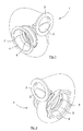
- Fig. 1
- is a perspective view of an inventive turbine housing, showing the outlet of the turbine housing,
- Fig. 2
- is a perspective view of the turbine housing according to
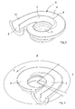
figure 1 , showing the turbine seat of the turbine housing, - Fig. 3
- is a perspective view of the left half of the turbine housing according to
figures 1 and 2 , showing the interior of the turbine housing, - Fig. 4
- is a perspective view of the right half of the turbine housing according to
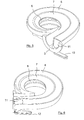
figures 1 and 2 , corresponding tofigure 3 , showing the interior of the turbine housing, - Fig. 5
- is a perspective view of a cross section of an alternative embodiment of the turbine housing comprising a flow regulator in closed condition, which cross section is taken closer to the outlet of the turbine housing than the cross section according to
figure 4 , - Fig. 6
- is a perspective view showing the flow regulator in the open condition, corresponding to
figure 5 , - Fig. 7
- is an elevated view of the inventive turbine housing showing the outlet of the turbine housing, as well as showing cross section placements,
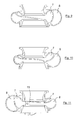
- Fig. 8
- is a cross sectional view of the turbine housing taken along line VIII in
figure 7 , - Fig. 9
- is a cross sectional view of the turbine housing taken along line IX in
figure 7 , - Fig. 10
- is a cross sectional view of the turbine housing taken along line X in
figure 7 , and - Fig. 11
- is a cross sectional view of the turbine housing taken along line XI in
figure 7 . - The present invention relates in general to a supercharger, also known as a turbocharger, arranged to increase the effect of a combustion engine, the supercharger being driven by the exhaust gas of the combustion engine and compress the intake air of the combustion engine.
- Reference is now made to
figures 1 and 2 . In particular the present invention relates to a turbine housing, generally designated 1. Theturbine housing 1 comprises aninlet opening 2, which is surrounded by aflange 3 which is arranged to be connected to a manifold or the like (not shown) leading the exhaust gas that flows out from the working cylinders of the combustion engine to theinlet opening 2 of theturbine housing 1. Furthermore, theturbine housing 1 comprises in a conventional way anoutlet opening 4 for discharging the exhaust gas from theturbine housing 1 to a conventional exhaust system (not shown), which may comprise a catalyst, a silencer, etc. Furthermore, theturbine housing 1 comprises aturbine seat 5 being arranged to house a rotatably arranged turbine (not shown), which is connected to and drive a compressor impeller that is rotatably arranged in a compressor housing, for overcharging the intake air of the working cylinders of the combustion engine. Theinlet opening 2 is in the shown embodiment tangentially arranged and theoutlet opening 4 is axially arranged, seen in relation to the rotational axis of the turbine. - Reference is now made to
figures 3 and 4 . Theinventive turbine housing 1 comprises a race, generally designated 6, extending from saidinlet opening 2 to saidturbine seat 5. Thus, therace 6 is arranged to lead the exhaust gas from theinlet opening 2 to theturbine seat 5 and the turbine. Furthermore, saidrace 6 comprises afirst spiral chamber 7 that mouth into saidturbine seat 5 and asecond spiral chamber 8 that mouth into saidturbine seat 5. Thefirst spiral chamber 7 and thesecond spiral chamber 8 are in the shown embodiment separated from each other along the entire length thereof by means of awall 9. Thewall 9 extends from aninlet 10 of theturbine housing 1. Theinlet 10 is a part of therace 6 and extends from theinlet opening 2 to the point where thefirst spiral chamber 7 mouth into theturbine seat 5. In one embodiment thewall 9 extends all the way from theinlet opening 2, and in other embodiments thewall 9 extends from between theinlet opening 2 and the point where thefirst spiral chamber 7 mouth into theturbine seat 5. Preferably thefirst spiral chamber 7 mouth into theturbine seat 5, seen in an axial direction, between theoutlet opening 4 of theturbine housing 1 and the mouth of thesecond chamber 8 into theturbine seat 5. However, the reverse relationship that thesecond spiral chamber 8 mouth into theturbine seat 5, seen in the axial direction, between theoutlet opening 4 of theturbine housing 1 and the mouth of thefirst spiral chamber 7 into theturbine seat 5 is possible. - It is essential for the invention that both the
first spiral chamber 7 and thesecond spiral chamber 8 mouth in a first angular segment β of theturbine seat 5, the axial height of the mouth into theturbine seat 5 of thesecond spiral chamber 8 in said first angular segment β being bigger at the end of the first angular segment β than in the beginning thereof seen in a flow direction F. - Furthermore, it is preferred that only the
first spiral chamber 7 mouth into a second angular segment α of theturbine seat 5, which second angular segment α is arranged downstream and adjacent theinlet 10 of theturbine housing 1, seen in the flow direction F. In other words, the second angular segment α starts in the point where thefirst spiral chamber 7 mouth into theturbine seat 5. In a preferred embodiment thewall 9 has a principally axial extension parallel to the flow direction F in said second angular segment α, and preferably in theinlet 10 as well. More preferably the part of thewall 9 that border on thefirst spiral chamber 7 presents a curved cross section, having its centre of curvature radially inside thewall 9, in said second angular segment α and/or in theinlet 10, which entail a soft transition between thewall 9 and the other surfaces delimiting thefirst spiral chamber 7, which in its turn contribute to decrease the friction in thefirst spiral chamber 7. Furthermore, it is also preferred that the part of thewall 9 that border on thesecond spiral chamber 8 presents a curved cross section, having its centre of curvature radially inside thewall 9, in said second angular segment α and/or in theinlet 10, and furthermore has a soft transition to the other surfaces delimiting thesecond spiral chamber 8. This entail that thesecond spiral chamber 8 obtain a so called cobra-bend (seefigures 8 and9 ), which provide minimal turbulence in the exhaust gas flow. However, it shall be pointed out that any conceivable cross section may be used in thefirst spiral chamber 7 as well as in thesecond spiral chamber 8. - The manifold, or the like, that is arranged to be connected to the
flange 3 of theinlet opening 2 of theturbine housing 1 as described above, comprises either common or divided supply of exhaust gas to theturbine housing 1. In the case of common supply all the exhaust gases that shall be lead to the turbine housing are lead from the combustion engine to theturbine housing 1 as one single exhaust gas flow, where a part of the exhaust gases flow into thefirst spiral chamber 7 and the remaining part of the exhaust gases flow into thesecond spiral chamber 8. Furthermore, theturbine housing 1 may in the case of common supply comprise different throttles or flow regulators in order to control the flow to any, both of none of thefirst spiral chamber 7 and thesecond spiral chamber 8, which will be described below. In the case of divided supply the exhaust gas from any or some of the working cylinders of the combustion engine is lead to thefirst spiral chamber 7 and from any or some of the working cylinders of the combustion engine to thesecond spiral chamber 8. - Reference is now made to
figures 5 and 6 , in which an alternative embodiment of theturbine housing 1 according tofigures 3 and 4 is shown. Theturbine housing 1 according to the alternative, preferred embodiment comprises, in addition to that described in connection withfigures 1-4 , amaneuverable flow regulator 11 arranged in thesecond spiral chamber 8. Infigure 5 theflow regulator 11 is shown in a thesecond spiral chamber 8 closed condition, and infigure 6 theflow regulator 11 is shown in a thesecond spiral chamber 8 open condition. It shall be pointed out that theflow regulator 11 preferably can occupy all positions between the closed position and the open position. Theflow regulator 11 is in the shown embodiment turnably movable between the closed position and the open position, and maneuverable by means of alever 12, however any equivalent maneuvering is conceivable. Opening and closing of theflow regulator 11 may for instance be connected to the rotational speed of the combustion engine, a position and/or a movement of a throttle lever, existing exhaust gas pressure in theturbine housing 1 or in any other suitable part of the exhaust system leading from the combustion engine, etc. According to an alternative embodiment the flow regulator is designed as a pressure controlled non return valve (not shown), that automatically opens when a specific pressure is obtained at for instance theinlet opening 2 of theturbine housing 1. It shall be pointed out that when theflow regulator 11 is in the closed position, it do not necessarily need to seal thesecond spiral chamber 8 entirely but a gap between the inner surface of thesecond spiral chamber 8 and theflow regulator 11 is allowed. Preferably theflow regulator 11 shall cover at least 80% of the cross sectional area of thesecond spiral chamber 8 at theflow regulator 11, preferably at least 90%. Thus, no expensive or complicated seat for theflow regulator 11 is needed. Theflow regulator 11 in thesecond spiral chamber 8 may be used as a maneuverable waste gate for thefirst spiral chamber 7 in order to even out the pressure during the pressure raising phase in thefirst spiral chamber 7, instead of using a conventional waste gate which allows the exhaust gas to bypass the supercharger when the backpressure in thefirst spiral chamber 7 of theturbine housing 1 is to high. A conventional waste gate may be used in a conventional way in order to even out the pressure when both thefirst spiral chamber 7 and thesecond spiral chamber 8 are fully opened. - According to yet another alternative embodiment a maneuverable flow regulator (not shown) is arranged in the
first spiral chamber 7. The presence of the flow regulator in thefirst spiral chamber 7 is not dependent on the presence of theflow regulator 11 in thesecond spiral chamber 8. - The flow regulator in the
first spiral chamber 7 is movably arranged between a thefirst spiral chamber 7 closed condition, and a thefirst spiral chamber 7 open condition. It shall be pointed out that the flow regulator preferably can occupy all positions between the closed position and the open position. The flow regulator is preferably turnably movable between the closed position and the open position, and maneuverable by means of a lever (not shown), however any equivalent maneuvering is conceivable. Opening and closing of the flow regulator may for instance be connected to the rotational speed of the combustion engine, a position and/or a movement of a throttle lever, existing exhaust gas pressure in theturbine housing 1 or in any other suitable part of the exhaust system leading from the combustion engine, etc. According to an alternative embodiment the flow regulator is designed as a pressure controlled non return valve (not shown), that automatically opens when a specific pressure is obtained at for instance theinlet opening 2 of theturbine housing 1. It shall be pointed out that when the flow regulator is in the closed position, it do not necessarily need to seal thefirst spiral chamber 7 entirely but a gap between the inner surface of thefirst spiral chamber 7 and the flow regulator is allowed. Preferably the flow regulator shall cover at least 80% of the cross sectional area of thefirst spiral chamber 7 at the flow regulator, preferably at least 90%. Thus, no expensive or complicated seat for the flow regulator is needed. - In the case the
turbine housing 1 comprises a flow regulator in thefirst spiral chamber 7 and aflow regulator 11 in thesecond spiral chamber 8, both can be closed for instance during cold starting in order to instead lead the warm exhaust gas via a maneuverable valve to bypass the supercharger and to a catalyst in order to obtain quick heating of the catalyst as the exhaust gases are not chilled in thesupercharger 1. Furthermore, both can be half opened, or partly opened, at engine speeds that are between low and high engine speed, in order to even out pressure pikes that usually are bypassed the supercharger via a waste gate (not shown). - It shall be pointed out that the manifold, or the like, that is arranged to be connected to the
flange 3, of theinlet opening 2 of theturbine housing 1 shown infigures 5 and 6 , comprises common supply of the exhaust gases to theturbine housing 1. Thus, all the exhaust gases that shall be lead from the combustion engine to theturbine housing 1 are lead as a single exhaust gas flow, where the basic setting is that the exhaust gas flow at small exhaust gas flow only is allowed to flow into thefirst spiral chamber 7, and where the exhaust gas flow at large exhaust gas flow is allowed to flow into both thefirst spiral chamber 7 and thesecond spiral chamber 8. - It shall be pointed out that even if the
inventive turbine housing 1 does not comprise any flow regulators in thefirst spiral chamber 7 or in thesecond spiral chamber 8 and comprises common supply of the exhaust gases, theturbine housing 1 is arranged to provide desired overcharge at small exhaust gas flow as well as at large exhaust gas flow. Thus, the exhaust gas flow entering thefirst spiral chamber 7 at small exhaust gas flow will be prevailing the exhaust gas flow entering thesecond spiral chamber 8, since the exhaust gas flow entering thefirst spiral chamber 7 will obtain a higher speed than the exhaust gas flow entering thesecond spiral chamber 8 due to the geometry thereof, and a desired overcharge is obtained at small exhaust gas flow. Furthermore, the exhaust gas flow entering thesecond spiral chamber 8 at large exhaust gas flow will be prevailing the exhaust gas flow entering thefirst spiral chamber 7, since a back pressure will after a little while arise in thefirst spiral chamber 7 which will force the most of the exhaust gas flow to enter thesecond spiral chamber 8 which geometry is optimized for large exhaust gas flow, and a desired overcharge is obtained at large exhaust gas flow. - Reference is now also made to
figures 7-11 . It is preferred that an outer determiningsurface 13 of thesecond spiral chamber 8 is arranged outside an outer determiningsurface 14 of thefirst spiral chamber 7 seen in the radial direction. Furthermore, it is preferred that in each radial cross section of therace 6 thesecond spiral chamber 8 presents a bigger cross sectional area than thefirst spiral chamber 7. Due to this a specific exhaust gas flow obtain a higher speed and more acute attack angle in thefirst spiral chamber 7 than in thesecond spiral chamber 8, which in its turn provide a quick activation of the supercharger even at small exhaust gas flow. In the shown embodiment, when only thefirst spiral chamber 7 is open, theturbine housing 1 has a A/R-ratio equal to 0,4, and when both thefirst spiral chamber 7 and thesecond spiral chamber 8 are fully opened the turbine housing has a A/R-ratio equal to 1. However, it is conceivable that theturbine housing 1 has lower as well as higher A/R-ratio. The A/R-ratio may range from a value equal to 0 if both thefirst spiral chamber 7 and thesecond spiral chamber 8 are closed and upwards. A conceivable upper value of the A/R-ratio is for instance equal to 2. - Preferably the A/R-ratio of the
second spiral chamber 8 is bigger than the A/R-ratio of thefirst spiral chamber 7. - It is described above that it is preferred that both the
first spiral chamber 7 and thesecond spiral chamber 8 mouth in the first angular segment β of theturbine seat 5, which first angular segment β is arranged downstream and adjacent said second angular segment α. Furthermore, it is preferred that only thefirst spiral chamber 7 mouth in the second angular segment α of theturbine seat 5. In the preferred embodiment thewall 9 transits in the first angular segment β to a more and more radial extension parallel to the flow direction F. It shall be pointed out that thesecond spiral chamber 8 may also mouth in the second angular segment α, but the axial height of the mouth of thesecond spiral chamber 8 as well as of the mouth of thefirst spiral chamber 7 are unchanged in the second angular segment α seen in the flow direction F. Even in the first angular segment β the mouth of thefirst spiral chamber 7 as well as the mouth of thesecond spiral chamber 8 may independently from each other be unchanged in sub segments. - The second angular segment α may be bigger than or equal to zero. Preferably the second angular segment α of the
turbine seat 5 is bigger than 40 degrees, more preferably bigger than 80 degrees. Furthermore, the second angular segment α is smaller than 120 degrees. In the shown, most preferred embodiment the second angular segment α is equal to 90 degrees. Furthermore, said first angular segment β and said second angular segment α preferably bigger than 300 degrees, more preferably bigger than 340 degrees. In the shown most preferred embodiment the sum of the first angular segment β and the second angular segment α is equal to 350 degrees. It shall be pointed out that the difference between an entire revolution of 360 degrees and the sum of the first angular segment β and the second angular segment α is constituted by awall 15 of theturbine housing 1, or is constituted by a combination of thewall 15 of the turbine housing and a third angular segment arranged downstream and adjacent the first angular segment β, in which third angular segment only thesecond spiral chamber 8 mouth into theturbine seat 5. - Preferably the axial height of the mouth into the
turbine seat 5 of thesecond spiral chamber 8 increases gradually in the first angular segment β in the direction of said flow direction F, and the axial height of the mouth into theturbine seat 5 of thefirst spiral chamber 7 decreases gradually in the first angular segment β in the direction of said flow direction F. Preferably this gradual change takes place non-linearly. It is preferred that the axial height of the mouth into theturbine seat 5 of thefirst spiral chamber 7 is smaller in the end of the first angular segment β than in the beginning of the first angular segment β seen in said flow direction F. - In the shown embodiment the axial height of the mouth into the
turbine seat 5 of thefirst spiral chamber 7 is approximately equal to the axial height of the mouth into theturbine seat 5 of thesecond spiral chamber 8 at about 90 degrees from the beginning of the first angular segment β. Furthermore, the axial height of the mouth into theturbine seat 5 of thefirst spiral chamber 7 is approximately one forth of the axial height of the mouth into theturbine seat 5 of thesecond spiral chamber 8 at about 180 degrees from the beginning of the first angular segment β. - The invention is not limited only to the embodiments described above and shown in the drawings, which primarily have an illustrative and exemplifying purpose. This patent application is intended to cover all adjustments and variants of the preferred embodiments described herein, thus the present invention is defined by the wording of the appended claims and the equivalents thereof. Thus, the equipment may be modified in all kinds of ways within the scope of the appended claims.
- It shall be pointed out that the first spiral chamber and the second spiral chamber do not necessarily need to be adjacent each other in the entire race extending from the inlet opening to the turbine seat.
- It shall also be pointed out that all information about/concerning terms such as above, below, etc., shall be interpreted/read having the equipment oriented according to the figures, having the drawings oriented such that the references can be properly read. Thus, such terms only indicates mutual relations in the shown embodiments, which relations may be changed if the inventive equipment is provided with another structure/design.
- It shall also be pointed out that even thus it is not explicitly stated that features from a specific embodiment may be combined with features from another embodiment, the combination shall be considered obvious, if the combination is possible.
Claims (14)
- Turbine housing for a supercharger, comprising an inlet opening (2), a turbine seat (5) and a race (6) extending from said inlet opening (2) to said turbine seat (5), said race (6) comprising a first spiral chamber (7) which mouth into said turbine seat (5) and a second spiral chamber (8) which mouth into said turbine seat (5), characterized in that both the first spiral chamber (7) and the second spiral chamber (8) mouth in a first angular segment (β) of the turbine seat (5), the axial height of the mouth into the turbine seat (5) of the second spiral chamber (8) in said first angular segment (β) being bigger in the end of the first angular segment (β) than in the beginning thereof seen in a flow direction (F), and in that the A/R-ratio of the first spiral chamber (7) is smaller than the common A/R-ratio of the first spiral chamber (7) and the second spiral chamber (8).
- Turbine housing according to claim 1, wherein the second spiral chamber (8) comprises a maneuverable flow regulator (11).
- Turbine housing according to claim 1 or 2, wherein the first spiral chamber (7) comprises a maneuverable flow regulator.
- Turbine housing according to any of claims 1-3, wherein an outer determining surface (13) of the second spiral chamber (8) is arranged outside an outer determining surface (14) of the first spiral chamber (7) seen in the radial direction.
- Turbine housing according to any of claims 1-4, wherein the second spiral chamber (8) presents a larger cross sectional area than the first spiral chamber (7) in each radial cross section of the race (6).
- Turbine housing according to any preceding claim, wherein only the first spiral chamber (7) mouth in a second angular segment (α) of the turbine seat (5), which second angular segment (α) is arranged downstream and adjacent an inlet (10) of the turbine housing (1) seen in the flow direction (F).
- Turbine housing according to claim 6, wherein both the first spiral chamber (7) and the second spiral chamber (8) mouth in the first angular segment (β) of the turbine seat (5), which first angular segment (β) is arranged downstream and adjacent said second angular segment (α) seen in the flow direction (F).
- Turbine housing according to any preceding claim, wherein the axial height of the mouth into the turbine seat (5) of the second spiral chamber (8) in the first angular segment (β) is increasing in the direction of said flow direction (F).
- Turbine housing according to any preceding claim, wherein axial height of the mouth into the turbine seat (5) of the first spiral chamber (7) in the first angular segment (β) is smaller in the end of the first angular segment (β) than in the beginning thereof seen in said flow direction (F).
- Turbine housing according to claim 9, wherein axial height of the mouth into the turbine seat (5) of the first spiral chamber (7) in the first angular segment (β) is decreasing in the direction of said flow direction (F).
- Turbine housing according to any of the claims 6-10, wherein said second angular segment (β) of the turbine seat (5) is bigger than 40 degrees, preferably bigger than 80 degrees.
- Turbine housing according to any of the claims 6-11, wherein said first angular segment (β) and said second angular segment (α) of the turbine seat (5) together is bigger than 300 degrees, preferably bigger than 340 degrees.
- Turbine housing according to any of claims 6-12, wherein the first spiral chamber (7) and the second spiral chamber (8) are separated from each other by means of a wall (9) having a principally axial extension in parallel with the flow direction in said second angular segment (α).
- Supercharger for a combustion engine, characterized in that it comprises a turbine housing according to any of claims 1-13.
Applications Claiming Priority (1)
| Application Number | Priority Date | Filing Date | Title |
|---|---|---|---|
| SE1050440A SE536089C2 (en) | 2010-05-04 | 2010-05-04 | Turbine housing for superchargers and superchargers for an internal combustion engine including such a turbine housing |
Publications (3)
| Publication Number | Publication Date |
|---|---|
| EP2385218A2 true EP2385218A2 (en) | 2011-11-09 |
| EP2385218A3 EP2385218A3 (en) | 2014-01-01 |
| EP2385218B1 EP2385218B1 (en) | 2018-03-21 |
Family
ID=44059060
Family Applications (1)
| Application Number | Title | Priority Date | Filing Date |
|---|---|---|---|
| EP11163998.5A Active EP2385218B1 (en) | 2010-05-04 | 2011-04-28 | Turbine housing for a turbocharger and corresponding turbocharger |
Country Status (5)
| Country | Link |
|---|---|
| US (1) | US8807929B2 (en) |
| EP (1) | EP2385218B1 (en) |
| CN (1) | CN102235187B (en) |
| ES (1) | ES2667869T3 (en) |
| SE (1) | SE536089C2 (en) |
Cited By (1)
| Publication number | Priority date | Publication date | Assignee | Title |
|---|---|---|---|---|
| DE102016212795A1 (en) * | 2016-07-13 | 2018-01-18 | Ford Global Technologies, Llc | Charged internal combustion engine with segmented turbine |
Families Citing this family (11)
| Publication number | Priority date | Publication date | Assignee | Title |
|---|---|---|---|---|
| US20130014497A1 (en) * | 2011-07-15 | 2013-01-17 | Gm Global Technology Operations Llc. | Housing for an internal combustion engine |
| US9429162B2 (en) * | 2013-02-01 | 2016-08-30 | Honeywell International Inc. | Axial turbine with sector-divided turbine housing |
| US9103272B2 (en) * | 2013-06-10 | 2015-08-11 | Ford Global Technologies, Llc | Method and system for binary flow turbine control |
| CN103362573B (en) * | 2013-07-25 | 2015-03-04 | 无锡康明斯涡轮增压技术有限公司 | Double-channel volute of turbocharger |
| CN106460533B (en) * | 2014-05-19 | 2019-10-18 | 博格华纳公司 | For save fuel and via asymmetric double spiral case exhaust gas recycling optimization pulse power separation double volute turbocharger |
| JP6413980B2 (en) * | 2014-09-04 | 2018-10-31 | 株式会社デンソー | Turbocharger exhaust turbine |
| USD793452S1 (en) * | 2014-11-03 | 2017-08-01 | Turbonetics Holdings, Inc. | Compressor inlet for turbocharger |
| JP6754596B2 (en) | 2016-03-30 | 2020-09-16 | 三菱重工業株式会社 | Control method for 2-stage turbo system and 2-stage turbo system |
| US11511867B2 (en) | 2016-05-26 | 2022-11-29 | Hamilton Sundstrand Corporation | Mixing ram and bleed air in a dual entry turbine system |
| US11506121B2 (en) * | 2016-05-26 | 2022-11-22 | Hamilton Sundstrand Corporation | Multiple nozzle configurations for a turbine of an environmental control system |
| US10465522B1 (en) * | 2018-10-23 | 2019-11-05 | Borgwarner Inc. | Method of reducing turbine wheel high cycle fatigue in sector-divided dual volute turbochargers |
Family Cites Families (10)
| Publication number | Priority date | Publication date | Assignee | Title |
|---|---|---|---|---|
| US2955540A (en) * | 1957-05-27 | 1960-10-11 | Worthington Corp | Twin volute pump |
| US3043229A (en) * | 1957-05-27 | 1962-07-10 | Worthington Corp | Twin volute pump |
| US3137477A (en) * | 1960-10-25 | 1964-06-16 | Geratebau Eberspacher Ohg | Gas turbine having adjustable nozzle flow means |
| US3664761A (en) * | 1969-12-19 | 1972-05-23 | Zastrow A | Turbine housing with two inlet passages |
| DE3034271C2 (en) * | 1979-09-17 | 1982-11-11 | Ishikawajima-Harima Jukogyo K.K., Tokyo | Turbine housing for turbocharger |
| US4389845A (en) * | 1979-11-20 | 1983-06-28 | Ishikawajima-Harima Jukogyo Kabushiki Kaisha | Turbine casing for turbochargers |
| US4512714A (en) * | 1982-02-16 | 1985-04-23 | Deere & Company | Variable flow turbine |
| JPS6456922A (en) | 1987-08-26 | 1989-03-03 | Hino Motors Ltd | Variable capacity type turbocharger |
| US7694518B2 (en) * | 2007-08-14 | 2010-04-13 | Deere & Company | Internal combustion engine system having a power turbine with a broad efficiency range |
| CN101634244B (en) * | 2009-08-20 | 2011-06-22 | 康跃科技股份有限公司 | Asymmetric split turbine of turbocharger |
-
2010
- 2010-05-04 SE SE1050440A patent/SE536089C2/en unknown
-
2011
- 2011-04-28 EP EP11163998.5A patent/EP2385218B1/en active Active
- 2011-04-28 ES ES11163998.5T patent/ES2667869T3/en active Active
- 2011-05-04 US US13/100,611 patent/US8807929B2/en active Active
- 2011-05-04 CN CN201110120249.2A patent/CN102235187B/en not_active Expired - Fee Related
Non-Patent Citations (1)
| Title |
|---|
| None |
Cited By (1)
| Publication number | Priority date | Publication date | Assignee | Title |
|---|---|---|---|---|
| DE102016212795A1 (en) * | 2016-07-13 | 2018-01-18 | Ford Global Technologies, Llc | Charged internal combustion engine with segmented turbine |
Also Published As
| Publication number | Publication date |
|---|---|
| CN102235187A (en) | 2011-11-09 |
| ES2667869T3 (en) | 2018-05-14 |
| CN102235187B (en) | 2015-11-25 |
| SE536089C2 (en) | 2013-04-30 |
| US8807929B2 (en) | 2014-08-19 |
| US20110274539A1 (en) | 2011-11-10 |
| EP2385218B1 (en) | 2018-03-21 |
| EP2385218A3 (en) | 2014-01-01 |
| SE1050440A1 (en) | 2011-11-05 |
Similar Documents
| Publication | Publication Date | Title |
|---|---|---|
| US8807929B2 (en) | Turbine housing for a supercharger | |
| JP5762572B2 (en) | Turbine for an exhaust turbocharger and an exhaust turbocharger comprising such a turbine | |
| US10006345B2 (en) | Mixed flow twin scroll turbocharger with single valve | |
| US8210793B2 (en) | Radial flow compressor for a turbo-supercharger | |
| CN103534461B (en) | Double-flow turbine case type turbocharger | |
| US9291092B2 (en) | Turbine for an exhaust gas turbocharger | |
| KR20110098761A (en) | Simplified variable geometry turbocharger with vane rings | |
| US20110131976A1 (en) | Exhaust gas turbocharger for an internal combustion engine | |
| US20150240656A1 (en) | Exhaust gas turbine and method of controlling the turbine | |
| RU2611548C2 (en) | Throttling device system to control and/or adjust engine braking mode of internal combustion engine | |
| JP2009534569A (en) | Turbocharger with adjustable turbine shape and vane retaining ring pressure compensation opening | |
| EP2476886B1 (en) | Internal combustion engine with supercharger | |
| CN101769178A (en) | Bypass intake variable-area turbine unit | |
| KR20120014900A (en) | Simplified variable geometry turbocharger with variable volute flow volumes | |
| JP2009167938A (en) | Turbocharger for internal combustion engine | |
| JP5664595B2 (en) | Turbocharger | |
| WO2007058649A1 (en) | Turbocharger with stepped two-stage vane nozzle | |
| US20180045101A1 (en) | A multi-stage exhaust turbocharger system | |
| JP2013543081A (en) | Turbine for exhaust gas turbocharger of internal combustion engine | |
| CN109790755B (en) | Turbine of an exhaust-gas turbocharger for an internal combustion engine | |
| CN112780369B (en) | Exhaust gas turbocharger for high power motor scheme | |
| JPS6117224Y2 (en) | ||
| CN201560808U (en) | Turbine device with bypass air inlet and variable cross-section | |
| JP2016102410A (en) | Internal combustion engine | |
| CN107109953A (en) | Variable geometry turbocharger turbine |
Legal Events
| Date | Code | Title | Description |
|---|---|---|---|
| AK | Designated contracting states |
Kind code of ref document: A2 Designated state(s): AL AT BE BG CH CY CZ DE DK EE ES FI FR GB GR HR HU IE IS IT LI LT LU LV MC MK MT NL NO PL PT RO RS SE SI SK SM TR |
|
| AX | Request for extension of the european patent |
Extension state: BA ME |
|
| PUAI | Public reference made under article 153(3) epc to a published international application that has entered the european phase |
Free format text: ORIGINAL CODE: 0009012 |
|
| PUAL | Search report despatched |
Free format text: ORIGINAL CODE: 0009013 |
|
| AK | Designated contracting states |
Kind code of ref document: A3 Designated state(s): AL AT BE BG CH CY CZ DE DK EE ES FI FR GB GR HR HU IE IS IT LI LT LU LV MC MK MT NL NO PL PT RO RS SE SI SK SM TR |
|
| AX | Request for extension of the european patent |
Extension state: BA ME |
|
| RIC1 | Information provided on ipc code assigned before grant |
Ipc: F01D 17/18 20060101ALI20131128BHEP Ipc: F01D 17/14 20060101ALI20131128BHEP Ipc: F01D 9/02 20060101AFI20131128BHEP Ipc: F02B 37/02 20060101ALI20131128BHEP |
|
| 17P | Request for examination filed |
Effective date: 20140415 |
|
| RBV | Designated contracting states (corrected) |
Designated state(s): AL AT BE BG CH CY CZ DE DK EE ES FI FR GB GR HR HU IE IS IT LI LT LU LV MC MK MT NL NO PL PT RO RS SE SI SK SM TR |
|
| GRAP | Despatch of communication of intention to grant a patent |
Free format text: ORIGINAL CODE: EPIDOSNIGR1 |
|
| STAA | Information on the status of an ep patent application or granted ep patent |
Free format text: STATUS: GRANT OF PATENT IS INTENDED |
|
| INTG | Intention to grant announced |
Effective date: 20171004 |
|
| GRAS | Grant fee paid |
Free format text: ORIGINAL CODE: EPIDOSNIGR3 |
|
| GRAA | (expected) grant |
Free format text: ORIGINAL CODE: 0009210 |
|
| STAA | Information on the status of an ep patent application or granted ep patent |
Free format text: STATUS: THE PATENT HAS BEEN GRANTED |
|
| AK | Designated contracting states |
Kind code of ref document: B1 Designated state(s): AL AT BE BG CH CY CZ DE DK EE ES FI FR GB GR HR HU IE IS IT LI LT LU LV MC MK MT NL NO PL PT RO RS SE SI SK SM TR |
|
| RAP1 | Party data changed (applicant data changed or rights of an application transferred) |
Owner name: ALPRAAZ AB |
|
| REG | Reference to a national code |
Ref country code: GB Ref legal event code: FG4D |
|
| REG | Reference to a national code |
Ref country code: CH Ref legal event code: EP |
|
| REG | Reference to a national code |
Ref country code: AT Ref legal event code: REF Ref document number: 981341 Country of ref document: AT Kind code of ref document: T Effective date: 20180415 |
|
| REG | Reference to a national code |
Ref country code: FR Ref legal event code: PLFP Year of fee payment: 8 |
|
| REG | Reference to a national code |
Ref country code: IE Ref legal event code: FG4D |
|
| REG | Reference to a national code |
Ref country code: DE Ref legal event code: R096 Ref document number: 602011046620 Country of ref document: DE |
|
| REG | Reference to a national code |
Ref country code: ES Ref legal event code: FG2A Ref document number: 2667869 Country of ref document: ES Kind code of ref document: T3 Effective date: 20180514 |
|
| REG | Reference to a national code |
Ref country code: NL Ref legal event code: MP Effective date: 20180321 |
|
| PG25 | Lapsed in a contracting state [announced via postgrant information from national office to epo] |
Ref country code: HR Free format text: LAPSE BECAUSE OF FAILURE TO SUBMIT A TRANSLATION OF THE DESCRIPTION OR TO PAY THE FEE WITHIN THE PRESCRIBED TIME-LIMIT Effective date: 20180321 Ref country code: FI Free format text: LAPSE BECAUSE OF FAILURE TO SUBMIT A TRANSLATION OF THE DESCRIPTION OR TO PAY THE FEE WITHIN THE PRESCRIBED TIME-LIMIT Effective date: 20180321 Ref country code: NO Free format text: LAPSE BECAUSE OF FAILURE TO SUBMIT A TRANSLATION OF THE DESCRIPTION OR TO PAY THE FEE WITHIN THE PRESCRIBED TIME-LIMIT Effective date: 20180621 Ref country code: LT Free format text: LAPSE BECAUSE OF FAILURE TO SUBMIT A TRANSLATION OF THE DESCRIPTION OR TO PAY THE FEE WITHIN THE PRESCRIBED TIME-LIMIT Effective date: 20180321 Ref country code: CY Free format text: LAPSE BECAUSE OF FAILURE TO SUBMIT A TRANSLATION OF THE DESCRIPTION OR TO PAY THE FEE WITHIN THE PRESCRIBED TIME-LIMIT Effective date: 20180321 |
|
| REG | Reference to a national code |
Ref country code: LT Ref legal event code: MG4D |
|
| REG | Reference to a national code |
Ref country code: AT Ref legal event code: MK05 Ref document number: 981341 Country of ref document: AT Kind code of ref document: T Effective date: 20180321 |
|
| PG25 | Lapsed in a contracting state [announced via postgrant information from national office to epo] |
Ref country code: SE Free format text: LAPSE BECAUSE OF FAILURE TO SUBMIT A TRANSLATION OF THE DESCRIPTION OR TO PAY THE FEE WITHIN THE PRESCRIBED TIME-LIMIT Effective date: 20180321 Ref country code: RS Free format text: LAPSE BECAUSE OF FAILURE TO SUBMIT A TRANSLATION OF THE DESCRIPTION OR TO PAY THE FEE WITHIN THE PRESCRIBED TIME-LIMIT Effective date: 20180321 Ref country code: LV Free format text: LAPSE BECAUSE OF FAILURE TO SUBMIT A TRANSLATION OF THE DESCRIPTION OR TO PAY THE FEE WITHIN THE PRESCRIBED TIME-LIMIT Effective date: 20180321 Ref country code: BG Free format text: LAPSE BECAUSE OF FAILURE TO SUBMIT A TRANSLATION OF THE DESCRIPTION OR TO PAY THE FEE WITHIN THE PRESCRIBED TIME-LIMIT Effective date: 20180621 Ref country code: GR Free format text: LAPSE BECAUSE OF FAILURE TO SUBMIT A TRANSLATION OF THE DESCRIPTION OR TO PAY THE FEE WITHIN THE PRESCRIBED TIME-LIMIT Effective date: 20180622 |
|
| PG25 | Lapsed in a contracting state [announced via postgrant information from national office to epo] |
Ref country code: RO Free format text: LAPSE BECAUSE OF FAILURE TO SUBMIT A TRANSLATION OF THE DESCRIPTION OR TO PAY THE FEE WITHIN THE PRESCRIBED TIME-LIMIT Effective date: 20180321 Ref country code: EE Free format text: LAPSE BECAUSE OF FAILURE TO SUBMIT A TRANSLATION OF THE DESCRIPTION OR TO PAY THE FEE WITHIN THE PRESCRIBED TIME-LIMIT Effective date: 20180321 Ref country code: NL Free format text: LAPSE BECAUSE OF FAILURE TO SUBMIT A TRANSLATION OF THE DESCRIPTION OR TO PAY THE FEE WITHIN THE PRESCRIBED TIME-LIMIT Effective date: 20180321 Ref country code: AL Free format text: LAPSE BECAUSE OF FAILURE TO SUBMIT A TRANSLATION OF THE DESCRIPTION OR TO PAY THE FEE WITHIN THE PRESCRIBED TIME-LIMIT Effective date: 20180321 Ref country code: PL Free format text: LAPSE BECAUSE OF FAILURE TO SUBMIT A TRANSLATION OF THE DESCRIPTION OR TO PAY THE FEE WITHIN THE PRESCRIBED TIME-LIMIT Effective date: 20180321 |
|
| PG25 | Lapsed in a contracting state [announced via postgrant information from national office to epo] |
Ref country code: SK Free format text: LAPSE BECAUSE OF FAILURE TO SUBMIT A TRANSLATION OF THE DESCRIPTION OR TO PAY THE FEE WITHIN THE PRESCRIBED TIME-LIMIT Effective date: 20180321 Ref country code: CZ Free format text: LAPSE BECAUSE OF FAILURE TO SUBMIT A TRANSLATION OF THE DESCRIPTION OR TO PAY THE FEE WITHIN THE PRESCRIBED TIME-LIMIT Effective date: 20180321 Ref country code: SM Free format text: LAPSE BECAUSE OF FAILURE TO SUBMIT A TRANSLATION OF THE DESCRIPTION OR TO PAY THE FEE WITHIN THE PRESCRIBED TIME-LIMIT Effective date: 20180321 Ref country code: AT Free format text: LAPSE BECAUSE OF FAILURE TO SUBMIT A TRANSLATION OF THE DESCRIPTION OR TO PAY THE FEE WITHIN THE PRESCRIBED TIME-LIMIT Effective date: 20180321 |
|
| REG | Reference to a national code |
Ref country code: CH Ref legal event code: PL |
|
| REG | Reference to a national code |
Ref country code: BE Ref legal event code: MM Effective date: 20180430 |
|
| PG25 | Lapsed in a contracting state [announced via postgrant information from national office to epo] |
Ref country code: PT Free format text: LAPSE BECAUSE OF FAILURE TO SUBMIT A TRANSLATION OF THE DESCRIPTION OR TO PAY THE FEE WITHIN THE PRESCRIBED TIME-LIMIT Effective date: 20180723 |
|
| REG | Reference to a national code |
Ref country code: DE Ref legal event code: R097 Ref document number: 602011046620 Country of ref document: DE |
|
| REG | Reference to a national code |
Ref country code: IE Ref legal event code: MM4A |
|
| PLBE | No opposition filed within time limit |
Free format text: ORIGINAL CODE: 0009261 |
|
| STAA | Information on the status of an ep patent application or granted ep patent |
Free format text: STATUS: NO OPPOSITION FILED WITHIN TIME LIMIT |
|
| PG25 | Lapsed in a contracting state [announced via postgrant information from national office to epo] |
Ref country code: LU Free format text: LAPSE BECAUSE OF NON-PAYMENT OF DUE FEES Effective date: 20180428 Ref country code: MC Free format text: LAPSE BECAUSE OF FAILURE TO SUBMIT A TRANSLATION OF THE DESCRIPTION OR TO PAY THE FEE WITHIN THE PRESCRIBED TIME-LIMIT Effective date: 20180321 Ref country code: DK Free format text: LAPSE BECAUSE OF FAILURE TO SUBMIT A TRANSLATION OF THE DESCRIPTION OR TO PAY THE FEE WITHIN THE PRESCRIBED TIME-LIMIT Effective date: 20180321 |
|
| 26N | No opposition filed |
Effective date: 20190102 |
|
| PG25 | Lapsed in a contracting state [announced via postgrant information from national office to epo] |
Ref country code: BE Free format text: LAPSE BECAUSE OF NON-PAYMENT OF DUE FEES Effective date: 20180430 Ref country code: CH Free format text: LAPSE BECAUSE OF NON-PAYMENT OF DUE FEES Effective date: 20180430 Ref country code: LI Free format text: LAPSE BECAUSE OF NON-PAYMENT OF DUE FEES Effective date: 20180430 |
|
| PG25 | Lapsed in a contracting state [announced via postgrant information from national office to epo] |
Ref country code: IE Free format text: LAPSE BECAUSE OF NON-PAYMENT OF DUE FEES Effective date: 20180428 |
|
| PG25 | Lapsed in a contracting state [announced via postgrant information from national office to epo] |
Ref country code: SI Free format text: LAPSE BECAUSE OF FAILURE TO SUBMIT A TRANSLATION OF THE DESCRIPTION OR TO PAY THE FEE WITHIN THE PRESCRIBED TIME-LIMIT Effective date: 20180321 |
|
| PG25 | Lapsed in a contracting state [announced via postgrant information from national office to epo] |
Ref country code: MT Free format text: LAPSE BECAUSE OF NON-PAYMENT OF DUE FEES Effective date: 20180428 |
|
| PG25 | Lapsed in a contracting state [announced via postgrant information from national office to epo] |
Ref country code: TR Free format text: LAPSE BECAUSE OF FAILURE TO SUBMIT A TRANSLATION OF THE DESCRIPTION OR TO PAY THE FEE WITHIN THE PRESCRIBED TIME-LIMIT Effective date: 20180321 |
|
| PG25 | Lapsed in a contracting state [announced via postgrant information from national office to epo] |
Ref country code: HU Free format text: LAPSE BECAUSE OF FAILURE TO SUBMIT A TRANSLATION OF THE DESCRIPTION OR TO PAY THE FEE WITHIN THE PRESCRIBED TIME-LIMIT; INVALID AB INITIO Effective date: 20110428 |
|
| PG25 | Lapsed in a contracting state [announced via postgrant information from national office to epo] |
Ref country code: MK Free format text: LAPSE BECAUSE OF NON-PAYMENT OF DUE FEES Effective date: 20180321 |
|
| PG25 | Lapsed in a contracting state [announced via postgrant information from national office to epo] |
Ref country code: IS Free format text: LAPSE BECAUSE OF FAILURE TO SUBMIT A TRANSLATION OF THE DESCRIPTION OR TO PAY THE FEE WITHIN THE PRESCRIBED TIME-LIMIT Effective date: 20180721 |
|
| PGFP | Annual fee paid to national office [announced via postgrant information from national office to epo] |
Ref country code: IT Payment date: 20220415 Year of fee payment: 12 Ref country code: GB Payment date: 20220421 Year of fee payment: 12 Ref country code: FR Payment date: 20220414 Year of fee payment: 12 Ref country code: ES Payment date: 20220509 Year of fee payment: 12 Ref country code: DE Payment date: 20220422 Year of fee payment: 12 |
|
| REG | Reference to a national code |
Ref country code: DE Ref legal event code: R119 Ref document number: 602011046620 Country of ref document: DE |
|
| GBPC | Gb: european patent ceased through non-payment of renewal fee |
Effective date: 20230428 |
|
| PG25 | Lapsed in a contracting state [announced via postgrant information from national office to epo] |
Ref country code: GB Free format text: LAPSE BECAUSE OF NON-PAYMENT OF DUE FEES Effective date: 20230428 |
|
| PG25 | Lapsed in a contracting state [announced via postgrant information from national office to epo] |
Ref country code: GB Free format text: LAPSE BECAUSE OF NON-PAYMENT OF DUE FEES Effective date: 20230428 Ref country code: FR Free format text: LAPSE BECAUSE OF NON-PAYMENT OF DUE FEES Effective date: 20230430 Ref country code: DE Free format text: LAPSE BECAUSE OF NON-PAYMENT OF DUE FEES Effective date: 20231103 |
|
| PG25 | Lapsed in a contracting state [announced via postgrant information from national office to epo] |
Ref country code: IT Free format text: LAPSE BECAUSE OF NON-PAYMENT OF DUE FEES Effective date: 20230428 |