EP2385199B1 - Anti-panic lock adapted to doors - Google Patents
Anti-panic lock adapted to doors Download PDFInfo
- Publication number
- EP2385199B1 EP2385199B1 EP11382118.5A EP11382118A EP2385199B1 EP 2385199 B1 EP2385199 B1 EP 2385199B1 EP 11382118 A EP11382118 A EP 11382118A EP 2385199 B1 EP2385199 B1 EP 2385199B1
- Authority
- EP
- European Patent Office
- Prior art keywords
- pusher
- panic
- slide member
- operated
- panic lock
- Prior art date
- Legal status (The legal status is an assumption and is not a legal conclusion. Google has not performed a legal analysis and makes no representation as to the accuracy of the status listed.)
- Active
Links
Images


Classifications
-
- E—FIXED CONSTRUCTIONS
- E05—LOCKS; KEYS; WINDOW OR DOOR FITTINGS; SAFES
- E05B—LOCKS; ACCESSORIES THEREFOR; HANDCUFFS
- E05B63/00—Locks or fastenings with special structural characteristics
- E05B63/16—Locks or fastenings with special structural characteristics with the handles on opposite sides moving independently
-
- E—FIXED CONSTRUCTIONS
- E05—LOCKS; KEYS; WINDOW OR DOOR FITTINGS; SAFES
- E05B—LOCKS; ACCESSORIES THEREFOR; HANDCUFFS
- E05B47/00—Operating or controlling locks or other fastening devices by electric or magnetic means
- E05B47/06—Controlling mechanically-operated bolts by electro-magnetically-operated detents
- E05B47/0676—Controlling mechanically-operated bolts by electro-magnetically-operated detents by disconnecting the handle
- E05B47/0684—Controlling mechanically-operated bolts by electro-magnetically-operated detents by disconnecting the handle radially
- E05B47/0692—Controlling mechanically-operated bolts by electro-magnetically-operated detents by disconnecting the handle radially with a rectilinearly moveable coupling element
-
- E—FIXED CONSTRUCTIONS
- E05—LOCKS; KEYS; WINDOW OR DOOR FITTINGS; SAFES
- E05B—LOCKS; ACCESSORIES THEREFOR; HANDCUFFS
- E05B59/00—Locks with latches separate from the lock-bolts or with a plurality of latches or lock-bolts
-
- E—FIXED CONSTRUCTIONS
- E05—LOCKS; KEYS; WINDOW OR DOOR FITTINGS; SAFES
- E05B—LOCKS; ACCESSORIES THEREFOR; HANDCUFFS
- E05B65/00—Locks or fastenings for special use
- E05B65/10—Locks or fastenings for special use for panic or emergency doors
- E05B65/1086—Locks with panic function, e.g. allowing opening from the inside without a ley even when locked from the outside
-
- E—FIXED CONSTRUCTIONS
- E05—LOCKS; KEYS; WINDOW OR DOOR FITTINGS; SAFES
- E05B—LOCKS; ACCESSORIES THEREFOR; HANDCUFFS
- E05B63/00—Locks or fastenings with special structural characteristics
- E05B63/18—Locks or fastenings with special structural characteristics with arrangements independent of the locking mechanism for retaining the bolt or latch in the retracted position
- E05B63/20—Locks or fastenings with special structural characteristics with arrangements independent of the locking mechanism for retaining the bolt or latch in the retracted position released automatically when the wing is closed
- E05B2063/207—Automatic deadlocking
-
- E—FIXED CONSTRUCTIONS
- E05—LOCKS; KEYS; WINDOW OR DOOR FITTINGS; SAFES
- E05B—LOCKS; ACCESSORIES THEREFOR; HANDCUFFS
- E05B63/00—Locks or fastenings with special structural characteristics
- E05B63/0065—Operating modes; Transformable to different operating modes
Definitions
- This invention relates to anti-panic locks adapted to doors.
- Known anti-panic locks adapted to doors comprise a lever by which the door is locked, the lever being operable by a cylinder, and a latch that may be operated by an external handle or by the cylinder.
- the electro-mechanical lock also comprises coupling means that convert the rotational movement of the handle into a movement of the latch.
- US2008/0066505A1 also describes an electromechanical anti-panic lock wherein it is possible to choose from which side of the door the anti-panic release means are operated.
- the lock comprises first and second plates, each of which is coupled to a corresponding handle, a first cam adapted to act on the latch, and a second cam adapted to act on the lever, the plate connected to the second cam determining which handle operates the anti-panic release means.
- Document DE20307120U1 discloses an anti-panic locks adapted to doors according to the preamble of claim 1.
- the object of the invention is to provide an anti-panic lock adapted to doors as described in the claims.
- the anti-panic lock of the invention comprises at least one lever that may be operated by a cylinder, a latch that may be operated by a first handle arranged on one side of the door or by a second handle arranged on the opposite side of the door, and means for transmitting the movement associated to the cylinder or the corresponding handle towards the latch or towards the lever, the transmission means comprising a first pusher that rotates when operated by the first handle, a second pusher that rotates when operated by the second handle, and at least one slide member that moves when operated by the first pusher or by the second pusher.
- the anti-panic lock also comprises anti-panic release means that, when operated by one of the two handles, act on the transmission means and release the lever.
- the anti-panic release means are arranged inserted in the slide member projecting out from one of the surfaces of said slide member, with the result that only the pusher that is arranged facing the surface from which the anti-panic release means project out operates said anti-panic release means, releasing the lever.
- the anti-panic release means comprise a sleeve that is arranged inserted in the slide member and a positioning member inserted in a movable manner in the sleeve.
- the sleeve includes an internal groove in which is housed an elastic means, and the positioning member comprises an external first groove and an external second groove, with the result that the elastic means inserted in the inner groove is housed tightly and selectively in one of the external grooves.
- an optimised anti-panic lock is thus obtained and which can be used in both directions, in other words the anti-panic lock may be unlocked from one side of the door by operating the first handle, or from the opposite side of the door by operating the second handle, as a result of which it is only necessary to change which surface of the slide member the release means project out from.
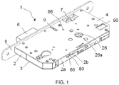
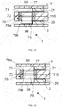
- the anti-panic lock 1 adapted to doors according to the invention comprises a case 2 delimited by a base 3, a cover 4, shown in Figure 1 , the base 3 and the cover 4 being arranged substantially parallel to each other, side walls 2a and a front 5 arranged substantially orthogonal to the base 3 and to the cover 4, a lever 6 that may be operated by a cylinder not shown in the figures, a latch 7 that may be operated by a first handle or a second handle not shown in the figures or the cylinder not shown in the figures, and a trigger element9, arranged between the lever 6 and the latch 7.
- the trigger element9 shown in Figures 2 to 4 , comprises a first part 9a that, in an initial open-door position not shown in the figures, projects out in relation to the front 5 towards the outside of the anti-panic lock 1, and a second part 9b that is arranged housed inside the case 2, the second part 9b including a groove 9c that cooperates with a projection 57 fixed to the base 3 to guide the movement of the trigger element9.
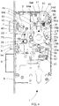
- the anti-panic lock 1 comprises means 100 for transmitting the movement associated to the cylinder or the corresponding handle towards the latch 7 or towards the lever 6, the transmission means 100 comprising a first pusher 20 adapted to be operated by the first handle, a second pusher 21 adapted to be operated by the second handle, and at least one slide member 110 adapted so that it may be moved, operated by the first pusher 20 or by the second pusher 21.
- the slide member 110 is arranged coupled to the lever 6, the slide member 110 including a groove 65, shown in Figures 2 , 3 , 10 and 12 , along which moves a connector member 55, shown in Figures 2 , 3 and 10 , inserted in the lever 6.
- the anti-panic lock 1 also includes a traction spring, not shown in the figures, one of the ends of which is arranged fixed to the base 3 of the case 2 and the other end is arranged fixed to one end of the slide member 110.
- the trigger element 9 keeps the slide member 110 locked.
- the trigger element 9 moves towards inside of the case 2, with the result that the first part 9a retracts and is housed in said case 2, and the second part 9b comes into contact with a switch 10, shown in Figure 2 , generating an electrical signal that indicates that the door is closed against the frame of the door and, at the same time, releases the slide member 110.
- the slide member 110 comprises a first cam 60, shown in detail in Figures 10 to 12 , which has a surface 60a that is arranged facing the second pusher 21 in a locked-door position, an intermediate cam 40, shown in detail in Figure 13 , which is arranged supported on a second surface 60b of the first cam 60 and a second cam 30, shown in detail in Figure 14 , which is arranged supported on the intermediate cam 40 and which includes a surface 30a, shown in Figure 11 , facing the first pusher 20 in the locked-door position, the cams 30,40,60 being arranged coupled to each other.
- the slide member 110 also includes guide means 80 that include a first corresponding groove 31,41,61 that collaborates with a substantially cylindrical guide member 53, shown in Figures 2 to 4 , 10 and 11 , fixed to the base 3 of the case 2 of the anti-panic lock 1, to guide the movement of the slide member 110 in relation to said base 3.
- the guide means 80 comprise in the first cam 60 a second groove 64 substantially parallel to the first groove 61, which collaborates with a substantially cylindrical guide member 54 fixed to the case 2, which also acts as a support for the first cam 60, and a projection 66, shown in Figures 1 to 3 , that collaborates with a groove 2b arranged on one of the walls 2a of the case 2 for the movement of the slide member 110 inside the case 2.
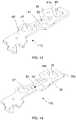
- the intermediate cam 40 comprises a projection 45, shown in Figures 2 , 4 , 10 , and 13 , that acts as a stopper when the lock is in the locked position, preventing said latch 7 from moving towards the inside of the case 2.
- both the intermediate cam 40 and the first cam 30 include on one end a respective housing 36,46 delimited by a surface 36b,46b, shown in Figures 13 and 14 , substantially sloping in relation to the direction of movement of the latch 7.
- the latch 7 comprises an internal part, not visible in the figures, housed inside the case 2, which includes a projection, not visible in the figures, which collaborates with the surface 36b,46b of the intermediate cam 40, with the result that the movement of the slide member 110 brings about the movement of the latch 7.
- the slide member 110 comprises three cams 30,40,60, in other embodiments not shown in the Figures, it may comprise two cams or even be made of a single piece.
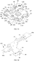
- the first pusher 20 shown in detail in Figures 5,6 , 8 and 11 , comprises a plate 20a that includes an arm 20b adapted to move the slide member 110 when the first handle is operated and an opening 20c with a rectangular cross-section, in which a follower 26 is coupled.
- the second pusher 21, shown in detail in Figures 5 and 11 comprises a second plate 21a that includes a second arm 21b adapted to move the slide member 110 when the second handle is operated, and an opening 21c with a rectangular cross-section, in which a follower 26 is coupled.
- the followers 26, shown in detail in Figure 10 each comprise a central part 26b with a substantially rectangular cross-section that is arranged inserted in the opening 20c, 21c of the corresponding pusher 20,21, and a longitudinal housing 26a in which is coupled a shaft of the corresponding handle, with the result that the followers 26 and, therefore, the respective pushers 20,21 rotate independently of each other.
- the anti-panic lock 1 comprises stoppers 29, shown in Figures 2 to 4 and 10 , fixed to the base 3, which collaborate with respective recesses 20f,21f in the respective pusher 20,21 to delimit the rotation of the pushers 20,21.
- the transmission means 100 also comprise an intermediate plate 22, shown in Figures 5 to 7 , which is arranged, in the embodiment described in the figures, fixed to the first pusher 20 by coupling pins 28, and a return spring 25 that is arranged housed inside the intermediate plate 22.
- the intermediate plate 22 includes a substantially concentric housing 22a in which is housed the return spring 25, preferably a torque spring, and a side opening 23 through which a first branch 25a, and a second branch 25b of the spring 25 project out, the ends 23a,23b of the opening 23 defining the limits of rotation of the handles.
- the intermediate plate 22 also has a central hole 22b in which the respective followers 26 coupled to the first pusher 20 and the second pusher 21 are partially coupled.
- the anti-panic lock 1 comprises a stopper 56, shown in Figures 2 and 4 , that is arranged inserted in the base 3 of the case 2 against which the second branch 25b acts permanently as a stopper.
- the first pusher 20 comprises a projection 20d, which extends towards the base 3, against which both branches 25a, 25b of the spring 25 act as stoppers in a position in which the handles are not operated, and against which only the first branch 25a acts as a stopper when the first handle has been operated.
- the second pusher 21 also comprises a projection 21d fixed to the second plate 21a, which extends towards the cover 4, against which both branches 25a,25b of the spring 25 act as stoppers in a position in which the handles are not operated, and against which only the first branch 25a acts as a stopper when the second handle has been operated.
- the projection 20d of the first pusher 20 and the projection 21d of second pusher 21 are arranged substantially aligned.
- the anti-panic lock 1 of the invention comprises clutch means 90 that couple both pushers 20,21 for the simultaneous rotation of both handles regardless of which handle is operated by the user.
- the clutch means 90 shown in Figures 2 to 4 , comprise a support 91 fixed to the base 3, a motor 92 supported by the support 91, an endless screw 93 coupled to the motor 92, an actuator 94 fixed at one end in a pivoting manner to the support 91 and which includes a contact member 94b that is in contact with the endless screw 93, and a clutch 95, shown in Figures 4 and 6 , that couples the pushers 20,21 when operated by the actuator 94.
- the actuator 94 is made of flexible material.
- the contact member 94 has a substantially orthogonal cross-section, its width being smaller than the distance between two consecutive threads of the endless screw 93.
- the actuator 94 shown in Figures 2 and 4 , comprises a base 94d that includes the contact surface 94c and which is arranged supported on the base 3 of the case 2, a first projection 94a that is fixed substantially orthogonal to the base 94d of the actuator 94, it being inserted in a hole of said base 94d, by which the actuator 94 is fixed in a pivoting manner to the support 91, and a second projection 94f from which the contact member 94b is arranged substantially orthogonal to the endless screw 93.
- the clutch 95 is housed in the intermediate plate 22 of the transmission means 100, comprising a substantially rectangular first part 95a, and a second part 95b with a substantially rectangular cross-section, and a greater width than the first part 95a. Additionally, the intermediate plate 22, shown in Figures 6 and 7 , includes a cavity 24 that has a first part 24a inside which is housed the second part 95b of the clutch 95, and a second part 24b connected to the first part 24a and the exterior, with a smaller width than the first part 24a, inside which is housed the first part 95a of the clutch 95.
- the clutch 95 includes in the second part 95 a housing 95c in which is housed a spring 97.
- the second pusher 21 includes, on the end opposite the arm 21b, grooves 21e shown in Figure 5 where stoppers 27 are arranged inserted, arranged facing the first pusher 20 and which delimit a housing 27b, shown in Figure 6 , between them.
- both pushers 20,21 are declutched, the motor 91 is not operating, and the actuator 94 acts on the clutch 95, in particular on the first part 95a, with the result that the clutch 95 compresses the spring 96, being housed entirely in the cavity 24 of the intermediate plate 22, each pusher 20,21 being capable of rotating independently in relation to the other pusher 21,20, given that the respective projection 27 of the second pusher 21 acts as a stopper, preventing the clutch 95 from expanding outside the cavity 24. Subsequently, the respective pusher 20,21 returns to the initial position by the return spring 25.
- the endless screw 93 rotates in an anti-clockwise direction, with the result that the contact member 94b of the actuator 94 is moved by the endless screw 93 in a direction towards the motor 91, with the result that both pushers 20,21 are coupled to each other, rotating jointly when either of the two handles is operated.
- the second part 95b of the clutch 95 acts as a stopper against the first part 24a of the cavity 24 of the intermediate plate 22, with the result that the first part 95a is partially housed in the housing 27b delimited by the stoppers 27, with the result that both pushers 20,21 are clutched together.
- the anti-panic release means 70 shown in detail in Figures 15 and 16 , comprise a sleeve 71 that is arranged inserted in the slide member 110, for which purpose the respective cams 30,40,60 comprised in the slide member 110 respectively include a hole 37,45,67 in which the sleeve 71 is inserted fixed.
- the anti-panic release means 70 also comprise a substantially cylindrical positioning member 75, inserted in a movable manner in the sleeve 71.
- the sleeve 71 includes an inner ring-shaped groove 72 in which is housed an elastic means 77, and the positioning member 75 also comprises a first outer groove 76b and a second outer groove 76a both of them ring-shaped grooves, separated from each other by a certain distance.
- the elastic means 77 preferably includes an elastic seal. In other embodiments the elastic means 77 may include elastic washers, a spring, ring seals, etc.
- the positioning member 75 is arranged inserted in the sleeve 71 with the result that the elastic seal 77 inserted in the inner groove 72 of the sleeve 71 is housed in the first outer groove 76b of said positioning member 75, the positioning member 75 projecting out in relation to the slide member 110, and in particular in relation to the free surface 60a of the first cam 60, being supported on the cover 4 of the case 2 of the anti-panic lock 1.
- the positioning member 75 is arranged inserted in the sleeve 71 with the result that the elastic seal 77, inserted in the inner groove 72 of the sleeve 71 is housed tightly in the second outer groove 76a of the positioning member 75, the positioning member 75 projecting out in relation to the slide member 110, in particular in relation to the free surface 30a of the second cam 30, it being supported on the base 3 of the case 2 of the anti-panic lock 1.
- both the cover 4 and the base 3 of the case 2 respectively comprise a hole 96, shown in Figures 1 , 15 and 16 , arranged concentric to each other and to the positioning member 75, with the result that by introducing a suitable tool through the corresponding hole 96, the positioning member 75 may be moved from one position to another, thereby allowing the user to change, quickly and easily from the outside of the anti-panic lock 1, the configuration of said anti-panic lock 1 in order to obtain an anti-panic lock 1 that is unlocked when the first handle is operated or is unlocked when the second handle is operated.
Description
- This invention relates to anti-panic locks adapted to doors.
- Known anti-panic locks adapted to doors comprise a lever by which the door is locked, the lever being operable by a cylinder, and a latch that may be operated by an external handle or by the cylinder. The electro-mechanical lock also comprises coupling means that convert the rotational movement of the handle into a movement of the latch.
- In addition, there are known anti-panic locks the object of which is to release the door quickly in an emergency situation. This type of safety device allows the user to open the door quickly from one of the sides when the door is locked, preventing opening from the other side. Locks of this type including different means for the rapid release of the lever are described in the following patent documents:
EP16969525A1 ES2048616B1 ES2066673A1 ES2211277B1 -
US2008/0066505A1 also describes an electromechanical anti-panic lock wherein it is possible to choose from which side of the door the anti-panic release means are operated. The lock comprises first and second plates, each of which is coupled to a corresponding handle, a first cam adapted to act on the latch, and a second cam adapted to act on the lever, the plate connected to the second cam determining which handle operates the anti-panic release means. - Document
DE20307120U1 discloses an anti-panic locks adapted to doors according to the preamble ofclaim 1. - The object of the invention is to provide an anti-panic lock adapted to doors as described in the claims.
- The anti-panic lock of the invention comprises at least one lever that may be operated by a cylinder, a latch that may be operated by a first handle arranged on one side of the door or by a second handle arranged on the opposite side of the door, and means for transmitting the movement associated to the cylinder or the corresponding handle towards the latch or towards the lever, the transmission means comprising a first pusher that rotates when operated by the first handle, a second pusher that rotates when operated by the second handle, and at least one slide member that moves when operated by the first pusher or by the second pusher.
- The anti-panic lock also comprises anti-panic release means that, when operated by one of the two handles, act on the transmission means and release the lever.
- The anti-panic release means are arranged inserted in the slide member projecting out from one of the surfaces of said slide member, with the result that only the pusher that is arranged facing the surface from which the anti-panic release means project out operates said anti-panic release means, releasing the lever.
- Thus, depending on which surface of the slide member the release means project out from, either the first pusher operated by the first handle or the second pusher operated by the second handle shall operate said release means.
- The anti-panic release means comprise a sleeve that is arranged inserted in the slide member and a positioning member inserted in a movable manner in the sleeve.
- The sleeve includes an internal groove in which is housed an elastic means, and the positioning member comprises an external first groove and an external second groove, with the result that the elastic means inserted in the inner groove is housed tightly and selectively in one of the external grooves.
- An optimised anti-panic lock is thus obtained and which can be used in both directions, in other words the anti-panic lock may be unlocked from one side of the door by operating the first handle, or from the opposite side of the door by operating the second handle, as a result of which it is only necessary to change which surface of the slide member the release means project out from.
- These and other advantages and characteristics of the invention will be made evident in the light of the drawings and the detailed description thereof.
-
-
Figure 1 shows a perspective view of an anti-panic lock according to the invention, in a position wherein the door is closed or locked. -
Figure 2 is a ground view of the anti-panic lock shown inFigure 1 , without a cover. -
Figure 3 is a perspective view of the anti-panic lock shown inFigure 1 , without a cover and with exploded anti-panic release means. -
Figure 4 is a ground view of the anti-panic lock shown inFigure 1 , wherein some elements have been hidden to aid comprehension. -
Figure 5 is a partial perspective view of transmission means comprised in the anti-panic lock shown inFigure 1 . -
Figure 6 is a partial perspective view of the transmission means shown inFigure 5 , without a second pusher. -
Figure 7 is a view in perspective of an intermediate plate of the transmission means shown inFigure 5 . -
Figure 8 is a view in perspective of a first pusher of the transmission means shown inFigure 5 . -
Figure 9 is a view of a unit of followers comprised in the anti-panic lock shown inFigure 1 . -
Figure 10 is a view in perspective of transmission means and anti-panic release means shown inFigure 1 . -
Figure 11 is a sectional view in perspective of transmission means and anti-panic release means shown inFigure 1 . -
Figure 12 is a view in perspective of a first cam of a slide member comprised in the anti-panic lock shown inFigure 1 . -
Figure 13 is a view in perspective of an intermediate cam of a slide member comprised in the anti-panic lock shown inFigure 1 . -
Figure 14 is a view in perspective of a second cam of a slide member comprised in the anti-panic lock shown inFigure 1 . -
Figure 15 is a sectional schematic view of the anti-panic lock shown inFigure 1 , with anti-panic release means in a second position. -
Figure 16 is a sectional schematic view of the anti-panic lock shown inFigure 1 , with anti-panic release means in a first position. - The
anti-panic lock 1 adapted to doors according to the invention, shown inFigures 1 to 4 , comprises acase 2 delimited by abase 3, a cover 4, shown inFigure 1 , thebase 3 and the cover 4 being arranged substantially parallel to each other,side walls 2a and afront 5 arranged substantially orthogonal to thebase 3 and to the cover 4, alever 6 that may be operated by a cylinder not shown in the figures, alatch 7 that may be operated by a first handle or a second handle not shown in the figures or the cylinder not shown in the figures, and a trigger element9, arranged between thelever 6 and thelatch 7. - The trigger element9, shown in
Figures 2 to 4 , comprises afirst part 9a that, in an initial open-door position not shown in the figures, projects out in relation to thefront 5 towards the outside of theanti-panic lock 1, and asecond part 9b that is arranged housed inside thecase 2, thesecond part 9b including agroove 9c that cooperates with aprojection 57 fixed to thebase 3 to guide the movement of the trigger element9. - The
anti-panic lock 1 comprises means 100 for transmitting the movement associated to the cylinder or the corresponding handle towards thelatch 7 or towards thelever 6, the transmission means 100 comprising afirst pusher 20 adapted to be operated by the first handle, asecond pusher 21 adapted to be operated by the second handle, and at least oneslide member 110 adapted so that it may be moved, operated by thefirst pusher 20 or by thesecond pusher 21. - The
slide member 110 is arranged coupled to thelever 6, theslide member 110 including agroove 65, shown inFigures 2 ,3 ,10 and12 , along which moves aconnector member 55, shown inFigures 2 ,3 and10 , inserted in thelever 6. - The
anti-panic lock 1 also includes a traction spring, not shown in the figures, one of the ends of which is arranged fixed to thebase 3 of thecase 2 and the other end is arranged fixed to one end of theslide member 110. - In an initial position, wherein the
anti-panic lock 1 has not been operated, thetrigger element 9 keeps theslide member 110 locked. At the time that the door closes, thetrigger element 9 moves towards inside of thecase 2, with the result that thefirst part 9a retracts and is housed in saidcase 2, and thesecond part 9b comes into contact with aswitch 10, shown inFigure 2 , generating an electrical signal that indicates that the door is closed against the frame of the door and, at the same time, releases theslide member 110. When theslide member 110 is released, the traction spring to which is arranged fixed one end of theslide member 110 attracts theslide member 110, with the result that the movement of saidslide member 110 causes the operation of thelever 6, which moves and projects out in relation to thecase 2 of theanti-panic lock 1, thereby locking the door. - The
slide member 110 comprises afirst cam 60, shown in detail inFigures 10 to 12 , which has asurface 60a that is arranged facing thesecond pusher 21 in a locked-door position, anintermediate cam 40, shown in detail inFigure 13 , which is arranged supported on asecond surface 60b of thefirst cam 60 and asecond cam 30, shown in detail inFigure 14 , which is arranged supported on theintermediate cam 40 and which includes asurface 30a, shown inFigure 11 , facing thefirst pusher 20 in the locked-door position, thecams - The
slide member 110 also includes guide means 80 that include a firstcorresponding groove cylindrical guide member 53, shown inFigures 2 to 4 ,10 and11 , fixed to thebase 3 of thecase 2 of theanti-panic lock 1, to guide the movement of theslide member 110 in relation to saidbase 3. In addition, the guide means 80 comprise in thefirst cam 60 asecond groove 64 substantially parallel to thefirst groove 61, which collaborates with a substantiallycylindrical guide member 54 fixed to thecase 2, which also acts as a support for thefirst cam 60, and aprojection 66, shown inFigures 1 to 3 , that collaborates with agroove 2b arranged on one of thewalls 2a of thecase 2 for the movement of theslide member 110 inside thecase 2. - In addition, the
intermediate cam 40 comprises aprojection 45, shown inFigures 2 ,4 ,10 , and13 , that acts as a stopper when the lock is in the locked position, preventing saidlatch 7 from moving towards the inside of thecase 2. Additionally, both theintermediate cam 40 and thefirst cam 30 include on one end arespective housing surface Figures 13 and 14 , substantially sloping in relation to the direction of movement of thelatch 7. - Additionally the
latch 7 comprises an internal part, not visible in the figures, housed inside thecase 2, which includes a projection, not visible in the figures, which collaborates with thesurface intermediate cam 40, with the result that the movement of theslide member 110 brings about the movement of thelatch 7. - Although in the embodiment shown in the Figures, the
slide member 110 comprises threecams - Furthermore, the
first pusher 20, shown in detail inFigures 5,6 ,8 and11 , comprises aplate 20a that includes anarm 20b adapted to move theslide member 110 when the first handle is operated and an opening 20c with a rectangular cross-section, in which afollower 26 is coupled. - In addition, the
second pusher 21, shown in detail inFigures 5 and11 , comprises asecond plate 21a that includes asecond arm 21b adapted to move theslide member 110 when the second handle is operated, and an opening 21c with a rectangular cross-section, in which afollower 26 is coupled. Thefollowers 26, shown in detail inFigure 10 , each comprise acentral part 26b with a substantially rectangular cross-section that is arranged inserted in the opening 20c, 21c of thecorresponding pusher longitudinal housing 26a in which is coupled a shaft of the corresponding handle, with the result that thefollowers 26 and, therefore, therespective pushers - The
anti-panic lock 1 comprisesstoppers 29, shown inFigures 2 to 4 and10 , fixed to thebase 3, which collaborate withrespective recesses respective pusher pushers - The transmission means 100 also comprise an
intermediate plate 22, shown inFigures 5 to 7 , which is arranged, in the embodiment described in the figures, fixed to thefirst pusher 20 bycoupling pins 28, and areturn spring 25 that is arranged housed inside theintermediate plate 22. For this purpose theintermediate plate 22 includes a substantiallyconcentric housing 22a in which is housed thereturn spring 25, preferably a torque spring, and a side opening 23 through which afirst branch 25a, and asecond branch 25b of thespring 25 project out, theends opening 23 defining the limits of rotation of the handles. Theintermediate plate 22 also has acentral hole 22b in which therespective followers 26 coupled to thefirst pusher 20 and thesecond pusher 21 are partially coupled. - The
anti-panic lock 1 comprises astopper 56, shown inFigures 2 and4 , that is arranged inserted in thebase 3 of thecase 2 against which thesecond branch 25b acts permanently as a stopper. In addition, thefirst pusher 20 comprises aprojection 20d, which extends towards thebase 3, against which bothbranches spring 25 act as stoppers in a position in which the handles are not operated, and against which only thefirst branch 25a acts as a stopper when the first handle has been operated. Additionally, thesecond pusher 21 also comprises aprojection 21d fixed to thesecond plate 21a, which extends towards the cover 4, against which bothbranches spring 25 act as stoppers in a position in which the handles are not operated, and against which only thefirst branch 25a acts as a stopper when the second handle has been operated. Thus, in a position in which the handles are not operated, theprojection 20d of thefirst pusher 20 and theprojection 21d ofsecond pusher 21 are arranged substantially aligned. - In addition, the
anti-panic lock 1 of the invention comprises clutch means 90 that couple bothpushers Figures 2 to 4 , comprise asupport 91 fixed to thebase 3, amotor 92 supported by thesupport 91, anendless screw 93 coupled to themotor 92, anactuator 94 fixed at one end in a pivoting manner to thesupport 91 and which includes acontact member 94b that is in contact with theendless screw 93, and a clutch 95, shown inFigures 4 and6 , that couples thepushers actuator 94. Theactuator 94 is made of flexible material. - The
contact member 94 has a substantially orthogonal cross-section, its width being smaller than the distance between two consecutive threads of theendless screw 93. - The
actuator 94, shown inFigures 2 and4 , comprises abase 94d that includes thecontact surface 94c and which is arranged supported on thebase 3 of thecase 2, afirst projection 94a that is fixed substantially orthogonal to thebase 94d of theactuator 94, it being inserted in a hole of saidbase 94d, by which theactuator 94 is fixed in a pivoting manner to thesupport 91, and asecond projection 94f from which thecontact member 94b is arranged substantially orthogonal to theendless screw 93. - The clutch 95 is housed in the
intermediate plate 22 of the transmission means 100, comprising a substantially rectangularfirst part 95a, and asecond part 95b with a substantially rectangular cross-section, and a greater width than thefirst part 95a. Additionally, theintermediate plate 22, shown inFigures 6 and7 , includes acavity 24 that has afirst part 24a inside which is housed thesecond part 95b of the clutch 95, and asecond part 24b connected to thefirst part 24a and the exterior, with a smaller width than thefirst part 24a, inside which is housed thefirst part 95a of the clutch 95. The clutch 95 includes in thesecond part 95 ahousing 95c in which is housed aspring 97. - Furthermore, the
second pusher 21 includes, on the end opposite thearm 21b,grooves 21e shown inFigure 5 wherestoppers 27 are arranged inserted, arranged facing thefirst pusher 20 and which delimit ahousing 27b, shown inFigure 6 , between them. - Thus, in an initial position of the
anti-panic lock 1, bothpushers motor 91 is not operating, and the actuator 94 acts on the clutch 95, in particular on thefirst part 95a, with the result that the clutch 95 compresses thespring 96, being housed entirely in thecavity 24 of theintermediate plate 22, eachpusher other pusher respective projection 27 of thesecond pusher 21 acts as a stopper, preventing the clutch 95 from expanding outside thecavity 24. Subsequently, therespective pusher return spring 25. - When the
motor 91 receives a certain electrical impulse theendless screw 93 rotates in an anti-clockwise direction, with the result that thecontact member 94b of theactuator 94 is moved by theendless screw 93 in a direction towards themotor 91, with the result that bothpushers second part 95b of the clutch 95 acts as a stopper against thefirst part 24a of thecavity 24 of theintermediate plate 22, with the result that thefirst part 95a is partially housed in thehousing 27b delimited by thestoppers 27, with the result that bothpushers - From this position, when the
motor 91 receives an electrical impulse contrary to the initial one, theendless screw 93 rotates in a clockwise direction, with the result that theend 94b of theactuator 94 is moved by theendless screw 93 in a direction towards the clutch 95, with the result that theactuator 94 once more keeps the clutch 95 pressed down inside thecavity 24, thus keeping thepushers - In addition, the anti-panic release means 70, shown in detail in
Figures 15 and 16 , comprise asleeve 71 that is arranged inserted in theslide member 110, for which purpose therespective cams slide member 110 respectively include ahole sleeve 71 is inserted fixed. The anti-panic release means 70 also comprise a substantiallycylindrical positioning member 75, inserted in a movable manner in thesleeve 71. Thesleeve 71 includes an inner ring-shapedgroove 72 in which is housed anelastic means 77, and the positioningmember 75 also comprises a firstouter groove 76b and a secondouter groove 76a both of them ring-shaped grooves, separated from each other by a certain distance. The elastic means 77 preferably includes an elastic seal. In other embodiments the elastic means 77 may include elastic washers, a spring, ring seals, etc. - When the anti-panic release means 70 are arranged in a first position, shown in
Figure 16 , the positioningmember 75 is arranged inserted in thesleeve 71 with the result that theelastic seal 77 inserted in theinner groove 72 of thesleeve 71 is housed in the firstouter groove 76b of saidpositioning member 75, the positioningmember 75 projecting out in relation to theslide member 110, and in particular in relation to thefree surface 60a of thefirst cam 60, being supported on the cover 4 of thecase 2 of theanti-panic lock 1. As a result, starting from a position in which the door is closed and locked by thelever 6, thepushers anti-panic lock 1 quickly, as when said second handle is operated, thesecond pusher 21 rotates and, facing thesurface 60a of thefirst cam 60, as shown inFigure 11 , acts as a stopper against the part of the positioningmember 75 that projects out, thereby moving theslide member 110. The movement of theslide member 110 causes the movement of thelever 6 and thelatch 7 towards the inside of thecase 2, enabling the opening of the door. If the user operated the first handle, the rotation of thefirst pusher 20 would not move theslide member 110, and thelever 6 therefore would continue to lock the door. - In contrast, when the anti-panic release means 70 are arranged in a second position, shown in
Figure 15 , the positioningmember 75 is arranged inserted in thesleeve 71 with the result that theelastic seal 77, inserted in theinner groove 72 of thesleeve 71 is housed tightly in the secondouter groove 76a of the positioningmember 75, the positioningmember 75 projecting out in relation to theslide member 110, in particular in relation to thefree surface 30a of thesecond cam 30, it being supported on thebase 3 of thecase 2 of theanti-panic lock 1. As a result, starting from a position wherein the door is closed and locked by thelever 6 and thepushers anti-panic lock 1 quickly, as when said first handle is operated, thefirst pusher 20 rotates and, facing thesurface 30a of thefirst cam 30, as shown inFigure 11 , acts as a stopper against the part of the positioningmember 75 that projects out, thereby moving theslide member 110. The movement of theslide member 110 causes the movement of thelever 6 and thelatch 7 towards the inside of thecase 2, enabling the opening of the door. - Finally, both the cover 4 and the
base 3 of thecase 2 respectively comprise ahole 96, shown inFigures 1 ,15 and 16 , arranged concentric to each other and to the positioningmember 75, with the result that by introducing a suitable tool through the correspondinghole 96, the positioningmember 75 may be moved from one position to another, thereby allowing the user to change, quickly and easily from the outside of theanti-panic lock 1, the configuration of saidanti-panic lock 1 in order to obtain ananti-panic lock 1 that is unlocked when the first handle is operated or is unlocked when the second handle is operated.
Claims (12)
- Anti-panic lock adapted to doors that comprises at least one lever (6) that may be operated by a cylinder, a latch (7) that may be operated by a first handle arranged on one side of the door or by a second handle arranged on the opposite side of the door, means (100) for transmitting the movement associated to the cylinder or the corresponding handle towards the latch (7) or towards the lever (6), the transmission means (100) comprising a first pusher (20) adapted to rotate when operated by the first handle, a second pusher (21) adapted to rotate when operated by the second handle, and at least one slide member (110) that moves when it is operated by the first pusher (20) or by the second pusher (21), and anti-panic release means (70) that, when operated by the handles, act on the transmission means (100) and release the lever (6), the anti-panic release means (70) being arranged inserted in the slide member (110), projecting out from one of the surfaces (30a,60a) corresponding to the slide member (110), with the result that only the pusher (20,21) that is arranged facing the surface (30a,60a) from which the anti-panic release means (70) project operates the anti-panic release means (90), wherein the anti-panic release means (70) comprise a sleeve (71) that is arranged inserted in the slide member (110), and a positioning member (75) inserted in a movable manner in the sleeve (71) characterised in that the sleeve (71) includes an internal groove (72) in which is housed an elastic means (77), and the positioning member (75) comprises an external first groove (76b) and an external second groove (76a), with the result that the elastic means (77) inserted in the inner groove (72) is housed tightly and selectively in one of the external grooves (76a,76b).
- Anti-panic lock according to the preceding claim, wherein the anti-panic release means (70) are arranged inserted in the slide member (110) selectively, in a first position, in which the anti-panic lock (1) is unlocked when the first handle is turned, or in a second position, in which the anti-panic lock (1) is unlocked when the second handle is turned.
- Anti-panic lock according to any of the preceding claims, wherein it comprises a cover (4) and a base (3), which are respectively included in a hole (96), arranged concentric to each other and to the anti-panic release means (70), said anti-panic release means (70) being operated through the holes (96).
- Anti-panic lock according to any of the preceding claims, wherein the first pusher (20) and the second pusher (21) respectively comprise arms (20b,21b) that operate the slide member (110).
- Anti-panic lock according to any of the preceding claims, wherein the first pusher (20) and the second pusher (21) respectively comprise openings (20c, 21c) in each of which a follower (26) is coupled jointly for the coupling of the corresponding handle.
- Anti-panic lock according to any of the preceding claims, wherein the transmission means (100) comprise an intermediate plate (22), arranged between the first pusher (20) and the second pusher (21), which houses a spring (25) returning the first pusher (20) or the second pusher (21) to a rest position.
- Anti-panic lock according to the preceding claim, wherein the intermediate plate (22) comprises an opening (23) through which the ends of the return spring (25) project out, the ends (23a,23b) of the opening (23) delimiting the limits of rotation of the first pusher (20) or the second pusher (21).
- Anti-panic lock according to the preceding claim, wherein the intermediate plate (22) is arranged fixed to the first pusher (20) or to the second pusher (21).
- Anti-panic lock according to any of the preceding claims, wherein the slide member (110) is arranged coupled to the latch (7), moving it towards the inside of a case (2) of the anti-panic lock (1), when one of the handles is operated.
- Anti-panic lock according to any of the preceding claims, wherein the slide member (110) includes a groove (65) through which is arranged coupled a projection (55) inserted in the lever (6).
- Anti-panic lock according to any of the preceding claims, wherein the slide member (110) comprises a first cam (60) that is arranged facing one of the pushers (20,21), an intermediate cam (40) that is arranged supported on the first cam (40) and a second cam (30) that is supported on the intermediate cam (40) and facing one of the pushers (21,20), the cams (30,40,60) being arranged couple to each other.
- Anti-panic lock according to the preceding claim, wherein the cams (30,40,60) include guide means (80) that comprise at least one first groove (31,41,61) that collaborates with a corresponding guide member (51) fixed to the base (3) in order to guide the movement of the slide member (110).
Priority Applications (1)
| Application Number | Priority Date | Filing Date | Title |
|---|---|---|---|
| PL11382118T PL2385199T3 (en) | 2010-05-04 | 2011-04-18 | Anti-panic lock adapted to doors |
Applications Claiming Priority (1)
| Application Number | Priority Date | Filing Date | Title |
|---|---|---|---|
| ES201030423U ES1073001Y (en) | 2010-05-04 | 2010-05-04 | ANTI-PANIC DOOR ADAPTED LOCK |
Publications (3)
| Publication Number | Publication Date |
|---|---|
| EP2385199A2 EP2385199A2 (en) | 2011-11-09 |
| EP2385199A3 EP2385199A3 (en) | 2015-04-08 |
| EP2385199B1 true EP2385199B1 (en) | 2017-10-18 |
Family
ID=42824844
Family Applications (1)
| Application Number | Title | Priority Date | Filing Date |
|---|---|---|---|
| EP11382118.5A Active EP2385199B1 (en) | 2010-05-04 | 2011-04-18 | Anti-panic lock adapted to doors |
Country Status (3)
| Country | Link |
|---|---|
| EP (1) | EP2385199B1 (en) |
| ES (1) | ES1073001Y (en) |
| PL (1) | PL2385199T3 (en) |
Cited By (1)
| Publication number | Priority date | Publication date | Assignee | Title |
|---|---|---|---|---|
| US10526816B2 (en) * | 2015-11-27 | 2020-01-07 | Tong Lung Metal Industry Co., Ltd. | Door lock having locking mechanism |
Families Citing this family (5)
| Publication number | Priority date | Publication date | Assignee | Title |
|---|---|---|---|---|
| EP2754788A1 (en) * | 2013-01-11 | 2014-07-16 | BKS GmbH | Lock |
| FR3045091B1 (en) * | 2015-12-11 | 2019-06-14 | Dubois Industries | LOCK OPERABLE BY A FIRST ORDER SUCH AS AN ANTI-PANIC BAR AND BY A SECOND KEY CONTROL |
| CN208329905U (en) * | 2018-02-26 | 2019-01-04 | 一诺电器有限公司 | A kind of smart lock back locking structure |
| SE543452C2 (en) * | 2018-08-23 | 2021-02-23 | Stendals El Ab | Locking device with a movable actuator for selecting an active side of a door, accessible from a side facing away from the locking bolt |
| IT201900009867A1 (en) * | 2019-06-24 | 2020-12-24 | Pba S P A | LOCK STRUCTURE |
Family Cites Families (9)
| Publication number | Priority date | Publication date | Assignee | Title |
|---|---|---|---|---|
| ES2048616B1 (en) | 1991-06-05 | 1997-10-16 | Cerrajera Ind | SECURITY DEVICE FOR LATCH LOCKS. |
| ES2066673B1 (en) * | 1992-07-20 | 1996-10-16 | Talleres Escoriaza Sa | PERFECTED ANTI-PANIC LOCK. |
| ES2211277B1 (en) | 2002-04-10 | 2005-10-01 | La Industrial Cerrajera, S.A. | SECURITY LOCK WITH DOUBLE CONTROL OF THE PICAPORTE AND ANTIPANIC FUNCTION. |
| NL1022523C2 (en) * | 2003-01-30 | 2004-08-16 | Lips Nederland B V | Lock assembly for houses front door, has coupling plates provided to bring sliding plate in and out of coupled condition between dead bolt and inner lever handle that is coupled with operation plate for retracting latch |
| DE20307120U1 (en) * | 2003-04-30 | 2003-07-10 | Gretsch Unitas Gmbh | Lock, releasable using coupling piece connectable to handle nut half section |
| US7812935B2 (en) | 2005-12-23 | 2010-10-12 | Ingenia Holdings Limited | Optical authentication |
| US7926315B2 (en) | 2006-09-19 | 2011-04-19 | Imperial USA, Ltd | Lock assembly with anti-panic feature and associated method |
| WO2009087464A1 (en) * | 2007-12-26 | 2009-07-16 | Goldtec Migun 2005 Ltd. | Mortise lock |
| DE202009008432U1 (en) * | 2009-06-15 | 2009-08-20 | Bks Gmbh | lock |
-
2010
- 2010-05-04 ES ES201030423U patent/ES1073001Y/en not_active Expired - Fee Related
-
2011
- 2011-04-18 PL PL11382118T patent/PL2385199T3/en unknown
- 2011-04-18 EP EP11382118.5A patent/EP2385199B1/en active Active
Non-Patent Citations (1)
| Title |
|---|
| None * |
Cited By (1)
| Publication number | Priority date | Publication date | Assignee | Title |
|---|---|---|---|---|
| US10526816B2 (en) * | 2015-11-27 | 2020-01-07 | Tong Lung Metal Industry Co., Ltd. | Door lock having locking mechanism |
Also Published As
| Publication number | Publication date |
|---|---|
| PL2385199T3 (en) | 2018-03-30 |
| EP2385199A2 (en) | 2011-11-09 |
| ES1073001U (en) | 2010-10-19 |
| ES1073001Y (en) | 2011-02-07 |
| EP2385199A3 (en) | 2015-04-08 |
Similar Documents
| Publication | Publication Date | Title |
|---|---|---|
| EP2385199B1 (en) | Anti-panic lock adapted to doors | |
| EP2570574B1 (en) | Solenoid operated electromechanical lock | |
| US10563434B2 (en) | Locking unit for a motor vehicle | |
| US10662674B2 (en) | Structures of electronic lock | |
| RU2007139009A (en) | SIDE DOOR VEHICLE | |
| US20140191516A1 (en) | Side mounted privacy lock for a residential door | |
| JP5385294B2 (en) | Latch actuator and latch using the same | |
| EP3156571B1 (en) | Lock with actuation system of the latch bolt | |
| CN109790725B (en) | Handle device | |
| US5896764A (en) | Lock adapted to be accommodated within the thickness of an opening panel | |
| GB2413153A (en) | Latch assembly with lockable sliding actuator | |
| KR200423328Y1 (en) | The device of panic motise and working methode | |
| EP2385198B1 (en) | Electromechanical lock adapted to doors | |
| GB2494620A (en) | Thumb turn mechanism for a cylinder lock | |
| CN112823232A (en) | Latch lock | |
| US20090107194A1 (en) | Cylinder lock and unlocking device comprising thereof | |
| KR101595853B1 (en) | Door Lock Device Having Clutch Structure | |
| WO2003091518A8 (en) | A combination lock | |
| US11066848B2 (en) | Push to lock and unlock door lock | |
| CN112955618B (en) | Lock head for driving mechanism | |
| EP3771790B1 (en) | Lock | |
| TWI663319B (en) | Lock with an emergency unlocking feature | |
| JP6100125B2 (en) | Anti-panic automatic lock | |
| JP5064170B2 (en) | Cylinder lock and unlocking device having the same | |
| RU2295019C2 (en) | Code lock with serial input mechanism |
Legal Events
| Date | Code | Title | Description |
|---|---|---|---|
| AK | Designated contracting states |
Kind code of ref document: A2 Designated state(s): AL AT BE BG CH CY CZ DE DK EE ES FI FR GB GR HR HU IE IS IT LI LT LU LV MC MK MT NL NO PL PT RO RS SE SI SK SM TR |
|
| AX | Request for extension of the european patent |
Extension state: BA ME |
|
| PUAI | Public reference made under article 153(3) epc to a published international application that has entered the european phase |
Free format text: ORIGINAL CODE: 0009012 |
|
| PUAL | Search report despatched |
Free format text: ORIGINAL CODE: 0009013 |
|
| AK | Designated contracting states |
Kind code of ref document: A3 Designated state(s): AL AT BE BG CH CY CZ DE DK EE ES FI FR GB GR HR HU IE IS IT LI LT LU LV MC MK MT NL NO PL PT RO RS SE SI SK SM TR |
|
| AX | Request for extension of the european patent |
Extension state: BA ME |
|
| RIC1 | Information provided on ipc code assigned before grant |
Ipc: E05B 65/10 20060101AFI20150305BHEP Ipc: E05B 59/00 20060101ALI20150305BHEP Ipc: E05B 63/16 20060101ALI20150305BHEP Ipc: E05B 47/00 20060101ALI20150305BHEP Ipc: E05B 63/20 20060101ALI20150305BHEP |
|
| 17P | Request for examination filed |
Effective date: 20151008 |
|
| RBV | Designated contracting states (corrected) |
Designated state(s): AL AT BE BG CH CY CZ DE DK EE ES FI FR GB GR HR HU IE IS IT LI LT LU LV MC MK MT NL NO PL PT RO RS SE SI SK SM TR |
|
| GRAP | Despatch of communication of intention to grant a patent |
Free format text: ORIGINAL CODE: EPIDOSNIGR1 |
|
| INTG | Intention to grant announced |
Effective date: 20170518 |
|
| GRAS | Grant fee paid |
Free format text: ORIGINAL CODE: EPIDOSNIGR3 |
|
| GRAA | (expected) grant |
Free format text: ORIGINAL CODE: 0009210 |
|
| AK | Designated contracting states |
Kind code of ref document: B1 Designated state(s): AL AT BE BG CH CY CZ DE DK EE ES FI FR GB GR HR HU IE IS IT LI LT LU LV MC MK MT NL NO PL PT RO RS SE SI SK SM TR |
|
| REG | Reference to a national code |
Ref country code: GB Ref legal event code: FG4D |
|
| REG | Reference to a national code |
Ref country code: CH Ref legal event code: EP |
|
| REG | Reference to a national code |
Ref country code: AT Ref legal event code: REF Ref document number: 938098 Country of ref document: AT Kind code of ref document: T Effective date: 20171115 Ref country code: IE Ref legal event code: FG4D |
|
| REG | Reference to a national code |
Ref country code: DE Ref legal event code: R096 Ref document number: 602011042474 Country of ref document: DE |
|
| REG | Reference to a national code |
Ref country code: NL Ref legal event code: MP Effective date: 20171018 |
|
| REG | Reference to a national code |
Ref country code: LT Ref legal event code: MG4D |
|
| REG | Reference to a national code |
Ref country code: AT Ref legal event code: MK05 Ref document number: 938098 Country of ref document: AT Kind code of ref document: T Effective date: 20171018 |
|
| PG25 | Lapsed in a contracting state [announced via postgrant information from national office to epo] |
Ref country code: NL Free format text: LAPSE BECAUSE OF FAILURE TO SUBMIT A TRANSLATION OF THE DESCRIPTION OR TO PAY THE FEE WITHIN THE PRESCRIBED TIME-LIMIT Effective date: 20171018 |
|
| REG | Reference to a national code |
Ref country code: FR Ref legal event code: PLFP Year of fee payment: 8 |
|
| PG25 | Lapsed in a contracting state [announced via postgrant information from national office to epo] |
Ref country code: SE Free format text: LAPSE BECAUSE OF FAILURE TO SUBMIT A TRANSLATION OF THE DESCRIPTION OR TO PAY THE FEE WITHIN THE PRESCRIBED TIME-LIMIT Effective date: 20171018 Ref country code: FI Free format text: LAPSE BECAUSE OF FAILURE TO SUBMIT A TRANSLATION OF THE DESCRIPTION OR TO PAY THE FEE WITHIN THE PRESCRIBED TIME-LIMIT Effective date: 20171018 Ref country code: LT Free format text: LAPSE BECAUSE OF FAILURE TO SUBMIT A TRANSLATION OF THE DESCRIPTION OR TO PAY THE FEE WITHIN THE PRESCRIBED TIME-LIMIT Effective date: 20171018 Ref country code: ES Free format text: LAPSE BECAUSE OF FAILURE TO SUBMIT A TRANSLATION OF THE DESCRIPTION OR TO PAY THE FEE WITHIN THE PRESCRIBED TIME-LIMIT Effective date: 20171018 Ref country code: NO Free format text: LAPSE BECAUSE OF FAILURE TO SUBMIT A TRANSLATION OF THE DESCRIPTION OR TO PAY THE FEE WITHIN THE PRESCRIBED TIME-LIMIT Effective date: 20180118 |
|
| PG25 | Lapsed in a contracting state [announced via postgrant information from national office to epo] |
Ref country code: BG Free format text: LAPSE BECAUSE OF FAILURE TO SUBMIT A TRANSLATION OF THE DESCRIPTION OR TO PAY THE FEE WITHIN THE PRESCRIBED TIME-LIMIT Effective date: 20180118 Ref country code: AT Free format text: LAPSE BECAUSE OF FAILURE TO SUBMIT A TRANSLATION OF THE DESCRIPTION OR TO PAY THE FEE WITHIN THE PRESCRIBED TIME-LIMIT Effective date: 20171018 Ref country code: IS Free format text: LAPSE BECAUSE OF FAILURE TO SUBMIT A TRANSLATION OF THE DESCRIPTION OR TO PAY THE FEE WITHIN THE PRESCRIBED TIME-LIMIT Effective date: 20180218 Ref country code: LV Free format text: LAPSE BECAUSE OF FAILURE TO SUBMIT A TRANSLATION OF THE DESCRIPTION OR TO PAY THE FEE WITHIN THE PRESCRIBED TIME-LIMIT Effective date: 20171018 Ref country code: HR Free format text: LAPSE BECAUSE OF FAILURE TO SUBMIT A TRANSLATION OF THE DESCRIPTION OR TO PAY THE FEE WITHIN THE PRESCRIBED TIME-LIMIT Effective date: 20171018 Ref country code: GR Free format text: LAPSE BECAUSE OF FAILURE TO SUBMIT A TRANSLATION OF THE DESCRIPTION OR TO PAY THE FEE WITHIN THE PRESCRIBED TIME-LIMIT Effective date: 20180119 Ref country code: RS Free format text: LAPSE BECAUSE OF FAILURE TO SUBMIT A TRANSLATION OF THE DESCRIPTION OR TO PAY THE FEE WITHIN THE PRESCRIBED TIME-LIMIT Effective date: 20171018 |
|
| REG | Reference to a national code |
Ref country code: DE Ref legal event code: R097 Ref document number: 602011042474 Country of ref document: DE |
|
| PG25 | Lapsed in a contracting state [announced via postgrant information from national office to epo] |
Ref country code: DK Free format text: LAPSE BECAUSE OF FAILURE TO SUBMIT A TRANSLATION OF THE DESCRIPTION OR TO PAY THE FEE WITHIN THE PRESCRIBED TIME-LIMIT Effective date: 20171018 Ref country code: SK Free format text: LAPSE BECAUSE OF FAILURE TO SUBMIT A TRANSLATION OF THE DESCRIPTION OR TO PAY THE FEE WITHIN THE PRESCRIBED TIME-LIMIT Effective date: 20171018 Ref country code: EE Free format text: LAPSE BECAUSE OF FAILURE TO SUBMIT A TRANSLATION OF THE DESCRIPTION OR TO PAY THE FEE WITHIN THE PRESCRIBED TIME-LIMIT Effective date: 20171018 Ref country code: CZ Free format text: LAPSE BECAUSE OF FAILURE TO SUBMIT A TRANSLATION OF THE DESCRIPTION OR TO PAY THE FEE WITHIN THE PRESCRIBED TIME-LIMIT Effective date: 20171018 |
|
| PLBE | No opposition filed within time limit |
Free format text: ORIGINAL CODE: 0009261 |
|
| STAA | Information on the status of an ep patent application or granted ep patent |
Free format text: STATUS: NO OPPOSITION FILED WITHIN TIME LIMIT |
|
| PG25 | Lapsed in a contracting state [announced via postgrant information from national office to epo] |
Ref country code: SM Free format text: LAPSE BECAUSE OF FAILURE TO SUBMIT A TRANSLATION OF THE DESCRIPTION OR TO PAY THE FEE WITHIN THE PRESCRIBED TIME-LIMIT Effective date: 20171018 Ref country code: IT Free format text: LAPSE BECAUSE OF FAILURE TO SUBMIT A TRANSLATION OF THE DESCRIPTION OR TO PAY THE FEE WITHIN THE PRESCRIBED TIME-LIMIT Effective date: 20171018 Ref country code: RO Free format text: LAPSE BECAUSE OF FAILURE TO SUBMIT A TRANSLATION OF THE DESCRIPTION OR TO PAY THE FEE WITHIN THE PRESCRIBED TIME-LIMIT Effective date: 20171018 |
|
| 26N | No opposition filed |
Effective date: 20180719 |
|
| PG25 | Lapsed in a contracting state [announced via postgrant information from national office to epo] |
Ref country code: SI Free format text: LAPSE BECAUSE OF FAILURE TO SUBMIT A TRANSLATION OF THE DESCRIPTION OR TO PAY THE FEE WITHIN THE PRESCRIBED TIME-LIMIT Effective date: 20171018 Ref country code: MC Free format text: LAPSE BECAUSE OF FAILURE TO SUBMIT A TRANSLATION OF THE DESCRIPTION OR TO PAY THE FEE WITHIN THE PRESCRIBED TIME-LIMIT Effective date: 20171018 |
|
| REG | Reference to a national code |
Ref country code: CH Ref legal event code: PL |
|
| REG | Reference to a national code |
Ref country code: BE Ref legal event code: MM Effective date: 20180430 |
|
| REG | Reference to a national code |
Ref country code: IE Ref legal event code: MM4A |
|
| PG25 | Lapsed in a contracting state [announced via postgrant information from national office to epo] |
Ref country code: LU Free format text: LAPSE BECAUSE OF NON-PAYMENT OF DUE FEES Effective date: 20180418 |
|
| PG25 | Lapsed in a contracting state [announced via postgrant information from national office to epo] |
Ref country code: BE Free format text: LAPSE BECAUSE OF NON-PAYMENT OF DUE FEES Effective date: 20180430 Ref country code: CH Free format text: LAPSE BECAUSE OF NON-PAYMENT OF DUE FEES Effective date: 20180430 Ref country code: LI Free format text: LAPSE BECAUSE OF NON-PAYMENT OF DUE FEES Effective date: 20180430 |
|
| PG25 | Lapsed in a contracting state [announced via postgrant information from national office to epo] |
Ref country code: IE Free format text: LAPSE BECAUSE OF NON-PAYMENT OF DUE FEES Effective date: 20180418 |
|
| PG25 | Lapsed in a contracting state [announced via postgrant information from national office to epo] |
Ref country code: MT Free format text: LAPSE BECAUSE OF NON-PAYMENT OF DUE FEES Effective date: 20180418 |
|
| PG25 | Lapsed in a contracting state [announced via postgrant information from national office to epo] |
Ref country code: TR Free format text: LAPSE BECAUSE OF FAILURE TO SUBMIT A TRANSLATION OF THE DESCRIPTION OR TO PAY THE FEE WITHIN THE PRESCRIBED TIME-LIMIT Effective date: 20171018 |
|
| PG25 | Lapsed in a contracting state [announced via postgrant information from national office to epo] |
Ref country code: PT Free format text: LAPSE BECAUSE OF FAILURE TO SUBMIT A TRANSLATION OF THE DESCRIPTION OR TO PAY THE FEE WITHIN THE PRESCRIBED TIME-LIMIT Effective date: 20171018 Ref country code: HU Free format text: LAPSE BECAUSE OF FAILURE TO SUBMIT A TRANSLATION OF THE DESCRIPTION OR TO PAY THE FEE WITHIN THE PRESCRIBED TIME-LIMIT; INVALID AB INITIO Effective date: 20110418 |
|
| PG25 | Lapsed in a contracting state [announced via postgrant information from national office to epo] |
Ref country code: MK Free format text: LAPSE BECAUSE OF NON-PAYMENT OF DUE FEES Effective date: 20171018 Ref country code: CY Free format text: LAPSE BECAUSE OF FAILURE TO SUBMIT A TRANSLATION OF THE DESCRIPTION OR TO PAY THE FEE WITHIN THE PRESCRIBED TIME-LIMIT Effective date: 20171018 |
|
| PG25 | Lapsed in a contracting state [announced via postgrant information from national office to epo] |
Ref country code: AL Free format text: LAPSE BECAUSE OF FAILURE TO SUBMIT A TRANSLATION OF THE DESCRIPTION OR TO PAY THE FEE WITHIN THE PRESCRIBED TIME-LIMIT Effective date: 20171018 |
|
| PGFP | Annual fee paid to national office [announced via postgrant information from national office to epo] |
Ref country code: FR Payment date: 20230425 Year of fee payment: 13 Ref country code: DE Payment date: 20230427 Year of fee payment: 13 |
|
| PGFP | Annual fee paid to national office [announced via postgrant information from national office to epo] |
Ref country code: PL Payment date: 20230403 Year of fee payment: 13 |
|
| PGFP | Annual fee paid to national office [announced via postgrant information from national office to epo] |
Ref country code: GB Payment date: 20230427 Year of fee payment: 13 |