EP2385163A1 - A laundry machine with an integrated heat pump system - Google Patents
A laundry machine with an integrated heat pump system Download PDFInfo
- Publication number
- EP2385163A1 EP2385163A1 EP10161723A EP10161723A EP2385163A1 EP 2385163 A1 EP2385163 A1 EP 2385163A1 EP 10161723 A EP10161723 A EP 10161723A EP 10161723 A EP10161723 A EP 10161723A EP 2385163 A1 EP2385163 A1 EP 2385163A1
- Authority
- EP
- European Patent Office
- Prior art keywords
- tub
- cabinet
- heat pump
- pump system
- laundry machine
- Prior art date
- Legal status (The legal status is an assumption and is not a legal conclusion. Google has not performed a legal analysis and makes no representation as to the accuracy of the status listed.)
- Granted
Links
Images





Classifications
-
- D—TEXTILES; PAPER
- D06—TREATMENT OF TEXTILES OR THE LIKE; LAUNDERING; FLEXIBLE MATERIALS NOT OTHERWISE PROVIDED FOR
- D06F—LAUNDERING, DRYING, IRONING, PRESSING OR FOLDING TEXTILE ARTICLES
- D06F25/00—Washing machines with receptacles, e.g. perforated, having a rotary movement, e.g. oscillatory movement, the receptacle serving both for washing and for centrifugally separating water from the laundry and having further drying means, e.g. using hot air
-
- D—TEXTILES; PAPER
- D06—TREATMENT OF TEXTILES OR THE LIKE; LAUNDERING; FLEXIBLE MATERIALS NOT OTHERWISE PROVIDED FOR
- D06F—LAUNDERING, DRYING, IRONING, PRESSING OR FOLDING TEXTILE ARTICLES
- D06F58/00—Domestic laundry dryers
- D06F58/20—General details of domestic laundry dryers
- D06F58/206—Heat pump arrangements
-
- D—TEXTILES; PAPER
- D06—TREATMENT OF TEXTILES OR THE LIKE; LAUNDERING; FLEXIBLE MATERIALS NOT OTHERWISE PROVIDED FOR
- D06F—LAUNDERING, DRYING, IRONING, PRESSING OR FOLDING TEXTILE ARTICLES
- D06F58/00—Domestic laundry dryers
- D06F58/02—Domestic laundry dryers having dryer drums rotating about a horizontal axis
Definitions
- the present invention relates to a laundry machine with an integrated heat pump system.
- a typical laundry washing and drying machine comprises a closed air stream circuit and a closed refrigerant circuit.
- the air stream is provided for drying the wet laundry.
- the air stream circuit and the refrigerant circuit are coupled by at least two heat exchangers.
- the components of the heat pump system require space inside the cabinet of the washing and drying machine. At the basement of the cabinet there is usually not enough space for the heat pump system. An appropriate place for the heat pump system is above the tub and the drum. Another problem is the oscillation of the tub and drum during the spinning phase.
- EP 1 411 163 A2 discloses a washing and drying machine with a heat pump system.
- the components of the heat pump system are arranged above the tub. Since the tub and the drum are oscillating during the spinning phase, the heat pump system and the tub are connected via flexible hoses.
- EP 1 619 286 B1 discloses a drum type washing machine and a bearing housing structure thereof.
- the tub is installed in a cabinet.
- a rotatable drum provided in the tub.
- the drum is supported by the cabinet via a damping system, so that the tub is stationary.
- WO 2008/103007 A2 discloses a drum type washing machine including a cabinet, the tub provided in the cabinet and a rotatable drum provided in the tub.
- the rotatable drum is supported by the cabinet via a bearing house and supporting portions, so that the tub is directly connected to the cabinet.
- the object of the present invention is achieved by the laundry washing and drying machine with an integrated heat pump system according to claim 1.
- the present invention relates to a laundry machine, preferably to a laundry washing and drying machine with an integrated heat pump system, wherein:
- the main idea of the present invention is the tub arranged stationary with respect of the cabinet during the operation of the laundry washing and drying machine.
- the tub and the cabinet form a stationary unit.
- the heat pump system and components thereof are supported by the cabinet and/or the tub.
- the drum may be directly or indirectly connected at the cabinet. Thus, only the drum and adjacent component oscillate during the drum rotation phase, but not the tub and/or the heat pump system.
- the tub comprises or is fluidly connected to an air stream channel, wherein at least one heat exchanger is arranged within said air stream channel.
- the tub is an integrated part of the air stream channel, so that the air can flow through the tub and the drum. This contributes to a low complexity of the laundry washing and drying machine.
- the air stream channel is supported by the cabinet and/or the tub. This prevents an oscillating of the air stream channel or components thereof.
- the laundry washing and drying machine comprises at least one module including at least one component of the heat pump system.
- the module can be installed at the laundry washing and drying machine in a single step.
- the module includes at least a part of the air stream channel comprising at least one heat exchanger. This contributes to the impermeability of the air stream channel and the heat exchanger.
- At least a part of heat pump system for example at least one heat exchanger
- the module is supported, entirely, by the cabinet.
- the tub needs no special reinforcements.
- the heat pump system is supported by a top wall and/or a side wall of the cabinet.
- At least a part of heat pump system (for example at least one heat exchanger) and/or the module is supported entirely by the tub.
- the heat pump system and/or the module is supported partly by the cabinet and partly by the tub.
- the drum is resiliently supported at the cabinet and/or at the tub by a vibration damping system having one or more dampers and/or spring elements.
- a bearing housing for supporting a rotation shaft of the drum.
- the vibration damping system is connected to the bearing housing and to the cabinet so that the vibrating/oscillating elements of the machine, such as the drum, are supported in the cabinet by the bearing housing.
- the bearing housing is resiliently connected to the rear portion of the tub, for example, by sealing means to prevent vibration from being transmitted from the vibrating/oscillating elements to the tub and to prevent water accommodated in the tub from leaking.
- the tub comprises a rear portion where the sealing means and the bearing housing are arranged
- the tub comprises a main body directly fixed to the front side of the cabinet.
- the vibration damping system comprises one or more damping brackets connected to the bearing housing and one or more dampers or spring elements arranged between the damping bracket and the cabinet.
- the drum is driven by a direct drive motor connected to the bearing housing.
- FIG 1 illustrates a schematic sectional side view of a laundry washing and drying machine with an integrated heat pump system according to a schematic embodiment of the present invention.
- the laundry washing and drying machine comprises a cabinet 10 with side walls, a top wall and a bottom frame, a tub 12 and a rotating drum 14.
- the tub 12 is arranged within and directly connected to the cabinet 10, so that the tub 12 is stationary respective to the cabinet 10 also during operation of the machine when the drum rotates.
- the tub 12 is directly fixed to the cabinet without the need of dampers and/or springs connecting the tub 12 to the cabinet 10.
- the drum 14 is arranged within the tub 12.
- the drum 14 is resiliently supported at the cabinet 10 by a vibration damping system 16.
- the vibration damping system 16 comprises three dampers and/or spring elements.
- the laundry washing and drying machine comprises a bearing housing 44 having first bearing 46 and second bearing 48 for supporting a rotation shaft 50 of the drum 14.
- the vibration damping system 16 connects the bearing housing 44 to the cabinet 10.
- Tthe drum 14 is driven by a direct drive motor 52 connected to the bearing housing 44.
- the vibration damping system 16 comprises one or more damping brackets 54 connected to a fastening portion 56 of the bearing housing 44 and one or more dampers and/or spring elements 58 arranged between the damping bracket 54 and the cabinet 10.
- the drum 14 When the drum 14 rotates, the drum 14, the bearing housing 44 and the motor 52 transfer vibrations to the cabinet 10 by means of the vibration damping system 16, while the tub 12 is not affected by the vibrations/oscillations. Since the tub 12 is stationary at the cabinet 10, the tub 12 and component fixed at said tub 12 do not oscillate.
- the laundry washing and drying machine comprises further a filter arrangement 18, an evaporator 20, a condenser 22, fan 24 and a detergent drawer 42.
- the filter arrangement 18, the evaporator 20, the condenser 22 and the fan 24 are components of the heat pump system.
- the heat pump system comprises an open or closed air stream circuit and a closed refrigerant circuit.
- the air stream circuit is formed by the drum 14, the evaporator 20, the condenser 22 and a fan.
- the refrigerant circuit is formed by a compressor 38, the evaporator 20, the condenser 22 and optionally an expansion device, for example an expansion valve.
- FIG 2 illustrates a schematic perspective view of an open laundry washing and drying machine according to an embodiment of the present invention.
- FIG 2 most of the components for heat pump system are not installed.
- the laundry washing and drying machine comprises further a tub outlet 26 and a fan inlet 28.
- the tub outlet 26 and the fan inlet 28 are a part of a closed air stream circuit for the heat pump system.
- the tub outlet 26 is provided at a rear portion of the washing and drying machine, whereas the tub inlet is provided at a front portion of the washing and drying machine as it can be seen in figure 2 and 4 .
- the washing and drying machine comprises a compressor housing 36 provided for inserting a compressor 38.
- the compressor 38 is a part of a refrigerant circuit for the heat pump system.
- FIG 3 illustrates a schematic perspective partial view at the bottom side of a module 30 for the heat pump system according to an embodiment of the present invention.
- the module 30 includes the filter arrangement 18, the evaporator 20 and the condenser 22.
- the module 30 includes further an inlet port 32 for the tub outlet 26 and an outlet port 34 for the fan inlet 28.
- the inlet port 32 and the outlet port 34 are connectable to the tub outlet 26 and to the fan inlet 28, respectively.
- the module 30 allows a compact form of substantial components of the heat pump system. By inserting the module 30 into the laundry washing and drying machine the heat pump system or the substantial part thereof may be installed.
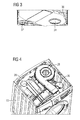
- FIG 4 illustrates a further schematic perspective view of the open laundry washing and drying machine according to an embodiment of the present invention.
- Said open laundry washing and drying machine is the same state as in FIG 2 .
- the tub outlet 26, the fan inlet 28 and the compressor housing 36 are shown.
- FIG 5 illustrates a schematic perspective view of the open laundry washing and drying machine with the module for the heat pump system and two further detailed perspective views according to an embodiment of the present invention.
- the module 30 is inserted into the upper part of the cabinet 10. Further, the compressor 38 is inserted into the compressor housing 36.
- An upper detailed perspective view shows the enhanced representation of the filter arrangement 18.
- the filter arrangement 18 is a part of the module 30 and positioned in the left front corner of said module 30.
- a lower detailed perspective view shows an alternative arrangement of the compressor 38 within the basement of the cabinet 10.
- the alternative position of the compressor 38 is the left front corner in the basement of the cabinet 10.
- FIG 6 illustrates a schematic perspective view of the module 30 for the heat pump system according to an embodiment of the present invention.
- the module 30 comprises the filter arrangement 18, the evaporator 20, the condenser 22 and the compressor 38.
- FIG 7 illustrates a schematic exploded perspective view of the module 30 for the heat pump system according to an embodiment of the present invention.
- FIG 7 is the exploded version of the perspective view in FIG 6 .
- FIG 7 clarifies the positions of the filter arrangement 18, the evaporator 20, the condenser 22 and the compressor 38 within the module 30.
- FIG 8 illustrates a schematic perspective view of the open laundry washing and drying machine according to a further embodiment of the present invention.
- the washing and drying machine comprises the cabinet 10, the drum 14, the tub outlet 26, the fan inlet 28 and the compressor 38.
- the tub outlet 26 is arranged in the front portion of the washing and drying machine whereas the tub inlet is arranged in the rear portion of the washing and drying machine as it can be better seen in figure 8 .
- the fan inlet 28 and the compressor 38 are arranged at the same positions as in the previous described embodiment.
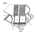
- FIG 9 illustrates a schematic exploded perspective view of the module 30 for the heat pump system according to a further embodiment of the present invention. Unlike the previous described embodiment the tub outlet 26 embodiment is arranged in the front portion of the module 30.
- the laundry washing and drying machine with the integrated heat pump system according to the present invention can be realized as a compact arrangement.
- the heat pump system is fastened at the cabinet 10 and/or tub 12. Since the tub 12 does not oscillate during the rotation of the drum, the heat pump system is not affected by vibration.
- the heat pump system can be arranged easily in the upper part of the laundry washing and drying machine, above the tub, since the stationary tub provides more room in that position and additionally enables the heat pump system to be robustly connected and fixed to the same tub.
- the heat pump system can be integrated in the worktop of the laundry washing and drying machine so that the same worktop defines a module ready to be mounted on the side wall of the cabinet.
- the heat pump system can be fixed to the top wall and/or to the side wall of the cabinet.
- the heat pump system can be fixed to and entirely supported by the tub.
Landscapes
- Engineering & Computer Science (AREA)
- Textile Engineering (AREA)
- Detail Structures Of Washing Machines And Dryers (AREA)
Abstract
Description
- The present invention relates to a laundry machine with an integrated heat pump system.
- It is an efficient way to save energy in a laundry washing and/or drying machine by the heat pump technology. A typical laundry washing and drying machine comprises a closed air stream circuit and a closed refrigerant circuit. The air stream is provided for drying the wet laundry. The air stream circuit and the refrigerant circuit are coupled by at least two heat exchangers.
- However, the components of the heat pump system require space inside the cabinet of the washing and drying machine. At the basement of the cabinet there is usually not enough space for the heat pump system. An appropriate place for the heat pump system is above the tub and the drum. Another problem is the oscillation of the tub and drum during the spinning phase.
-
EP 1 411 163 A2 discloses a washing and drying machine with a heat pump system. The components of the heat pump system are arranged above the tub. Since the tub and the drum are oscillating during the spinning phase, the heat pump system and the tub are connected via flexible hoses. -
EP 1 619 286 B1 discloses a drum type washing machine and a bearing housing structure thereof. The tub is installed in a cabinet. A rotatable drum provided in the tub. The drum is supported by the cabinet via a damping system, so that the tub is stationary. -
WO 2008/103007 A2 discloses a drum type washing machine including a cabinet, the tub provided in the cabinet and a rotatable drum provided in the tub. The rotatable drum is supported by the cabinet via a bearing house and supporting portions, so that the tub is directly connected to the cabinet. - It is an object of the present invention to provide a laundry machine with an integrated heat pump system, which overcomes the above problems and allows a simple installation of the heat pump system within the laundry washing and drying machine.
- The object of the present invention is achieved by the laundry washing and drying machine with an integrated heat pump system according to claim 1.
- The present invention relates to a laundry machine, preferably to a laundry washing and drying machine with an integrated heat pump system, wherein:
- the laundry machine comprises a cabinet,
- a tub is associated to the cabinet,
- an air line is fluidly connected to the tub and to the heat pump system for air recirculation,
- a rotatable drum is arranged within the tub and resiliently supported at the cabinet and/or at the tub,
- so that the tub is stationary with respect of the cabinet during a operation of the machine, in particular during rotation of the drum, and
- at least a part of the components of the heat pump system is supported by the cabinet and/or the tub.
- The main idea of the present invention is the tub arranged stationary with respect of the cabinet during the operation of the laundry washing and drying machine. When the drum rotates, the tub and the cabinet form a stationary unit. The heat pump system and components thereof are supported by the cabinet and/or the tub. The drum may be directly or indirectly connected at the cabinet. Thus, only the drum and adjacent component oscillate during the drum rotation phase, but not the tub and/or the heat pump system.
- According to a preferred embodiment of the present invention the tub comprises or is fluidly connected to an air stream channel, wherein at least one heat exchanger is arranged within said air stream channel. The tub is an integrated part of the air stream channel, so that the air can flow through the tub and the drum. This contributes to a low complexity of the laundry washing and drying machine.
- Further, the air stream channel is supported by the cabinet and/or the tub. This prevents an oscillating of the air stream channel or components thereof.
- Preferably, at least a part of the air stream channel and the tub form a single-piece part. This allows an easy production and contributes to a compact heat pump system. According to a preferred embodiment of the present invention the laundry washing and drying machine comprises at least one module including at least one component of the heat pump system. Thus, the module can be installed at the laundry washing and drying machine in a single step.
- For example, the module includes at least a part of the air stream channel comprising at least one heat exchanger. This contributes to the impermeability of the air stream channel and the heat exchanger.
- According to a preferred embodiment, at least a part of heat pump system (for example at least one heat exchanger) and/or the module is supported, entirely, by the cabinet. In this case the tub needs no special reinforcements.
- For example, the heat pump system is supported by a top wall and/or a side wall of the cabinet.
- In an alternative embodiment, at least a part of heat pump system (for example at least one heat exchanger) and/or the module is supported entirely by the tub.
- In a further embodiment, the heat pump system and/or the module is supported partly by the cabinet and partly by the tub.
- Further, the drum is resiliently supported at the cabinet and/or at the tub by a vibration damping system having one or more dampers and/or spring elements.
- Preferably a bearing housing for supporting a rotation shaft of the drum is provided. The vibration damping system is connected to the bearing housing and to the cabinet so that the vibrating/oscillating elements of the machine, such as the drum, are supported in the cabinet by the bearing housing.
- Preferably the bearing housing is resiliently connected to the rear portion of the tub, for example, by sealing means to prevent vibration from being transmitted from the vibrating/oscillating elements to the tub and to prevent water accommodated in the tub from leaking.
- Preferably the tub comprises a rear portion where the sealing means and the bearing housing are arranged
- Preferably the tub comprises a main body directly fixed to the front side of the cabinet.
- Preferably the vibration damping system comprises one or more damping brackets connected to the bearing housing and one or more dampers or spring elements arranged between the damping bracket and the cabinet.
- Preferably, the drum is driven by a direct drive motor connected to the bearing housing.
- The novel and inventive features believed to be the characteristic of the present invention are set forth in the appending claims.
- The invention will be described in further detail with reference to the drawings, in which
- FIG 1
- illustrates a schematic sectional side view of a laundry washing and drying machine with an integrated heat pump system according to a schematic embodiment of the present invention,
- FIG 2
- illustrates a schematic perspective view of an open laundry washing and drying machine according to an embodiment of the present invention,
- FIG 3
- illustrates a schematic perspective partial view at the bottom side of a module for the heat pump system according to an embodiment of the present invention,
- FIG 4
- illustrates a further schematic perspective view of the open laundry washing and drying machine according to an embodiment of the present invention,
- FIG 5
- illustrates a schematic perspective view of the open laundry washing and drying machine with the module for the heat pump system and two further detailed perspective views according to an embodiment of the present invention,
- FIG 6
- illustrates a schematic perspective view of the module for the heat pump system according to an embodiment of the present invention,
- FIG 7
- illustrates a schematic exploded perspective view of the module for the heat pump system according to an embodiment of the present invention,
- FIG 8
- illustrates a schematic perspective view of the open laundry washing and drying machine according to a further embodiment of the present invention, and
- FIG 9
- illustrates a schematic exploded perspective view of the module for the heat pump system according to the further embodiment of the present invention.
- FIG 10
- illustrates a schematic sectional side view of a laundry washing and drying machine according to preferable embodiment of the present invention.
-
FIG 1 illustrates a schematic sectional side view of a laundry washing and drying machine with an integrated heat pump system according to a schematic embodiment of the present invention. - The laundry washing and drying machine comprises a
cabinet 10 with side walls, a top wall and a bottom frame, atub 12 and arotating drum 14. Thetub 12 is arranged within and directly connected to thecabinet 10, so that thetub 12 is stationary respective to thecabinet 10 also during operation of the machine when the drum rotates. In other words thetub 12 is directly fixed to the cabinet without the need of dampers and/or springs connecting thetub 12 to thecabinet 10. Thedrum 14 is arranged within thetub 12. Thedrum 14 is resiliently supported at thecabinet 10 by avibration damping system 16. In this example thevibration damping system 16 comprises three dampers and/or spring elements. - As schematically show in
figure 10 , the laundry washing and drying machine comprises a bearinghousing 44 having first bearing 46 andsecond bearing 48 for supporting a rotation shaft 50 of thedrum 14. Thevibration damping system 16 connects the bearinghousing 44 to thecabinet 10. -
Tthe drum 14 is driven by adirect drive motor 52 connected to the bearinghousing 44. - The
vibration damping system 16 comprises one or more damping brackets 54 connected to afastening portion 56 of the bearinghousing 44 and one or more dampers and/orspring elements 58 arranged between the damping bracket 54 and thecabinet 10. - When the
drum 14 rotates, thedrum 14, the bearinghousing 44 and themotor 52 transfer vibrations to thecabinet 10 by means of thevibration damping system 16, while thetub 12 is not affected by the vibrations/oscillations. Since thetub 12 is stationary at thecabinet 10, thetub 12 and component fixed at saidtub 12 do not oscillate. - The laundry washing and drying machine comprises further a
filter arrangement 18, anevaporator 20, acondenser 22,fan 24 and adetergent drawer 42. Thefilter arrangement 18, theevaporator 20, thecondenser 22 and thefan 24 are components of the heat pump system. - The heat pump system comprises an open or closed air stream circuit and a closed refrigerant circuit. The air stream circuit is formed by the
drum 14, theevaporator 20, thecondenser 22 and a fan. The refrigerant circuit is formed by acompressor 38, theevaporator 20, thecondenser 22 and optionally an expansion device, for example an expansion valve. -
FIG 2 illustrates a schematic perspective view of an open laundry washing and drying machine according to an embodiment of the present invention. InFIG 2 most of the components for heat pump system are not installed. - The laundry washing and drying machine comprises further a
tub outlet 26 and afan inlet 28. Thetub outlet 26 and thefan inlet 28 are a part of a closed air stream circuit for the heat pump system. Thetub outlet 26 is provided at a rear portion of the washing and drying machine, whereas the tub inlet is provided at a front portion of the washing and drying machine as it can be seen infigure 2 and4 . Additionally, the washing and drying machine comprises acompressor housing 36 provided for inserting acompressor 38. Thecompressor 38 is a part of a refrigerant circuit for the heat pump system. -
FIG 3 illustrates a schematic perspective partial view at the bottom side of amodule 30 for the heat pump system according to an embodiment of the present invention. - The
module 30 includes thefilter arrangement 18, theevaporator 20 and thecondenser 22. Themodule 30 includes further aninlet port 32 for thetub outlet 26 and anoutlet port 34 for thefan inlet 28. Theinlet port 32 and theoutlet port 34 are connectable to thetub outlet 26 and to thefan inlet 28, respectively. - The
module 30 allows a compact form of substantial components of the heat pump system. By inserting themodule 30 into the laundry washing and drying machine the heat pump system or the substantial part thereof may be installed. -
FIG 4 illustrates a further schematic perspective view of the open laundry washing and drying machine according to an embodiment of the present invention. Said open laundry washing and drying machine is the same state as inFIG 2 . In particular, thetub outlet 26, thefan inlet 28 and thecompressor housing 36 are shown. -
FIG 5 illustrates a schematic perspective view of the open laundry washing and drying machine with the module for the heat pump system and two further detailed perspective views according to an embodiment of the present invention. - In
FIG 5 themodule 30 is inserted into the upper part of thecabinet 10. Further, thecompressor 38 is inserted into thecompressor housing 36. - An upper detailed perspective view shows the enhanced representation of the
filter arrangement 18. Thefilter arrangement 18 is a part of themodule 30 and positioned in the left front corner of saidmodule 30. - A lower detailed perspective view shows an alternative arrangement of the
compressor 38 within the basement of thecabinet 10. The alternative position of thecompressor 38 is the left front corner in the basement of thecabinet 10. -
FIG 6 illustrates a schematic perspective view of themodule 30 for the heat pump system according to an embodiment of the present invention. Themodule 30 comprises thefilter arrangement 18, theevaporator 20, thecondenser 22 and thecompressor 38. -
FIG 7 illustrates a schematic exploded perspective view of themodule 30 for the heat pump system according to an embodiment of the present invention.FIG 7 is the exploded version of the perspective view inFIG 6 . -
FIG 7 clarifies the positions of thefilter arrangement 18, theevaporator 20, thecondenser 22 and thecompressor 38 within themodule 30. -
FIG 8 illustrates a schematic perspective view of the open laundry washing and drying machine according to a further embodiment of the present invention. - The washing and drying machine comprises the
cabinet 10, thedrum 14, thetub outlet 26, thefan inlet 28 and thecompressor 38. Unlike the previous described embodiment thetub outlet 26 is arranged in the front portion of the washing and drying machine whereas the tub inlet is arranged in the rear portion of the washing and drying machine as it can be better seen infigure 8 . Thefan inlet 28 and thecompressor 38 are arranged at the same positions as in the previous described embodiment. -
FIG 9 illustrates a schematic exploded perspective view of themodule 30 for the heat pump system according to a further embodiment of the present invention. Unlike the previous described embodiment thetub outlet 26 embodiment is arranged in the front portion of themodule 30. - The laundry washing and drying machine with the integrated heat pump system according to the present invention can be realized as a compact arrangement. The heat pump system is fastened at the
cabinet 10 and/ortub 12. Since thetub 12 does not oscillate during the rotation of the drum, the heat pump system is not affected by vibration. - Further with present invention it is possible to rigidly connect the air line to
tub 12 on one side and to the heat pump system on the other side without the interposition of flexible members. - Further with present invention the heat pump system can be arranged easily in the upper part of the laundry washing and drying machine, above the tub, since the stationary tub provides more room in that position and additionally enables the heat pump system to be robustly connected and fixed to the same tub.
- Although illustrative embodiments of the present invention have been described herein with reference to the accompanying drawings, it is to be understood that the present invention is not limited to those precise embodiments, and that various other changes and modifications may be affected therein by one skilled in the art without departing from the scope or spirit of the invention. All such changes and modifications are intended to be included within the scope of the invention as defined by the appended claims.
- In particular the heat pump system can be integrated in the worktop of the laundry washing and drying machine so that the same worktop defines a module ready to be mounted on the side wall of the cabinet.
- Alternatively the heat pump system can be fixed to the top wall and/or to the side wall of the cabinet. Alternatively the heat pump system can be fixed to and entirely supported by the tub.
-
- 10
- cabinet
- 12
- tub
- 14
- drum
- 16
- vibration damping system
- 18
- filter arrangement
- 20
- evaporator
- 22
- condenser
- 24
- fan
- 26
- tub outlet
- 28
- fan inlet
- 30
- module
- 32
- inlet port for the tub outlet
- 34
- outlet port for the fan inlet
- 36
- compressor housing
- 38
- compressor
- 40
- fan inlet
- 42
- detergent drawer
- 44
- bearing housing
- 46
- first bearing
- 48
- second bearing
- 50
- rotation shaft
- 52
- drive motor
- 54
- damping bracket
- 56
- fastening portion
- 58
- damper and/or spring element
Claims (12)
- A laundry machine with an integrated heat pump system, comprising:- a cabinet,- a tub associated to the cabinet,- an air line fluidly connected to the tub and to the heat pump system for air recirculation,- characterized in, that- a rotatable drum is arranged within the tub and resiliently supported at the cabinet and/or at the tub,- so that the tub is stationary with respect of the cabinet during operation of the machine, in particular during rotation of the drum, and- at least a part of the components of the heat pump system is supported by the cabinet and/or the tub.
- The laundry machine according to claim 1, characterized in, that
the tub (12) comprises or is fluidly connected to an air stream channel, wherein at least one heat exchanger is arranged within said air stream channel. - The laundry machine according to claim 2, characterized in, that
the air stream channel is supported by the cabinet (10) and/or the tub (12). - The laundry machine according to claim 2 or 3, characterized in, that
at least a part of the air stream channel and the tub (12) form a single-piece part. - The laundry machine according to any one of the preceding claims,
characterized in, that
the laundry washing and drying machine comprises at least one module (30) including at least on component (18, 20, 22, 38) of the heat pump system. - The laundry machine according to claim 5, characterized in, that
the module (30) includes at least a part of the air stream channel comprising at least one heat exchanger (20, 22). - The laundry machine according to any one of the preceding claims,
characterized in, that
the heat pump system is supported by the cabinet (10). - The laundry machine according to claim 7, characterized in, that
the heat pump system is supported by a top wall and/or a side wall of the cabinet (10). - The laundry machine according to any one of the preceding claims ,
characterized in, that
the heat pump system is integrated in the worktop of the laundry washing and drying machine so that the same worktop defines a module ready to be mounted on the side wall of the cabinet. - The laundry machine according to any one of the preceding claims,
characterized in, that
the drum (14) is resiliently supported at the cabinet (10) and/or at the tub (12) by a vibration damping system (16). - The laundry machine according to claim 9,
characterized in, that
vibration damping system (16) comprises dampers and/or spring elements (58). - The laundry machine according to any one of the preceding claims,
characterized in, that
the drum (14) is driven by a direct drive motor (52).
Priority Applications (3)
| Application Number | Priority Date | Filing Date | Title |
|---|---|---|---|
| EP10161723.1A EP2385163B1 (en) | 2010-05-03 | 2010-05-03 | A laundry machine with an integrated heat pump system |
| BRPI1102068-7A BRPI1102068B1 (en) | 2010-05-03 | 2011-05-02 | washing machine capable of drying clothes with an integrated heat pump system |
| US13/099,137 US9212441B2 (en) | 2010-05-03 | 2011-05-02 | Laundry machine with an integrated heat pump system |
Applications Claiming Priority (1)
| Application Number | Priority Date | Filing Date | Title |
|---|---|---|---|
| EP10161723.1A EP2385163B1 (en) | 2010-05-03 | 2010-05-03 | A laundry machine with an integrated heat pump system |
Publications (2)
| Publication Number | Publication Date |
|---|---|
| EP2385163A1 true EP2385163A1 (en) | 2011-11-09 |
| EP2385163B1 EP2385163B1 (en) | 2016-10-05 |
Family
ID=42830368
Family Applications (1)
| Application Number | Title | Priority Date | Filing Date |
|---|---|---|---|
| EP10161723.1A Active EP2385163B1 (en) | 2010-05-03 | 2010-05-03 | A laundry machine with an integrated heat pump system |
Country Status (3)
| Country | Link |
|---|---|
| US (1) | US9212441B2 (en) |
| EP (1) | EP2385163B1 (en) |
| BR (1) | BRPI1102068B1 (en) |
Cited By (16)
| Publication number | Priority date | Publication date | Assignee | Title |
|---|---|---|---|---|
| EP2843119A1 (en) * | 2013-08-30 | 2015-03-04 | Electrolux Appliances Aktiebolag | Laundry appliance having overheating preventing system |
| EP2843111A1 (en) * | 2013-08-30 | 2015-03-04 | Electrolux Appliances Aktiebolag | Laundry drying machine |
| WO2015139966A1 (en) * | 2014-03-21 | 2015-09-24 | Electrolux Appliances Aktiebolag | Laundry drying machine |
| EP3176300A1 (en) * | 2015-12-01 | 2017-06-07 | Whirlpool Corporation | Laundry treating appliance |
| EP3252216A1 (en) * | 2016-05-31 | 2017-12-06 | Wuxi Little Swan Co., Ltd. | Clothes dryer or washer-dryer |
| US10036114B2 (en) | 2015-12-01 | 2018-07-31 | Whirlpool Corporation | Laundry treating appliance |
| US10053808B2 (en) | 2015-12-01 | 2018-08-21 | Whirlpool Corporation | Laundry treating appliance |
| US10125446B2 (en) | 2015-12-01 | 2018-11-13 | Whirlpool Corporation | Laundry treating appliance |
| EP2471994B1 (en) * | 2011-01-04 | 2019-06-26 | Electrolux Home Products Corporation N.V. | Appliance for drying laundry |
| US10508384B2 (en) | 2009-06-29 | 2019-12-17 | Electrolux Home Products Corporation N.V. | Top of an appliance for drying laundry providing drying air recirculation and moisture condensation |
| US10519592B2 (en) | 2009-06-29 | 2019-12-31 | Electrolux Home Products Corporation N.V. | Appliance for drying laundry providing drying air recirculation and moisture condensation |
| DE102022131770A1 (en) | 2022-11-30 | 2024-06-06 | Miele & Cie. Kg | Laundry treatment device with heat pump |
| DE102022132520A1 (en) | 2022-12-07 | 2024-06-13 | Miele & Cie. Kg | Laundry treatment device with heat pump |
| DE102022132534A1 (en) | 2022-12-07 | 2024-06-13 | Miele & Cie. Kg | Laundry treatment device with heat pump |
| US20250003138A1 (en) * | 2023-06-29 | 2025-01-02 | Whirlpool Corporation | Laundry Appliance With Heat Pump Having Improved Evaporator Efficiency |
| EP4310242B1 (en) | 2013-01-25 | 2025-07-02 | LG Electronics Inc. | Laundry treatment apparatus |
Families Citing this family (12)
| Publication number | Priority date | Publication date | Assignee | Title |
|---|---|---|---|---|
| KR101224053B1 (en) * | 2010-09-30 | 2013-01-21 | 엘지전자 주식회사 | Clothes treating apparatus with a heat pump system and operating method thereof |
| ITPR20120082A1 (en) * | 2012-11-27 | 2014-05-28 | Meccanica Generale Srl | WASHING MACHINE WITH FRONTAL LOADING WITH INCORPORATED DRYING SYSTEM |
| KR102127383B1 (en) * | 2013-08-01 | 2020-06-26 | 엘지전자 주식회사 | Laundry Machine |
| KR102150442B1 (en) * | 2013-11-11 | 2020-09-01 | 엘지전자 주식회사 | Laundry Machine |
| KR20150081602A (en) | 2014-01-06 | 2015-07-15 | 삼성전자주식회사 | Washing machine with drying apparatus and method to control thereof |
| KR102302326B1 (en) * | 2014-10-28 | 2021-09-15 | 엘지전자 주식회사 | Laundry Machine |
| CN105483970B (en) * | 2016-01-04 | 2018-10-23 | 珠海格力电器股份有限公司 | Washing and drying machine |
| KR102585025B1 (en) | 2016-01-05 | 2023-10-05 | 엘지전자 주식회사 | Clothes treatment apparatus having the heat pump module |
| US20170342646A1 (en) * | 2016-05-31 | 2017-11-30 | Wuxi Little Swan Co., Ltd. | Clothes dryer or washer-dryer |
| CN105951347B (en) * | 2016-05-31 | 2019-05-21 | 无锡小天鹅股份有限公司 | The heat pump mould group and device for clothing processing of device for clothing processing |
| EP3467187B1 (en) | 2017-10-09 | 2021-12-22 | Whirlpool Corporation | Filter configured for being used in a machine for drying laundry and machine for drying laundry equipped with such a filter |
| EP4382656A4 (en) * | 2021-08-04 | 2025-10-01 | Lg Electronics Inc | LAUNDRY TREATMENT DEVICE |
Citations (7)
| Publication number | Priority date | Publication date | Assignee | Title |
|---|---|---|---|---|
| GB2075559A (en) * | 1980-05-03 | 1981-11-18 | Miele & Cie | Washing machine |
| EP1156149A2 (en) * | 2000-05-17 | 2001-11-21 | V-Zug AG | Laundry drier with heat pump |
| EP1411163A2 (en) | 2002-10-16 | 2004-04-21 | Matsushita Electric Industrial Co., Ltd. | Washing and drying machine |
| EP1433891A2 (en) * | 2002-12-27 | 2004-06-30 | Lg Electronics Inc. | Drum type washing machine |
| EP1584734A2 (en) * | 2004-03-13 | 2005-10-12 | Eickel u. Spindeldreher GmbH | Condensing type clothes dryer |
| EP1619286A2 (en) * | 2004-07-20 | 2006-01-25 | Lg Electronics Inc. | Drum type washing machine and bearing housing structure thereof |
| WO2008103007A2 (en) | 2007-02-23 | 2008-08-28 | Lg Electronics Inc. | Drum type washing machine |
Family Cites Families (13)
| Publication number | Priority date | Publication date | Assignee | Title |
|---|---|---|---|---|
| US3089327A (en) * | 1951-09-07 | 1963-05-14 | Murray Corp | Apparatus for the complete laundering of fabrics |
| US2957330A (en) * | 1954-02-26 | 1960-10-25 | Kermit R Cline | Combination washer and drier |
| JP2003181189A (en) * | 2001-12-21 | 2003-07-02 | Toshiba Corp | Washing machine |
| US20050223502A1 (en) * | 2004-04-09 | 2005-10-13 | Kleker Richard G | Apparatus for processing garments including a hanger mechanism |
| US7194823B2 (en) * | 2003-12-08 | 2007-03-27 | Matsushita Electric Industrial Co., Ltd. | Clothes drier |
| JP3739377B2 (en) * | 2003-12-10 | 2006-01-25 | シャープ株式会社 | Washing and drying machine |
| EP1657341A3 (en) * | 2004-11-12 | 2006-08-23 | LG Electronics Inc. | Method and apparatus for control of drying process in a washing and drying machine |
| JP4521297B2 (en) * | 2005-02-22 | 2010-08-11 | 株式会社東芝 | Drum type washer / dryer |
| DE102005013052A1 (en) * | 2005-03-18 | 2006-09-21 | BSH Bosch und Siemens Hausgeräte GmbH | Clothes drying machine |
| JP4889545B2 (en) * | 2007-03-30 | 2012-03-07 | 三洋電機株式会社 | Drying apparatus and washing and drying machine equipped with this apparatus |
| US20090151188A1 (en) * | 2007-08-03 | 2009-06-18 | Lg Electronics | Clothes treating apparatus |
| US8393172B2 (en) * | 2008-09-30 | 2013-03-12 | Sanyo Electric Co., Ltd. | Heat pump drying machine |
| KR101603106B1 (en) * | 2009-03-03 | 2016-03-14 | 엘지전자 주식회사 | Washing machine |
-
2010
- 2010-05-03 EP EP10161723.1A patent/EP2385163B1/en active Active
-
2011
- 2011-05-02 BR BRPI1102068-7A patent/BRPI1102068B1/en active IP Right Grant
- 2011-05-02 US US13/099,137 patent/US9212441B2/en active Active
Patent Citations (8)
| Publication number | Priority date | Publication date | Assignee | Title |
|---|---|---|---|---|
| GB2075559A (en) * | 1980-05-03 | 1981-11-18 | Miele & Cie | Washing machine |
| EP1156149A2 (en) * | 2000-05-17 | 2001-11-21 | V-Zug AG | Laundry drier with heat pump |
| EP1411163A2 (en) | 2002-10-16 | 2004-04-21 | Matsushita Electric Industrial Co., Ltd. | Washing and drying machine |
| EP1433891A2 (en) * | 2002-12-27 | 2004-06-30 | Lg Electronics Inc. | Drum type washing machine |
| EP1584734A2 (en) * | 2004-03-13 | 2005-10-12 | Eickel u. Spindeldreher GmbH | Condensing type clothes dryer |
| EP1619286A2 (en) * | 2004-07-20 | 2006-01-25 | Lg Electronics Inc. | Drum type washing machine and bearing housing structure thereof |
| EP1619286B1 (en) | 2004-07-20 | 2009-08-05 | Lg Electronics Inc. | Drum type washing machine and bearing housing structure thereof |
| WO2008103007A2 (en) | 2007-02-23 | 2008-08-28 | Lg Electronics Inc. | Drum type washing machine |
Cited By (24)
| Publication number | Priority date | Publication date | Assignee | Title |
|---|---|---|---|---|
| US10508384B2 (en) | 2009-06-29 | 2019-12-17 | Electrolux Home Products Corporation N.V. | Top of an appliance for drying laundry providing drying air recirculation and moisture condensation |
| US10519592B2 (en) | 2009-06-29 | 2019-12-31 | Electrolux Home Products Corporation N.V. | Appliance for drying laundry providing drying air recirculation and moisture condensation |
| EP2471994B1 (en) * | 2011-01-04 | 2019-06-26 | Electrolux Home Products Corporation N.V. | Appliance for drying laundry |
| EP4310242B1 (en) | 2013-01-25 | 2025-07-02 | LG Electronics Inc. | Laundry treatment apparatus |
| EP2843119A1 (en) * | 2013-08-30 | 2015-03-04 | Electrolux Appliances Aktiebolag | Laundry appliance having overheating preventing system |
| WO2015028500A1 (en) * | 2013-08-30 | 2015-03-05 | Electrolux Appliances Aktiebolag | Laundry appliance having overheating preventing system |
| EP2843111A1 (en) * | 2013-08-30 | 2015-03-04 | Electrolux Appliances Aktiebolag | Laundry drying machine |
| AU2014314258B2 (en) * | 2013-08-30 | 2019-01-17 | Electrolux Appliances Aktiebolag | Laundry appliance having overheating preventing system |
| CN106029972A (en) * | 2014-03-21 | 2016-10-12 | 伊莱克斯家用电器股份公司 | clothes dryer |
| WO2015139966A1 (en) * | 2014-03-21 | 2015-09-24 | Electrolux Appliances Aktiebolag | Laundry drying machine |
| US9845567B2 (en) | 2014-03-21 | 2017-12-19 | Electrolux Appliances Aktiebolag | Laundry drying machine |
| AU2015233716B2 (en) * | 2014-03-21 | 2019-09-12 | Electrolux Appliances Aktiebolag | Laundry drying machine |
| CN106029972B (en) * | 2014-03-21 | 2019-01-22 | 伊莱克斯家用电器股份公司 | clothes dryer |
| US11236458B2 (en) | 2015-12-01 | 2022-02-01 | Whirlpool Corporation | Laundry treating appliance |
| US10125446B2 (en) | 2015-12-01 | 2018-11-13 | Whirlpool Corporation | Laundry treating appliance |
| US10487432B2 (en) | 2015-12-01 | 2019-11-26 | Whirlpool Corporation | Laundry treating appliance |
| US10053808B2 (en) | 2015-12-01 | 2018-08-21 | Whirlpool Corporation | Laundry treating appliance |
| US10036114B2 (en) | 2015-12-01 | 2018-07-31 | Whirlpool Corporation | Laundry treating appliance |
| EP3176300A1 (en) * | 2015-12-01 | 2017-06-07 | Whirlpool Corporation | Laundry treating appliance |
| EP3252216A1 (en) * | 2016-05-31 | 2017-12-06 | Wuxi Little Swan Co., Ltd. | Clothes dryer or washer-dryer |
| DE102022131770A1 (en) | 2022-11-30 | 2024-06-06 | Miele & Cie. Kg | Laundry treatment device with heat pump |
| DE102022132520A1 (en) | 2022-12-07 | 2024-06-13 | Miele & Cie. Kg | Laundry treatment device with heat pump |
| DE102022132534A1 (en) | 2022-12-07 | 2024-06-13 | Miele & Cie. Kg | Laundry treatment device with heat pump |
| US20250003138A1 (en) * | 2023-06-29 | 2025-01-02 | Whirlpool Corporation | Laundry Appliance With Heat Pump Having Improved Evaporator Efficiency |
Also Published As
| Publication number | Publication date |
|---|---|
| US20110265523A1 (en) | 2011-11-03 |
| BRPI1102068A2 (en) | 2012-10-30 |
| US9212441B2 (en) | 2015-12-15 |
| BRPI1102068B1 (en) | 2020-10-13 |
| EP2385163B1 (en) | 2016-10-05 |
Similar Documents
| Publication | Publication Date | Title |
|---|---|---|
| EP2385163B1 (en) | A laundry machine with an integrated heat pump system | |
| AU2016385261B2 (en) | Clothing treatment apparatus comprising heat pump module | |
| KR101663610B1 (en) | Laundry Machine | |
| CN114908508B (en) | laundry treatment device | |
| CN112095280B (en) | Drum washing machine and its pipe fixing parts | |
| JP2019502086A (en) | Gas-liquid separator and clothing processing apparatus including the same | |
| EP4538447A2 (en) | Clothing processing apparatus | |
| KR20230124653A (en) | clothes handling device | |
| JP4557747B2 (en) | Washing machine | |
| JP4676407B2 (en) | Drum type washer / dryer | |
| JP2020018915A (en) | Clothes dryer | |
| JP5921249B2 (en) | Vibration isolator for compressor | |
| EP4043636A1 (en) | Laundry treating apparatus | |
| KR20230111012A (en) | Laundry Treatment Apparatus | |
| JP2012024137A (en) | Clothing drier | |
| JP2024535611A (en) | Clothes Processing Equipment | |
| KR20220114266A (en) | Laundry Treatment Apparatus | |
| EP3124683A1 (en) | Laundry dryer | |
| KR20220114283A (en) | Landaury treating apparatus | |
| KR20220045540A (en) | Landaury treating apparatus | |
| EP4039877A1 (en) | Laundry treating apparatus | |
| KR101414644B1 (en) | Laundry machine | |
| KR101752414B1 (en) | Laundry machine having a drying function | |
| US20260117451A1 (en) | Heat pump dryer including a horizontally mounted blower assembly | |
| KR101848660B1 (en) | Laundry Treating Device |
Legal Events
| Date | Code | Title | Description |
|---|---|---|---|
| AK | Designated contracting states |
Kind code of ref document: A1 Designated state(s): AL AT BE BG CH CY CZ DE DK EE ES FI FR GB GR HR HU IE IS IT LI LT LU LV MC MK MT NL NO PL PT RO SE SI SK SM TR |
|
| AX | Request for extension of the european patent |
Extension state: BA ME RS |
|
| PUAI | Public reference made under article 153(3) epc to a published international application that has entered the european phase |
Free format text: ORIGINAL CODE: 0009012 |
|
| 17P | Request for examination filed |
Effective date: 20120509 |
|
| GRAP | Despatch of communication of intention to grant a patent |
Free format text: ORIGINAL CODE: EPIDOSNIGR1 |
|
| INTG | Intention to grant announced |
Effective date: 20160615 |
|
| GRAS | Grant fee paid |
Free format text: ORIGINAL CODE: EPIDOSNIGR3 |
|
| GRAA | (expected) grant |
Free format text: ORIGINAL CODE: 0009210 |
|
| AK | Designated contracting states |
Kind code of ref document: B1 Designated state(s): AL AT BE BG CH CY CZ DE DK EE ES FI FR GB GR HR HU IE IS IT LI LT LU LV MC MK MT NL NO PL PT RO SE SI SK SM TR |
|
| REG | Reference to a national code |
Ref country code: GB Ref legal event code: FG4D |
|
| REG | Reference to a national code |
Ref country code: CH Ref legal event code: EP |
|
| REG | Reference to a national code |
Ref country code: AT Ref legal event code: REF Ref document number: 834784 Country of ref document: AT Kind code of ref document: T Effective date: 20161015 |
|
| REG | Reference to a national code |
Ref country code: IE Ref legal event code: FG4D |
|
| REG | Reference to a national code |
Ref country code: DE Ref legal event code: R096 Ref document number: 602010036888 Country of ref document: DE |
|
| REG | Reference to a national code |
Ref country code: NL Ref legal event code: MP Effective date: 20161005 |
|
| REG | Reference to a national code |
Ref country code: LT Ref legal event code: MG4D |
|
| PG25 | Lapsed in a contracting state [announced via postgrant information from national office to epo] |
Ref country code: LV Free format text: LAPSE BECAUSE OF FAILURE TO SUBMIT A TRANSLATION OF THE DESCRIPTION OR TO PAY THE FEE WITHIN THE PRESCRIBED TIME-LIMIT Effective date: 20161005 |
|
| REG | Reference to a national code |
Ref country code: AT Ref legal event code: MK05 Ref document number: 834784 Country of ref document: AT Kind code of ref document: T Effective date: 20161005 |
|
| PG25 | Lapsed in a contracting state [announced via postgrant information from national office to epo] |
Ref country code: GR Free format text: LAPSE BECAUSE OF FAILURE TO SUBMIT A TRANSLATION OF THE DESCRIPTION OR TO PAY THE FEE WITHIN THE PRESCRIBED TIME-LIMIT Effective date: 20170106 Ref country code: NO Free format text: LAPSE BECAUSE OF FAILURE TO SUBMIT A TRANSLATION OF THE DESCRIPTION OR TO PAY THE FEE WITHIN THE PRESCRIBED TIME-LIMIT Effective date: 20170105 Ref country code: LT Free format text: LAPSE BECAUSE OF FAILURE TO SUBMIT A TRANSLATION OF THE DESCRIPTION OR TO PAY THE FEE WITHIN THE PRESCRIBED TIME-LIMIT Effective date: 20161005 Ref country code: SE Free format text: LAPSE BECAUSE OF FAILURE TO SUBMIT A TRANSLATION OF THE DESCRIPTION OR TO PAY THE FEE WITHIN THE PRESCRIBED TIME-LIMIT Effective date: 20161005 |
|
| REG | Reference to a national code |
Ref country code: FR Ref legal event code: PLFP Year of fee payment: 8 |
|
| PG25 | Lapsed in a contracting state [announced via postgrant information from national office to epo] |
Ref country code: AT Free format text: LAPSE BECAUSE OF FAILURE TO SUBMIT A TRANSLATION OF THE DESCRIPTION OR TO PAY THE FEE WITHIN THE PRESCRIBED TIME-LIMIT Effective date: 20161005 Ref country code: HR Free format text: LAPSE BECAUSE OF FAILURE TO SUBMIT A TRANSLATION OF THE DESCRIPTION OR TO PAY THE FEE WITHIN THE PRESCRIBED TIME-LIMIT Effective date: 20161005 Ref country code: FI Free format text: LAPSE BECAUSE OF FAILURE TO SUBMIT A TRANSLATION OF THE DESCRIPTION OR TO PAY THE FEE WITHIN THE PRESCRIBED TIME-LIMIT Effective date: 20161005 Ref country code: PT Free format text: LAPSE BECAUSE OF FAILURE TO SUBMIT A TRANSLATION OF THE DESCRIPTION OR TO PAY THE FEE WITHIN THE PRESCRIBED TIME-LIMIT Effective date: 20170206 Ref country code: ES Free format text: LAPSE BECAUSE OF FAILURE TO SUBMIT A TRANSLATION OF THE DESCRIPTION OR TO PAY THE FEE WITHIN THE PRESCRIBED TIME-LIMIT Effective date: 20161005 Ref country code: IS Free format text: LAPSE BECAUSE OF FAILURE TO SUBMIT A TRANSLATION OF THE DESCRIPTION OR TO PAY THE FEE WITHIN THE PRESCRIBED TIME-LIMIT Effective date: 20170205 Ref country code: NL Free format text: LAPSE BECAUSE OF FAILURE TO SUBMIT A TRANSLATION OF THE DESCRIPTION OR TO PAY THE FEE WITHIN THE PRESCRIBED TIME-LIMIT Effective date: 20161005 Ref country code: PL Free format text: LAPSE BECAUSE OF FAILURE TO SUBMIT A TRANSLATION OF THE DESCRIPTION OR TO PAY THE FEE WITHIN THE PRESCRIBED TIME-LIMIT Effective date: 20161005 Ref country code: BE Free format text: LAPSE BECAUSE OF FAILURE TO SUBMIT A TRANSLATION OF THE DESCRIPTION OR TO PAY THE FEE WITHIN THE PRESCRIBED TIME-LIMIT Effective date: 20161005 |
|
| REG | Reference to a national code |
Ref country code: DE Ref legal event code: R097 Ref document number: 602010036888 Country of ref document: DE |
|
| PG25 | Lapsed in a contracting state [announced via postgrant information from national office to epo] |
Ref country code: CZ Free format text: LAPSE BECAUSE OF FAILURE TO SUBMIT A TRANSLATION OF THE DESCRIPTION OR TO PAY THE FEE WITHIN THE PRESCRIBED TIME-LIMIT Effective date: 20161005 Ref country code: SK Free format text: LAPSE BECAUSE OF FAILURE TO SUBMIT A TRANSLATION OF THE DESCRIPTION OR TO PAY THE FEE WITHIN THE PRESCRIBED TIME-LIMIT Effective date: 20161005 Ref country code: DK Free format text: LAPSE BECAUSE OF FAILURE TO SUBMIT A TRANSLATION OF THE DESCRIPTION OR TO PAY THE FEE WITHIN THE PRESCRIBED TIME-LIMIT Effective date: 20161005 Ref country code: EE Free format text: LAPSE BECAUSE OF FAILURE TO SUBMIT A TRANSLATION OF THE DESCRIPTION OR TO PAY THE FEE WITHIN THE PRESCRIBED TIME-LIMIT Effective date: 20161005 Ref country code: RO Free format text: LAPSE BECAUSE OF FAILURE TO SUBMIT A TRANSLATION OF THE DESCRIPTION OR TO PAY THE FEE WITHIN THE PRESCRIBED TIME-LIMIT Effective date: 20161005 |
|
| PLBE | No opposition filed within time limit |
Free format text: ORIGINAL CODE: 0009261 |
|
| STAA | Information on the status of an ep patent application or granted ep patent |
Free format text: STATUS: NO OPPOSITION FILED WITHIN TIME LIMIT |
|
| PG25 | Lapsed in a contracting state [announced via postgrant information from national office to epo] |
Ref country code: BG Free format text: LAPSE BECAUSE OF FAILURE TO SUBMIT A TRANSLATION OF THE DESCRIPTION OR TO PAY THE FEE WITHIN THE PRESCRIBED TIME-LIMIT Effective date: 20170105 Ref country code: SM Free format text: LAPSE BECAUSE OF FAILURE TO SUBMIT A TRANSLATION OF THE DESCRIPTION OR TO PAY THE FEE WITHIN THE PRESCRIBED TIME-LIMIT Effective date: 20161005 Ref country code: LU Free format text: LAPSE BECAUSE OF NON-PAYMENT OF DUE FEES Effective date: 20170531 |
|
| 26N | No opposition filed |
Effective date: 20170706 |
|
| PG25 | Lapsed in a contracting state [announced via postgrant information from national office to epo] |
Ref country code: SI Free format text: LAPSE BECAUSE OF FAILURE TO SUBMIT A TRANSLATION OF THE DESCRIPTION OR TO PAY THE FEE WITHIN THE PRESCRIBED TIME-LIMIT Effective date: 20161005 |
|
| REG | Reference to a national code |
Ref country code: CH Ref legal event code: PL |
|
| PG25 | Lapsed in a contracting state [announced via postgrant information from national office to epo] |
Ref country code: MC Free format text: LAPSE BECAUSE OF FAILURE TO SUBMIT A TRANSLATION OF THE DESCRIPTION OR TO PAY THE FEE WITHIN THE PRESCRIBED TIME-LIMIT Effective date: 20161005 |
|
| REG | Reference to a national code |
Ref country code: IE Ref legal event code: MM4A |
|
| PG25 | Lapsed in a contracting state [announced via postgrant information from national office to epo] |
Ref country code: CH Free format text: LAPSE BECAUSE OF NON-PAYMENT OF DUE FEES Effective date: 20170531 Ref country code: LI Free format text: LAPSE BECAUSE OF NON-PAYMENT OF DUE FEES Effective date: 20170531 |
|
| PG25 | Lapsed in a contracting state [announced via postgrant information from national office to epo] |
Ref country code: LU Free format text: LAPSE BECAUSE OF NON-PAYMENT OF DUE FEES Effective date: 20170503 |
|
| PG25 | Lapsed in a contracting state [announced via postgrant information from national office to epo] |
Ref country code: IE Free format text: LAPSE BECAUSE OF NON-PAYMENT OF DUE FEES Effective date: 20170503 |
|
| REG | Reference to a national code |
Ref country code: FR Ref legal event code: PLFP Year of fee payment: 9 |
|
| PG25 | Lapsed in a contracting state [announced via postgrant information from national office to epo] |
Ref country code: MT Free format text: LAPSE BECAUSE OF NON-PAYMENT OF DUE FEES Effective date: 20170503 |
|
| PG25 | Lapsed in a contracting state [announced via postgrant information from national office to epo] |
Ref country code: HU Free format text: LAPSE BECAUSE OF FAILURE TO SUBMIT A TRANSLATION OF THE DESCRIPTION OR TO PAY THE FEE WITHIN THE PRESCRIBED TIME-LIMIT; INVALID AB INITIO Effective date: 20100503 |
|
| PG25 | Lapsed in a contracting state [announced via postgrant information from national office to epo] |
Ref country code: CY Free format text: LAPSE BECAUSE OF NON-PAYMENT OF DUE FEES Effective date: 20161005 |
|
| PG25 | Lapsed in a contracting state [announced via postgrant information from national office to epo] |
Ref country code: MK Free format text: LAPSE BECAUSE OF FAILURE TO SUBMIT A TRANSLATION OF THE DESCRIPTION OR TO PAY THE FEE WITHIN THE PRESCRIBED TIME-LIMIT Effective date: 20161005 |
|
| PG25 | Lapsed in a contracting state [announced via postgrant information from national office to epo] |
Ref country code: TR Free format text: LAPSE BECAUSE OF FAILURE TO SUBMIT A TRANSLATION OF THE DESCRIPTION OR TO PAY THE FEE WITHIN THE PRESCRIBED TIME-LIMIT Effective date: 20161005 |
|
| PG25 | Lapsed in a contracting state [announced via postgrant information from national office to epo] |
Ref country code: AL Free format text: LAPSE BECAUSE OF FAILURE TO SUBMIT A TRANSLATION OF THE DESCRIPTION OR TO PAY THE FEE WITHIN THE PRESCRIBED TIME-LIMIT Effective date: 20161005 |
|
| P01 | Opt-out of the competence of the unified patent court (upc) registered |
Effective date: 20230625 |
|
| PGFP | Annual fee paid to national office [announced via postgrant information from national office to epo] |
Ref country code: DE Payment date: 20250528 Year of fee payment: 16 |
|
| PGFP | Annual fee paid to national office [announced via postgrant information from national office to epo] |
Ref country code: GB Payment date: 20250520 Year of fee payment: 16 |
|
| PGFP | Annual fee paid to national office [announced via postgrant information from national office to epo] |
Ref country code: IT Payment date: 20250522 Year of fee payment: 16 |
|
| PGFP | Annual fee paid to national office [announced via postgrant information from national office to epo] |
Ref country code: FR Payment date: 20250526 Year of fee payment: 16 |