EP2384779B1 - Anesthetic compound needle - Google Patents
Anesthetic compound needle Download PDFInfo
- Publication number
- EP2384779B1 EP2384779B1 EP09841855.1A EP09841855A EP2384779B1 EP 2384779 B1 EP2384779 B1 EP 2384779B1 EP 09841855 A EP09841855 A EP 09841855A EP 2384779 B1 EP2384779 B1 EP 2384779B1
- Authority
- EP
- European Patent Office
- Prior art keywords
- needle
- proximal end
- outer needle
- inner needle
- end portion
- Prior art date
- Legal status (The legal status is an assumption and is not a legal conclusion. Google has not performed a legal analysis and makes no representation as to the accuracy of the status listed.)
- Active
Links
Images




Classifications
-
- A—HUMAN NECESSITIES
- A61—MEDICAL OR VETERINARY SCIENCE; HYGIENE
- A61B—DIAGNOSIS; SURGERY; IDENTIFICATION
- A61B17/00—Surgical instruments, devices or methods
- A61B17/34—Trocars; Puncturing needles
- A61B17/3401—Puncturing needles for the peridural or subarachnoid space or the plexus, e.g. for anaesthesia
-
- A—HUMAN NECESSITIES
- A61—MEDICAL OR VETERINARY SCIENCE; HYGIENE
- A61B—DIAGNOSIS; SURGERY; IDENTIFICATION
- A61B17/00—Surgical instruments, devices or methods
- A61B17/34—Trocars; Puncturing needles
- A61B2017/347—Locking means, e.g. for locking instrument in cannula
-
- A—HUMAN NECESSITIES
- A61—MEDICAL OR VETERINARY SCIENCE; HYGIENE
- A61M—DEVICES FOR INTRODUCING MEDIA INTO, OR ONTO, THE BODY; DEVICES FOR TRANSDUCING BODY MEDIA OR FOR TAKING MEDIA FROM THE BODY; DEVICES FOR PRODUCING OR ENDING SLEEP OR STUPOR
- A61M5/00—Devices for bringing media into the body in a subcutaneous, intra-vascular or intramuscular way; Accessories therefor, e.g. filling or cleaning devices, arm rests
- A61M5/14—Infusion devices, e.g. infusing by gravity; Blood infusion; Accessories therefor
- A61M5/158—Needles for infusions; Accessories therefor, e.g. for inserting infusion needles, or for holding them on the body
Definitions
- the present invention relates to an anesthetic compound needle for administering epidural anesthesia or spinal anesthesia.
- a compound needle including outer and inner needles as disclosed in Patent Document 1 below Japanese Unexamined Utility Model Registration Application Publication No. 6-44549
- the outer needle is inserted in order to cause a distal end thereof to reach the epidural space.
- the inner needle is inserted into the outer needle so as to cause a distal end thereof to protrude from the distal end of the outer needle, to penetrate through the dura mater, and to reach the subarachnoidal space.
- spinal anesthesia is administered by injecting an anesthetic solution through the inner needle into the subarachnoidal space.
- Patent Document 2 Japanese Unexamined Patent Application Publication No. 10-305101 discloses a compound needle, an inner needle of which can be fixed as described above.
- a base portion of a proximal end of an outer needle and a proximal end portion of a proximal end of an inner needle are threadably engaged with each other.
- the inner needle when rotated, can be advanced or retracted relative to the outer needle, and when not rotated, fixed relative to the outer needle.
- Patent Document 3 Japanese Unexamined Patent Application Publication No. 2002-306596 discloses a technology that overcomes the above-described problems.
- an unlocked state in which the inner needle can be advanced or retracted relative to the outer needle
- a locked state in which the inner needle cannot be advanced or retracted relative to the outer needle
- the unlocked state the inner needle can be straightly advanced relative to the outer needle without resistance.
- the amount of rotation of the inner needle can be markedly reduced compared to that in the technology disclosed in Patent Document 2 above, and accordingly, can cause the moment when the distal end of the inner needle is inserted into the dura mater to be clearly sensed due to insertion resistance.
- the locked and unlocked states are switched by rotating the inner needle.
- US 5 480 389 A describes a regulating device for extending and/or retracting a spinal needle relative to an epidural needle.
- the device includes a pair of sliding members to which any combination of epidural and spinal needles can be separately fixed.
- An actuating tab may be biasingly fixed to an outer sliding tube, and include a mating portion for engaging with a complimentary structured surface formed on or in an innermost tube, for regulating operation of the device between a free position and a locking position.
- An object of the present invention is to develop an anesthetic compound needle that allows an unlocked state, in which the inner needle can be advanced or retracted relative to the outer needle, and a locked state, in which the inner needle cannot be advanced or retracted relative to the outer needle, to be switched by a simple operation without rotating the inner needle; and that allows the moment when the distal end of the inner needle is inserted into the dura mater to be clearly sensed.
- an anesthetic compound needle which includes an outer needle, an inner needle, and a tubular adaptor, in which a front portion of a tubular inner needle proximal end portion disposed at a proximal end of the inner needle is attached to a rear end portion of the adaptor, a tubular outer needle proximal end portion disposed at a proximal end of the outer needle is inserted from a distal end of the adaptor, and a distal end of the inner needle is caused to protrude from a distal end of the outer needle, in which a plurality of grooves are formed in parallel in a peripheral direction along an axial direction of the outer needle proximal end portion at least in a lower surface of the outer needle proximal end portion, in which a restricting plate having an insertion hole through which the outer needle proximal end portion is inserted is inserted into the adaptor from an opening formed in an upper surface of the adaptor, and the adaptor is provided with urging means that urges the
- the present invention has the above-described structure, with a simple operation of pushing down the restricting plate, the groove of an insertion portion and the protrusion of the restricting plate are disengaged from each other and the inner needle is set to the unlocked state in which the inner needle is able to be advanced or retracted relative to the outer needle.
- the inner needle can be advanced and the moment when the distal end of the inner needle is inserted into the dura mater can be clearly sensed.
- the restricting plate When the pushing down of the restricting plate is released (finger is removed from the restricting plate), the restricting plate automatically moves up due to the operation of the urging means, one of the grooves of the insertion portion and the protrusion of the restricting plate are engaged with each other, and the inner needle is set to the locked state in which the inner needle is unable to be advanced or retracted relative to the outer needle.
- the inner needle there is no possibility of the inner needle moving relative to the outer needle when an anesthetic solution is injected through the inner needle into the subarachnoidal space, and spinal anesthesia can be safely administered.
- the urging means is a plate spring portion defined by forming a cutout portion in a lower surface of the adaptor.
- the urging means according to the present invention is not particularly limited to a specific component.
- the urging means may include a highly elastic material such as a plate spring formed as a separate member, a coil spring, or rubber attached to a lower portion of the adaptor.
- the plate spring portion by defining the plate spring portion by forming the cutout in the lower surface of the adaptor, that is, by forming the cutout portion around the plate spring portion except part of it, the plate spring portion can be used as the urging means due to elasticity of a material (plastic, metal, or the like) of the adaptor without providing the urging means of the separate member.
- a material plastic, metal, or the like
- a finger contact portion bent in a horizontal direction may be formed in an upper portion of the restricting plate.
- a finger By forming the finger contact portion, a finger can be placed on the finger contact portion when restricting plate is pushed down. Thus, an area with which the finger is in contact is increased, and accordingly, the operation can be easily and reliably performed.
- the locked and unlocked states of the inner needle can be switched by a simple operation of pushing down of the restricting plate or by releasing the pushing down of the restricting plate without rotating the inner needle.
- the inner needle being casually advanced or retracted when the state of the inner needle is switched, and accordingly, an anesthesia procedure can be safely performed.
- a compound needle according to the present invention includes an inner needle and an outer needle.
- a tubular outer needle proximal end portion 2 (formed of plastic) is disposed at a proximal end of an outer needle 1.
- a number of grooves 2a are formed in parallel in an upper surface in a peripheral direction and a lower surface of the outer needle proximal end portion 2 along the axial direction of the outer needle proximal end portion 2. It is sufficient that the grooves in the peripheral direction are formed at least in the lower surface of the outer needle proximal end portion. However, if the grooves are also formed in the upper surface as in the present embodiment, the outer needle or the inner needle can be used even when the needle is vertically inverted.
- the grooves in the peripheral direction may also be formed around the whole periphery of the outer needle proximal end portion.
- the outer needle proximal end portion 2 also includes a blade 2b mounted therein, which assists in inserting the outer needle and in switching between unlocked and locked states of the inner needle.
- a distal end of the outer needle 1 includes a distal end bent portion 1b, which is bent upward in an elbow-like shape.
- the distal end bent portion 1b has a through hole 1c, from which a distal end of an inner needle 3 protrudes.
- the distal end bent portion 1b also has a blade edge hole 1d from which a distal end of a catheter protrudes.
- the outer needle 1 is inserted into a body with an outer needle stylet (not shown) inserted thereinto from the rear of the outer needle proximal end portion 2 while the through hole 1c and the blade edge hole 1d are substantially blocked.
- This is the same as with a related art compound needle.
- the purpose of this is the prevention of damage to skin tissue or the like of a patient by the outer through hole 1c and the blade edge hole 1d.
- a plastic proximal end portion is provided at a proximal end of the outer needle stylet so as to cause the proximal end portion of the outer needle stylet to be engaged with a rear end portion of the outer needle proximal end portion 2 when the outer needle stylet has been inserted through the outer needle 1.
- the inner needle 3 is inserted into the outer needle 1, the distal end of which protrudes from the through hole 1c at the distal end of the outer needle 1 ( Fig. 11 ).
- a tubular inner needle proximal end portion 4 (formed of plastic) is disposed at a proximal end of the inner needle 3.
- the inner needle proximal end portion 4 includes a tubular insert portion 4a at a front portion thereof.
- a peripheral groove 4b which is engaged with an adaptor, is formed around the insert portion.
- a medicine receiving portion 4c used to receive a medicine is formed at a rear end of the inner needle proximal end portion 4.
- an inner needle stylet (not shown) is inserted into the inner needle when the inner needle 3 is inserted into the outer needle 1.
- the position of a distal end of the stylet substantially matches the position of the distal end of the inner needle.
- a blade edge hole of the inner needle is substantially blocked. The purpose of this is the prevention of damage to tissues such as dura mater when the inner needle 3 is caused to protrude from the through hole at the distal end of the outer needle 1.
- a plastic proximal end portion is provided at a proximal end of the inner needle stylet so as to cause the proximal end portion of the stylet to be engaged with the rear end portion of the inner needle proximal end portion 4 when the inner needle stylet has been inserted through the inner needle 3.
- an adaptor 5 is formed of plastic and has a tubular shape.
- the outer needle proximal end portion 2 is inserted into the adaptor 5 from a front end side, and the insert portion 4a of the inner needle proximal end portion 4 is inserted into the adaptor 5 from a rear end side.
- An annular rib 5d is formed around an inner peripheral surface at the rear end side of the adaptor 5 so as to be engaged with the inner needle proximal end portion.
- An opening 5a is formed in an upper surface of the adaptor 5, through which a restricting plate 6 is inserted.
- a plate spring portion 5c is formed, which is defined by a cutout portion 5b.
- the plate spring portion 5c has a rectangular shape and functions as a plate spring because of the formation of the cutout portion 5b around the plate spring portion 5c except part of it (a side on the right in Fig. 6 ).
- part of the cutout portion 5b is larger than the remaining part thereof in order to prevent the cutout portion 5b from interfering with the restricting plate 6 when the plate is pushed down.
- a large cutout portion such as this may not be required. For example, such a large cutout portion is unnecessary if the bottom of the adaptor is deeper in that portion.
- Fig. 7 relates to the restricting plate 6, illustrating a front view on the upper left, a side view on the upper right, and a sectional view taken along line B-B on the lover left.
- the restricting plate is formed to have a plate-like shape, an upper portion of which is bent at substantially right angle into a horizontal direction so as to define a finger contact portion 6c, and of which a lower portion has a circular arc shape that matches the inner peripheral shape of the adaptor 5.
- An insertion hole 6a is formed through the restricting plate in the axial direction in order for the outer needle proximal end portion 2 to be inserted therethrough.
- the horizontal width of the insertion hole 6a is equal to or a little larger than the horizontal width of the outer needle proximal end portion 2.
- the vertical width of the insertion hole 6a is larger than the vertical width of the outer needle proximal end portion 2 so as not to obstruct pushing down of the restricting plate.
- a protrusion 6b is formed on a lower surface of the insertion hole 6a and protrudes upward.
- the section of the protrusion 6b has a U-shape similar to that of each groove 2a of the outer needle proximal end portion 2.
- the inner needle proximal end portion 4 is attached to the adaptor 5 by inserting the insert portion 4a from the rear end side of the adaptor 5 such that the peripheral groove 4b is engaged with the annular rib 5d.
- the adaptor and the inner needle proximal end portion are integrated into a unit. In this state, the restricting plate 6 does not fall off the adaptor 5 because of the inner needle 3 being inserted through the insertion hole 6a.
- the method of attaching the front portion of the inner needle proximal end portion to the rear end portion of the adaptor is not limited to the engagement as illustrated in the present embodiment. Any method including adhesion with adhesive or welding of a plastic material may be used.
- the inner needle 3 In order to insert the inner needle 3 into the outer needle 1, as illustrated in Fig. 9 , a finger is placed on the finger contact portion 6c so as to push down the restricting plate 6. In this state, the outer needle proximal end portion 2 is inserted into the adaptor 5. At this time, the plate spring portion 5c is pushed down by the restricting plate 6 and deformed, and the protrusion 6b is not engaged with any of the grooves 2a. Thus, the inner needle can be freely advanced or retracted (unlocked state).
- the finger is removed from the finger contact portion 6c when the inner needle comes to an appropriate position (releasing of pushing down).
- This causes the plate spring portion 5c to restore the original position owing to the elasticity thereof, thereby pushing up the restricting plate 6 and causing the protrusion 6b to be engaged with one of the grooves 2a.
- the inner needle cannot be advanced or retracted relative to the outer needle (locked state).
- An anesthetic compound needle according to the present embodiment is used as follows. That is, the outer needle 1 is inserted into a patient with the outer needle stylet (not shown) is inserted therethrough, and the distal end thereof is caused to reach an epidural space 12. The outer needle stylet is removed while keeping the outer needle 1 at the position it has reached. Next, the inner needle 3 (engaged with the adaptor) is inserted into the outer needle with the inner needle stylet inserted therethrough. When the outer needle proximal end portion 2 is inserted into the adaptor, the restricting plate 6 is pushed down by a finger placed on the finger contact portion 6c. In this state, the inner needle 3 is advanced.
- the distal end of the inner needle 3 is caused to protrude from the through hole at the distal end of the outer needle 1, to penetrate through the dura mater 11, and to reach a subarachnoidal space 10 as illustrated in Fig. 11 . Since the state at this time is, as illustrated in Fig. 9 , the unlocked state in which the protrusion 6b is not engaged with any of the grooves 2a, the adaptor 5 can be straightly advanced or retracted without resistance relative to the outer needle proximal end portion 2 (that is, the inner needle 3 relative to the outer needle 1). Thus, a moment when the distal end of the inner needle is inserted into the dura mater can be clearly sensed, and accordingly, the percentage of success in spinal anesthesia is increased.
- the finger is removed from the finger contact portion 6c (releasing of pushing down) so as to set the inner needle to the locked state in which the inner needle cannot be advanced or retracted relative to the outer needle
- the inner needle stylet is removed while keeping the outer needle 1 and the inner needle 3 at the positions they have reached
- a medicine injecting device such as an injector is connected to the medicine receiving portion 4c of the inner needle proximal end portion 4, and spinal anesthesia is administered by injecting an anesthetic solution from the distal end of the inner needle 3 into the subarachnoidal space 10 ( Fig. 11 ). Since the inner needle 3 is set to the locked state, the series of above operations can be safely performed.
- epidural anesthesia can also be administered after that by performing the following operation. That is, the inner needle 3 is set to the unlocked state by pushing down the finger contact portion 6c (restricting plate 6), the inner needle 3 is removed from the outer needle 1, and a catheter 9 instead of the inner needle 3 is inserted through the outer needle 1. The distal end of the catheter 9 is caused to protrude from the blade edge hole 1d of the outer needle 1, only the outer needle 1 is removed, and the anesthetic solution is injected from the catheter 9 kept in the position it has reached into the epidural space 12 ( Fig. 12 ).
Landscapes
- Health & Medical Sciences (AREA)
- Surgery (AREA)
- Life Sciences & Earth Sciences (AREA)
- Heart & Thoracic Surgery (AREA)
- Nuclear Medicine, Radiotherapy & Molecular Imaging (AREA)
- Pathology (AREA)
- Engineering & Computer Science (AREA)
- Biomedical Technology (AREA)
- Anesthesiology (AREA)
- Medical Informatics (AREA)
- Molecular Biology (AREA)
- Animal Behavior & Ethology (AREA)
- General Health & Medical Sciences (AREA)
- Public Health (AREA)
- Veterinary Medicine (AREA)
- Infusion, Injection, And Reservoir Apparatuses (AREA)
Description
- The present invention relates to an anesthetic compound needle for administering epidural anesthesia or spinal anesthesia.
- As an anesthetic needle used to administer spinal anesthesia, a compound needle including outer and inner needles as disclosed in Patent Document 1 below (Japanese Unexamined Utility Model Registration Application Publication No.
6-44549 Patent Document 2 below (Japanese Unexamined Patent Application Publication No.10-305101 - Although a mechanism disclosed in
Patent Document 2 above in which the proximal end portions of the inner and outer needles are threadably engaged with each other can fix the inner needle relative to the outer needle, the inner needle needs to be rotated in order to be advanced or retracted. Thus, operation is very complex. In addition, there is a significant disadvantage that insertion of the inner needle into the dura mater cannot be sensed. -
Patent Document 3 below (Japanese Unexamined Patent Application Publication No.2002-306596 - Patent Document 1: Japanese Unexamined Utility Model Registration Application Publication No.
6-44549 - Patent Document 2: Japanese Unexamined Patent Application Publication No.
10-305101 - Patent Document 3: Japanese Unexamined Patent Application Publication No.
2002-306596 - With the technology disclosed in
Patent Document 3 above, the amount of rotation of the inner needle can be markedly reduced compared to that in the technology disclosed inPatent Document 2 above, and accordingly, can cause the moment when the distal end of the inner needle is inserted into the dura mater to be clearly sensed due to insertion resistance. However, the locked and unlocked states are switched by rotating the inner needle. Some anesthesiologists suggest that it is unavoidable that the internal needle, when it is rotated, is slightly advanced or retracted. Thus, the anesthesiologists need to pay close attention while administering anesthesia. Still, in many cases, there is a possibility of damaging nerve tissue due to advancement of the inner needle and a possibility of failure of spinal anesthesia caused by removal of the distal end of the inner needle from the dura mater due to retraction of the inner needle. -
US 5 480 389 A describes a regulating device for extending and/or retracting a spinal needle relative to an epidural needle. The device includes a pair of sliding members to which any combination of epidural and spinal needles can be separately fixed. An actuating tab may be biasingly fixed to an outer sliding tube, and include a mating portion for engaging with a complimentary structured surface formed on or in an innermost tube, for regulating operation of the device between a free position and a locking position. - An object of the present invention is to develop an anesthetic compound needle that allows an unlocked state, in which the inner needle can be advanced or retracted relative to the outer needle, and a locked state, in which the inner needle cannot be advanced or retracted relative to the outer needle, to be switched by a simple operation without rotating the inner needle; and that allows the moment when the distal end of the inner needle is inserted into the dura mater to be clearly sensed.
- The present invention is defined in and by the appended claims.
- Described herein is an anesthetic compound needle which includes an outer needle, an inner needle, and a tubular adaptor, in which a front portion of a tubular inner needle proximal end portion disposed at a proximal end of the inner needle is attached to a rear end portion of the adaptor, a tubular outer needle proximal end portion disposed at a proximal end of the outer needle is inserted from a distal end of the adaptor, and a distal end of the inner needle is caused to protrude from a distal end of the outer needle,
in which a plurality of grooves are formed in parallel in a peripheral direction along an axial direction of the outer needle proximal end portion at least in a lower surface of the outer needle proximal end portion,
in which a restricting plate having an insertion hole through which the outer needle proximal end portion is inserted is inserted into the adaptor from an opening formed in an upper surface of the adaptor, and the adaptor is provided with urging means that urges the restricting plate upward when the restricting plate is pushed downward and that pushes the restricting plate upward when the pushing-down force is released,
in which a protrusion that protrudes upward and engages with one of the grooves of the outer needle proximal end portion is formed on a lower surface of the insertion hole of the restricting plate,
in which, when the restricting plate is pushed down, the groove of the outer needle proximal end portion and the protrusion of the restricting plate are disengaged from each other and the inner needle is set to an unlocked state in which the inner needle is able to be advanced or retracted relative to the outer needle, and in which, when the pushing down is released, the restricting plate moves up and one of the grooves of the outer needle proximal end portion and the protrusion of the restricting plate are engaged with each other and the inner needle is set to a locked state in which the inner needle is unable to be advanced or retracted relative to the outer needle. - Since the present invention has the above-described structure, with a simple operation of pushing down the restricting plate, the groove of an insertion portion and the protrusion of the restricting plate are disengaged from each other and the inner needle is set to the unlocked state in which the inner needle is able to be advanced or retracted relative to the outer needle. Thus, the inner needle can be advanced and the moment when the distal end of the inner needle is inserted into the dura mater can be clearly sensed. When the pushing down of the restricting plate is released (finger is removed from the restricting plate), the restricting plate automatically moves up due to the operation of the urging means, one of the grooves of the insertion portion and the protrusion of the restricting plate are engaged with each other, and the inner needle is set to the locked state in which the inner needle is unable to be advanced or retracted relative to the outer needle. Thus, there is no possibility of the inner needle moving relative to the outer needle when an anesthetic solution is injected through the inner needle into the subarachnoidal space, and spinal anesthesia can be safely administered.
- According to the present invention, the urging means is a plate spring portion defined by forming a cutout portion in a lower surface of the adaptor.
- The urging means according to the present invention is not particularly limited to a specific component. The urging means may include a highly elastic material such as a plate spring formed as a separate member, a coil spring, or rubber attached to a lower portion of the adaptor. However, by defining the plate spring portion by forming the cutout in the lower surface of the adaptor, that is, by forming the cutout portion around the plate spring portion except part of it, the plate spring portion can be used as the urging means due to elasticity of a material (plastic, metal, or the like) of the adaptor without providing the urging means of the separate member. Thus, due to the reduced number of assembly members, assembly work and cost can be reduced, and the size of the adaptor can also be made as small as possible.
- According to the present invention, a finger contact portion bent in a horizontal direction may be formed in an upper portion of the restricting plate.
- By forming the finger contact portion, a finger can be placed on the finger contact portion when restricting plate is pushed down. Thus, an area with which the finger is in contact is increased, and accordingly, the operation can be easily and reliably performed.
- In the anesthetic compound needle according to the present invention, the locked and unlocked states of the inner needle can be switched by a simple operation of pushing down of the restricting plate or by releasing the pushing down of the restricting plate without rotating the inner needle. Thus, there is no possibility of the inner needle being casually advanced or retracted when the state of the inner needle is switched, and accordingly, an anesthesia procedure can be safely performed. Brief Description of Drawings
- [
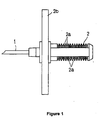
Fig. 1] Fig. 1 is a side view of an outer needle proximal end portion. - [
Fig. 2] Fig. 2 is a rear view of the outer needle proximal end portion. - [
Fig. 3] Fig. 3 is a plan view of an inner needle proximal end portion. - [
Fig. 4] Fig. 4 is a plan view of an adaptor. - [
Fig. 5] Fig. 5 is a sectional view of the adaptor illustrated inFig. 4 taken along line A-A. - [
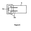
Fig. 6] Fig. 6 is a bottom view of the adaptor. - [
Fig. 7] Fig. 7 includes front and side views of a restricting plate, and a sectional view of the restricting plate taken along line B-B. - [
Fig. 8] Fig. 8 is a longitudinal sectional view of a state in which the inner needle proximal end portion is engaged with the adaptor. - [
Fig. 9] Fig. 9 is a sectional explanatory view of a compound needle of which the inner needle is set to an unlocked state relative to the outer needle. - [
Fig. 10] Fig. 10 is a sectional explanatory view of the compound needle of which the inner needle is set to a locked state relative to the outer needle. - [
Fig. 11] Fig. 11 is an explanatory view illustrating how an anesthetic compound needle according to an embodiment is used. - [
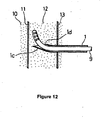
Fig. 12] Fig. 12 is an explanatory view illustrating how the anesthetic compound needle according to the embodiment is used. -
- 1
- outer needle
- 1b
- distal end bent portion
- 1c
- through hole
- 1d
- blade edge hole
- 2
- outer needle proximal end portion
- 2a
- groove
- 2b
- blade
- 3
- inner needle
- 4
- inner needle proximal end portion
- 4a
- insert portion
- 4b
- peripheral groove
- 4c
- medicine receiving portion
- 5
- adaptor
- 5a
- opening
- 5b
- cutout portion
- 5c
- plate spring portion
- 5d
- annular rib
- 6
- restricting plate
- 6a
- insertion hole
- 6b
- protrusion
- 6c
- finger contact portion
- 9
- catheter
- 10
- subarachnoidal space
- 11
- dura mater
- 12
- epidural space
- 13
- yellow ligament
- The present invention will be described in detail below with reference to the drawings relating to an embodiment.
- A compound needle according to the present invention includes an inner needle and an outer needle.
- As illustrated in
Figs. 1 and2 , a tubular outer needle proximal end portion 2 (formed of plastic) is disposed at a proximal end of an outer needle 1. A number ofgrooves 2a are formed in parallel in an upper surface in a peripheral direction and a lower surface of the outer needleproximal end portion 2 along the axial direction of the outer needleproximal end portion 2. It is sufficient that the grooves in the peripheral direction are formed at least in the lower surface of the outer needle proximal end portion. However, if the grooves are also formed in the upper surface as in the present embodiment, the outer needle or the inner needle can be used even when the needle is vertically inverted. The grooves in the peripheral direction may also be formed around the whole periphery of the outer needle proximal end portion. - The outer needle
proximal end portion 2 also includes ablade 2b mounted therein, which assists in inserting the outer needle and in switching between unlocked and locked states of the inner needle. - As illustrated in
Figs. 11 and12 , a distal end of the outer needle 1 includes a distal end bent portion 1b, which is bent upward in an elbow-like shape. The distal end bent portion 1b has a throughhole 1c, from which a distal end of aninner needle 3 protrudes. The distal end bent portion 1b also has ablade edge hole 1d from which a distal end of a catheter protrudes. - The outer needle 1 is inserted into a body with an outer needle stylet (not shown) inserted thereinto from the rear of the outer needle
proximal end portion 2 while the throughhole 1c and theblade edge hole 1d are substantially blocked. This is the same as with a related art compound needle. The purpose of this is the prevention of damage to skin tissue or the like of a patient by the outer throughhole 1c and theblade edge hole 1d. After the outer needle has been inserted, the outer needle stylet is removed from the outer needle. A plastic proximal end portion is provided at a proximal end of the outer needle stylet so as to cause the proximal end portion of the outer needle stylet to be engaged with a rear end portion of the outer needleproximal end portion 2 when the outer needle stylet has been inserted through the outer needle 1. - As illustrated in
Figs. 9 and10 , theinner needle 3 is inserted into the outer needle 1, the distal end of which protrudes from the throughhole 1c at the distal end of the outer needle 1 (Fig. 11 ). A tubular inner needle proximal end portion 4 (formed of plastic) is disposed at a proximal end of theinner needle 3. The inner needleproximal end portion 4 includes atubular insert portion 4a at a front portion thereof. Aperipheral groove 4b, which is engaged with an adaptor, is formed around the insert portion. A medicine receiving portion 4c used to receive a medicine is formed at a rear end of the inner needleproximal end portion 4. - As is the case with a related art compound needle, an inner needle stylet (not shown) is inserted into the inner needle when the
inner needle 3 is inserted into the outer needle 1. When the inner needle stylet has been inserted, the position of a distal end of the stylet substantially matches the position of the distal end of the inner needle. Thus, a blade edge hole of the inner needle is substantially blocked. The purpose of this is the prevention of damage to tissues such as dura mater when theinner needle 3 is caused to protrude from the through hole at the distal end of the outer needle 1. A plastic proximal end portion is provided at a proximal end of the inner needle stylet so as to cause the proximal end portion of the stylet to be engaged with the rear end portion of the inner needleproximal end portion 4 when the inner needle stylet has been inserted through theinner needle 3. - As illustrated in
Figs. 4 to 6 , anadaptor 5 is formed of plastic and has a tubular shape. The outer needleproximal end portion 2 is inserted into theadaptor 5 from a front end side, and theinsert portion 4a of the inner needleproximal end portion 4 is inserted into theadaptor 5 from a rear end side. Anannular rib 5d is formed around an inner peripheral surface at the rear end side of theadaptor 5 so as to be engaged with the inner needle proximal end portion. - An
opening 5a is formed in an upper surface of theadaptor 5, through which a restrictingplate 6 is inserted. In a lower surface of theadaptor 5, aplate spring portion 5c is formed, which is defined by acutout portion 5b. Theplate spring portion 5c has a rectangular shape and functions as a plate spring because of the formation of thecutout portion 5b around theplate spring portion 5c except part of it (a side on the right inFig. 6 ). As illustrated inFig. 6 , part of thecutout portion 5b is larger than the remaining part thereof in order to prevent thecutout portion 5b from interfering with the restrictingplate 6 when the plate is pushed down. A large cutout portion such as this may not be required. For example, such a large cutout portion is unnecessary if the bottom of the adaptor is deeper in that portion. -
Fig. 7 relates to the restrictingplate 6, illustrating a front view on the upper left, a side view on the upper right, and a sectional view taken along line B-B on the lover left. The restricting plate is formed to have a plate-like shape, an upper portion of which is bent at substantially right angle into a horizontal direction so as to define afinger contact portion 6c, and of which a lower portion has a circular arc shape that matches the inner peripheral shape of theadaptor 5. Aninsertion hole 6a is formed through the restricting plate in the axial direction in order for the outer needleproximal end portion 2 to be inserted therethrough. The horizontal width of theinsertion hole 6a is equal to or a little larger than the horizontal width of the outer needleproximal end portion 2. The vertical width of theinsertion hole 6a is larger than the vertical width of the outer needleproximal end portion 2 so as not to obstruct pushing down of the restricting plate. Aprotrusion 6b is formed on a lower surface of theinsertion hole 6a and protrudes upward. The section of theprotrusion 6b has a U-shape similar to that of eachgroove 2a of the outer needleproximal end portion 2. - After the restricting
plate 6 is inserted into theadaptor 5 through theopening 5a, as illustrated inFig. 8 , the inner needleproximal end portion 4 is attached to theadaptor 5 by inserting theinsert portion 4a from the rear end side of theadaptor 5 such that theperipheral groove 4b is engaged with theannular rib 5d. Thus, the adaptor and the inner needle proximal end portion are integrated into a unit. In this state, the restrictingplate 6 does not fall off theadaptor 5 because of theinner needle 3 being inserted through theinsertion hole 6a. - The method of attaching the front portion of the inner needle proximal end portion to the rear end portion of the adaptor is not limited to the engagement as illustrated in the present embodiment. Any method including adhesion with adhesive or welding of a plastic material may be used.
- In order to insert the
inner needle 3 into the outer needle 1, as illustrated inFig. 9 , a finger is placed on thefinger contact portion 6c so as to push down the restrictingplate 6. In this state, the outer needleproximal end portion 2 is inserted into theadaptor 5. At this time, theplate spring portion 5c is pushed down by the restrictingplate 6 and deformed, and theprotrusion 6b is not engaged with any of thegrooves 2a. Thus, the inner needle can be freely advanced or retracted (unlocked state). - As illustrated in
Fig. 10 , the finger is removed from thefinger contact portion 6c when the inner needle comes to an appropriate position (releasing of pushing down). This causes theplate spring portion 5c to restore the original position owing to the elasticity thereof, thereby pushing up the restrictingplate 6 and causing theprotrusion 6b to be engaged with one of thegrooves 2a. Thus, the inner needle cannot be advanced or retracted relative to the outer needle (locked state). - An anesthetic compound needle according to the present embodiment is used as follows. That is, the outer needle 1 is inserted into a patient with the outer needle stylet (not shown) is inserted therethrough, and the distal end thereof is caused to reach an
epidural space 12. The outer needle stylet is removed while keeping the outer needle 1 at the position it has reached. Next, the inner needle 3 (engaged with the adaptor) is inserted into the outer needle with the inner needle stylet inserted therethrough. When the outer needleproximal end portion 2 is inserted into the adaptor, the restrictingplate 6 is pushed down by a finger placed on thefinger contact portion 6c. In this state, theinner needle 3 is advanced. - The distal end of the
inner needle 3 is caused to protrude from the through hole at the distal end of the outer needle 1, to penetrate through thedura mater 11, and to reach asubarachnoidal space 10 as illustrated inFig. 11 . Since the state at this time is, as illustrated inFig. 9 , the unlocked state in which theprotrusion 6b is not engaged with any of thegrooves 2a, theadaptor 5 can be straightly advanced or retracted without resistance relative to the outer needle proximal end portion 2 (that is, theinner needle 3 relative to the outer needle 1). Thus, a moment when the distal end of the inner needle is inserted into the dura mater can be clearly sensed, and accordingly, the percentage of success in spinal anesthesia is increased. - Then, the finger is removed from the
finger contact portion 6c (releasing of pushing down) so as to set the inner needle to the locked state in which the inner needle cannot be advanced or retracted relative to the outer needle, the inner needle stylet is removed while keeping the outer needle 1 and theinner needle 3 at the positions they have reached, a medicine injecting device such as an injector is connected to the medicine receiving portion 4c of the inner needleproximal end portion 4, and spinal anesthesia is administered by injecting an anesthetic solution from the distal end of theinner needle 3 into the subarachnoidal space 10 (Fig. 11 ). Since theinner needle 3 is set to the locked state, the series of above operations can be safely performed. In addition, depending on the case, epidural anesthesia can also be administered after that by performing the following operation. That is, theinner needle 3 is set to the unlocked state by pushing down thefinger contact portion 6c (restricting plate 6), theinner needle 3 is removed from the outer needle 1, and a catheter 9 instead of theinner needle 3 is inserted through the outer needle 1. The distal end of the catheter 9 is caused to protrude from theblade edge hole 1d of the outer needle 1, only the outer needle 1 is removed, and the anesthetic solution is injected from the catheter 9 kept in the position it has reached into the epidural space 12 (Fig. 12 ). - Spinal anesthesia has a strong and immediate effect but does not last long. Epidural anesthesia has a weaker effect but lasts longer compared to spinal anesthesia. With a combined use of spinal anesthesia and epidural anesthesia, anesthesia can be administered in a more ideal manner.
Claims (2)
- An anesthetic compound needle, comprising an outer needle (1), an inner needle (3), and a tubular adaptor (5), wherein a front portion of a tubular inner needle proximal end portion (4) disposed at a proximal end of the inner needle is attached to a rear end portion of the adaptor (5), a tubular outer needle proximal end portion (2) disposed at a proximal end of the outer needle is inserted from a distal end of the adaptor (5), and a distal end of the inner needle (3) is caused to protrude from a distal end of the outer needle (1),
wherein a plurality of grooves (2a) are formed in parallel in a peripheral direction along an axial direction of the outer needle proximal end portion (2) at least in a lower surface of the outer needle proximal end portion (2),
wherein a restricting plate (6) having an insertion hole (6a) through which the outer needle proximal end portion (2) is inserted is inserted into the adaptor (5) from an opening (5a) formed in an upper surface of the adaptor (5), the adaptor (5) being provided with urging means that urges the restricting plate (6) upward when the restricting plate (6) is pushed downward and that pushes the restricting plate (6) upward when the pushing-down force is released,
wherein the urging means is a plate spring portion (5c) defined by forming a cutout portion (5b) in a lower surface of the adaptor (5),
wherein a protrusion (6b) is formed on a lower surface of the insertion hole (6a) of the restricting plate (6), the protrusion (6b) protruding upward and engaging with one of the grooves (2a) of the outer needle proximal end portion (2),
wherein, when the restricting plate (6) is pushed down, the groove (2a) of the outer needle proximal end portion (2) and the protrusion (6b) of the restricting plate (6) are disengaged from each other and the inner needle (3) is set to an unlocked state in which the inner needle (3) is able to be advanced or retracted relative to the outer needle (1), and wherein, when the pushing down is released, the restricting plate (6) moves up and one of the grooves (2a) of the outer needle proximal end portion (2) and the protrusion (6b) of the restricting plate (6) are engaged with each other and the inner needle (3) is set to a locked state in which the inner needle (3) is unable to be advanced or retracted relative to the outer needle (1). - The anesthetic compound needle according to Claim 1, wherein a finger contact portion (6c) bent in a horizontal direction is formed in an upper portion of the restricting plate (6).
Applications Claiming Priority (1)
| Application Number | Priority Date | Filing Date | Title |
|---|---|---|---|
| PCT/JP2009/055295 WO2010106650A1 (en) | 2009-03-18 | 2009-03-18 | Anesthetic compound needle |
Publications (3)
| Publication Number | Publication Date |
|---|---|
| EP2384779A1 EP2384779A1 (en) | 2011-11-09 |
| EP2384779A4 EP2384779A4 (en) | 2012-05-23 |
| EP2384779B1 true EP2384779B1 (en) | 2014-05-07 |
Family
ID=42016889
Family Applications (1)
| Application Number | Title | Priority Date | Filing Date |
|---|---|---|---|
| EP09841855.1A Active EP2384779B1 (en) | 2009-03-18 | 2009-03-18 | Anesthetic compound needle |
Country Status (4)
| Country | Link |
|---|---|
| US (1) | US8728036B2 (en) |
| EP (1) | EP2384779B1 (en) |
| JP (1) | JP4418031B1 (en) |
| WO (1) | WO2010106650A1 (en) |
Families Citing this family (6)
| Publication number | Priority date | Publication date | Assignee | Title |
|---|---|---|---|---|
| US7811261B2 (en) | 2008-06-02 | 2010-10-12 | Sta-Med, Llc | Needle cover assembly for a syringe |
| US8162882B2 (en) | 2010-06-23 | 2012-04-24 | Sta-Med, Llc | Automatic-locking safety needle covers and methods of use and manufacture |
| WO2012166746A1 (en) | 2011-05-31 | 2012-12-06 | Sta-Med, Llc | Blood collection safety devices and methods of use and manufacture |
| CN106037895A (en) * | 2016-07-05 | 2016-10-26 | 王刚 | Dual-channel acoustic-guided epidural puncture needle |
| CN111420175B (en) * | 2020-05-15 | 2021-11-02 | 咸宁市中心医院 | Medical infusion bottle plug |
| EP4167877B1 (en) * | 2020-09-02 | 2024-04-24 | Angiomed GmbH & Co. Medizintechnik KG | Puncture device for creating a tips shunt |
Family Cites Families (14)
| Publication number | Priority date | Publication date | Assignee | Title |
|---|---|---|---|---|
| US5135505A (en) * | 1991-04-15 | 1992-08-04 | Hemedix International, Inc. | Protective catheter device |
| JPH0644549A (en) | 1992-07-24 | 1994-02-18 | Toshiba Corp | Magnetic recording medium and manufacturing method thereof |
| JPH085714Y2 (en) | 1992-11-24 | 1996-02-21 | 株式会社ユニシス | Compound needle for anesthesia |
| US5320608A (en) * | 1993-01-29 | 1994-06-14 | Gerrone Carmen J | Combined pneumo-needle and trocar apparatus |
| US5456673A (en) * | 1994-03-23 | 1995-10-10 | Stryker Corporation | Locking cannula for endoscopic surgery |
| US5480389A (en) * | 1994-08-09 | 1996-01-02 | Becton, Dickinson And Company | Method and apparatus for adjusting the length of a combined spinal-epidural needle |
| US5836914A (en) | 1995-09-15 | 1998-11-17 | Becton Dickinson And Company | Method and apparatus for variably regulating the length of a combined spinal-epidural needle |
| US5871470A (en) | 1997-04-18 | 1999-02-16 | Becton Dickinson And Company | Combined spinal epidural needle set |
| US7682370B2 (en) * | 1998-08-20 | 2010-03-23 | Zimmer Spine, Inc. | Surgical tool for use in expanding a cannula |
| JP2001353219A (en) | 2000-06-15 | 2001-12-25 | Asahi Optical Co Ltd | Endoscope puncture device |
| JP2002306596A (en) | 2001-04-18 | 2002-10-22 | Unisis:Kk | Composite needle for anesthesia |
| JP4191409B2 (en) | 2001-12-28 | 2008-12-03 | テルモ株式会社 | Syringe |
| AU2003235155A1 (en) * | 2003-04-15 | 2004-11-04 | Doctor Japan Co., Ltd. | Medical anesthetic needle |
| US7927271B2 (en) * | 2006-05-17 | 2011-04-19 | C.R. Bard, Inc. | Endoscope tool coupling |
-
2009
- 2009-03-18 WO PCT/JP2009/055295 patent/WO2010106650A1/en not_active Ceased
- 2009-03-18 JP JP2009531649A patent/JP4418031B1/en active Active
- 2009-03-18 EP EP09841855.1A patent/EP2384779B1/en active Active
- 2009-03-18 US US13/144,012 patent/US8728036B2/en active Active
Also Published As
| Publication number | Publication date |
|---|---|
| US20110276014A1 (en) | 2011-11-10 |
| EP2384779A1 (en) | 2011-11-09 |
| JPWO2010106650A1 (en) | 2012-09-20 |
| US8728036B2 (en) | 2014-05-20 |
| WO2010106650A1 (en) | 2010-09-23 |
| EP2384779A4 (en) | 2012-05-23 |
| JP4418031B1 (en) | 2010-02-17 |
Similar Documents
| Publication | Publication Date | Title |
|---|---|---|
| EP2628451B1 (en) | Suture retention device | |
| EP3210637B1 (en) | Infusion set | |
| US8728036B2 (en) | Anesthetic compound needle | |
| ES2941650T3 (en) | Midline and long-term catheters and related assembly methods | |
| EP2231235B1 (en) | Pen needle assembly with needle insertion mechanism | |
| EP1110571B1 (en) | Needle safety device | |
| US8591467B2 (en) | Vascular access assembly and safety device | |
| US8029477B2 (en) | Applier with safety for implantable medical device | |
| CN204219535U (en) | Pen needle assemblies | |
| US20100130941A1 (en) | Audible And Tactile Feedback | |
| US20070149947A1 (en) | Audible and tactile feedback | |
| US8702742B2 (en) | Trocar system having a drive | |
| US8858509B2 (en) | Needle based helical coil safety device | |
| EP2063938A1 (en) | Needle protection device comprising a distal protection element and a proximal protection element | |
| WO2014145263A1 (en) | Single-use needle assembly and method | |
| JP2014528304A (en) | Needle safety device | |
| DE602004013125T2 (en) | SAFETY NEEDLE PROTECTION FOR SPRAYING | |
| US20080171983A1 (en) | Needle hub assembly | |
| JP2010051702A (en) | Subcutaneous infusion device | |
| US20080167623A1 (en) | Indwelling needle | |
| US20050015054A1 (en) | Syringe needle protecting cover | |
| US12246147B2 (en) | Indwelling needle assembly | |
| CN115835898B (en) | The catheter device includes a catheter assembly with a catheter hub, a high-pressure clamp, and a needle shield, and a method for assembling the catheter device. | |
| JP2002306596A (en) | Composite needle for anesthesia | |
| US7914501B2 (en) | Indwelling needle |
Legal Events
| Date | Code | Title | Description |
|---|---|---|---|
| PUAI | Public reference made under article 153(3) epc to a published international application that has entered the european phase |
Free format text: ORIGINAL CODE: 0009012 |
|
| 17P | Request for examination filed |
Effective date: 20110801 |
|
| AK | Designated contracting states |
Kind code of ref document: A1 Designated state(s): AT BE BG CH CY CZ DE DK EE ES FI FR GB GR HR HU IE IS IT LI LT LU LV MC MK MT NL NO PL PT RO SE SI SK TR |
|
| A4 | Supplementary search report drawn up and despatched |
Effective date: 20120419 |
|
| RIC1 | Information provided on ipc code assigned before grant |
Ipc: A61B 17/34 20060101ALI20120413BHEP Ipc: A61M 5/158 20060101AFI20120413BHEP Ipc: A61M 5/32 20060101ALI20120413BHEP |
|
| DAX | Request for extension of the european patent (deleted) | ||
| 17Q | First examination report despatched |
Effective date: 20121220 |
|
| GRAP | Despatch of communication of intention to grant a patent |
Free format text: ORIGINAL CODE: EPIDOSNIGR1 |
|
| INTG | Intention to grant announced |
Effective date: 20130530 |
|
| GRAP | Despatch of communication of intention to grant a patent |
Free format text: ORIGINAL CODE: EPIDOSNIGR1 |
|
| RAP1 | Party data changed (applicant data changed or rights of an application transferred) |
Owner name: UNISIS CORP. |
|
| RIN1 | Information on inventor provided before grant (corrected) |
Inventor name: SAITOH, HIDEYA Inventor name: SARUYA, AKIHIRO |
|
| INTG | Intention to grant announced |
Effective date: 20131014 |
|
| GRAS | Grant fee paid |
Free format text: ORIGINAL CODE: EPIDOSNIGR3 |
|
| GRAA | (expected) grant |
Free format text: ORIGINAL CODE: 0009210 |
|
| AK | Designated contracting states |
Kind code of ref document: B1 Designated state(s): AT BE BG CH CY CZ DE DK EE ES FI FR GB GR HR HU IE IS IT LI LT LU LV MC MK MT NL NO PL PT RO SE SI SK TR |
|
| REG | Reference to a national code |
Ref country code: GB Ref legal event code: FG4D |
|
| REG | Reference to a national code |
Ref country code: AT Ref legal event code: REF Ref document number: 666112 Country of ref document: AT Kind code of ref document: T Effective date: 20140515 |
|
| REG | Reference to a national code |
Ref country code: IE Ref legal event code: FG4D |
|
| REG | Reference to a national code |
Ref country code: DE Ref legal event code: R096 Ref document number: 602009024027 Country of ref document: DE Effective date: 20140618 |
|
| REG | Reference to a national code |
Ref country code: AT Ref legal event code: MK05 Ref document number: 666112 Country of ref document: AT Kind code of ref document: T Effective date: 20140507 |
|
| REG | Reference to a national code |
Ref country code: NL Ref legal event code: VDEP Effective date: 20140507 |
|
| REG | Reference to a national code |
Ref country code: LT Ref legal event code: MG4D |
|
| PG25 | Lapsed in a contracting state [announced via postgrant information from national office to epo] |
Ref country code: NO Free format text: LAPSE BECAUSE OF FAILURE TO SUBMIT A TRANSLATION OF THE DESCRIPTION OR TO PAY THE FEE WITHIN THE PRESCRIBED TIME-LIMIT Effective date: 20140807 Ref country code: CY Free format text: LAPSE BECAUSE OF FAILURE TO SUBMIT A TRANSLATION OF THE DESCRIPTION OR TO PAY THE FEE WITHIN THE PRESCRIBED TIME-LIMIT Effective date: 20140507 Ref country code: GR Free format text: LAPSE BECAUSE OF FAILURE TO SUBMIT A TRANSLATION OF THE DESCRIPTION OR TO PAY THE FEE WITHIN THE PRESCRIBED TIME-LIMIT Effective date: 20140808 Ref country code: IS Free format text: LAPSE BECAUSE OF FAILURE TO SUBMIT A TRANSLATION OF THE DESCRIPTION OR TO PAY THE FEE WITHIN THE PRESCRIBED TIME-LIMIT Effective date: 20140907 Ref country code: FI Free format text: LAPSE BECAUSE OF FAILURE TO SUBMIT A TRANSLATION OF THE DESCRIPTION OR TO PAY THE FEE WITHIN THE PRESCRIBED TIME-LIMIT Effective date: 20140507 Ref country code: LT Free format text: LAPSE BECAUSE OF FAILURE TO SUBMIT A TRANSLATION OF THE DESCRIPTION OR TO PAY THE FEE WITHIN THE PRESCRIBED TIME-LIMIT Effective date: 20140507 |
|
| PG25 | Lapsed in a contracting state [announced via postgrant information from national office to epo] |
Ref country code: AT Free format text: LAPSE BECAUSE OF FAILURE TO SUBMIT A TRANSLATION OF THE DESCRIPTION OR TO PAY THE FEE WITHIN THE PRESCRIBED TIME-LIMIT Effective date: 20140507 Ref country code: ES Free format text: LAPSE BECAUSE OF FAILURE TO SUBMIT A TRANSLATION OF THE DESCRIPTION OR TO PAY THE FEE WITHIN THE PRESCRIBED TIME-LIMIT Effective date: 20140507 Ref country code: HR Free format text: LAPSE BECAUSE OF FAILURE TO SUBMIT A TRANSLATION OF THE DESCRIPTION OR TO PAY THE FEE WITHIN THE PRESCRIBED TIME-LIMIT Effective date: 20140507 Ref country code: PL Free format text: LAPSE BECAUSE OF FAILURE TO SUBMIT A TRANSLATION OF THE DESCRIPTION OR TO PAY THE FEE WITHIN THE PRESCRIBED TIME-LIMIT Effective date: 20140507 Ref country code: LV Free format text: LAPSE BECAUSE OF FAILURE TO SUBMIT A TRANSLATION OF THE DESCRIPTION OR TO PAY THE FEE WITHIN THE PRESCRIBED TIME-LIMIT Effective date: 20140507 Ref country code: SE Free format text: LAPSE BECAUSE OF FAILURE TO SUBMIT A TRANSLATION OF THE DESCRIPTION OR TO PAY THE FEE WITHIN THE PRESCRIBED TIME-LIMIT Effective date: 20140507 |
|
| PG25 | Lapsed in a contracting state [announced via postgrant information from national office to epo] |
Ref country code: SK Free format text: LAPSE BECAUSE OF FAILURE TO SUBMIT A TRANSLATION OF THE DESCRIPTION OR TO PAY THE FEE WITHIN THE PRESCRIBED TIME-LIMIT Effective date: 20140507 Ref country code: EE Free format text: LAPSE BECAUSE OF FAILURE TO SUBMIT A TRANSLATION OF THE DESCRIPTION OR TO PAY THE FEE WITHIN THE PRESCRIBED TIME-LIMIT Effective date: 20140507 Ref country code: CZ Free format text: LAPSE BECAUSE OF FAILURE TO SUBMIT A TRANSLATION OF THE DESCRIPTION OR TO PAY THE FEE WITHIN THE PRESCRIBED TIME-LIMIT Effective date: 20140507 Ref country code: RO Free format text: LAPSE BECAUSE OF FAILURE TO SUBMIT A TRANSLATION OF THE DESCRIPTION OR TO PAY THE FEE WITHIN THE PRESCRIBED TIME-LIMIT Effective date: 20140507 Ref country code: BE Free format text: LAPSE BECAUSE OF FAILURE TO SUBMIT A TRANSLATION OF THE DESCRIPTION OR TO PAY THE FEE WITHIN THE PRESCRIBED TIME-LIMIT Effective date: 20140507 Ref country code: DK Free format text: LAPSE BECAUSE OF FAILURE TO SUBMIT A TRANSLATION OF THE DESCRIPTION OR TO PAY THE FEE WITHIN THE PRESCRIBED TIME-LIMIT Effective date: 20140507 |
|
| REG | Reference to a national code |
Ref country code: DE Ref legal event code: R097 Ref document number: 602009024027 Country of ref document: DE |
|
| PG25 | Lapsed in a contracting state [announced via postgrant information from national office to epo] |
Ref country code: NL Free format text: LAPSE BECAUSE OF FAILURE TO SUBMIT A TRANSLATION OF THE DESCRIPTION OR TO PAY THE FEE WITHIN THE PRESCRIBED TIME-LIMIT Effective date: 20140507 |
|
| PLBE | No opposition filed within time limit |
Free format text: ORIGINAL CODE: 0009261 |
|
| STAA | Information on the status of an ep patent application or granted ep patent |
Free format text: STATUS: NO OPPOSITION FILED WITHIN TIME LIMIT |
|
| 26N | No opposition filed |
Effective date: 20150210 |
|
| PG25 | Lapsed in a contracting state [announced via postgrant information from national office to epo] |
Ref country code: IT Free format text: LAPSE BECAUSE OF FAILURE TO SUBMIT A TRANSLATION OF THE DESCRIPTION OR TO PAY THE FEE WITHIN THE PRESCRIBED TIME-LIMIT Effective date: 20140507 |
|
| REG | Reference to a national code |
Ref country code: DE Ref legal event code: R097 Ref document number: 602009024027 Country of ref document: DE Effective date: 20150210 |
|
| PG25 | Lapsed in a contracting state [announced via postgrant information from national office to epo] |
Ref country code: SI Free format text: LAPSE BECAUSE OF FAILURE TO SUBMIT A TRANSLATION OF THE DESCRIPTION OR TO PAY THE FEE WITHIN THE PRESCRIBED TIME-LIMIT Effective date: 20140507 |
|
| PG25 | Lapsed in a contracting state [announced via postgrant information from national office to epo] |
Ref country code: LU Free format text: LAPSE BECAUSE OF FAILURE TO SUBMIT A TRANSLATION OF THE DESCRIPTION OR TO PAY THE FEE WITHIN THE PRESCRIBED TIME-LIMIT Effective date: 20150318 Ref country code: MC Free format text: LAPSE BECAUSE OF FAILURE TO SUBMIT A TRANSLATION OF THE DESCRIPTION OR TO PAY THE FEE WITHIN THE PRESCRIBED TIME-LIMIT Effective date: 20140507 |
|
| REG | Reference to a national code |
Ref country code: CH Ref legal event code: PL |
|
| REG | Reference to a national code |
Ref country code: IE Ref legal event code: MM4A |
|
| PG25 | Lapsed in a contracting state [announced via postgrant information from national office to epo] |
Ref country code: CH Free format text: LAPSE BECAUSE OF NON-PAYMENT OF DUE FEES Effective date: 20150331 Ref country code: LI Free format text: LAPSE BECAUSE OF NON-PAYMENT OF DUE FEES Effective date: 20150331 Ref country code: IE Free format text: LAPSE BECAUSE OF NON-PAYMENT OF DUE FEES Effective date: 20150318 |
|
| REG | Reference to a national code |
Ref country code: FR Ref legal event code: PLFP Year of fee payment: 8 |
|
| PG25 | Lapsed in a contracting state [announced via postgrant information from national office to epo] |
Ref country code: MT Free format text: LAPSE BECAUSE OF FAILURE TO SUBMIT A TRANSLATION OF THE DESCRIPTION OR TO PAY THE FEE WITHIN THE PRESCRIBED TIME-LIMIT Effective date: 20140507 |
|
| REG | Reference to a national code |
Ref country code: FR Ref legal event code: PLFP Year of fee payment: 9 |
|
| PG25 | Lapsed in a contracting state [announced via postgrant information from national office to epo] |
Ref country code: HU Free format text: LAPSE BECAUSE OF FAILURE TO SUBMIT A TRANSLATION OF THE DESCRIPTION OR TO PAY THE FEE WITHIN THE PRESCRIBED TIME-LIMIT; INVALID AB INITIO Effective date: 20090318 Ref country code: BG Free format text: LAPSE BECAUSE OF FAILURE TO SUBMIT A TRANSLATION OF THE DESCRIPTION OR TO PAY THE FEE WITHIN THE PRESCRIBED TIME-LIMIT Effective date: 20140507 |
|
| PG25 | Lapsed in a contracting state [announced via postgrant information from national office to epo] |
Ref country code: PT Free format text: LAPSE BECAUSE OF FAILURE TO SUBMIT A TRANSLATION OF THE DESCRIPTION OR TO PAY THE FEE WITHIN THE PRESCRIBED TIME-LIMIT Effective date: 20140907 |
|
| PG25 | Lapsed in a contracting state [announced via postgrant information from national office to epo] |
Ref country code: TR Free format text: LAPSE BECAUSE OF FAILURE TO SUBMIT A TRANSLATION OF THE DESCRIPTION OR TO PAY THE FEE WITHIN THE PRESCRIBED TIME-LIMIT Effective date: 20140507 |
|
| REG | Reference to a national code |
Ref country code: FR Ref legal event code: PLFP Year of fee payment: 10 |
|
| PG25 | Lapsed in a contracting state [announced via postgrant information from national office to epo] |
Ref country code: MK Free format text: LAPSE BECAUSE OF FAILURE TO SUBMIT A TRANSLATION OF THE DESCRIPTION OR TO PAY THE FEE WITHIN THE PRESCRIBED TIME-LIMIT Effective date: 20140507 |
|
| REG | Reference to a national code |
Ref country code: DE Ref legal event code: R082 Ref document number: 602009024027 Country of ref document: DE Representative=s name: HL KEMPNER PATENTANWAELTE, SOLICITORS (ENGLAND, DE Ref country code: DE Ref legal event code: R082 Ref document number: 602009024027 Country of ref document: DE Representative=s name: HL KEMPNER PATENTANWALT, RECHTSANWALT, SOLICIT, DE Ref country code: DE Ref legal event code: R082 Ref document number: 602009024027 Country of ref document: DE Representative=s name: HL KEMPNER PARTG MBB, DE |
|
| PGFP | Annual fee paid to national office [announced via postgrant information from national office to epo] |
Ref country code: GB Payment date: 20260325 Year of fee payment: 18 |
|
| PGFP | Annual fee paid to national office [announced via postgrant information from national office to epo] |
Ref country code: DE Payment date: 20260324 Year of fee payment: 18 |
|
| PGFP | Annual fee paid to national office [announced via postgrant information from national office to epo] |
Ref country code: FR Payment date: 20260330 Year of fee payment: 18 |