EP1110571B1 - Needle safety device - Google Patents
Needle safety device Download PDFInfo
- Publication number
- EP1110571B1 EP1110571B1 EP00311424A EP00311424A EP1110571B1 EP 1110571 B1 EP1110571 B1 EP 1110571B1 EP 00311424 A EP00311424 A EP 00311424A EP 00311424 A EP00311424 A EP 00311424A EP 1110571 B1 EP1110571 B1 EP 1110571B1
- Authority
- EP
- European Patent Office
- Prior art keywords
- needle
- housing
- safety device
- proximal
- distal
- Prior art date
- Legal status (The legal status is an assumption and is not a legal conclusion. Google has not performed a legal analysis and makes no representation as to the accuracy of the status listed.)
- Expired - Lifetime
Links
Images

Classifications
-
- A—HUMAN NECESSITIES
- A61—MEDICAL OR VETERINARY SCIENCE; HYGIENE
- A61M—DEVICES FOR INTRODUCING MEDIA INTO, OR ONTO, THE BODY; DEVICES FOR TRANSDUCING BODY MEDIA OR FOR TAKING MEDIA FROM THE BODY; DEVICES FOR PRODUCING OR ENDING SLEEP OR STUPOR
- A61M5/00—Devices for bringing media into the body in a subcutaneous, intra-vascular or intramuscular way; Accessories therefor, e.g. filling or cleaning devices, arm-rests
- A61M5/178—Syringes
- A61M5/31—Details
- A61M5/32—Needles; Details of needles pertaining to their connection with syringe or hub; Accessories for bringing the needle into, or holding the needle on, the body; Devices for protection of needles
- A61M5/3205—Apparatus for removing or disposing of used needles or syringes, e.g. containers; Means for protection against accidental injuries from used needles
- A61M5/321—Means for protection against accidental injuries by used needles
- A61M5/3243—Means for protection against accidental injuries by used needles being axially-extensible, e.g. protective sleeves coaxially slidable on the syringe barrel
- A61M5/3273—Means for protection against accidental injuries by used needles being axially-extensible, e.g. protective sleeves coaxially slidable on the syringe barrel freely sliding on needle shaft without connection to syringe or needle
-
- A—HUMAN NECESSITIES
- A61—MEDICAL OR VETERINARY SCIENCE; HYGIENE
- A61M—DEVICES FOR INTRODUCING MEDIA INTO, OR ONTO, THE BODY; DEVICES FOR TRANSDUCING BODY MEDIA OR FOR TAKING MEDIA FROM THE BODY; DEVICES FOR PRODUCING OR ENDING SLEEP OR STUPOR
- A61M5/00—Devices for bringing media into the body in a subcutaneous, intra-vascular or intramuscular way; Accessories therefor, e.g. filling or cleaning devices, arm-rests
- A61M5/178—Syringes
- A61M5/31—Details
- A61M5/32—Needles; Details of needles pertaining to their connection with syringe or hub; Accessories for bringing the needle into, or holding the needle on, the body; Devices for protection of needles
- A61M5/3205—Apparatus for removing or disposing of used needles or syringes, e.g. containers; Means for protection against accidental injuries from used needles
- A61M5/321—Means for protection against accidental injuries by used needles
- A61M5/3243—Means for protection against accidental injuries by used needles being axially-extensible, e.g. protective sleeves coaxially slidable on the syringe barrel
- A61M5/3245—Constructional features thereof, e.g. to improve manipulation or functioning
- A61M2005/3247—Means to impede repositioning of protection sleeve from needle covering to needle uncovering position
- A61M2005/325—Means obstructing the needle passage at distal end of a needle protection sleeve
Definitions
- This invention relates generally to medical devices and more particularly to a needle safety device for safely closing a needle up a catheter.
- Intravascular devices such as catheter assemblies are generally used for passing fluids between a device such as a syringe or a drip to or from body lumens such as veins or arteries, or other internal target sites.
- a device such as a syringe or a drip to or from body lumens such as veins or arteries, or other internal target sites.
- Such an assembly usually includes a hub, a catheter tube, and a needle.
- An eyelet ring is typically inserted into the catheter.
- the catheter tube, together with the eyelet ring is then inserted into an opening in the nose of the hub and is secured to the hub by press fitting the eyelet ring within the nose of the hub.
- This hub and tube assembly is then mounted over a sharp needle which is in turn attached to a plastic hub.
- the sharp tip of the needle is used for piercing a body lumen so that access may be gained into the body lumen by the needle and subsequently the catheter.
- the needle is removed and discarded while the catheter tube remains in the body lumen.
- a syringe or a tube of a drip is then attached to the hub so that fluids may be passed through the hub and the catheter between the drip or the syringe and the body lumen.
- the hub is typically made of materials that provide sufficient rigidity to securely attach drip lines thereto and the catheter tube is usually made of a material which is flexible and soft to minimize bodily injury.
- a cover may be used in conjunction with an inner shield to cover the needle.
- U.S. Patent No. 5,344,408, issued to Partika represents an example of a device used in the art.
- levers and teeth secure the needle such that the needle does not extend outside of a housing.
- one lever arm is configured with an aperture for receiving the needle and the distal end of the lever arm contacts the inner surface of the housing.
- this assembly is not stable since the lever arm contacts only one point of the assembly. The assembly may become detached if a force is applied to the proximal end of the lever arm. It is therefore desirable to have an assembly that increases the stability of the needle within a housing to prevent dislodgement of the assembly.
- a needle tip protection device is disclosed in WO 99/08742 It comprises the features of the preamble of claim 1 appended hereto.
- a housing for a spring clip is provided by the catheter hub. Upon retracting the needle from the hub , the spring clip secures over the needle tip and exits the hub on the needle tip , thereby protecting the needle tip from accidental needle sticks.
- the present invention provides a method of forming a needle safety device as defined in claim 11 and a needle safety device as defined in claim, 1 , the needle safety device comprising a needle having a proximal and a distal end, a flexible member having a proximal and distal end and an aperture to receive the needle, and a housing.
- the proximal and distal end of the flexible member contacts the housing at a first point located near the proximal end of the housing and at a second point located near the distal end of the housing.
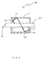
- FIGS 1-4 show one embodiment of the invention.
- Assembly 10 includes housing 15, needle 45, and member 20.
- Housing 15 has a proximal end and a distal end. Additionally, housing 15 has opposing sides that are connected to the proximal and distal ends.
- Member 20 is comprised of a flexible material such as stainless steel shunt stock that allows member 20 to be bent by a variety of methods including using a die to press on member 20 to form an angle at various points in member 20.
- Member 20 has at least two points in which member 20 is angled. These angles may range from approximately 20° to 90°.
- the angled points in member 20 are represented by first contact point 30 and second contact point 40.
- first contact point 30 and second contact point 40 at different points of the inner surface of housing 15, one embodiment of the invention is able to provide greater stability for holding needle 45 securely in place prior to, during, and after the insertion of needle 45 into a patient.
- third contact point 25 and fourth contact point 35 between member 20 and housing 15 provide additional support for securely holding needle 45 in place.
- Member 20 further has aperture 42 to receive needle 45. Although it is shown that aperture 42 is substantially centrally located in member 20, it will be appreciated that other configurations are also useful to practice the invention. For example, member 20 may have a plurality of angled points that allow member 20 to have more than one location to receive needle 45.
- Figure 1 and 3 illustrate member 20 in an unlocked position in which needle 45 extends through housing 15 to X 1 . Needle 45 is in the unlocked position during insertion of needle 45 into the patient and while needle 45 is in the patient. The distal and proximal end of member 20 lays against member 20. While the distal end of member 20 is adjacent to member 20, needle 45 is capable of moving within aperture 100 of member 20.
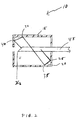
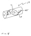
- Figure 2 illustrates a cross-sectional view and Figure 4 shows an isometric view of the locked position at X 2 of member 20.
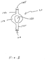
- Figure 5 shows an enlarged sectional view of a member used in accordance with one embodiment of the invention.
- Figure 5 shows that wall 150 forms aperture 100.
- aperture 100 is shown to have a top portion that is substantially circular in shape and a lower portion that is substantially elliptical in shape, other shapes may also be used.
- aperture 100 may be circular, . rectangular, egg-shaped, or any other suitable shape for securely holding member 20. Needle 45 slides through the large portion of aperture 100 while needle 45 is in the unlocked position shown in Figure 1 and 3 .
- first arm 140 and second arm 125 Protruding from wall 150 is first arm 140 and second arm 125. Extending at the distal end of first arm 140 is first recess region 105 and extending from second arm 125 is second recess region 110. These recessed regions may also be referred to as indentations and are used to contact the outer surface of needle 45 or alternatively, contact the inner surface of housing 15. Member 20 is generally greater in length than housing 15 to allow for tension to exist in member 20 when it is forced to conform to the inner dimensions of housing 15 which thereby increases the pressure against housing 15.
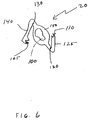
- Figure 6 shows an isometric view of member 20.
- Wall 150 forms aperture 100.
- First arm 140 and second arm 125 are shown to be at opposing angles. Therefore, first arm 140 may point in the proximal direction of housing 15 (not shown) and second arm 125 may point in the direction of the distal end of housing 15 (not shown).
- First angle 120 and second angle 130 of the first and second arm generally have an angle at approximately within 10° of each other but different angles may also be accomodated.
- Distally-directed forces exerted on member 20 will cause an initial sliding movement of the entire assembly 10 ( Figure 1 ) without separating member 20 from housing 15. Continued exertion of a distally-directed axial force on member 20 after member 20 is locked in place with needle 45 will cause no further advancement of needle 45. Accordingly, the claimed invention offers an advantage over the prior art since the amount of force required to dislodge the device is so great that the device in its entirety would likely be destroyed.
Landscapes
- Health & Medical Sciences (AREA)
- Engineering & Computer Science (AREA)
- General Health & Medical Sciences (AREA)
- Public Health (AREA)
- Anesthesiology (AREA)
- Biomedical Technology (AREA)
- Heart & Thoracic Surgery (AREA)
- Hematology (AREA)
- Life Sciences & Earth Sciences (AREA)
- Animal Behavior & Ethology (AREA)
- Environmental & Geological Engineering (AREA)
- Vascular Medicine (AREA)
- Veterinary Medicine (AREA)
- Infusion, Injection, And Reservoir Apparatuses (AREA)
- Portable Nailing Machines And Staplers (AREA)
- Measurement Of The Respiration, Hearing Ability, Form, And Blood Characteristics Of Living Organisms (AREA)
- Electrical Discharge Machining, Electrochemical Machining, And Combined Machining (AREA)
- Knitting Machines (AREA)
- Harvesting Machines For Specific Crops (AREA)
- Electronic Switches (AREA)
- Impact Printers (AREA)
Abstract
Description
- This invention relates generally to medical devices and more particularly to a needle safety device for safely closing a needle up a catheter.
- Intravascular devices such as catheter assemblies are generally used for passing fluids between a device such as a syringe or a drip to or from body lumens such as veins or arteries, or other internal target sites. Such an assembly usually includes a hub, a catheter tube, and a needle. An eyelet ring is typically inserted into the catheter. The catheter tube, together with the eyelet ring, is then inserted into an opening in the nose of the hub and is secured to the hub by press fitting the eyelet ring within the nose of the hub. This hub and tube assembly is then mounted over a sharp needle which is in turn attached to a plastic hub. The sharp tip of the needle is used for piercing a body lumen so that access may be gained into the body lumen by the needle and subsequently the catheter. Once the catheter and the needle are located within the body lumen, the needle is removed and discarded while the catheter tube remains in the body lumen. A syringe or a tube of a drip is then attached to the hub so that fluids may be passed through the hub and the catheter between the drip or the syringe and the body lumen. The hub is typically made of materials that provide sufficient rigidity to securely attach drip lines thereto and the catheter tube is usually made of a material which is flexible and soft to minimize bodily injury.
- To prevent the used sharpened distal tip of a needle from inadvertently piercing the skin of a healthcare worker, a cover may be used in conjunction with an inner shield to cover the needle. U.S. Patent No. 5,344,408, issued to Partika (Partika) represents an example of a device used in the art. In Partika, levers and teeth secure the needle such that the needle does not extend outside of a housing. More particularly, one lever arm is configured with an aperture for receiving the needle and the distal end of the lever arm contacts the inner surface of the housing. However, this assembly is not stable since the lever arm contacts only one point of the assembly. The assembly may become detached if a force is applied to the proximal end of the lever arm. It is therefore desirable to have an assembly that increases the stability of the needle within a housing to prevent dislodgement of the assembly.
- Another needle tip protection device is disclosed in WO 99/08742 It comprises the features of the preamble of
claim 1 appended hereto. A housing for a spring clip is provided by the catheter hub. Upon retracting the needle from the hub , the spring clip secures over the needle tip and exits the hub on the needle tip , thereby protecting the needle tip from accidental needle sticks. - The present invention provides a method of forming a needle safety device as defined in claim 11 and a needle safety device as defined in claim, 1 , the needle safety device comprising a needle having a proximal and a distal end, a flexible member having a proximal and distal end and an aperture to receive the needle, and a housing. The proximal and distal end of the flexible member contacts the housing at a first point located near the proximal end of the housing and at a second point located near the distal end of the housing. Additional features, embodiments, and benefits will be evident in view of the figures and detailed description presented herein.
- The accompanying drawings are included to provide a further understanding of the invention, and are incorporated in and constitute a part of this specification. The drawings illustrate embodiments of the invention and, together with the description, serve to explain the principles of the invention.
- Figure 1 is a cross-sectional view of an embodiment of the invention wherein a member is in an unlocked position.
- Figure 2 is a cross-sectional view of an embodiment of the invention wherein the member is in a locked position.
- Figure 3 is an isometric view of an embodiment of the invention wherein a member is in a locked position.
- Figure 4 is an isometric view of an embodiment of the invention wherein a member is in a locked position.
- Figure 5 is an enlarged sectional view of a member used in accordance with one embodiment of the present invention.
- Figure 6 is an isometric view of the member of Figure 1 in accordance with one embodiment of the invention.
-
- A method and an apparatus for securing a needle safety device assembly is disclosed. In the following description, numerous specific details are set forth in order to provide a more thorough understanding of the present invention. It will be apparent, however, to one skilled in the art, that the present invention may be practiced without employing these specific details. In other instances, well known processes and processing techniques have not been described in detail in order to avoid unnecessarily obscuring the present invention.
- Figures 1-4 show one embodiment of the invention.
Assembly 10 includeshousing 15,needle 45, andmember 20.Housing 15 has a proximal end and a distal end. Additionally,housing 15 has opposing sides that are connected to the proximal and distal ends.Member 20 is comprised of a flexible material such as stainless steel shunt stock that allowsmember 20 to be bent by a variety of methods including using a die to press onmember 20 to form an angle at various points inmember 20.Member 20 has at least two points in whichmember 20 is angled. These angles may range from approximately 20° to 90°. The angled points inmember 20 are represented byfirst contact point 30 andsecond contact point 40. It will be appreciated that by havingfirst contact point 30 andsecond contact point 40 at different points of the inner surface ofhousing 15, one embodiment of the invention is able to provide greater stability for holdingneedle 45 securely in place prior to, during, and after the insertion ofneedle 45 into a patient. In addition to first and second contact points (30, 40),third contact point 25 andfourth contact point 35 betweenmember 20 andhousing 15 provide additional support for securely holdingneedle 45 in place. -
Member 20 further hasaperture 42 to receiveneedle 45. Although it is shown thataperture 42 is substantially centrally located inmember 20, it will be appreciated that other configurations are also useful to practice the invention. For example,member 20 may have a plurality of angled points that allowmember 20 to have more than one location to receiveneedle 45. - Figure 1 and 3
illustrate member 20 in an unlocked position in whichneedle 45 extends throughhousing 15 to X1.Needle 45 is in the unlocked position during insertion ofneedle 45 into the patient and whileneedle 45 is in the patient. The distal and proximal end ofmember 20 lays againstmember 20. While the distal end ofmember 20 is adjacent tomember 20,needle 45 is capable of moving withinaperture 100 ofmember 20. - Figure 2 illustrates a cross-sectional view and Figure 4 shows an isometric view of the locked position at X2 of
member 20. Onceneedle 45 is removed from the patient and the catheter (not shown), the distal end ofmember 20 contacts the beveled end ofneedle 45 afterneedle 45 slides out of the catheter (not shown). When the distal end ofmember 20 contacts the beveled tip ofneedle 45, a clicking or snapping noise is produced. This noise indicates to the healthcare worker thatneedle 45 is securely in place withinhousing 15 and that the healthcare worker is safe from inadvertently piercing his or her skin by the used needle. - Figure 5 shows an enlarged sectional view of a member used in accordance with one embodiment of the invention. Figure 5 shows that
wall 150forms aperture 100. Althoughaperture 100 is shown to have a top portion that is substantially circular in shape and a lower portion that is substantially elliptical in shape, other shapes may also be used. For example,aperture 100 may be circular, . rectangular, egg-shaped, or any other suitable shape for securely holdingmember 20.Needle 45 slides through the large portion ofaperture 100 whileneedle 45 is in the unlocked position shown in Figure 1 and 3. - Protruding from
wall 150 isfirst arm 140 andsecond arm 125. Extending at the distal end offirst arm 140 isfirst recess region 105 and extending fromsecond arm 125 issecond recess region 110. These recessed regions may also be referred to as indentations and are used to contact the outer surface ofneedle 45 or alternatively, contact the inner surface ofhousing 15.Member 20 is generally greater in length thanhousing 15 to allow for tension to exist inmember 20 when it is forced to conform to the inner dimensions ofhousing 15 which thereby increases the pressure againsthousing 15. - Figure 6 shows an isometric view of
member 20.Wall 150forms aperture 100.First arm 140 andsecond arm 125 are shown to be at opposing angles. Therefore,first arm 140 may point in the proximal direction of housing 15 (not shown) andsecond arm 125 may point in the direction of the distal end of housing 15 (not shown).First angle 120 andsecond angle 130 of the first and second arm generally have an angle at approximately within 10° of each other but different angles may also be accomodated. - Distally-directed forces exerted on
member 20 will cause an initial sliding movement of the entire assembly 10 (Figure 1) without separatingmember 20 fromhousing 15. Continued exertion of a distally-directed axial force onmember 20 aftermember 20 is locked in place withneedle 45 will cause no further advancement ofneedle 45. Accordingly, the claimed invention offers an advantage over the prior art since the amount of force required to dislodge the device is so great that the device in its entirety would likely be destroyed. - In the preceding detailed description, the invention is described with reference to specific embodiments thereof. It will, however, be evident that various modifications and changes may be made thereto without departing from the scope of the invention as set forth in the claims. The specification and drawings are, accordingly, to be regarded in an illustrative rather than a restrictive sense.
Claims (15)
- A needle safety device comprising:characterized in that:a needle (45) having a proximal end and a distal end,a housing (15) through which the needle passes, the needle (45) having a first position in which the distal end of the needle extends outside the housing (15) and a second position in which the distal end of the needle is within the housing (15),a member (20) in the housing (15) and having an aperture (42, 100) to receive the needle (45), the member (20) contacting the housing (15) at two opposing sides of an inner surface of the housing (15), the member (20) having a proximal end and a distal end each contacting an outer surface of the needle (45) in the first position of the needle, the distal end of the member (20) blocking the distal end of the needle (45) in the second position of the needle,the member proximal and distal ends have recessed regions (105, 110) to contact the outer surface of the needle in the first position of the needle (45).
- The needle safety device of claim 1, further comprising:securing means for substantially preventing the member from moving from a first longitudinal position to a second longitudinal position.
- The needle safety device of any preceding claim, wherein the distal end of the member (20) contacts the inner surface of the housing at a contact point (30, 40) located near the distal end of the housing (15).
- The needle safety device of any preceding claim, wherein the proximal end of the member contacts the inner surface of the housing at a contact point (35, 25) located near a proximal end of the housing (15).
- The needle safety device of claim 3 or claim 4, wherein the member is angled at the point of contact approximately in the range of 20° to 90°.
- The needle safety device of any preceding claim, wherein the member (20) has a substantially Z-shape.
- The needle safety device of any preceding claim, wherein the member (20) is slidably disposed over the needle (45).
- The needle safety device of any preceding claim, the member (20) including a distal arm (140) and a proximal arm (125) at the respective distal and proximal ends of the member, the recessed regions (105, 110) being on the arms (105, 110).
- The needle safety device of any preceding claim, wherein the member (20) is flexible.
- The needle safety device of any preceding claim, wherein the aperture (42) is a hole (100).
- A method of forming a needle safety device comprising:characterized by:placing a member with a proximal end, a distal end, and an aperture therebetween into a housing such that the proximal and distal ends of the member contact the housing at two opposing sides of the housing;disposing a needle with a proximal end and a distal tip through the aperture of the member and through the housing such that the distal tip of the needle extends outside the housing and an outer surface of the needle is in contact with each of the proximal and distal ends of the member such when the needle distal tip is withdrawn into the housing, the member distal end blocks the needle distal tip,a recessed region at each of the proximal and distal ends of the member andwhen the needle distal tip extends outside the housing, the outer surface of the needle is in contact with the recessed regions.
- The method of claim 11, wherein the member forms at least one angle approximately in the range of 20° to 90°.
- The method of claim 11 or claim 12, wherein the member is slidably disposed over the needle.
- The method of any of claims 11 through 13, wherein the flexible member has a substantially Z-shape.
- The method of any of claims 11 through 14 wherein the member is flexible.
Applications Claiming Priority (2)
| Application Number | Priority Date | Filing Date | Title |
|---|---|---|---|
| US472353 | 1990-01-30 | ||
| US09/472,353 US6406459B1 (en) | 1999-12-21 | 1999-12-21 | Needle safety device |
Publications (2)
| Publication Number | Publication Date |
|---|---|
| EP1110571A1 EP1110571A1 (en) | 2001-06-27 |
| EP1110571B1 true EP1110571B1 (en) | 2005-04-27 |
Family
ID=23875176
Family Applications (1)
| Application Number | Title | Priority Date | Filing Date |
|---|---|---|---|
| EP00311424A Expired - Lifetime EP1110571B1 (en) | 1999-12-21 | 2000-12-20 | Needle safety device |
Country Status (16)
| Country | Link |
|---|---|
| US (1) | US6406459B1 (en) |
| EP (1) | EP1110571B1 (en) |
| JP (1) | JP4250330B2 (en) |
| AT (1) | ATE294003T1 (en) |
| BR (1) | BR0007357B1 (en) |
| CA (1) | CA2328798C (en) |
| CO (1) | CO5280220A1 (en) |
| CY (1) | CY1105668T1 (en) |
| DE (1) | DE60019709T2 (en) |
| DK (1) | DK1110571T3 (en) |
| ES (1) | ES2239578T3 (en) |
| MX (1) | MXPA01000073A (en) |
| PT (1) | PT1110571E (en) |
| SG (1) | SG93919A1 (en) |
| TW (1) | TW559563B (en) |
| ZA (1) | ZA200007716B (en) |
Cited By (1)
| Publication number | Priority date | Publication date | Assignee | Title |
|---|---|---|---|---|
| US8845584B2 (en) | 2001-03-15 | 2014-09-30 | Specialized Health Products, Inc. | Safety shield for medical needles |
Families Citing this family (36)
| Publication number | Priority date | Publication date | Assignee | Title |
|---|---|---|---|---|
| US6749588B1 (en) * | 1998-04-09 | 2004-06-15 | Becton Dickinson And Company | Catheter and introducer needle assembly with needle shield |
| US6902546B2 (en) | 2001-03-15 | 2005-06-07 | Specialized Health Products, Inc. | Safety shield for medical needles |
| US7004927B2 (en) * | 2001-03-15 | 2006-02-28 | Specialized Health Products, Inc. | Safety shield for medical needles |
| US6984213B2 (en) * | 2001-03-15 | 2006-01-10 | Specialized Health Products, Inc. | Biopsy needle device |
| US6595955B2 (en) | 2001-03-15 | 2003-07-22 | Specialized Health Products, Inc. | Safety shield for medical needles |
| US7179244B2 (en) * | 2001-03-15 | 2007-02-20 | Specialized Health Products, Inc. | Resettable safety shield for medical needles |
| US6796962B2 (en) * | 2001-03-15 | 2004-09-28 | Specialized Health Products, Inc. | Safety shield for medical needles |
| ES2382227T3 (en) * | 2002-06-20 | 2012-06-06 | Becton, Dickinson And Company | Catheter and introducer needle assembly with needle guard |
| US7458954B2 (en) * | 2002-11-07 | 2008-12-02 | Specialized Health Products, Inc. | Safety shield for medical needles |
| US7226434B2 (en) | 2003-10-31 | 2007-06-05 | Tyco Healthcare Group Lp | Safety shield |
| US7988664B2 (en) * | 2004-11-01 | 2011-08-02 | Tyco Healthcare Group Lp | Locking clip with trigger bushing |
| EP1696979B1 (en) * | 2003-11-25 | 2012-08-08 | Specialized Health Products Inc. | Resettable safety shield for medical needles |
| US7662134B2 (en) * | 2004-02-12 | 2010-02-16 | Miller Stuart H | Needle stick protection device |
| US7207975B2 (en) * | 2004-02-12 | 2007-04-24 | Miller Stuart H | Needle stick protection device |
| US7513888B2 (en) * | 2004-02-17 | 2009-04-07 | Smiths Medical Asd, Inc. | Needle guards |
| US7905857B2 (en) | 2005-07-11 | 2011-03-15 | Covidien Ag | Needle assembly including obturator with safety reset |
| US7828773B2 (en) | 2005-07-11 | 2010-11-09 | Covidien Ag | Safety reset key and needle assembly |
| US7850650B2 (en) | 2005-07-11 | 2010-12-14 | Covidien Ag | Needle safety shield with reset |
| US20060276747A1 (en) | 2005-06-06 | 2006-12-07 | Sherwood Services Ag | Needle assembly with removable depth stop |
| US7731692B2 (en) | 2005-07-11 | 2010-06-08 | Covidien Ag | Device for shielding a sharp tip of a cannula and method of using the same |
| US7654735B2 (en) | 2005-11-03 | 2010-02-02 | Covidien Ag | Electronic thermometer |
| JP4994775B2 (en) | 2006-10-12 | 2012-08-08 | 日本コヴィディエン株式会社 | Needle point protector |
| WO2009042874A1 (en) * | 2007-09-27 | 2009-04-02 | Tyco Healthcare Group Lp | I.v. catheter assembly and needle safety device |
| US8357104B2 (en) | 2007-11-01 | 2013-01-22 | Coviden Lp | Active stylet safety shield |
| CA2705990C (en) | 2007-11-21 | 2016-11-08 | Becton, Dickinson And Company | Needle safety device |
| US8298180B2 (en) * | 2007-11-21 | 2012-10-30 | Becton, Dickinson And Company | Safety needle guard |
| DE602008002806D1 (en) | 2007-12-20 | 2010-11-11 | Tyco Healthcare | Locking cap arrangement with spring-loaded collar |
| DE202009009119U1 (en) * | 2009-07-02 | 2009-12-31 | B. Braun Melsungen Ag | Protection device for a hypodermic needle |
| US9289579B2 (en) * | 2009-09-22 | 2016-03-22 | Poly Medicure Limited | Needle tip guard |
| US9238104B2 (en) | 2011-02-28 | 2016-01-19 | Injectimed, Inc. | Needle guard |
| US8764711B2 (en) | 2011-02-28 | 2014-07-01 | Injectimed, Inc. | Needle guard |
| EP2517751B8 (en) | 2011-04-27 | 2018-02-28 | Kpr U.S., Llc | Safety IV catheter assemblies |
| WO2013048975A1 (en) | 2011-09-26 | 2013-04-04 | Covidien Lp | Safety catheter |
| EP2760521B1 (en) | 2011-09-26 | 2016-01-06 | Covidien LP | Safety iv catheter and needle assembly |
| WO2013056223A1 (en) | 2011-10-14 | 2013-04-18 | Covidien Lp | Safety iv catheter assembly |
| JP6883577B2 (en) * | 2015-11-19 | 2021-06-09 | ノボ・ノルデイスク・エー/エス | Shielded needle cannula |
Family Cites Families (8)
| Publication number | Priority date | Publication date | Assignee | Title |
|---|---|---|---|---|
| US5662610A (en) * | 1989-02-01 | 1997-09-02 | Sircom; Richard C. | Automatic needle guard tip protection |
| US5053017A (en) * | 1990-02-28 | 1991-10-01 | Chamuel Steven R | Hypodermic needle safety clip |
| US5549570A (en) * | 1993-01-27 | 1996-08-27 | Rogalsky; Alena | Medical needle unit |
| US5344408A (en) | 1993-08-06 | 1994-09-06 | Becton, Dickinson And Company | Break-away safety shield for needle cannula |
| US5584810A (en) | 1995-07-11 | 1996-12-17 | Becton Dickinson And Company | Needle point guard assembly |
| US6117108A (en) | 1997-08-20 | 2000-09-12 | Braun Melsungen Ag | Spring clip safety IV catheter |
| US6280419B1 (en) * | 1999-08-09 | 2001-08-28 | Arrow International, Inc. | Hypodermic needle guard |
| US6210373B1 (en) * | 1999-12-30 | 2001-04-03 | Ethicon, Inc. | Needle safety cover |
-
1999
- 1999-12-21 US US09/472,353 patent/US6406459B1/en not_active Expired - Lifetime
-
2000
- 2000-12-19 CA CA002328798A patent/CA2328798C/en not_active Expired - Fee Related
- 2000-12-20 AT AT00311424T patent/ATE294003T1/en not_active IP Right Cessation
- 2000-12-20 DK DK00311424T patent/DK1110571T3/en active
- 2000-12-20 PT PT00311424T patent/PT1110571E/en unknown
- 2000-12-20 ZA ZA200007716A patent/ZA200007716B/en unknown
- 2000-12-20 EP EP00311424A patent/EP1110571B1/en not_active Expired - Lifetime
- 2000-12-20 ES ES00311424T patent/ES2239578T3/en not_active Expired - Lifetime
- 2000-12-20 DE DE60019709T patent/DE60019709T2/en not_active Expired - Lifetime
- 2000-12-20 JP JP2000387733A patent/JP4250330B2/en not_active Expired - Fee Related
- 2000-12-20 SG SG200007568A patent/SG93919A1/en unknown
- 2000-12-21 CO CO00097139A patent/CO5280220A1/en not_active Application Discontinuation
- 2000-12-21 BR BRPI0007357-1A patent/BR0007357B1/en not_active IP Right Cessation
-
2001
- 2001-01-08 MX MXPA01000073A patent/MXPA01000073A/en active IP Right Grant
- 2001-06-26 TW TW089127306A patent/TW559563B/en not_active IP Right Cessation
-
2005
- 2005-07-08 CY CY20051100830T patent/CY1105668T1/en unknown
Cited By (1)
| Publication number | Priority date | Publication date | Assignee | Title |
|---|---|---|---|---|
| US8845584B2 (en) | 2001-03-15 | 2014-09-30 | Specialized Health Products, Inc. | Safety shield for medical needles |
Also Published As
| Publication number | Publication date |
|---|---|
| TW559563B (en) | 2003-11-01 |
| US6406459B1 (en) | 2002-06-18 |
| SG93919A1 (en) | 2003-01-21 |
| JP4250330B2 (en) | 2009-04-08 |
| CA2328798C (en) | 2007-12-11 |
| BR0007357A (en) | 2001-10-09 |
| MXPA01000073A (en) | 2002-11-04 |
| DK1110571T3 (en) | 2005-07-11 |
| ATE294003T1 (en) | 2005-05-15 |
| CY1105668T1 (en) | 2010-12-22 |
| DE60019709T2 (en) | 2006-01-19 |
| ES2239578T3 (en) | 2005-10-01 |
| ZA200007716B (en) | 2002-06-20 |
| JP2001314504A (en) | 2001-11-13 |
| CA2328798A1 (en) | 2001-06-21 |
| EP1110571A1 (en) | 2001-06-27 |
| BR0007357B1 (en) | 2009-01-13 |
| DE60019709D1 (en) | 2005-06-02 |
| PT1110571E (en) | 2005-07-29 |
| CO5280220A1 (en) | 2003-05-30 |
Similar Documents
| Publication | Publication Date | Title |
|---|---|---|
| EP1110571B1 (en) | Needle safety device | |
| JP5669730B2 (en) | Device for deflecting the needle safely | |
| US6673047B2 (en) | Blood collection set | |
| JP5221354B2 (en) | Needle retraction structure | |
| US5501675A (en) | Safety catheter assembly having safety stop push button | |
| US5911705A (en) | One step catheter advancement automatic needle retraction system | |
| EP0824925B1 (en) | Catheter insertion needle with protective sheath | |
| EP1113837B1 (en) | Catheter introducer with clamping wings | |
| US7422573B2 (en) | Forward blunting wingset with leaf spring driven shield | |
| EP0931561A2 (en) | Medical devices | |
| EP2810681A1 (en) | Vascular acess assembly and safety device | |
| EP0753316A1 (en) | Lockable needle point guard | |
| JP2005533617A (en) | Safety shield for medical needle | |
| NZ233246A (en) | Catheter assembly with slideable needle guard and flash chamber | |
| JP2003180833A (en) | Safe catheter | |
| JP2009131655A (en) | Catheter introducer assembly having safety sealed needle | |
| JP2010099534A (en) | Compact needle point shield | |
| EP1292355B1 (en) | Catheter and introducer needle assembly with needle shield | |
| WO2018089385A1 (en) | Needle cover apparatus | |
| US7377911B2 (en) | Medical needle device with winged shield for erroneous piercing prevention | |
| EP0808634B1 (en) | Medical device with means protecting against inadvertent needle-stick | |
| KR101703753B1 (en) | Needle stick guard, and puncturing kit including such a needle stick guard | |
| CA2097659A1 (en) | Catheter with needle guard and extended flash chamber | |
| AU772060B2 (en) | Needle safety device | |
| CA2364972A1 (en) | Blood collection set |
Legal Events
| Date | Code | Title | Description |
|---|---|---|---|
| PUAI | Public reference made under article 153(3) epc to a published international application that has entered the european phase |
Free format text: ORIGINAL CODE: 0009012 |
|
| AK | Designated contracting states |
Kind code of ref document: A1 Designated state(s): AT BE CH CY DE DK ES FI FR GB GR IE IT LI LU MC NL PT SE TR |
|
| AX | Request for extension of the european patent |
Free format text: AL;LT;LV;MK;RO;SI |
|
| 17P | Request for examination filed |
Effective date: 20011203 |
|
| AKX | Designation fees paid |
Free format text: AT BE CH CY DE DK ES FI FR GB GR IE IT LI LU MC NL PT SE TR |
|
| 17Q | First examination report despatched |
Effective date: 20040126 |
|
| GRAP | Despatch of communication of intention to grant a patent |
Free format text: ORIGINAL CODE: EPIDOSNIGR1 |
|
| GRAS | Grant fee paid |
Free format text: ORIGINAL CODE: EPIDOSNIGR3 |
|
| GRAA | (expected) grant |
Free format text: ORIGINAL CODE: 0009210 |
|
| RAP1 | Party data changed (applicant data changed or rights of an application transferred) |
Owner name: MEDEX, INC. |
|
| AK | Designated contracting states |
Kind code of ref document: B1 Designated state(s): AT BE CH CY DE DK ES FI FR GB GR IE IT LI LU MC NL PT SE TR |
|
| REG | Reference to a national code |
Ref country code: GB Ref legal event code: FG4D |
|
| REG | Reference to a national code |
Ref country code: CH Ref legal event code: EP |
|
| REG | Reference to a national code |
Ref country code: IE Ref legal event code: FG4D |
|
| REF | Corresponds to: |
Ref document number: 60019709 Country of ref document: DE Date of ref document: 20050602 Kind code of ref document: P |
|
| REG | Reference to a national code |
Ref country code: DK Ref legal event code: T3 |
|
| REG | Reference to a national code |
Ref country code: GR Ref legal event code: EP Ref document number: 20050401830 Country of ref document: GR |
|
| REG | Reference to a national code |
Ref country code: CH Ref legal event code: NV Representative=s name: PATENTANWAELTE SCHAAD, BALASS, MENZL & PARTNER AG |
|
| REG | Reference to a national code |
Ref country code: PT Ref legal event code: SC4A Effective date: 20050513 |
|
| REG | Reference to a national code |
Ref country code: SE Ref legal event code: TRGR |
|
| REG | Reference to a national code |
Ref country code: ES Ref legal event code: FG2A Ref document number: 2239578 Country of ref document: ES Kind code of ref document: T3 |
|
| PG25 | Lapsed in a contracting state [announced via postgrant information from national office to epo] |
Ref country code: MC Free format text: LAPSE BECAUSE OF NON-PAYMENT OF DUE FEES Effective date: 20051231 Ref country code: LU Free format text: LAPSE BECAUSE OF NON-PAYMENT OF DUE FEES Effective date: 20051231 |
|
| PLBE | No opposition filed within time limit |
Free format text: ORIGINAL CODE: 0009261 |
|
| STAA | Information on the status of an ep patent application or granted ep patent |
Free format text: STATUS: NO OPPOSITION FILED WITHIN TIME LIMIT |
|
| ET | Fr: translation filed | ||
| 26N | No opposition filed |
Effective date: 20060130 |
|
| PGFP | Annual fee paid to national office [announced via postgrant information from national office to epo] |
Ref country code: DK Payment date: 20071215 Year of fee payment: 8 |
|
| PGFP | Annual fee paid to national office [announced via postgrant information from national office to epo] |
Ref country code: GR Payment date: 20071116 Year of fee payment: 8 |
|
| PGFP | Annual fee paid to national office [announced via postgrant information from national office to epo] |
Ref country code: CH Payment date: 20081230 Year of fee payment: 9 |
|
| PGFP | Annual fee paid to national office [announced via postgrant information from national office to epo] |
Ref country code: AT Payment date: 20081211 Year of fee payment: 9 Ref country code: FI Payment date: 20081212 Year of fee payment: 9 Ref country code: PT Payment date: 20081215 Year of fee payment: 9 |
|
| PGFP | Annual fee paid to national office [announced via postgrant information from national office to epo] |
Ref country code: BE Payment date: 20090119 Year of fee payment: 9 Ref country code: CY Payment date: 20081126 Year of fee payment: 9 |
|
| REG | Reference to a national code |
Ref country code: DK Ref legal event code: EBP |
|
| PG25 | Lapsed in a contracting state [announced via postgrant information from national office to epo] |
Ref country code: DK Free format text: LAPSE BECAUSE OF NON-PAYMENT OF DUE FEES Effective date: 20090105 |
|
| PG25 | Lapsed in a contracting state [announced via postgrant information from national office to epo] |
Ref country code: GR Free format text: LAPSE BECAUSE OF NON-PAYMENT OF DUE FEES Effective date: 20090703 |
|
| REG | Reference to a national code |
Ref country code: PT Ref legal event code: MM4A Free format text: LAPSE DUE TO NON-PAYMENT OF FEES Effective date: 20100621 |
|
| BERE | Be: lapsed |
Owner name: *MEDEX INC. Effective date: 20091231 |
|
| PG25 | Lapsed in a contracting state [announced via postgrant information from national office to epo] |
Ref country code: PT Free format text: LAPSE BECAUSE OF NON-PAYMENT OF DUE FEES Effective date: 20100621 |
|
| REG | Reference to a national code |
Ref country code: CH Ref legal event code: PL |
|
| PG25 | Lapsed in a contracting state [announced via postgrant information from national office to epo] |
Ref country code: AT Free format text: LAPSE BECAUSE OF NON-PAYMENT OF DUE FEES Effective date: 20091220 Ref country code: FI Free format text: LAPSE BECAUSE OF NON-PAYMENT OF DUE FEES Effective date: 20091220 |
|
| PG25 | Lapsed in a contracting state [announced via postgrant information from national office to epo] |
Ref country code: LI Free format text: LAPSE BECAUSE OF NON-PAYMENT OF DUE FEES Effective date: 20091231 Ref country code: CY Free format text: LAPSE BECAUSE OF NON-PAYMENT OF DUE FEES Effective date: 20091220 Ref country code: CH Free format text: LAPSE BECAUSE OF NON-PAYMENT OF DUE FEES Effective date: 20091231 Ref country code: BE Free format text: LAPSE BECAUSE OF NON-PAYMENT OF DUE FEES Effective date: 20091231 |
|
| PG25 | Lapsed in a contracting state [announced via postgrant information from national office to epo] |
Ref country code: TR Free format text: LAPSE BECAUSE OF NON-PAYMENT OF DUE FEES Effective date: 20100921 |
|
| PGFP | Annual fee paid to national office [announced via postgrant information from national office to epo] |
Ref country code: TR Payment date: 20081202 Year of fee payment: 9 |
|
| PG25 | Lapsed in a contracting state [announced via postgrant information from national office to epo] |
Ref country code: TR Free format text: LAPSE BECAUSE OF NON-PAYMENT OF DUE FEES Effective date: 20091220 |
|
| REG | Reference to a national code |
Ref country code: FR Ref legal event code: PLFP Year of fee payment: 16 |
|
| PGFP | Annual fee paid to national office [announced via postgrant information from national office to epo] |
Ref country code: IE Payment date: 20151209 Year of fee payment: 16 |
|
| PGFP | Annual fee paid to national office [announced via postgrant information from national office to epo] |
Ref country code: ES Payment date: 20151112 Year of fee payment: 16 Ref country code: NL Payment date: 20151210 Year of fee payment: 16 Ref country code: SE Payment date: 20151211 Year of fee payment: 16 |
|
| REG | Reference to a national code |
Ref country code: FR Ref legal event code: PLFP Year of fee payment: 17 |
|
| REG | Reference to a national code |
Ref country code: SE Ref legal event code: EUG |
|
| REG | Reference to a national code |
Ref country code: NL Ref legal event code: MM Effective date: 20170101 |
|
| PG25 | Lapsed in a contracting state [announced via postgrant information from national office to epo] |
Ref country code: SE Free format text: LAPSE BECAUSE OF NON-PAYMENT OF DUE FEES Effective date: 20161221 |
|
| PG25 | Lapsed in a contracting state [announced via postgrant information from national office to epo] |
Ref country code: NL Free format text: LAPSE BECAUSE OF NON-PAYMENT OF DUE FEES Effective date: 20170101 |
|
| REG | Reference to a national code |
Ref country code: IE Ref legal event code: MM4A |
|
| REG | Reference to a national code |
Ref country code: FR Ref legal event code: PLFP Year of fee payment: 18 |
|
| PG25 | Lapsed in a contracting state [announced via postgrant information from national office to epo] |
Ref country code: IE Free format text: LAPSE BECAUSE OF NON-PAYMENT OF DUE FEES Effective date: 20161220 |
|
| PGFP | Annual fee paid to national office [announced via postgrant information from national office to epo] |
Ref country code: FR Payment date: 20171113 Year of fee payment: 18 Ref country code: DE Payment date: 20171212 Year of fee payment: 18 |
|
| PGFP | Annual fee paid to national office [announced via postgrant information from national office to epo] |
Ref country code: GB Payment date: 20171220 Year of fee payment: 18 |
|
| PG25 | Lapsed in a contracting state [announced via postgrant information from national office to epo] |
Ref country code: ES Free format text: LAPSE BECAUSE OF FAILURE TO SUBMIT A TRANSLATION OF THE DESCRIPTION OR TO PAY THE FEE WITHIN THE PRESCRIBED TIME-LIMIT Effective date: 20050427 |
|
| PGFP | Annual fee paid to national office [announced via postgrant information from national office to epo] |
Ref country code: IT Payment date: 20171221 Year of fee payment: 18 |
|
| REG | Reference to a national code |
Ref country code: ES Ref legal event code: FD2A Effective date: 20181114 |
|
| RIC2 | Information provided on ipc code assigned after grant |
Ipc: A61M 5/32 20060101AFI20010328BHEP Ipc: A61M 5/50 20060101ALI20010328BHEP |
|
| PG25 | Lapsed in a contracting state [announced via postgrant information from national office to epo] |
Ref country code: ES Free format text: LAPSE BECAUSE OF FAILURE TO SUBMIT A TRANSLATION OF THE DESCRIPTION OR TO PAY THE FEE WITHIN THE PRESCRIBED TIME-LIMIT Effective date: 20161221 |
|
| REG | Reference to a national code |
Ref country code: DE Ref legal event code: R119 Ref document number: 60019709 Country of ref document: DE |
|
| GBPC | Gb: european patent ceased through non-payment of renewal fee |
Effective date: 20181220 |
|
| PG25 | Lapsed in a contracting state [announced via postgrant information from national office to epo] |
Ref country code: IT Free format text: LAPSE BECAUSE OF NON-PAYMENT OF DUE FEES Effective date: 20181220 Ref country code: FR Free format text: LAPSE BECAUSE OF NON-PAYMENT OF DUE FEES Effective date: 20181231 Ref country code: DE Free format text: LAPSE BECAUSE OF NON-PAYMENT OF DUE FEES Effective date: 20190702 |
|
| PG25 | Lapsed in a contracting state [announced via postgrant information from national office to epo] |
Ref country code: GB Free format text: LAPSE BECAUSE OF NON-PAYMENT OF DUE FEES Effective date: 20181220 |