EP2384562B1 - Management of cryptographic credentials in data processing systems - Google Patents
Management of cryptographic credentials in data processing systems Download PDFInfo
- Publication number
- EP2384562B1 EP2384562B1 EP10703121.3A EP10703121A EP2384562B1 EP 2384562 B1 EP2384562 B1 EP 2384562B1 EP 10703121 A EP10703121 A EP 10703121A EP 2384562 B1 EP2384562 B1 EP 2384562B1
- Authority
- EP
- European Patent Office
- Prior art keywords
- credential
- credentials
- accumulator
- witness
- computer
- Prior art date
- Legal status (The legal status is an assumption and is not a legal conclusion. Google has not performed a legal analysis and makes no representation as to the accuracy of the status listed.)
- Active
Links
Images


Classifications
-
- H—ELECTRICITY
- H04—ELECTRIC COMMUNICATION TECHNIQUE
- H04L—TRANSMISSION OF DIGITAL INFORMATION, e.g. TELEGRAPHIC COMMUNICATION
- H04L9/00—Cryptographic mechanisms or cryptographic arrangements for secret or secure communications; Network security protocols
- H04L9/30—Public key, i.e. encryption algorithm being computationally infeasible to invert or user's encryption keys not requiring secrecy
- H04L9/3066—Public key, i.e. encryption algorithm being computationally infeasible to invert or user's encryption keys not requiring secrecy involving algebraic varieties, e.g. elliptic or hyper-elliptic curves
- H04L9/3073—Public key, i.e. encryption algorithm being computationally infeasible to invert or user's encryption keys not requiring secrecy involving algebraic varieties, e.g. elliptic or hyper-elliptic curves involving pairings, e.g. identity based encryption [IBE], bilinear mappings or bilinear pairings, e.g. Weil or Tate pairing
-
- H—ELECTRICITY
- H04—ELECTRIC COMMUNICATION TECHNIQUE
- H04L—TRANSMISSION OF DIGITAL INFORMATION, e.g. TELEGRAPHIC COMMUNICATION
- H04L9/00—Cryptographic mechanisms or cryptographic arrangements for secret or secure communications; Network security protocols
- H04L9/32—Cryptographic mechanisms or cryptographic arrangements for secret or secure communications; Network security protocols including means for verifying the identity or authority of a user of the system or for message authentication, e.g. authorization, entity authentication, data integrity or data verification, non-repudiation, key authentication or verification of credentials
- H04L9/3218—Cryptographic mechanisms or cryptographic arrangements for secret or secure communications; Network security protocols including means for verifying the identity or authority of a user of the system or for message authentication, e.g. authorization, entity authentication, data integrity or data verification, non-repudiation, key authentication or verification of credentials using proof of knowledge, e.g. Fiat-Shamir, GQ, Schnorr, ornon-interactive zero-knowledge proofs
- H04L9/3221—Cryptographic mechanisms or cryptographic arrangements for secret or secure communications; Network security protocols including means for verifying the identity or authority of a user of the system or for message authentication, e.g. authorization, entity authentication, data integrity or data verification, non-repudiation, key authentication or verification of credentials using proof of knowledge, e.g. Fiat-Shamir, GQ, Schnorr, ornon-interactive zero-knowledge proofs interactive zero-knowledge proofs
-
- H—ELECTRICITY
- H04—ELECTRIC COMMUNICATION TECHNIQUE
- H04L—TRANSMISSION OF DIGITAL INFORMATION, e.g. TELEGRAPHIC COMMUNICATION
- H04L2209/00—Additional information or applications relating to cryptographic mechanisms or cryptographic arrangements for secret or secure communication H04L9/00
- H04L2209/12—Details relating to cryptographic hardware or logic circuitry
-
- H—ELECTRICITY
- H04—ELECTRIC COMMUNICATION TECHNIQUE
- H04L—TRANSMISSION OF DIGITAL INFORMATION, e.g. TELEGRAPHIC COMMUNICATION
- H04L2209/00—Additional information or applications relating to cryptographic mechanisms or cryptographic arrangements for secret or secure communication H04L9/00
- H04L2209/42—Anonymization, e.g. involving pseudonyms
Definitions
- This invention relates generally to management of cryptographic credentials in data processing systems.
- Methods, apparatus and computer programs are provided for use in managing a dynamic set of such credentials in data processing systems.
- a cryptographic credential is typically a cryptographic signature, certificate or other cryptographic token which is issued to a user by a trusted party (the "issuer").
- the credential can then be used subsequently in data communications between the user and another party (the “verifier", who may or may not be the issuer) as proof of the information for which the credential was issued.
- a typical scenario involves a user connecting to a remote server via a data communications network and using a credential to demonstrate authorization to access to some restricted service or other resource.
- the credential verification procedure between user and verifier often involves proving that a credential is one of a defined set of data items, for example that the credential is on a list of authentic or valid credentials.
- Such a proof may also need to be made in a manner that does not disclose the credential itself, or indeed reveal any other information about the credential or proving party so as to preserve anonymity and user privacy generally.
- the set of valid credentials is a dynamic one, changing with time as new credentials are issued and "old" credentials are removed from the set.
- the validity of a cryptographic credential may be transitory, either because it is issued for a limited time period or because it is revoked for some other reason after issuance.
- expiration date could be included in the credential (e.g. as one of the components, or "attributes", of data encrypted in the credential) and checked by a verifier to ensure validity.
- a verifier requires additional information from the issuer (or other trusted party) to confirm validity.
- Anonymous credential systems require transactions between users, issuers and verifiers to be performed in such a way that users disclose only the minimum amount of information required for a transaction to take place. Moreover, issuers cannot learn which credential attributes are shown to verifiers, and issuers and verifiers cannot link the user transactions. As anonymous credential systems are aimed at protecting user anonymity and transaction unlinkability, issuers and verifiers cannot learn certificate id's during transactions and alternative revocation status check techniques are required.
- a cryptographic accumulator allows a large set of inputs to be hashed in a single short output, namely the accumulator.
- Evidence that a given input is indeed contained in the accumulator is then provided by an accumulator witness.
- a dynamic accumulator is constructed from bilinear pairings in " Accumulators from bilinear pairings and applications", Lan Nguyen, in Alfred Menezes, editor, CT-RSA, volume 3376 of Lecture Notes in Computer Science, pages 275-292, Springer, 2005 .
- Application of this system to an anonymous credential system results in very large system parameters (a number of elements linear in the number of accumulatable values) that need to be stored by each user in order to prove validity of their credential.
- this accumulator is not secure, and that any party can succeed in an anonymous identification protocol without any secret knowledge, in " Cryptanalysis and improvement of an ID-based ad-hoc anonymous identification scheme", Zhang and Chen, at CT-RSA 05, 2005 .
- a dynamic accumulator for batch update is proposed in " A new dynamic accumulator for batch updates", Peishun Wang et al., in Sihan Qing et al., editors, ICICS, volume 4861 of Lecture Notes in Computer Science, pages 98-112, Springer, 2007 . Users who missed many witness updates can request update information to the issuer and update their witness with one multiplication. This scheme would not be usable for applications such as credential revocation however. For example, it is not apparent how one would achieve an efficient proof of knowledge of an element contained in the accumulator as is needed for use of the accumulator for revocation of credentials.
- EP 1 848 143 A1 discloses a member-certificate acquiring device which is input with a group public key and a random number and outputs a member certificate and a member secret key by communicating with a member-certificate issuing device.
- One aspect of the present invention provides a method for managing a dynamic set of cryptographic credentials in a data processing system.
- the method comprises:
- Methods embodying this invention provide fast and efficient accumulator-based techniques for managing dynamic sets of cryptographic credentials and accommodating credential revocation in data processing systems.
- witnesses are generated as the products of subsets of group elements as defined above, and this leads to exceptionally efficient witness updates.
- computation of witnesses is linear in the number of credentials in the set, and update of each witness is linear in the number of changes in the set.
- witness update can thus be achieved with a single multiplication.
- the improvement in computational complexity is such that witness updates in typical applications can be realistically handled centrally, e.g. by the issuer or one or more witness update authorities, shifting the computational burden away from users.
- This allows convenient application in data processing systems involving resource-constrained user devices such as smart cards or other devices with limited computational power.
- the system provides the basis for efficient proof protocols between users and verifiers based on anonymous credentials, and is thus eminently suitable for privacy-sensitive applications.
- the periodic generation of the cryptographic accumulator can be performed at intervals, regular or otherwise, to reflect changes in the dynamic set of credentials. At any time therefore, the accumulator should comprise the product of group elements related to the elements mapped to credentials currently in the set.
- the accumulator can be generated by calculating the defined product from the appropriate group elements for the initial set of credentials. Subsequently, however, the accumulator can be generated simply by updating the previous accumulator value via a multiplication factor to reflect the new product as detailed below.
- witnesses for an initial set of credentials can each be generated by computing the product of the appropriate subset of group elements, but updated witnesses following a change in the set can be generated by updating the previous witness via a multiplication factor as detailed below.
- witness updates are performed only when required, e.g. "on-demand" for individual users.
- witnesses are preferably generated by an authority on behalf of users as discussed above, in preferred embodiments witnesses are periodically published in the data processing system for access by users.
- each time the accumulator is generated it will typically be published immediately in the data processing system so as to be available for use by components of the system involved in subsequent credential verification processes.
- Systems might be envisaged where publication could be effected by transmitting the accumulator/witnesses directly to relevant system components. More usually, however, publication will be effected by providing access to the accumulator/witnesses via one or more data communications channels in the system, whereby system components can access the accumulator/witnesses when required for verification procedures.
- the mapping of credentials to group elements may be defined between respective group elements and a numerical identifier such as a serial number associated with each credential. This identifier is ideally defined in the credential itself. In some embodiments, the mapping might be defined by assigning the allocated group element as the identifier for the credential.
- a second aspect of the invention provides apparatus for managing a dynamic set of cryptographic credentials in a data processing system.
- the apparatus comprises control logic adapted to perform a method according to the first aspect of the invention, and memory for said plurality of group elements.
- a third aspect of the invention provides a data processing system comprising a user computer and a verifier computer each adapted for communication via a data communications network, and credential management apparatus adapted for communication with the user and verifier computers via the network.
- the credential management apparatus includes control logic adapted to perform a method according to the first aspect of the invention for managing a dynamic set of cryptographic credentials including a user credential associated with said user computer.
- the user computer stores said user credential and is adapted to acquire via said network the witness periodically generated by the credential management apparatus for the user credential.
- the user computer and verifier computer are adapted for communication via the network to implement a verification protocol proving knowledge by the user computer of a witness corresponding to a credential in the set indicated by the cryptographic accumulator.
- witness updates can be handled as separate task to other credential/accumulator management operations.
- the credential management apparatus may comprise an issuer computer adapted to periodically generate the cryptographic accumulator indicative of the set of credentials, and one or more witness update computers for periodically generating the updated witnesses for credentials on generation of the cryptographic accumulator following a change in said set.
- a fourth aspect of the invention provides a witness update computer of such a data processing system according to the third aspect of the invention.
- a fifth aspect of the invention provides a user computer of a data processing system according to the third aspect of the invention.
- a sixth aspect of the invention provides a computer program comprising program code means for causing a computer to perform a method according to the first aspect of the invention.
- computer is used herein in the most general sense and includes any device, component or system having a data processing capability for implementing a computer program.
- a computer program embodying the invention may constitute an independent program or may be an element of a larger program, and may be supplied, for example, embodied in a computer-readable medium such as a disk or an electronic transmission for loading in a computer.
- the program code means of the computer program may comprise any expression, in any language, code or notation, of a set of instructions intended to cause a computer to perform the method in question, either directly or after either or both of (a) conversion to another language, code or notation, and (b) reproduction in a different material form.
- a function ⁇ is negligible if, for every integer c, there exists an integer K such that for all k > K ,
- a problem is said to be hard (or intractable ) if there exists no probabilistic polynomial time (p.p.t.) algorithm on the size of the input to solve it.
- Security is based on the following number-theoretic assumptions.
- the accumulator construction in the embodiments to be described is based on the Diffie-Hellman Exponent assumption.
- the unforgeability of credentials is based on the Strong Diffie-Hellman assumption.
- For credential revocation we need to prove possession of an accumulator witness for a credential.
- This proof is based on our new Hidden Strong Diffie-Hellman Exponent (SDHE) assumption.
- SDHE Hidden Strong Diffie-Hellman Exponent
- n-DHE Diffie-Hellman Exponent (DHE) assumption:
- DHE Diffie-Hellman Exponent
- the n-DHE assumption states that this problem is hard to solve.
- Boneh and Boyen introduced the Strong Diffie-Hellman assumption in "Short signatures without random oracles", Dan Boneh and Xavier Boyen, in Christian Cachin and Jan Camenisch, editors, EUROCRYPT, volume 3027 of Lecture Notes in Computer Science, pages 56-73. Springer, 2004 .
- values a, ⁇ , and ⁇ denote quantities of which knowledge is being proven (and are kept secret), while all other values are known to the verifier.
- values a, ⁇ , and ⁇ denote quantities of which knowledge is being proven (and are kept secret), while all other values are known to the verifier.
- prime order groups which include all groups we consider here, it is well known that there exists a knowledge extractor which can extract these quantities from a successful prover.
- An accumulator is dynamic if the computational cost of adding/deleting elements from it is independent of the number of elements that are contained in the accumulator.
- a secure accumulator consists of algorithms AccGen, AccAdd, AccUpdate, AccWitUpdate, and AccVerify. These algorithms are used by the authority managing the accumulator (the "authority"), a user and a verifier. (In some of the preferred embodiments to be described certain of these algorithms may also be used by an untrusted update entity).
- the authority creates an accumulator key pair ( sk A , pk A ), the accumulator acc ⁇ , and a public state state ⁇ using the AccGen algorithm. It can add a new value i to the accumulator acc V using the AccAdd algorithm to obtain a new accumulator acc V ⁇ ⁇ i ⁇ and state state U ⁇ i ⁇ , together with a witness wit i .
- the accumulator for a given set of values V can be computed using the AccUpdate algorithm.
- acc V and wit i are of constant size (independent of the number of accumulated values).
- the authority does some bookkeeping about the values contained in the accumulator and the status of the accumulator when a witness wit i was created. These sets are denoted as V and V w respectively.
- the bookkeeping information is made public and is only needed for updating witnesses, it is not needed for verifying that a value is contained in an accumulator.
- the accumulator state state U also contains bookkeeping information U , the set of elements ever added to the accumulator (but not necessarily contained in the current accumulator). This is a superset of V and V w .
- AccGen(1 k , n ) creates an accumulator key pair ( sk A , pk A ), an empty accumulator acc ⁇ (for accumulating up to n values) and an initial state state ⁇ .
- AccAdd( sk A , i, acc V , state U ) allows the authority to add i to the accumulator. It outputs a new accumulator acc V ⁇ i ⁇ and state state U ⁇ i ⁇ , together with a witness wit i for i .
- AccUpdate( pk A , V, state U ) outputs an accumulator acc V for values V c U.
- AccWitUpdate( pk A , wit i , V w , acc V , V, state U ) outputs a witness wit' i for acc V if wit i was a witness for acc Vw and i ⁇ V.
- AccVerify( pk A , i, wit i , acc V ) verifies that v ⁇ V using an up-to-date witness wit i and the accumulator acc V . In that case the algorithm accepts, otherwise it rejects.
- FIG. 1 of the drawings is a simplified schematic of a first data processing system embodying the invention showing the main components involved in operation of the system.
- the data processing system 1 includes a data item management computer 2 operated by the authority responsible for managing data items, here cryptographic credentials, and for managing a cryptographic accumulator for use in the credential verification process to be described.
- this authority here the "issuer” issues cryptographic credentials to users and indicates valid credentials in the system via the accumulator to be described.
- the issuer computer 2 includes credential management logic 3 for implementing processes detailed below, memory 4 and a communications interface 5.
- the system 1 also includes a user computer 6 for using cryptographic credentials obtained from issuer computer 2, and a verifier computer 7 for verifying user credentials by reference to the accumulator to be described.
- User computer 6 includes prover logic 8 for implementing cryptographic processes described below, memory 7 and a communications interface 8.
- Verifier computer 3 includes verifier logic 11 for performing a cryptographic verification process described below, memory 12 and a communications interface 13.
- Computers 2, 6 and 7 can communicate over a data communications network 15 via their respective communications interfaces (where network 15 may in practice comprise a plurality of component networks and/or internetworks).
- the system 1 includes a distributor computer 16, shown here in network 15 and accessible to all computers 2, 6, 7, the purpose of which is explained below.
- control logic 3, 8, 11 of the issuer, user and verifier computers is configured for implementing the appropriate steps of the cryptographic processes described below.
- this control logic may be implemented in hardware or software or a combination thereof, and the precise form of the user, verifier and issuer devices 2, 6, 7 is largely irrelevant to fundamental operation of the system to be described.
- these devices are implemented by general-purpose computers, user computer 6 being a user pc and issuer and verifier computers 2, 7 being servers to which user pc 2 can connect over network 15.
- Credential management logic 3, prover logic 8 and verifier logic 11 are implemented here by respective computer programs which configure the host computers to perform the functions described. Suitable software will be apparent to those skilled in the art from the description herein.
- computers 2, 6, 7 and 16 may in general be implemented by one or more component devices.
- the functionality of user computer 6 might be distributed in practice between a general purpose computer providing a communications interface to network 15, and a separate user device such as a smart card.
- a separate user device such as a smart card.
- Such a separate device may provide secure storage for credentials and cryptographic software, and may be connected via wired or wireless links to the user computer when desired.
- Verifier computer 7 is operated by a service provider (SP).
- SP computer 7 can connect over network 15 to SP computer 7 to request access to a restricted service.
- SP computer 7 must demonstrate possession of a cryptographic credential obtained from issuer 2.
- SP computer 7 must verify that the presented credential is valid. This involves confirming that the credential is one of a set of valid credentials maintained by issuer 2. This is achieved using a cryptographic accumulator construction.
- Algorithms underlying this initial accumulator construction will be defined in the following and are based in part on the broadcast encryption scheme by Boneh, Gentry and Waters (see “ Collusion Resistant Broadcast Encryption with Short Ciphertexts and Private Keys", Boneh, Gentry and Waters, Advances in Cryptology - CRYPTO 2005, volume 3621 of Lecture Notes in Computer Science, pages 258-275, Springer, 2005 ).
- accumulator computation in the construction to be described is related to the way in which encryption keys are generated in the referenced scheme
- witness computation is related to the way in which decryption keys are generated in the referenced scheme.
- step 21 of Figure 2 logic 3 defines the mapping between group elements and the credentials to be issued.
- Each credential has an identifier in the form of serial number which is defined in the credential, and the mapping is defined between these serial numbers and respective group elements.
- serial numbers For simplicity here we represent the serial numbers by the set of integers 1 to n, though of course any arbitrary mapping of numbers to group elements can be accommodated.
- Step 22 represents generation by logic 3 of the initial set of credentials C ( i ) to be issued to users. These are the credentials that will be initially contained in the accumulator. Credentials can be generated in known manner, each credential including the respective serial number i .
- logic 3 generates the accumulator for the initial set of credentials in accordance with the following algorithm:
- the cryptographic accumulator is generated here as the product of the group elements g n +1- i for values of i for which the group element g i is mapped to a credential in the set of valid credentials.
- the group elements actually accumulated are thus related via the i -values to the elements g i mapped to valid credentials.
- the accumulator witness w is calculated as the product of a respective different subset of the group elements. This subset is dependent on the i -values of credentials in the valid set and also the i -value of the credential for which each witness is generated. Specifically, for each valid credential mapped to a group element g i , the witness comprises the product of the group elements g n +1- j + i for all values of j for which a group element g j is mapped to another valid credential. Thus, the witness generation makes use of the auxiliary group elements g n +2 , ..., g 2 n defined earlier.
- the signature ⁇ i indicates the mapping between the associated credential and the corresponding group element.
- step 25 each credential C ( i ), together with its associated witness wit i , is sent via network 15 to the user in question.
- credential logic 3 publishes the cryptographic accumulator by sending the accumulator calculated in step 23 to distributor computer(s) 16.
- Distributor 16 publishes the accumulator on network 15 by providing access to any connecting computer 6, 7. The initial stages of accumulator setup are then complete.
- Step 30 represents the issue and revocation of credentials which occurs within a defined "epoch”.
- credential logic 3 logs this fact along with the serial number i in memory 4. While the ensuing update process could in principle be performed each time a credential is issued or revoked, the update is typically performed periodically at regular intervals, for example daily.
- credential logic 3 checks whether the current epoch has ended, and if not operation reverts to step 30.
- step 32 logic 3 updates the accumulator to account for each credential added/removed from the set of valid credentials.
- step 33 the set of witnesses is then updated by generating witnesses for newly issued credentials and updating the old witnesses for existing credentials to reflect changes in the valid set. For each newly issued credential, these processes are defined by the following algorithm:
- step 34 credential logic 3 of issuer computer 2 sends the updated accumulator and witnesses to distributor computer(s) 16 for publication on network 15.
- Trustes are published with some form of identifying tag to enable individual users to identify the witness for their particular credential when required. Operation then reverts to step 30 for the new epoch.
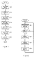
- Figure 4 illustrates the procedure when a user subsequently wishes to use his credential to access an on-line service via verifier computer 7.
- This figure indicates the key steps performed by user computer 6 on the left of the figure and verifier computer 7 on the right. Operation begins when user computer 6 connects to verifier computer 7 to request access to the service. Verifier logic 11 of computer 7 responds by requesting the user's credential. This request is received by prover logic 8 of user computer 6. The prover logic then establishes a connection to distributor computer 16 to download the current value of the witness w for the credential C ( i ) previously obtained from issuer 2 and stored in memory 9. This step is necessary to account for any changes in the accumulator since the credential was issued in accordance with steps 32 to 34 of Figure 3 .
- prover logic 8 sends the credential C ( i ), containing the serial number i as discussed earlier, together with the full witness wit i ( w , ⁇ i , g i ) defined above, to verifier 7.
- Verifier logic 11 then similarly accesses distributor computer 16 to download the current value of the accumulator acc V which is then stored in memory 12.
- verifier logic 11 runs the following verification protocol:
- verifier logic 11 checks that the signature ⁇ i is valid for the serial number i of the user's credential C ( i ) and the associated group element g i . (Note that the use of this signature scheme to sign the g i together with the value to which they map avoids the need to publish the mapping of the g i values, thus avoiding large public parameters during verification). Verifier logic 11 also checks that the witness w confirms the group element g i is in the current accumulator acc V . This confirms that the user's credential is valid. Verifier logic 11 then permits or denies user computer 6 access to the service according to whether or not the credential is deemed valid.
- each party can simply retrieve the new values periodically at the start of each new epoch.
- witness updates for example require only multiplications (no exponentiations) linear in the number of changes to the accumulator and do not require knowledge of any secret information. In general, therefore, witnesses could be kept up-to-date for the users either by the users themselves, by the issuer, or by some third party.
- witness updates could be performed individually by users as in prior schemes, the preferred embodiments exploit the efficiency of the system, which enables all witnesses to be feasibly kept in main memory, to allow witness calculation to be performed centrally. This is done by issuer 2 in the above embodiment.
- witness updates can be efficiently offloaded to an untrusted update entity who runs AccWitUpdate and is only given the accumulator state state U and the bookkeeping information V and V w .
- the distributor computer 16 in Figure 1 could additionally function as a witness update computer. On updating of the accumulator by issuer computer 2 following a change in the valid set, witness updates for credentials remaining in the set could be performed, altogether or in batches, by one or more such distributor computers 16.
- C Camenisch-Lysyanskaya
- IssuerKeygen(1 k ) be the certificate issuer's keypair.
- the framework supports two types of protocols: 1) an interactive certificate issuing protocol ObtainCert that allows a signature on committed values to be obtained without revealing these values and 2) efficient zero-knowledge proofs of knowledge of signature possession.
- a user can obtain a certificate on ( m 1 , ..., m l ) such that the issuer does not learn any information on the data items in H , while it learns the other data items, i.e. L ⁇ H.
- V be the set of valid certificates for an epoch with epoch information epoch V .
- a certificate is assigned a unique identifier i (embedded into it as one of the attributes) and a witness wit i .
- the user can prove to a verifier that she possesses a non-revoked certificate only if i ⁇ V . This is achieved by having the user prove that the identifier embedded into her credential is a valid one for the current epoch.
- the user needs to update her witness and both parties (the user and the verifier) need to obtain the most up-to-date epoch information epoch v for V .
- the preferred credential revocation system is based on updated IssuerKeygen and ObtainCert protocols, new algorithms UpdateEpoch and UpdateWitness for managing revocation, and a zero-knowledge proof system for a new predicate VerifyEpoch that allows proof of possession of a witness wit i :
- UpdateEpoch( V , state U ) outputs epoch information epoch V ; if V ⁇ U . Otherwise it outputs ⁇ .
- UpdateWitness( wit i , epoch V , state U ) outputs an updated witness wit' i if V ⁇ U . Otherwise it outputs ⁇ .
- a user who knows a certificate cert i and a corresponding up-to-date witness wit i can prove to a verifier possession of the certificate and its validity for the current epoch using the new predicate VerifyEpoch as follows.
- the user's secret input is cert i .
- the common input of the protocol is the issuer's public key pk I , the epoch information epoch V , and a specification of the proof statement (this includes the information revealed about the certificate).
- the user chooses to keep the first l ' messages secret while revealing the rest of the messages.
- mapping of i to g i is made implicit by including g i in the credential to make the proofs more efficient.
- the g i values are used both in the private certificate and the accumulator to represent the certificate id i . This requires that we extend the signature scheme given earlier to allow verification without knowing the secret exponent ⁇ i :
- the set up process performed by credential management logic 3 of issuer computer 2 (corresponding to step 20 of Figure 2 ) is defined by:
- each party 6, 7 downloads updated values from distributor computer 16 to account for intervening changes in the accumulator.
- prover logic 8 obtains the current witness value w i for the user's credential cred i
- verifier logic 11 sends a verification request to prover logic 6.
- prover logic defines various parameters to be used in the ensuing proof. Specifically, prover logic picks ⁇ , ⁇ ' , r, r', r'', r''' ⁇ Z q and picks opening open, open' ⁇ Z q to commit to ⁇ and r respectively.
- the prover logic then sends C , C', A, G', W', S ' and U ' to the verifier.
- the prover logic 8 and verifier logic 11 then communicate to implement a zero-knowledge (ZK) verification protocol.
- ZK zero-knowledge
- the common input of the protocol is the issuer's public key pk 1 , the epoch information epoch V , and a specification of the proof statement (this includes the information revealed about the certificate).
- the user chooses to keep the first l' messages secret while he reveals the rest of the messages:
- the above process allows the user to prove possession of a valid credential without revealing any other information to the verifier, maintaining full anonymity and transaction unlinkability.
- the system described is computationally efficient, providing, inter alia, highly efficient witness updates.
- the number of revocations per epoch is likely to be very large.
- Resource-constrained user devices will typically be unable to handle the computation required to accommodate such changes.
- witness update entities responsible for upgrading witnesses for group of users.
- witness updates could be performed by per-county or per-city. This requires only public parameters and update authorities are only responsible for correct computation of the witness updates for users in their group. Malicious behaviour by one of the witness update entities does not break system security (since they need only public parameters) but may simply lead to denial of service.
- the size of the public parameters in the foregoing construction is linear in the estimated upper bound on the number of values that may need to be accumulated. In scenarios where this upper bound is hard to estimate, over-estimation could be a costly issue.
Description
- This invention relates generally to management of cryptographic credentials in data processing systems. Methods, apparatus and computer programs are provided for use in managing a dynamic set of such credentials in data processing systems.
- A cryptographic credential is typically a cryptographic signature, certificate or other cryptographic token which is issued to a user by a trusted party (the "issuer"). The credential can then be used subsequently in data communications between the user and another party (the "verifier", who may or may not be the issuer) as proof of the information for which the credential was issued. A typical scenario involves a user connecting to a remote server via a data communications network and using a credential to demonstrate authorization to access to some restricted service or other resource. The credential verification procedure between user and verifier often involves proving that a credential is one of a defined set of data items, for example that the credential is on a list of authentic or valid credentials. Such a proof may also need to be made in a manner that does not disclose the credential itself, or indeed reveal any other information about the credential or proving party so as to preserve anonymity and user privacy generally.
- In most applications the set of valid credentials is a dynamic one, changing with time as new credentials are issued and "old" credentials are removed from the set. In particular, the validity of a cryptographic credential may be transitory, either because it is issued for a limited time period or because it is revoked for some other reason after issuance. In the former case, expiration date could be included in the credential (e.g. as one of the components, or "attributes", of data encrypted in the credential) and checked by a verifier to ensure validity. However, in the latter case where unexpected events may require early revocation (invalidation) of a credential, a verifier requires additional information from the issuer (or other trusted party) to confirm validity. For example, when a user resigns from his job, a credential allowing him to access the workplace should be invalidated. A more poignant example is the need to revoke a credit-card-like credential which has been compromised and used by malicious parties for illegal purchases. In such cases the verifier needs to check the validity of credentials with a trusted party.
- The need for verifiers to check validity of credentials raises various issues, particularly where privacy is a primary concern. In scenarios where anonymity is not an issue, an identifier such as a serial number associated with a credential can be revealed to a verifier during a transaction. The verifier could then check this against a list of revoked credential id's that is periodically published by the issuer. Another solution is for the verifier to send certificate revocation status queries to an online issuer. The former solution is communication inefficient as the list of revoked certificates can be very large, while the latter solution requires the issuing authority to be permanently online. Both solutions require knowledge of credential id's by all parties, breaking user privacy. Anonymous credential systems, however, require transactions between users, issuers and verifiers to be performed in such a way that users disclose only the minimum amount of information required for a transaction to take place. Moreover, issuers cannot learn which credential attributes are shown to verifiers, and issuers and verifiers cannot link the user transactions. As anonymous credential systems are aimed at protecting user anonymity and transaction unlinkability, issuers and verifiers cannot learn certificate id's during transactions and alternative revocation status check techniques are required.
- One known technique for addressing the above issue employs cryptographic accumulators. A cryptographic accumulator allows a large set of inputs to be hashed in a single short output, namely the accumulator. Evidence that a given input is indeed contained in the accumulator is then provided by an accumulator witness. For example, if the accumulator (ACC) is defined by F(x 1, ..., xn ) = ACC for inputs x 1 to xn , then proving that a given input x i is contained in ACC requires a witness wi and existence of a verification function V such that V(xi, wi ) = ACC. Security is assured by the feature that if xy is not contained in the accumulator, computing wy such that V(xy , wy ) = ACC is infeasible. When applied in the scenario described above, the serial numbers of all currently valid credentials are accumulated and the resulting accumulator is published. Users can then demonstrate to verifiers that their credential is still valid by using their witness to prove (in zero-knowledge) that their credential's serial number is contained in the published accumulator. Such systems have been described in: "Short group signatures", Boneh et al., in Matthew K. Franklin, editor, Advances in Cryptology — CRYPTO 2004, volume 3152 of LNCS, pages 41-55, Springer Verlag, 2004; and "Dynamic accumulators and application to efficient revocation of anonymous credentials", Camenisch and Lysyanskaya, in Moti Yung, editor, Advances in Cryptology — CRYPTO 2002, volume 2442 of LNCS, pages 61-76, Springer Verlag, 2002. A drawback of these solutions, however, is that users need to update their accumulator witnesses and an update requires at least one modular exponentiation for each newly revoked credential. Since there can be large numbers of revoked credentials in typical applications, these solutions incur a substantial computational (and communications) cost, and in particular a far greater cost than can be handled by a resource-limited user device such as a smart card. For example, the Camenisch and Lysyanskaya reference above introduces a dynamic accumulator and shows its applicability to revocation in anonymous credential systems as well as identity escrow and group signatures. Update of the proposed accumulator, as well as user witnesses, requires a number of exponentiations linear in the number of users added to or revoked from the system. This accumulator is extended, introducing witnesses and proofs that a value was not accumulated, in "Universal accumulators with efficient nonmembership proofs", Jiangtao Li et al., in Jonathan Katz and Moti Yung, editors, ACNS, volume 4521 of Lecture Notes in Computer Science, pages 253-269, Springer, 2007.
- A dynamic accumulator is constructed from bilinear pairings in "Accumulators from bilinear pairings and applications", Lan Nguyen, in Alfred Menezes, editor, CT-RSA, volume 3376 of Lecture Notes in Computer Science, pages 275-292, Springer, 2005. Application of this system to an anonymous credential system results in very large system parameters (a number of elements linear in the number of accumulatable values) that need to be stored by each user in order to prove validity of their credential. Also, it is pointed out that this accumulator is not secure, and that any party can succeed in an anonymous identification protocol without any secret knowledge, in "Cryptanalysis and improvement of an ID-based ad-hoc anonymous identification scheme", Zhang and Chen, at CT-RSA 05, 2005. Moreover, updating a witness takes one exponentiation per event and is therefore not efficient (in the paper the authors write multiplication and use addition as base operation for the algebraic group as is done sometimes in connection with bi-linear maps and elliptic curve groups (see the Nguyen reference above)).
- A dynamic accumulator for batch update is proposed in "A new dynamic accumulator for batch updates", Peishun Wang et al., in Sihan Qing et al., editors, ICICS, volume 4861 of Lecture Notes in Computer Science, pages 98-112, Springer, 2007. Users who missed many witness updates can request update information to the issuer and update their witness with one multiplication. This scheme would not be usable for applications such as credential revocation however. For example, it is not apparent how one would achieve an efficient proof of knowledge of an element contained in the accumulator as is needed for use of the accumulator for revocation of credentials.
-
EP 1 848 143 A1 - One aspect of the present invention provides a method for managing a dynamic set of cryptographic credentials in a data processing system. The method comprises:
- defining a mapping between cryptographic credentials in said set and respective group elements of a predefined plurality of group elements;
- periodically generating a cryptographic accumulator indicative of the set of credentials, the cryptographic accumulator comprising the product of respective group elements related to the group elements mapped to the credentials in the set;
- periodically publishing the cryptographic accumulator in the data processing system; and
- periodically generating a witness for each credential in the set, each witness comprising the product of a respective different subset of the group elements, the subset for each witness being dependent on the credentials in said set and the credential for which that witness is generated. The method further comprises generating the plurality of group elements. Each group element can be generated using (at least) a secret value γ and a group generator g as in the embodiments described below. More specifically, in the embodiments the group elements comprise respective elements gi = gy
i for i ∈ {1, 2, 3, ..., n} where n is a predefined maximum number of credentials in the set. (The group elements may also include additional or "auxiliary" values for use in the system as discussed below). The mapping is then defined between credentials in the set and respective group elements gi . In these embodiments, the cryptographic accumulator comprises the product of the group elements g n+1-i for values of i for which the group element gi is mapped to a credentials in said set. Thus, the elements accumulated are related via the i-values to the elements gi mapped to credentials in the set. 10. In the embodiments the group elements include auxiliary elements g n+2 = g yn+2 , g n+3 = g yn+3 , g n+4 = g yn+4 , ..., g 2n = g γ2n for use in generating witnesses. Specifically, for each credential in the set mapped to a group element gi , the witness comprises the product of the group elements g n+1-j+i for all values of j for which a group element gj is mapped to another credential in the set. - Methods embodying this invention provide fast and efficient accumulator-based techniques for managing dynamic sets of cryptographic credentials and accommodating credential revocation in data processing systems. Witnesses are generated as the products of subsets of group elements as defined above, and this leads to exceptionally efficient witness updates. In particular, computation of witnesses is linear in the number of credentials in the set, and update of each witness is linear in the number of changes in the set. Witness update can thus be achieved with a single multiplication. The improvement in computational complexity is such that witness updates in typical applications can be realistically handled centrally, e.g. by the issuer or one or more witness update authorities, shifting the computational burden away from users. This allows convenient application in data processing systems involving resource-constrained user devices such as smart cards or other devices with limited computational power. Moreover, as demonstrated by example below, the system provides the basis for efficient proof protocols between users and verifiers based on anonymous credentials, and is thus eminently suitable for privacy-sensitive applications.
- The periodic generation of the cryptographic accumulator can be performed at intervals, regular or otherwise, to reflect changes in the dynamic set of credentials. At any time therefore, the accumulator should comprise the product of group elements related to the elements mapped to credentials currently in the set. At the start of operation, the accumulator can be generated by calculating the defined product from the appropriate group elements for the initial set of credentials. Subsequently, however, the accumulator can be generated simply by updating the previous accumulator value via a multiplication factor to reflect the new product as detailed below. Similarly, witnesses for an initial set of credentials can each be generated by computing the product of the appropriate subset of group elements, but updated witnesses following a change in the set can be generated by updating the previous witness via a multiplication factor as detailed below. A new set of witnesses will typically be generated each time the accumulator is regenerated, though systems can be envisaged in which witness updates are performed only when required, e.g. "on-demand" for individual users. In any case, since witnesses are preferably generated by an authority on behalf of users as discussed above, in preferred embodiments witnesses are periodically published in the data processing system for access by users. Similarly, each time the accumulator is generated it will typically be published immediately in the data processing system so as to be available for use by components of the system involved in subsequent credential verification processes. Systems might be envisaged where publication could be effected by transmitting the accumulator/witnesses directly to relevant system components. More usually, however, publication will be effected by providing access to the accumulator/witnesses via one or more data communications channels in the system, whereby system components can access the accumulator/witnesses when required for verification procedures.
- The mapping of credentials to group elements may be defined between respective group elements and a numerical identifier such as a serial number associated with each credential. This identifier is ideally defined in the credential itself. In some embodiments, the mapping might be defined by assigning the allocated group element as the identifier for the credential.
- A second aspect of the invention provides apparatus for managing a dynamic set of cryptographic credentials in a data processing system. The apparatus comprises control logic adapted to perform a method according to the first aspect of the invention, and memory for said plurality of group elements.
- A third aspect of the invention provides a data processing system comprising a user computer and a verifier computer each adapted for communication via a data communications network, and credential management apparatus adapted for communication with the user and verifier computers via the network. The credential management apparatus includes control logic adapted to perform a method according to the first aspect of the invention for managing a dynamic set of cryptographic credentials including a user credential associated with said user computer. The user computer stores said user credential and is adapted to acquire via said network the witness periodically generated by the credential management apparatus for the user credential. The user computer and verifier computer are adapted for communication via the network to implement a verification protocol proving knowledge by the user computer of a witness corresponding to a credential in the set indicated by the cryptographic accumulator. As discussed earlier, witness updates can be handled as separate task to other credential/accumulator management operations. Hence the credential management apparatus may comprise an issuer computer adapted to periodically generate the cryptographic accumulator indicative of the set of credentials, and one or more witness update computers for periodically generating the updated witnesses for credentials on generation of the cryptographic accumulator following a change in said set. A fourth aspect of the invention provides a witness update computer of such a data processing system according to the third aspect of the invention. A fifth aspect of the invention provides a user computer of a data processing system according to the third aspect of the invention.
- A sixth aspect of the invention provides a computer program comprising program code means for causing a computer to perform a method according to the first aspect of the invention. It will be understood that the term "computer" is used herein in the most general sense and includes any device, component or system having a data processing capability for implementing a computer program. Moreover, a computer program embodying the invention may constitute an independent program or may be an element of a larger program, and may be supplied, for example, embodied in a computer-readable medium such as a disk or an electronic transmission for loading in a computer. The program code means of the computer program may comprise any expression, in any language, code or notation, of a set of instructions intended to cause a computer to perform the method in question, either directly or after either or both of (a) conversion to another language, code or notation, and (b) reproduction in a different material form.
- In general, where features are described herein with reference to an embodiment of one aspect of the invention, corresponding features may be provided in embodiments of another aspect of the invention.
- Preferred embodiments of the invention will now be described, by way of example, with reference to the accompanying drawings in which:
-
Figure 1 is a schematic illustration of a data processing system embodying the invention; -
Figure 2 indicates a setup procedure performed by an issuer computer in theFigure 1 system; -
Figure 3 indicates subsequent operation of the issuer computer ofFigure 1 ; -
Figure 4 illustrates interaction between a user computer and a verifier computer in theFigure 1 system; and -
Figure 5 illustrates interaction between a user computer and a verifier computer in a preferred implementation of theFigure 1 system. - Before describing data processing systems embodying the invention, we first present various assumptions and cryptographic tools used as building blocks which are employed in operation of the exemplary embodiments to be described.
- A function υ is negligible if, for every integer c, there exists an integer K such that for all k > K, |v(k)| < 1/kc. A problem is said to be hard (or intractable) if there exists no probabilistic polynomial time (p.p.t.) algorithm on the size of the input to solve it.
- Bilinear Pairings. Let G and GT be groups of prime order q. A map e : G × G → GT must satisfy the following properties:
- (a) Bilinearity: a map e : G×G → GT is bilinear if e(ax,by )t = e(a,b) x,y
- (b) Non-degeneracy: for all generators g, h ∈ G, e(g,h) generates GT ;
- (c) Efficiency: There exists an efficient algorithm BMGen(1 k ) that outputs (q, G, GT , e, g) to generate the bilinear map and an efficient algorithm to compute e(a,b) for any a, b ∈ G.
- Security is based on the following number-theoretic assumptions. The accumulator construction in the embodiments to be described is based on the Diffie-Hellman Exponent assumption. The unforgeability of credentials is based on the Strong Diffie-Hellman assumption. For credential revocation we need to prove possession of an accumulator witness for a credential. This proof is based on our new Hidden Strong Diffie-Hellman Exponent (SDHE) assumption.
- Definition 1 (n-DHE). Diffie-Hellman Exponent (DHE) assumption: The n-DHE problem in a group G of prime order q is defined as follows: Let gi = gγ
i , γ ← Z q. On input {g, g1, g2, ..., gn, gn+2, ... , g2n } ∈ G2n Output g n+1. - The n-DHE assumption states that this problem is hard to solve.
- In "Hierarchical identity based encryption with constant size ciphertext", Boneh et al., pages 440-456 of Cramer, editor, Advances in Cryptology - EUROCRYPT 2005, 24th Annual International Conference on the Theory and Applications of Cryptographic Techniques, Aarhus, Denmark, May 22-26, 2005, Proceedings, volume 3494 of Lecture Notes in Computer Science, Springer, 2005, the authors introduced the Bilinear Diffie-Hellman Exponent (BDHE) Assumption that is defined over a bilinear map. Here the adversary has to compute e(g,h)γ
n+1 ∈ GT. -
Lemma 1. The n-DHE assumption for a group G with a bilinear pairing e : G × G→ GT is implied by the n-BDHE assumption for the same groups. - Boneh and Boyen introduced the Strong Diffie-Hellman assumption in "Short signatures without random oracles", Dan Boneh and Xavier Boyen, in Christian Cachin and Jan Camenisch, editors, EUROCRYPT, volume 3027 of Lecture Notes in Computer Science, pages 56-73. Springer, 2004.
- Definition 2 (n-SDH - see preceding reference "Short signatures without random oracles"). On input g,g x,g x
2 ,..., gxn ← G , it is computationally infeasible to output (g 1/(x+c), c). - In "Full-domain subgroup hiding and constant-size group signatures", Boyen and Waters, in Tatsuaki Okamoto and XiaoyunWang, editors, Public Key Cryptography, volume 4450 of Lecture Notes in Computer Science, pages 1-15, Springer, 2007, the authors introduced the Hidden Strong Diffie-Hellman assumption to allow using BB signatures (see "Short signatures without random oracles" referenced above) in a situation where the messages are unknown. We use or require a variant of the Hidden Strong Diffie-Hellman assumption that we call the Hidden Strong Diffie-Hellman Exponent (n-HSDHE) assumption. The two assumptions are hitherto incomparable.
- Definition 3 (n-HSDHE). On input g, gx , u ∈ G, {g 1/ (x+y
i ),gyi ,uyi } i=1...n and {g γi } } i=n+2...2n, it is computationally infeasible to output a new tuple {g 1/(x+c),gc ,uc }. - In the common parameters model we use several known results for proving statements about discrete logarithms. When referring to such proofs, we will follow the notation introduced by Camenisch and Stadler ("Proof systems for general statements about discrete logarithms", Jan Camenisch and Markus Stadler, Technical Report TR 260, Institute for Theoretical Computer Science, ETH Zurich, March 1997) for various proofs of knowledge of discrete logarithms and proofs of the validity of statements about discrete logarithms. For instance,

denotes a "zero-knowledge Proof of Knowledge of integers α, β, and δ such that y = g α h β and ỹ = g̃αh̃δ holds", where y, g, h, ỹ, g̃, h̃ are elements of some groups G = 〈g〉 = 〈h〉 and G̃ = 〈g〉̃ = 〈h〉̃ that have the same order. (Note that some elements in the representation of y and ỹ are equal). The convention is that values a, β, and δ denote quantities of which knowledge is being proven (and are kept secret), while all other values are known to the verifier. For prime order groups which include all groups we consider here, it is well known that there exists a knowledge extractor which can extract these quantities from a successful prover. - The signature scheme in the credential system to be described is detailed in "Signature schemes and anonymous credentials from bilinear maps", Camenisch and Lysyanskaya, in Matthew K. Franklin, editor, Advances in Cryptology — CRYPTO 2004, volume 3152 of LNCS, pages 56-72, Springer Verlag, 2004, and has been proven secure under the n-SDH assumption. It assumes a non-degenerate bilinear map e : G × G → GT of prime order q with generators h, h0 , h1, ..., h1, hl+1. The signer's secret key is x ∈ Zq while the public key is y = h x.
- A signature on a message m ∈ Z* q is computed by picking c, s ← Z* q and computing


- Now assume that we are given a signature (σ,c,s)on messages m1 , ..., m1 ∈ Zq and want to prove that we indeed possess such a signature. To this end, we need to augment the public key with a value h̃ ∈ G such that log h h̃ are not known.
- Knowledge of a signature is proven as follows:
- 1. Choose random values r ← Zq and open ← Zq and compute a commitment B = hrh̃ open and a blinded signature A = σh̃r .
- 2. Compute the following proof


- We next introduce some fundamentals of dynamic accumulators to assist understanding of the embodiments to be described. An accumulator is dynamic if the computational cost of adding/deleting elements from it is independent of the number of elements that are contained in the accumulator. A secure accumulator consists of algorithms AccGen, AccAdd, AccUpdate, AccWitUpdate, and AccVerify. These algorithms are used by the authority managing the accumulator (the "authority"), a user and a verifier. (In some of the preferred embodiments to be described certain of these algorithms may also be used by an untrusted update entity).
- The authority creates an accumulator key pair (skA, pkA ), the accumulator acc Ø, and a public state state Ø using the AccGen algorithm. It can add a new value i to the accumulator accV using the AccAdd algorithm to obtain a new accumulator accV∪{i} and state stateU∪{i}, together with a witness witi. The accumulator for a given set of values V can be computed using the AccUpdate algorithm.
- Throughout these operations, accV and witi are of constant size (independent of the number of accumulated values). The authority does some bookkeeping about the values contained in the accumulator and the status of the accumulator when a witness witi was created. These sets are denoted as V and Vw respectively. The bookkeeping information is made public and is only needed for updating witnesses, it is not needed for verifying that a value is contained in an accumulator.
- Each time an accumulator changes, the old witnesses become invalid. It is however possible to update all witnesses for values i ∈ V contained in the accumulator from the bookkeeping information Vw . This updating is the most performance intensive operation in existing accumulator systems. The accumulator state stateU also contains bookkeeping information U, the set of elements ever added to the accumulator (but not necessarily contained in the current accumulator). This is a superset of V and Vw .
- After users have obtained an updated witness wit'i for a value i for the current accumulator, they can prove to any verifier that i is in the accumulator, using the AccVerify algorithm.
- AccGen(1 k , n) creates an accumulator key pair (skA, pkA ), an empty accumulator acc Ø (for accumulating up to n values) and an initial state state Ø .
- AccAdd(skA , i, accV, stateU ) allows the authority to add i to the accumulator. It outputs a new accumulator accV∪{i} and state state U∪{i}, together with a witness witi for i .
- AccUpdate(pkA , V, stateU ) outputs an accumulator accV for values V c U.
- AccWitUpdate(pkA , witi , Vw, accV, V, stateU ) outputs a witness wit'i for accV if witi was a witness for accVw and i ∈ V.
- AccVerify(pkA , i, witi , accV ) verifies that v ∈ V using an up-to-date witness witi and the accumulator accV. In that case the algorithm accepts, otherwise it rejects.
-
Figure 1 of the drawings is a simplified schematic of a first data processing system embodying the invention showing the main components involved in operation of the system. Thedata processing system 1 includes a data item management computer 2 operated by the authority responsible for managing data items, here cryptographic credentials, and for managing a cryptographic accumulator for use in the credential verification process to be described. In particular, this authority (here the "issuer") issues cryptographic credentials to users and indicates valid credentials in the system via the accumulator to be described. The issuer computer 2 includes credential management logic 3 for implementing processes detailed below, memory 4 and acommunications interface 5. Thesystem 1 also includes a user computer 6 for using cryptographic credentials obtained from issuer computer 2, and a verifier computer 7 for verifying user credentials by reference to the accumulator to be described. User computer 6 includes prover logic 8 for implementing cryptographic processes described below, memory 7 and a communications interface 8. Verifier computer 3 includesverifier logic 11 for performing a cryptographic verification process described below,memory 12 and acommunications interface 13. Computers 2, 6 and 7 can communicate over adata communications network 15 via their respective communications interfaces (wherenetwork 15 may in practice comprise a plurality of component networks and/or internetworks). In addition, thesystem 1 includes a distributor computer 16, shown here innetwork 15 and accessible to all computers 2, 6, 7, the purpose of which is explained below. - The
control logic 3, 8, 11 of the issuer, user and verifier computers is configured for implementing the appropriate steps of the cryptographic processes described below. In general, this control logic may be implemented in hardware or software or a combination thereof, and the precise form of the user, verifier and issuer devices 2, 6, 7 is largely irrelevant to fundamental operation of the system to be described. In this example, however, we assume that these devices are implemented by general-purpose computers, user computer 6 being a user pc and issuer and verifier computers 2, 7 being servers to which user pc 2 can connect overnetwork 15. Credential management logic 3, prover logic 8 andverifier logic 11 are implemented here by respective computer programs which configure the host computers to perform the functions described. Suitable software will be apparent to those skilled in the art from the description herein. Note however that the functionality of computers 2, 6, 7 and 16 may in general be implemented by one or more component devices. For example, the functionality of user computer 6 might be distributed in practice between a general purpose computer providing a communications interface to network 15, and a separate user device such as a smart card. Such a separate device may provide secure storage for credentials and cryptographic software, and may be connected via wired or wireless links to the user computer when desired. - In this illustrative example, the
system 1 is employed in an access control scenario. Verifier computer 7 is operated by a service provider (SP). A user operating user computer 6 can connect overnetwork 15 to SP computer 7 to request access to a restricted service. To gain access to the service, the user must demonstrate possession of a cryptographic credential obtained from issuer 2. SP computer 7 must verify that the presented credential is valid. This involves confirming that the credential is one of a set of valid credentials maintained by issuer 2. This is achieved using a cryptographic accumulator construction. We first consider operation of the accumulator-based system in a situation where user privacy is not an overriding concern. That is, the user needs to prove possession of a valid credential but is not concerned about other, possibly identity-revealing information made available by this process. Algorithms underlying this initial accumulator construction will be defined in the following and are based in part on the broadcast encryption scheme by Boneh, Gentry and Waters (see "Collusion Resistant Broadcast Encryption with Short Ciphertexts and Private Keys", Boneh, Gentry and Waters, Advances in Cryptology - CRYPTO 2005, volume 3621 of Lecture Notes in Computer Science, pages 258-275, Springer, 2005). In particular, accumulator computation in the construction to be described is related to the way in which encryption keys are generated in the referenced scheme, and witness computation is related to the way in which decryption keys are generated in the referenced scheme. - We consider first a preliminary stage in operation of the system where credentials are first to be issued to users by issuer computer 2. Key steps in operation of issuer computer 2 are indicated in the flow diagram of
Figure 2 . (Note that, in general, issue of credentials could be performed off-line (e.g. supplied on smart cards issued to users) and/or credentials could be issued on-line vianetwork 15 following successful application by users.Figure 2 represents a simplification of the issuing process but the relevant operating principles can be understood from this figure). The set up process commences withstep 20 in which credential management logic 3 generates various parameters to be used in operation of the accumulator. This parameter setup process is defined by the following algorithm implemented by logic 3: - AccGen(1 k , n): Run BMGen(1 k ) to obtain the setup paramsBM = (q, G, GT, e, g) of a bilinear map e : G×G→GT.
- Pick a random valuey ∈ Zq . Generate a key pair sk and pk for a secure signature scheme, for instance the BB signature scheme discussed above that is secure under the SDH assumption. Let pkA = (paramsBM, pk, z = e(g, g)γ
n+1 ), skA = (paramsBM, γ, sk), accø = I and stateø = (Ø, g 1= g γ1,...,gn = g γn , g n+2 = gγn+2 , ..., g 2n = gγ2n ). - In this process, credential management logic 3 uses the secret value γ and a group generator g to generate the group elements g 1 = g γ1, g 2 = g γ
2 , g 3 = g γ3 , ..., gn = g γ n , where n is a predefined maximum number of credentials to be "contained in" the accumulator, i.e. in the set of valid credentials. These are the group elements which will be mapped to credentials as explained below. In addition, logic 3 generates the auxiliary group elements g n+2 = g γn+2 , g n+3 =g γn+3 ,g n+4 = g γn+4 , ..., g2n = g γ2n which will be used for witness calculation as described below. - Next, in
step 21 ofFigure 2 , logic 3 defines the mapping between group elements and the credentials to be issued. Each credential has an identifier in the form of serial number which is defined in the credential, and the mapping is defined between these serial numbers and respective group elements. For simplicity here we represent the serial numbers by the set ofintegers 1 to n, though of course any arbitrary mapping of numbers to group elements can be accommodated. Hence, for each credential with a serial number i ∈ {1, 2, 3, ..., n}, the credential is mapped to the group element gi = g γi here. -
Step 22 represents generation by logic 3 of the initial set of credentials C(i) to be issued to users. These are the credentials that will be initially contained in the accumulator. Credentials can be generated in known manner, each credential including the respective serial number i. Next, instep 23, logic 3 generates the accumulator for the initial set of credentials in accordance with the following algorithm: - AccUpdate(pkA, V, stateU ): Check whether V c U and output ┴ otherwise. The algorithm outputs accV = Π i∈ Vg n+1-i .
- Thus, the cryptographic accumulator is generated here as the product of the group elements g n+1-i for values of i for which the group element gi is mapped to a credential in the set of valid credentials. The group elements actually accumulated are thus related via the i-values to the elements gi mapped to valid credentials.
- In
step 24 ofFigure 2 , credential logic 3 generates a witness for each credential C in the accumulator by computing:
- Thus, for each credential i, the accumulator witness w is calculated as the product of a respective different subset of the group elements. This subset is dependent on the i-values of credentials in the valid set and also the i-value of the credential for which each witness is generated. Specifically, for each valid credential mapped to a group element gi , the witness comprises the product of the group elements g n+1-j+i for all values of j for which a group element gj is mapped to another valid credential. Thus, the witness generation makes use of the auxiliary group elements g n+2, ..., g 2n defined earlier. The signature σ i indicates the mapping between the associated credential and the corresponding group element. The witness is output as witi = (w, σi, gi ).
- In step 25, each credential C(i), together with its associated witness witi , is sent via
network 15 to the user in question. Next, instep 26, credential logic 3 publishes the cryptographic accumulator by sending the accumulator calculated instep 23 to distributor computer(s) 16. Distributor 16 publishes the accumulator onnetwork 15 by providing access to any connecting computer 6, 7. The initial stages of accumulator setup are then complete. - Assuming that new credentials might be issued and old credentials revoked by issuer 2, credential logic 3 must manage the accumulator to reflect changes in the dynamic set of valid credentials. This accumulator management process is represented in the simplified flow diagram of
Figure 3 .Step 30 represents the issue and revocation of credentials which occurs within a defined "epoch". Each time a credential is issued or revoked, credential logic 3 logs this fact along with the serial number i in memory 4. While the ensuing update process could in principle be performed each time a credential is issued or revoked, the update is typically performed periodically at regular intervals, for example daily. Hence, indecision step 31 credential logic 3 checks whether the current epoch has ended, and if not operation reverts to step 30. At the end of each epoch, however, operation proceeds to step 32 where logic 3 updates the accumulator to account for each credential added/removed from the set of valid credentials. Instep 33 the set of witnesses is then updated by generating witnesses for newly issued credentials and updating the old witnesses for existing credentials to reflect changes in the valid set. For each newly issued credential, these processes are defined by the following algorithm: - AccAdd(sk A, i, accV, stateU ): Compute

U {i}
= accV· g n+1-i , and state state U∪ {i} = (U U {i}, g 1, ..., gn, g n+2, ..., g2n ). - It can be seen that addition of a credential i to the accumulator is achieved simply by multiplying the previous acc value by the group element g n+1-i . Similarly, revocation of a credential i is achieved simply by dividing the previous acc value by the group element g n+1-i . Accumulator updates are thus fast and efficient, complexity being linear in the number of credentials added/revoked. The witness generation for newly added credentials is the same as that in
Figure 2 above. The updating of existing witnesses is defined by: - AccWitUpdate(pkA , witi , Vw, accV, V, stateU ): Parse witi as (w, σ i , gi ). If i ∈ V and V ∪ Vw ⊂ U, compute

Output the updated witness wit' i as (w', σ i , gi ). Otherwise output ┴. - It can be seen that updating a witness to accommodate addition (or revocation) of a given credential simply requires multiplication (or division) of the old witness value by the appropriate group element g n+1-j+ i. Since this can be achieved with a single multiplication, witness updates are again both fast an efficient, complexity being linear in the number of changes per witness.
- Returning to
Figure 3 , instep 34 credential logic 3 of issuer computer 2 sends the updated accumulator and witnesses to distributor computer(s) 16 for publication onnetwork 15. Witnesses are published with some form of identifying tag to enable individual users to identify the witness for their particular credential when required. Operation then reverts to step 30 for the new epoch. -
Figure 4 illustrates the procedure when a user subsequently wishes to use his credential to access an on-line service via verifier computer 7. This figure indicates the key steps performed by user computer 6 on the left of the figure and verifier computer 7 on the right. Operation begins when user computer 6 connects to verifier computer 7 to request access to the service.Verifier logic 11 of computer 7 responds by requesting the user's credential. This request is received by prover logic 8 of user computer 6. The prover logic then establishes a connection to distributor computer 16 to download the current value of the witness w for the credential C(i) previously obtained from issuer 2 and stored in memory 9. This step is necessary to account for any changes in the accumulator since the credential was issued in accordance withsteps 32 to 34 ofFigure 3 . The updated witness w is stored in memory 9. Next, prover logic 8 sends the credential C(i), containing the serial number i as discussed earlier, together with the full witness witi (w, σ i , gi ) defined above, to verifier 7.Verifier logic 11 then similarly accesses distributor computer 16 to download the current value of the accumulator accV which is then stored inmemory 12. Next,verifier logic 11 runs the following verification protocol: - AccVerify(pkA , i, witi, accV ): Parse witi = (w, σ i , gi ). Output accept, if σ i is a valid signature on gi ∥ i under verification key pk and

- In this process,
verifier logic 11 checks that the signature σ i is valid for the serial number i of the user's credential C(i) and the associated group element gi . (Note that the use of this signature scheme to sign the gi together with the value to which they map avoids the need to publish the mapping of the gi values, thus avoiding large public parameters during verification).Verifier logic 11 also checks that the witness w confirms the group element gi is in the current accumulator accV. This confirms that the user's credential is valid.Verifier logic 11 then permits or denies user computer 6 access to the service according to whether or not the credential is deemed valid. - Note that, while the retrieval of current witness and accumulator values is shown integrated in the access process in
Figure 4 , in practice each party can simply retrieve the new values periodically at the start of each new epoch. - It will be seen that the above provides a highly-efficient credential verification system based on a dynamic accumulator construction with fast and efficient calculation and updates of the accumulator and witnesses. Witness updates for example require only multiplications (no exponentiations) linear in the number of changes to the accumulator and do not require knowledge of any secret information. In general, therefore, witnesses could be kept up-to-date for the users either by the users themselves, by the issuer, or by some third party. However, while witness updates could be performed individually by users as in prior schemes, the preferred embodiments exploit the efficiency of the system, which enables all witnesses to be feasibly kept in main memory, to allow witness calculation to be performed centrally. This is done by issuer 2 in the above embodiment. As an alternative, since it is possible to update all witnesses for values i ∈ V contained in the accumulator from the bookkeeping information Vw without knowledge of any secret key, witness updates can be efficiently offloaded to an untrusted update entity who runs AccWitUpdate and is only given the accumulator state stateU and the bookkeeping information V and Vw . For example, the distributor computer 16 in
Figure 1 could additionally function as a witness update computer. On updating of the accumulator by issuer computer 2 following a change in the valid set, witness updates for credentials remaining in the set could be performed, altogether or in batches, by one or more such distributor computers 16. - The fundamental scheme described above is sufficiently efficient to provide the basis for operation in a fully anonymous credential revocation system. The following discusses various modifications to the basic system above for implementing a particularly preferred embodiment of an anonymous credential revocation system.
- We consider first an efficient protocol enabling a user to prove that she possesses a value contained in the current accumulator without revealing which value she possesses (or which index i is assigned to her). In this section, we give an efficient protocol that achieves this for our accumulator construction. In the foregoing embodiment, the group elements g1, ..., gn are authenticated by having each one signed, the user then providing the gi and the signature to the verifier as described. Here we require the prover to prove that she knows a signature by the accumulator issuer on "her" gi without revealing either the signature or the gi value. Such a proof needs to be efficient and requires a special signature scheme. As accumulated values are only proven and never revealed we can do without signing i along with gi . This allows for a more efficient signature scheme and proof system.
- Prerequisites. We instantiate the signature scheme used for signing the gi by picking a fresh u← G, secret key sk← Zq and public key pk = gsk . A signature consists of the two elements σ i = g 1/(sk+γ
1 ) and ui = u γi and is verified by checking that e(pk· gi ,σ i ) = e(g, g). - Let pkA = (paramsBM, pk, z = e(g, g) γ
n+1 ), skA = (paramsBM, γ, sk), and stateU = (Ø, g 1 = g γ1, ..., gn = g γ", g n+2 = g γn+2 , ..., g 2n = g γ2n ) be as generated by the accumulator operations already described. We also pick an additional h̃ ← G for commitments. The discrete logarithm of h and u with respect to g should be unknown to the prover. - Proof of Knowledge. For arbitrary V ⊂ {1, ..., n} and i ∈ V, on input accV = Πi∈ Vg n+1-i and the corresponding witness

- Pick at random r, r', r", r "', open ∈ Zq and computing G' = gih̃r, W'. = wh̃r' , D' = grhñopen, S' = σ ih̃ r" , and U' = uih̃r"' respectively. Then the prover, proves

- In anonymous credential schemes (e.g. anonymous e-cash, group signatures, anonymous certificate systems, pseudonym systems, etc.) users get some form of credential which can be used in an anonymity protecting way. In "A cryptographic framework for the controlled release of certified data", Bangerter et al., in Christianson et al, editors, Security Protocols Workshop, volume 3957 of Lecture Notes in Computer Science, pages 20-42,Springer, 2004, the authors give a cryptographic framework for the controlled release of information certified in a credential. This employs special signature protocols, called Camenisch-Lysyanskaya (CL) signatures, for issuing private certificates to users (see "A signature scheme with efficient protocols", Jan Camenisch and Anna Lysyanskaya, I Cimato et al., editors, Security in Communication Networks, Third International Conference, SCN 2002, volume 2576 of LNCS, pages 268-289, Springer Verlag, 2003). A private credential (cert) consists of attributes and a signature over the attributes much like a traditional certificate, only that a more powerful signature scheme is used:

- Let (skI, pkI ) ← IssuerKeygen(1 k ) be the certificate issuer's keypair. The framework supports two types of protocols: 1) an interactive certificate issuing protocol ObtainCert that allows a signature on committed values to be obtained without revealing these values and 2) efficient zero-knowledge proofs of knowledge of signature possession.
- Let (m1, ..., m1 ) denote a list of data items and H ⊂ L = {1, ...,l} a subset of data items. Using the first protocol, a user can obtain a certificate on (m 1, ..., ml ) such that the issuer does not learn any information on the data items in H, while it learns the other data items, i.e. L \ H.
- The private certificates of a user remain private to the user, that is, they are never released (as a whole) to any other party: when using (showing) certificates for asserting attribute information, the user proves that she knows (has) certificates with certain properties. The user may release certain attributes, while only proving the knowledge of the rest of the certificate:

- In the above proof only the attribute values of m l'+ 1 to m1 are revealed.
- We extend the above framework as follows. Let V be the set of valid certificates for an epoch with epoch information epochV . As before, a certificate is assigned a unique identifier i (embedded into it as one of the attributes) and a witness witi. We require that the user can prove to a verifier that she possesses a non-revoked certificate only if i ∈ V. This is achieved by having the user prove that the identifier embedded into her credential is a valid one for the current epoch. Thus, before engaging in a proof, the user needs to update her witness and both parties (the user and the verifier) need to obtain the most up-to-date epoch information epochv for V. The preferred credential revocation system is based on updated IssuerKeygen and ObtainCert protocols, new algorithms UpdateEpoch and UpdateWitness for managing revocation, and a zero-knowledge proof system for a new predicate VerifyEpoch that allows proof of possession of a witness witi:
- IssuerKeygen(1 k ; n) creates the issuer key pair (skI, pkI ), epoch information epochØ, and stateØ for issuing up to n certificates.
- ObtainCert(U(pkI , H, {mj } j∈H); I(skI, H, {mj } j ∈L/H, epochV, stateU )) allows a user to obtain a private certificate certi from the issuer. The issuer computes and publishes the user's witness witi, and updated epoch information epochV∪{i} and stateU∪{i}.
- UpdateEpoch(V, stateU) outputs epoch information epochV; if V ⊂ U. Otherwise it outputs ⊥.
- UpdateWitness(witi , epochV, stateU ) outputs an updated witness wit'i if V ⊂ U. Otherwise it outputs ⊥.
- A user who knows a certificate certi and a corresponding up-to-date witness witi can prove to a verifier possession of the certificate and its validity for the current epoch using the new predicate VerifyEpoch as follows. The user's secret input is certi. The common input of the protocol is the issuer's public key pkI, the epoch information epochV, and a specification of the proof statement (this includes the information revealed about the certificate). In the example below the user chooses to keep the first l' messages secret while revealing the rest of the messages.

- Signature Scheme. In the following embodiment, the mapping of i to gi is made implicit by including gi in the credential to make the proofs more efficient. Thus, the gi values are used both in the private certificate and the accumulator to represent the certificate id i. This requires that we extend the signature scheme given earlier to allow verification without knowing the secret exponent γ i :
- 1. The signer creates g, h, h0, h1, ..., hi, h l+1 ← G and creates keys x ∈ Zq and y = hx .
- 2. Next, the signer publishes a list (g 1 = g γ, ..., gn = g γ",) that he allows in signatures.
- 3. The signer picks c, s ← Z* q and computes the signature as

- 4. A signature (σ, c, s) on messages m 1, ..., ml, ĝi is verified by checking that ĝi is in the list of gi values and checking that

- In the modified construction, the set up process performed by credential management logic 3 of issuer computer 2 (corresponding to step 20 of
Figure 2 ) is defined by: - IssuerKeygen(1 k , n). Run BMGen(1 k ) to generate the parameters paramsBM= (q, G, GT, e, g) of a (symmetric) bilinear map e : G × G → GT . Pick additional bases h, h 0, h 1, ..., hl, h l+1, h̃, u ← G and x, sk, γ ← Zq and compute y = hx and pk = gsk . (The discrete logarithms of g, h, h̃ and u with respect to each other are mutually unknown). Compute g1, ..., gn, g n+2 , ..., g 2n , where gi = g γ i , and z = e(g, g) γ
n+1 . - Output (sk1, pk1 ) = ((paramsBM, x, sk, γ), (paramsBM, γ, h, h 0 , ..., h l+1 , h̃, pk, z)), epoch Ø = (acc Ø=1,Ø), and state Ø= (Ø, g1, ..., gn, gn+2, ..., g2n ).
- The issue of user certificates and witnesses (corresponding to
steps Figure 2 ) is defined in the following: - ObtainCert(U(pkI , H, {mj } j ∈H), I(skI, H, {mj } j∈L\H, epochV, stateU )). The user (prover logic 8 of user computer 6) runs the following protocol to obtain a certificate certi from the issuer:
- 1. The user chooses a random s' ∈ Z* q , computes

- 2. The user (as prover) engages the issuer (as verifier here) in the following proof

which will convince the issuer that X is correctly formed. - 3. The issuer parses epochV as (accv, V) and stateU as (U, g 1, ...gn, g n+2, ..., g 2n ). He then computes epoch V
∪ {i} = (accv· g n+1-i , V ∪ {i}) and state U∪ {i} = (U∪ {i}, g1, ..., gn , g n+2, ..., g 2n ). - 4. The issuer chooses a random c, s" ∈ Z* q , and computes

- 5. The issuer computes

i and sets wit i = (σ i , ui , gi , w, V ∪ {i}). - 6. The issuer sends (σ, c, s", {mj } j∈ L\H, gi , i) to the user and outputs witi, epoch v
∪ {i} and state U∪ {i}. - 7. The user verifies the certificate obtained and outputs certi = (σ, c, m 1, ..., ml, gi, s = s' + s", i).
- 1. The user chooses a random s' ∈ Z* q , computes
- The algorithm corresponding to step 23 of
Figure 2 is given by: - UpdateEpoch(V, stateU ): check whether V ⊂ U and output ⊥ otherwise. The algorithm creates epochV for proving possession of certi, i ∈ V. Let accV= Πi∈ V g n+1-i , output epochV =(accv, V).
- The updating of old witnesses corresponding to step 33 of
Figure 3 is defined by: UpdateWitness (witi, epochv, stateU ): aborts with ⊥ if V ⊄ U. Otherwise it parses witi as (σi, ui, gi, w, Vw ). Let
-
Figure 5 illustrates the interaction between user computer 6 and verifier computer 7 in this embodiment when a user subsequently wishes to use his anonymous credential credi = (σ, c, m 1, ..., ml, gi , s, i), with associated witness witi = (σ i , gi , ui , w, Vw ). At the start of each new epoch, each party 6, 7 downloads updated values from distributor computer 16 to account for intervening changes in the accumulator. Specifically, prover logic 8 obtains the current witness value wi for the user's credential credi, andverifier logic 11 obtains the currently-published epochV = (accv, V) containing the current accumulator value. Subsequently, in response to the user's access request,verifier logic 11 sends a verification request to prover logic 6. Next, prover logic defines various parameters to be used in the ensuing proof. Specifically, prover logic picks ρ, ρ', r, r', r'', r'''← Zq and picks opening open, open'← Zq to commit to ρ and r respectively. Prover logic then computes commitments C = h ρ h̃open, C' = grh̃open' and blinded values A = σh̃ ρ, G' = gih̃r , W' = wh̃r', S' = σ ih̃ r", and U' = uih̃ r'''. The prover logic then sends C, C', A, G', W', S' and U' to the verifier. The prover logic 8 andverifier logic 11 then communicate to implement a zero-knowledge (ZK) verification protocol. The common input of the protocol is the issuer's public key pk1, the epoch information epochV, and a specification of the proof statement (this includes the information revealed about the certificate). In the example below the user chooses to keep the first l' messages secret while he reveals the rest of the messages:

- The above process allows the user to prove possession of a valid credential without revealing any other information to the verifier, maintaining full anonymity and transaction unlinkability. Unlike previous proposals which require expensive computations, the system described is computationally efficient, providing, inter alia, highly efficient witness updates. In revocation systems with a large number of users (such as the electronic token based systems which are envisaged with the introduction of e-ID's, e-tickets and the like) the number of revocations per epoch is likely to be very large. Resource-constrained user devices will typically be unable to handle the computation required to accommodate such changes. With the above system, however, it is computationally feasible for updates to be handled by a single authority (which may or may not be the issuer), thereby allowing adoption of dynamic accumulators for revocation in privacy-preserving systems with large numbers of users. There could even be several witness update entities, responsible for upgrading witnesses for group of users. For example, in a national e-ID's systems, witness updates could be performed by per-county or per-city. This requires only public parameters and update authorities are only responsible for correct computation of the witness updates for users in their group. Malicious behaviour by one of the witness update entities does not break system security (since they need only public parameters) but may simply lead to denial of service. That is, if a witness is not correctly computed (not reflecting the latest changes in the accumulator) it would prevent a user proving validity of her credential. In this case, users can report to the issuing authority to obtain a valid witness update and signal the misbehaviour of the witness update entity. Compared to prior systems, the user thus needs to do far less computations, and the update authority needs to do less computation by an order of magnitude. By shifting the burden of computational complexity away from users to more powerful parties such as the issuing authority, efficient certificate revocation status checks can even be conducted in mobile scenarios where users engage in transactions with verifiers using devices such as mobile phones or smart cards.
- It will of course be appreciated that many changes can be made to exemplary embodiments described above. For example, publication of accumulators etc could be performed by issuer 2 rather than independent distributor 16, and components represented by single computers in the embodiments described may be implemented in practice by more than one computer of a distributed computing system. In addition, embodiments of the invention can of course be applied to data items other than cryptographic credentials. An additional modification for further improving efficiency is explained below.
- In the foregoing construction, the AccGen algorithm defines stateU = (U, g 1, ..., gn, g n+2, ..., g 2n ) where U is book-keeping information that keeps track of all elements that were ever added to the accumulator (but might have been subsequently removed). The rest of the state is static. A modification that reduces the size of stateU will now be described.
The size of the public parameters in the foregoing construction is linear in the estimated upper bound on the number of values that may need to be accumulated. In scenarios where this upper bound is hard to estimate, over-estimation could be a costly issue. However, in the special case where at a given point in time we never accumulate values greater than ñ ≤ n we can bring this cost down to O(ñ). We achieve this through lazy evaluation of the accumulator parameters. Let ñ be the greatest accumulated value. For a value i ∈ V we need (1) the value g n+1-i to add i to the accumulator, (2) the value gi to verify membership in the accumulator, and (3) values g n+1-j+i for j ∈ V\Vw)∪ (Vw \V) to compute and update witnesses. Note that for all j ∈ V ∪ Vw, j is smaller than ñ. We claim that the values


Claims (10)
- A method for managing a dynamic set of cryptographic credentials in a data processing system (1), the method comprising:defining a mapping between cryptographic credentials in said set and respective group elements of a predefined plurality of group elements;periodically generating a cryptographic accumulator indicative of the set of credentials, the cryptographic accumulator comprising the product of respective group elements related to the group elements mapped to the credentials in the set;periodically publishing the cryptographic accumulator in the data processing system (1); andperiodically generating a witness for each credential in the set, each witness comprising the product of a respective different subset of the group elements, the subset for each witness being dependent on the credentials in said set and the credential for which that witness is generated,generating said plurality of group elements by generating each group element using a secret value γ and a group generator g, wherein the group elements comprise respective elements gi = gγ
i for i ∈ {1, 2, 3, ..., n} where n is a predefined maximum number of credentials in the set; and wherein said mapping is defined between credentials in the set and respective group elements gi , wherein the cryptographic accumulator comprises the product of the group elements g n+1-i for values of i for which the group element gi is mapped to a credential in said set and wherein the group elements include auxiliary elements g n+2 = g γn+2 , g n+3 = g γn+3 g n+4 = g γn+4 , ..., g 2n = gγ2n ; andfor each credential in the set mapped to a group element gi , the witness comprises the product of the group elements g n+1-j+i for all values of j for which a group element gj is mapped to another credential in the set. - A method as claimed in claim 1 including periodically publishing the witnesses for credentials in the set in the data processing system (1).
- A method as claimed in claim 1 or claim 2 wherein said mapping is defined between a numerical identifier defined in each credential and the respective group element.
- A method as claimed in any preceding claim including generating the cryptographic credentials.
- A method as claimed in claim 4 including transmitting each generated credential to a user computer (6) of the data processing system (1).
- A computer program comprising program code means for causing a computer to perform the method of any preceding claim.
- Apparatus for managing a dynamic set of cryptographic credentials in a data processing system (1), the apparatus comprising control logic (3) adapted to perform the method of any one of claims 1 to 5, and memory (4) for storing said plurality of group elements.
- A data processing system (1) comprising a user computer (6) and a verifier computer (7) each adapted for communication via a data communications network (15), and credential management apparatus adapted for communication with the user and verifier computers (6, 7) via the network (15), wherein:the credential management apparatus includes control logic (3) adapted to perform a method as claimed in any one of claims 1 to 5 for managing a dynamic set of cryptographic credentials including a user credential associated with said user computer (6);the user computer (6) is adapted to store said user credential and is adapted to acquire via said network (15) the witness periodically generated by the credential management apparatus for the user credential; andthe user computer (6) and verifier computer (7) are adapted for communication via the network (15) to implement a verification protocol proving knowledge by the user computer (6) of a witness corresponding to a credential in the set indicated by the cryptographic accumulator.
- A system as claimed in claim 8 wherein said verification protocol is a zero-knowledge proof protocol.
- A system as claimed in claim 8 or claim 9 wherein the credential management apparatus comprises an issuer computer (2) and a witness update computer (16) each adapted for communication via said network (15), the issuer computer (2) being adapted to periodically generate said cryptographic accumulator indicative of the set of credentials, and the witness update computer (16) being adapted to generate the witnesses for credentials remaining in said set on generation of the cryptographic accumulator following a change in said set.
Priority Applications (1)
| Application Number | Priority Date | Filing Date | Title |
|---|---|---|---|
| EP10703121.3A EP2384562B1 (en) | 2009-01-31 | 2010-01-27 | Management of cryptographic credentials in data processing systems |
Applications Claiming Priority (3)
| Application Number | Priority Date | Filing Date | Title |
|---|---|---|---|
| EP09151833 | 2009-01-31 | ||
| PCT/IB2010/050366 WO2010086802A1 (en) | 2009-01-31 | 2010-01-27 | Management of cryptographic credentials in data processing systems |
| EP10703121.3A EP2384562B1 (en) | 2009-01-31 | 2010-01-27 | Management of cryptographic credentials in data processing systems |
Publications (2)
| Publication Number | Publication Date |
|---|---|
| EP2384562A1 EP2384562A1 (en) | 2011-11-09 |
| EP2384562B1 true EP2384562B1 (en) | 2013-07-17 |
Family
ID=42101780
Family Applications (1)
| Application Number | Title | Priority Date | Filing Date |
|---|---|---|---|
| EP10703121.3A Active EP2384562B1 (en) | 2009-01-31 | 2010-01-27 | Management of cryptographic credentials in data processing systems |
Country Status (4)
| Country | Link |
|---|---|
| EP (1) | EP2384562B1 (en) |
| JP (1) | JP2012516603A (en) |
| CN (1) | CN102301643B (en) |
| WO (1) | WO2010086802A1 (en) |
Families Citing this family (7)
| Publication number | Priority date | Publication date | Assignee | Title |
|---|---|---|---|---|
| US9083535B2 (en) * | 2010-11-05 | 2015-07-14 | Nokia Corporation | Method and apparatus for providing efficient management of certificate revocation |
| CN102970682B (en) * | 2012-12-10 | 2015-05-06 | 北京航空航天大学 | Direct anonymous attestation method applied to credible mobile terminal platform |
| US9768962B2 (en) * | 2013-03-15 | 2017-09-19 | Microsoft Technology Licensing, Llc | Minimal disclosure credential verification and revocation |
| CN111989893B (en) * | 2018-01-19 | 2022-04-26 | Qed-It系统有限公司 | Method, system and computer readable device for generating and linking zero knowledge proofs |
| EP3750277A4 (en) * | 2018-02-05 | 2021-12-08 | Lg Electronics Inc. | Cryptographic methods and systems using blinded activation codes for digital certificate revocation |
| CN110289950B (en) * | 2019-05-29 | 2021-11-09 | 北京链化未来科技有限公司 | Key information generation method and device |
| CN112600677A (en) * | 2020-12-28 | 2021-04-02 | 中钞信用卡产业发展有限公司杭州区块链技术研究院 | License verification method and system |
Family Cites Families (4)
| Publication number | Priority date | Publication date | Assignee | Title |
|---|---|---|---|---|
| US7360080B2 (en) * | 2000-11-03 | 2008-04-15 | International Business Machines Corporation | Non-transferable anonymous credential system with optional anonymity revocation |
| US7543139B2 (en) * | 2001-12-21 | 2009-06-02 | International Business Machines Corporation | Revocation of anonymous certificates, credentials, and access rights |
| US8074067B2 (en) | 2005-02-10 | 2011-12-06 | Nec Corporation | Member certificate acquiring device, member certificate issuing device, group signing device, and group signature verifying device |
| FR2890267B1 (en) * | 2005-08-26 | 2007-10-05 | Viaccess Sa | METHOD FOR ESTABLISHING A SESSION KEY AND UNITS FOR IMPLEMENTING THE METHOD |
-
2010
- 2010-01-27 JP JP2011547039A patent/JP2012516603A/en active Pending
- 2010-01-27 EP EP10703121.3A patent/EP2384562B1/en active Active
- 2010-01-27 CN CN201080005950.3A patent/CN102301643B/en not_active Expired - Fee Related
- 2010-01-27 WO PCT/IB2010/050366 patent/WO2010086802A1/en active Application Filing
Also Published As
| Publication number | Publication date |
|---|---|
| EP2384562A1 (en) | 2011-11-09 |
| CN102301643B (en) | 2014-12-03 |
| CN102301643A (en) | 2011-12-28 |
| JP2012516603A (en) | 2012-07-19 |
| WO2010086802A1 (en) | 2010-08-05 |
Similar Documents
| Publication | Publication Date | Title |
|---|---|---|
| Camenisch et al. | An accumulator based on bilinear maps and efficient revocation for anonymous credentials | |
| Li et al. | Universal accumulators with efficient nonmembership proofs | |
| Camenisch et al. | Dynamic accumulators and application to efficient revocation of anonymous credentials | |
| Li et al. | Hidden attribute-based signatures without anonymity revocation | |
| US8245047B2 (en) | Group signature scheme with improved efficiency, in particular in a join procedure | |
| US8499149B2 (en) | Revocation for direct anonymous attestation | |
| US8225098B2 (en) | Direct anonymous attestation using bilinear maps | |
| US9882890B2 (en) | Reissue of cryptographic credentials | |
| Brickell et al. | Enhanced privacy ID from bilinear pairing | |
| EP2384562B1 (en) | Management of cryptographic credentials in data processing systems | |
| CA2560038A1 (en) | Malleable pseudonym certificate system and method | |
| JPWO2011007697A1 (en) | Anonymous authentication signature system, user device, verification device, signature method, verification method and program thereof | |
| Gu et al. | New public key cryptosystems based on non‐Abelian factorization problems | |
| EP2384563B1 (en) | Verification of data items in data processing systems | |
| Lapon et al. | Performance analysis of accumulator-based revocation mechanisms | |
| Shin et al. | AAnA: Anonymous authentication and authorization based on short traceable signatures | |
| Fan et al. | Date attachable offline electronic cash scheme | |
| Hajny et al. | Anonymous credentials with practical revocation | |
| Shao et al. | Certificate‐based verifiably encrypted RSA signatures | |
| Wu et al. | A publicly verifiable PCAE scheme for confidential applications with proxy delegation | |
| Rasslan et al. | An IoT Privacy-Oriented selective disclosure credential system | |
| Bultel et al. | Improving the efficiency of report and trace ring signatures | |
| Yum et al. | A distributed online certificate status protocol based on GQ signature scheme | |
| Wang et al. | Security remarks on a group signature scheme with member deletion | |
| Zhang et al. | Stateless Blockchain-Based Lightweight Identity Management Architecture for Industrial IoT Applications |
Legal Events
| Date | Code | Title | Description |
|---|---|---|---|
| PUAI | Public reference made under article 153(3) epc to a published international application that has entered the european phase |
Free format text: ORIGINAL CODE: 0009012 |
|
| 17P | Request for examination filed |
Effective date: 20110719 |
|
| AK | Designated contracting states |
Kind code of ref document: A1 Designated state(s): AT BE BG CH CY CZ DE DK EE ES FI FR GB GR HR HU IE IS IT LI LT LU LV MC MK MT NL NO PL PT RO SE SI SK SM TR |
|
| DAX | Request for extension of the european patent (deleted) | ||
| 17Q | First examination report despatched |
Effective date: 20120515 |
|
| GRAP | Despatch of communication of intention to grant a patent |
Free format text: ORIGINAL CODE: EPIDOSNIGR1 |
|
| INTG | Intention to grant announced |
Effective date: 20130328 |
|
| GRAS | Grant fee paid |
Free format text: ORIGINAL CODE: EPIDOSNIGR3 |
|
| GRAA | (expected) grant |
Free format text: ORIGINAL CODE: 0009210 |
|
| AK | Designated contracting states |
Kind code of ref document: B1 Designated state(s): AT BE BG CH CY CZ DE DK EE ES FI FR GB GR HR HU IE IS IT LI LT LU LV MC MK MT NL NO PL PT RO SE SI SK SM TR |
|
| REG | Reference to a national code |
Ref country code: GB Ref legal event code: FG4D |
|
| REG | Reference to a national code |
Ref country code: CH Ref legal event code: EP |
|
| REG | Reference to a national code |
Ref country code: IE Ref legal event code: FG4D |
|
| REG | Reference to a national code |
Ref country code: AT Ref legal event code: REF Ref document number: 622760 Country of ref document: AT Kind code of ref document: T Effective date: 20130815 |
|
| REG | Reference to a national code |
Ref country code: GB Ref legal event code: 746 Effective date: 20130816 |
|
| REG | Reference to a national code |
Ref country code: DE Ref legal event code: R096 Ref document number: 602010008609 Country of ref document: DE Effective date: 20130912 |
|
| REG | Reference to a national code |
Ref country code: DE Ref legal event code: R084 Ref document number: 602010008609 Country of ref document: DE Effective date: 20130807 |
|
| REG | Reference to a national code |
Ref country code: AT Ref legal event code: MK05 Ref document number: 622760 Country of ref document: AT Kind code of ref document: T Effective date: 20130717 |
|
| REG | Reference to a national code |
Ref country code: NL Ref legal event code: VDEP Effective date: 20130717 |
|
| REG | Reference to a national code |
Ref country code: LT Ref legal event code: MG4D |
|
| PG25 | Lapsed in a contracting state [announced via postgrant information from national office to epo] |
Ref country code: AT Free format text: LAPSE BECAUSE OF FAILURE TO SUBMIT A TRANSLATION OF THE DESCRIPTION OR TO PAY THE FEE WITHIN THE PRESCRIBED TIME-LIMIT Effective date: 20130717 Ref country code: LT Free format text: LAPSE BECAUSE OF FAILURE TO SUBMIT A TRANSLATION OF THE DESCRIPTION OR TO PAY THE FEE WITHIN THE PRESCRIBED TIME-LIMIT Effective date: 20130717 Ref country code: BE Free format text: LAPSE BECAUSE OF FAILURE TO SUBMIT A TRANSLATION OF THE DESCRIPTION OR TO PAY THE FEE WITHIN THE PRESCRIBED TIME-LIMIT Effective date: 20130717 Ref country code: PT Free format text: LAPSE BECAUSE OF FAILURE TO SUBMIT A TRANSLATION OF THE DESCRIPTION OR TO PAY THE FEE WITHIN THE PRESCRIBED TIME-LIMIT Effective date: 20131118 Ref country code: IS Free format text: LAPSE BECAUSE OF FAILURE TO SUBMIT A TRANSLATION OF THE DESCRIPTION OR TO PAY THE FEE WITHIN THE PRESCRIBED TIME-LIMIT Effective date: 20131117 Ref country code: CY Free format text: LAPSE BECAUSE OF FAILURE TO SUBMIT A TRANSLATION OF THE DESCRIPTION OR TO PAY THE FEE WITHIN THE PRESCRIBED TIME-LIMIT Effective date: 20130724 Ref country code: NO Free format text: LAPSE BECAUSE OF FAILURE TO SUBMIT A TRANSLATION OF THE DESCRIPTION OR TO PAY THE FEE WITHIN THE PRESCRIBED TIME-LIMIT Effective date: 20131017 Ref country code: HR Free format text: LAPSE BECAUSE OF FAILURE TO SUBMIT A TRANSLATION OF THE DESCRIPTION OR TO PAY THE FEE WITHIN THE PRESCRIBED TIME-LIMIT Effective date: 20130717 Ref country code: SE Free format text: LAPSE BECAUSE OF FAILURE TO SUBMIT A TRANSLATION OF THE DESCRIPTION OR TO PAY THE FEE WITHIN THE PRESCRIBED TIME-LIMIT Effective date: 20130717 |
|
| PG25 | Lapsed in a contracting state [announced via postgrant information from national office to epo] |
Ref country code: PL Free format text: LAPSE BECAUSE OF FAILURE TO SUBMIT A TRANSLATION OF THE DESCRIPTION OR TO PAY THE FEE WITHIN THE PRESCRIBED TIME-LIMIT Effective date: 20130717 Ref country code: NL Free format text: LAPSE BECAUSE OF FAILURE TO SUBMIT A TRANSLATION OF THE DESCRIPTION OR TO PAY THE FEE WITHIN THE PRESCRIBED TIME-LIMIT Effective date: 20130717 Ref country code: ES Free format text: LAPSE BECAUSE OF FAILURE TO SUBMIT A TRANSLATION OF THE DESCRIPTION OR TO PAY THE FEE WITHIN THE PRESCRIBED TIME-LIMIT Effective date: 20131028 Ref country code: GR Free format text: LAPSE BECAUSE OF FAILURE TO SUBMIT A TRANSLATION OF THE DESCRIPTION OR TO PAY THE FEE WITHIN THE PRESCRIBED TIME-LIMIT Effective date: 20131018 Ref country code: SI Free format text: LAPSE BECAUSE OF FAILURE TO SUBMIT A TRANSLATION OF THE DESCRIPTION OR TO PAY THE FEE WITHIN THE PRESCRIBED TIME-LIMIT Effective date: 20130717 Ref country code: FI Free format text: LAPSE BECAUSE OF FAILURE TO SUBMIT A TRANSLATION OF THE DESCRIPTION OR TO PAY THE FEE WITHIN THE PRESCRIBED TIME-LIMIT Effective date: 20130717 Ref country code: LV Free format text: LAPSE BECAUSE OF FAILURE TO SUBMIT A TRANSLATION OF THE DESCRIPTION OR TO PAY THE FEE WITHIN THE PRESCRIBED TIME-LIMIT Effective date: 20130717 |
|
| PG25 | Lapsed in a contracting state [announced via postgrant information from national office to epo] |
Ref country code: CY Free format text: LAPSE BECAUSE OF FAILURE TO SUBMIT A TRANSLATION OF THE DESCRIPTION OR TO PAY THE FEE WITHIN THE PRESCRIBED TIME-LIMIT Effective date: 20130717 |
|
| PG25 | Lapsed in a contracting state [announced via postgrant information from national office to epo] |
Ref country code: EE Free format text: LAPSE BECAUSE OF FAILURE TO SUBMIT A TRANSLATION OF THE DESCRIPTION OR TO PAY THE FEE WITHIN THE PRESCRIBED TIME-LIMIT Effective date: 20130717 Ref country code: CZ Free format text: LAPSE BECAUSE OF FAILURE TO SUBMIT A TRANSLATION OF THE DESCRIPTION OR TO PAY THE FEE WITHIN THE PRESCRIBED TIME-LIMIT Effective date: 20130717 Ref country code: SK Free format text: LAPSE BECAUSE OF FAILURE TO SUBMIT A TRANSLATION OF THE DESCRIPTION OR TO PAY THE FEE WITHIN THE PRESCRIBED TIME-LIMIT Effective date: 20130717 Ref country code: DK Free format text: LAPSE BECAUSE OF FAILURE TO SUBMIT A TRANSLATION OF THE DESCRIPTION OR TO PAY THE FEE WITHIN THE PRESCRIBED TIME-LIMIT Effective date: 20130717 Ref country code: RO Free format text: LAPSE BECAUSE OF FAILURE TO SUBMIT A TRANSLATION OF THE DESCRIPTION OR TO PAY THE FEE WITHIN THE PRESCRIBED TIME-LIMIT Effective date: 20130717 |
|
| PLBE | No opposition filed within time limit |
Free format text: ORIGINAL CODE: 0009261 |
|
| STAA | Information on the status of an ep patent application or granted ep patent |
Free format text: STATUS: NO OPPOSITION FILED WITHIN TIME LIMIT |
|
| PG25 | Lapsed in a contracting state [announced via postgrant information from national office to epo] |
Ref country code: IT Free format text: LAPSE BECAUSE OF FAILURE TO SUBMIT A TRANSLATION OF THE DESCRIPTION OR TO PAY THE FEE WITHIN THE PRESCRIBED TIME-LIMIT Effective date: 20130717 |
|
| 26N | No opposition filed |
Effective date: 20140422 |
|
| REG | Reference to a national code |
Ref country code: DE Ref legal event code: R097 Ref document number: 602010008609 Country of ref document: DE Effective date: 20140422 |
|
| PG25 | Lapsed in a contracting state [announced via postgrant information from national office to epo] |
Ref country code: LU Free format text: LAPSE BECAUSE OF FAILURE TO SUBMIT A TRANSLATION OF THE DESCRIPTION OR TO PAY THE FEE WITHIN THE PRESCRIBED TIME-LIMIT Effective date: 20140127 |
|
| REG | Reference to a national code |
Ref country code: CH Ref legal event code: PL |
|
| PG25 | Lapsed in a contracting state [announced via postgrant information from national office to epo] |
Ref country code: LI Free format text: LAPSE BECAUSE OF NON-PAYMENT OF DUE FEES Effective date: 20140131 Ref country code: CH Free format text: LAPSE BECAUSE OF NON-PAYMENT OF DUE FEES Effective date: 20140131 |
|
| REG | Reference to a national code |
Ref country code: FR Ref legal event code: ST Effective date: 20140930 |
|
| REG | Reference to a national code |
Ref country code: IE Ref legal event code: MM4A |
|
| PG25 | Lapsed in a contracting state [announced via postgrant information from national office to epo] |
Ref country code: FR Free format text: LAPSE BECAUSE OF NON-PAYMENT OF DUE FEES Effective date: 20140131 |
|
| PG25 | Lapsed in a contracting state [announced via postgrant information from national office to epo] |
Ref country code: IE Free format text: LAPSE BECAUSE OF NON-PAYMENT OF DUE FEES Effective date: 20140127 |
|
| PG25 | Lapsed in a contracting state [announced via postgrant information from national office to epo] |
Ref country code: MC Free format text: LAPSE BECAUSE OF FAILURE TO SUBMIT A TRANSLATION OF THE DESCRIPTION OR TO PAY THE FEE WITHIN THE PRESCRIBED TIME-LIMIT Effective date: 20130717 |
|
| PG25 | Lapsed in a contracting state [announced via postgrant information from national office to epo] |
Ref country code: MT Free format text: LAPSE BECAUSE OF FAILURE TO SUBMIT A TRANSLATION OF THE DESCRIPTION OR TO PAY THE FEE WITHIN THE PRESCRIBED TIME-LIMIT Effective date: 20130717 |
|
| PG25 | Lapsed in a contracting state [announced via postgrant information from national office to epo] |
Ref country code: SM Free format text: LAPSE BECAUSE OF FAILURE TO SUBMIT A TRANSLATION OF THE DESCRIPTION OR TO PAY THE FEE WITHIN THE PRESCRIBED TIME-LIMIT Effective date: 20130717 |
|
| PG25 | Lapsed in a contracting state [announced via postgrant information from national office to epo] |
Ref country code: BG Free format text: LAPSE BECAUSE OF FAILURE TO SUBMIT A TRANSLATION OF THE DESCRIPTION OR TO PAY THE FEE WITHIN THE PRESCRIBED TIME-LIMIT Effective date: 20130717 |
|
| PG25 | Lapsed in a contracting state [announced via postgrant information from national office to epo] |
Ref country code: HU Free format text: LAPSE BECAUSE OF FAILURE TO SUBMIT A TRANSLATION OF THE DESCRIPTION OR TO PAY THE FEE WITHIN THE PRESCRIBED TIME-LIMIT; INVALID AB INITIO Effective date: 20100127 Ref country code: TR Free format text: LAPSE BECAUSE OF FAILURE TO SUBMIT A TRANSLATION OF THE DESCRIPTION OR TO PAY THE FEE WITHIN THE PRESCRIBED TIME-LIMIT Effective date: 20130717 |
|
| PG25 | Lapsed in a contracting state [announced via postgrant information from national office to epo] |
Ref country code: MK Free format text: LAPSE BECAUSE OF FAILURE TO SUBMIT A TRANSLATION OF THE DESCRIPTION OR TO PAY THE FEE WITHIN THE PRESCRIBED TIME-LIMIT Effective date: 20130717 |
|
| REG | Reference to a national code |
Ref country code: DE Ref legal event code: R082 Ref document number: 602010008609 Country of ref document: DE Representative=s name: KUISMA, SIRPA, FI |
|
| PGFP | Annual fee paid to national office [announced via postgrant information from national office to epo] |
Ref country code: GB Payment date: 20230126 Year of fee payment: 14 Ref country code: DE Payment date: 20221212 Year of fee payment: 14 |
|
| P01 | Opt-out of the competence of the unified patent court (upc) registered |
Effective date: 20230423 |