EP2384377B1 - A washing machine comprising an air trap - Google Patents
A washing machine comprising an air trap Download PDFInfo
- Publication number
- EP2384377B1 EP2384377B1 EP09771376A EP09771376A EP2384377B1 EP 2384377 B1 EP2384377 B1 EP 2384377B1 EP 09771376 A EP09771376 A EP 09771376A EP 09771376 A EP09771376 A EP 09771376A EP 2384377 B1 EP2384377 B1 EP 2384377B1
- Authority
- EP
- European Patent Office
- Prior art keywords
- pipe
- vibration
- outlet
- valve
- air
- Prior art date
- Legal status (The legal status is an assumption and is not a legal conclusion. Google has not performed a legal analysis and makes no representation as to the accuracy of the status listed.)
- Not-in-force
Links
- 238000005406 washing Methods 0.000 title claims description 71
- XLYOFNOQVPJJNP-UHFFFAOYSA-N water Substances O XLYOFNOQVPJJNP-UHFFFAOYSA-N 0.000 claims description 32
- 238000001035 drying Methods 0.000 claims description 17
- 230000004888 barrier function Effects 0.000 claims description 8
- 238000005259 measurement Methods 0.000 description 12
- 238000001514 detection method Methods 0.000 description 10
- 238000000034 method Methods 0.000 description 3
- 230000005540 biological transmission Effects 0.000 description 2
- 230000003247 decreasing effect Effects 0.000 description 2
- 230000010355 oscillation Effects 0.000 description 2
- 239000011343 solid material Substances 0.000 description 2
- 230000003068 static effect Effects 0.000 description 2
- 230000002411 adverse Effects 0.000 description 1
- 230000007423 decrease Effects 0.000 description 1
- 238000006073 displacement reaction Methods 0.000 description 1
- 239000012530 fluid Substances 0.000 description 1
- -1 for example Substances 0.000 description 1
- 239000011344 liquid material Substances 0.000 description 1
- 239000002184 metal Substances 0.000 description 1
- 230000000630 rising effect Effects 0.000 description 1
- 239000002023 wood Substances 0.000 description 1
Images


Classifications
-
- D—TEXTILES; PAPER
- D06—TREATMENT OF TEXTILES OR THE LIKE; LAUNDERING; FLEXIBLE MATERIALS NOT OTHERWISE PROVIDED FOR
- D06F—LAUNDERING, DRYING, IRONING, PRESSING OR FOLDING TEXTILE ARTICLES
- D06F39/00—Details of washing machines not specific to a single type of machines covered by groups D06F9/00 - D06F27/00
- D06F39/08—Liquid supply or discharge arrangements
- D06F39/087—Water level measuring or regulating devices
-
- D—TEXTILES; PAPER
- D06—TREATMENT OF TEXTILES OR THE LIKE; LAUNDERING; FLEXIBLE MATERIALS NOT OTHERWISE PROVIDED FOR
- D06F—LAUNDERING, DRYING, IRONING, PRESSING OR FOLDING TEXTILE ARTICLES
- D06F34/00—Details of control systems for washing machines, washer-dryers or laundry dryers
- D06F34/14—Arrangements for detecting or measuring specific parameters
- D06F34/16—Imbalance
-
- D—TEXTILES; PAPER
- D06—TREATMENT OF TEXTILES OR THE LIKE; LAUNDERING; FLEXIBLE MATERIALS NOT OTHERWISE PROVIDED FOR
- D06F—LAUNDERING, DRYING, IRONING, PRESSING OR FOLDING TEXTILE ARTICLES
- D06F2103/00—Parameters monitored or detected for the control of domestic laundry washing machines, washer-dryers or laundry dryers
- D06F2103/18—Washing liquid level
-
- D—TEXTILES; PAPER
- D06—TREATMENT OF TEXTILES OR THE LIKE; LAUNDERING; FLEXIBLE MATERIALS NOT OTHERWISE PROVIDED FOR
- D06F—LAUNDERING, DRYING, IRONING, PRESSING OR FOLDING TEXTILE ARTICLES
- D06F2103/00—Parameters monitored or detected for the control of domestic laundry washing machines, washer-dryers or laundry dryers
- D06F2103/26—Imbalance; Noise level
Definitions
- the present invention relates to a washing machine wherein the water level measurement is made reliable.
- the level of the water received in the machine is determined by measuring the pressure of the air compressed inside the air trap, which is connected to the tub, as the manometric height of the water, rising in the tub, increases, and by comparing this pressure with the reference pressure value of the tub when it is empty.
- the aim of the present invention is the realization of a washing machine wherein the measurement of the water level and of the unbalanced load amount is performed with low cost and high accuracy.
- the washing machine comprises a main pipe which provides air to be transmitted to the pressure sensor, a three-way valve which is mounted to the inlet of the main pipe and which controls the air input to the main pipe and the air output therefrom, an air trap pipe, the inlet of which is connected to the air trap and the outlet of which is connected to the valve, and which provides the connection between the air trap and the main pipe, and a vibration pipe, the inlet of which is connected to the vibration transmitter and the outlet of which is connected to the valve and thus, which provides the connection between the vibration transmitter and the main pipe.
- valve By means of the valve being three-way and of its placement, air transmission can be provided to the pressure sensor preferentially.
- the pressure balancing between the pipes is possible for performing a robust detection while both the water level and the unbalanced load are detected.
- the washing machine comprises a counterweight which is disposed onto the tub.
- the vibration transmitter is disposed onto the counterweight.
- the washing machine applies a washing algorithm which preferably comprises water intake, washing, discharge and spin-drying steps.
- a three-way and three-position valve is used.
- the valve is kept in the position which will allow air flow only from the air trap pipe to the main pipe throughout the water intake and washing steps.
- the water level measurement is performed with high accuracy.
- the valve is brought to the position wherein it will allow air flow between the vibration pipe and the air trap pipe and will close the inlet of the main pipe; and thus, pressure balancing between the pipes is provided.
- the outlet of the vibration pipe is closed and thus, the air flow is allowed only between the air trap pipe and the main pipe, again.
- both the pressure inside the vibration transmitter is prevented from decreasing during the discharge step and the level of water inside the tub is provided to be determined accurately during the discharge step.
- the valve is brought to the position wherein air will flow into the main pipe only through the vibration pipe, and the unbalanced load measurement is provided to be performed accurately.
- the valve has three ways and two positions.
- cost advantage is provided.
- the valve in the water intake, washing, discharge and spin-drying steps, the valve is kept in the positions which are explained in the previous embodiment.
- the valve At the end of the washing step and before the discharge step, the valve is brought to the position wherein the vibration pipe outlet and the main pipe inlet will be open and the air trap pipe outlet will be closed.
- the main pipe in order that pressure equalization is provided at the end of the washing step and before the discharge step, the main pipe comprises a chamber.
- the volume at the main pipe side is greater than the volume at the vibration pipe side, air flow is provided into the vibration pipe and thus, pressure balancing is possible.
- the vibration transmitter comprises a box.
- the box has a first compartment, and a second compartment which is filled with air inside and whereto the vibration pipe is connected.
- the vibration transmitter furthermore, comprises a flexible barrier which separates the first compartment and the second compartment, and a weight which, by being located in the first compartment, applies pressure to the flexible barrier according to the vibration of the tub and compresses the air located in the second compartment.
- the weight is produced from a solid or liquid material.
- the vibration transmitter comprises a first transmitter which is disposed at the front side of the tub, a second transmitter which is disposed at the rear side of the tub, a vibration pipe valve which controls the air input and output from the first transmitter and the second transmitter to the vibration pipe, a first pipe which connects the first transmitter and the vibration pipe valve to each other, and a second pipe which connects the second transmitter and the vibration pipe valve to each other.
- Figure 1 - is the front schematic view of a washing machine.
- Figure 2 - is the front schematic view of another embodiment of the present invention.
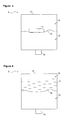
- Figure 3 - is the schematic view of the vibration transmitter used in an embodiment of the present invention.
- Figure 4 - is the schematic view of the vibration transmitter used in another embodiment of the present invention.
- Figure 5 - is the top schematic view of an embodiment of the present invention.
- the washing machine (1) comprises a drum (2) wherein the laundry is disposed, a tub (3) wherein the drum (2) moves, an air trap (4) wherein the air is compressed as the amount of water taken into the tub (3) increases, a vibration transmitter (5) which is disposed onto the tub (3) and wherein the air is compressed depending on the vibration of the tub (3), and a pressure sensor (6) which determines the amount of water inside the tub (3) by reading the pressure that is created by the air compressed in the air trap (4) and which determines the unbalanced load amount by reading the pressure that is created by the air compressed in the vibration transmitter (5).
- the washing machine (1) furthermore, comprises
- valve (8) being three-way and of its explained connections, in different washing steps, air transmission from the air trap pipe (9) and the vibration pipe (10) to the main pipe (7) and hence to the pressure sensor (6) can be controlled preferentially, and thus, during the performing of the unbalanced load detection and of the water level detection by means of a single pressure sensor (6), the two measurement processes are prevented from adversely affecting each other.
- the washing machine (1) comprises a counterweight (12) which is disposed onto the tub (3) in order to prevent the tub (3) from being displaced excessively, and the vibration transmitter (5) is disposed onto the said counterweight (12) ( Figure 1 ).
- the vibration transmitter (5) detects the vibration of the tub (3) with high accuracy, ease of assembly is provided.
- the washing machine (1) of the present invention applies a washing algorithm which preferably comprises water intake, washing, discharge and spin-drying steps.
- the valve (8) is a three-way and three-position valve.
- both the water level measurement and the unbalanced load measurement are provided to be performed with high accuracy.
- the valve (8) is kept in the position wherein it will close the vibration pipe (10) outlet, and will open the air trap pipe (9) outlet and the main pipe (7) inlet.
- the air flow is allowed only from the air trap (4) to the main pipe (7), and throughout the water intake and washing steps, the water level measurement is provided to be performed robustly.
- the valve (8) At the end of the washing step and before the discharge step, the valve (8) is kept in the position wherein it will open the vibration pipe (10) outlet and the air trap pipe (9) outlet, and will close the main pipe (7) inlet.
- the pressure in each three of the main pipe (7), the air trap pipe (9) and the vibration pipe (10) is equalized with the pressure inside the tub (3).
- the valve (8) In the discharge step, the valve (8) is kept in the position wherein it will close the vibration pipe (10) outlet, and will open the air trap pipe (9) outlet and the main pipe (7) inlet.
- the pressure inside the vibration transmitter (5) is prevented from decreasing during the discharge step, and the level of water inside the tub (3) is provided to be measured throughout the discharge step.
- the valve (8) is kept in the position wherein it will open the vibration pipe (10) outlet and the main pipe (7) inlet, and will close the air trap pipe (9) outlet.
- the unbalanced load detection is provided to be performed with high accuracy without being affected by the pressure change occurring as a result of the vibrations in the air trap (4).
- the valve (8) has three ways and two positions. Thus, cost advantage is provided.
- the valve (8) in the water intake, washing, discharge and spin-drying steps, the valve (8) is kept in the positions which are explained in the previous embodiment with three ways and three positions. At the end of the washing step and before the discharge step, the valve (8) is brought to the position wherein it will open the vibration pipe (10) outlet and the main pipe (7) inlet, and will close the air trap pipe (9) outlet.
- the valve (8) is brought to the position wherein it will open the vibration pipe (10) outlet and the main pipe (7) inlet, and will close the air trap pipe (9) outlet. Since the valve (8) has two positions, it is not possible for the valve (8) to close the main pipe (7) inlet and to open the air trap pipe (9) inlet for pressure equalization at the end of the washing step and before the discharge step. However, in this situation, since the volume at the vibration pipe (10) side will be greater than the volume at the main pipe (7) side, problems will be confronted during the air intake to the main pipe (7) and during the equalization of the pressure therein with the other portions.
- the washing machine (1) in order that pressure equalization is provided at the end of the washing step and before the discharge step, the washing machine (1) comprises a chamber (11) located on the main pipe (7).
- the pressure equalization is provided to be performed since the total volume of the main pipe (7) and the chamber (11) will be close to the volume at the vibration pipe (10) side when the valve (8) is brought to the position wherein it will open the vibration pipe (10) outlet and the main pipe (7) inlet, and will close the air trap pipe (9) outlet.
- the valve (8) is brought to the position wherein it will open the vibration pipe (10) outlet and the main pipe (7) inlet, and will close the air trap pipe (9) outlet in order that the pressure equalization can be provided at the end of the washing step and before the discharge step
- the valve (8) is provided to be brought to the position wherein it will close the vibration pipe (10) outlet, and will open the main pipe (7) inlet and the air trap pipe (9) outlet, and air intake to the main pipe (7) is provided.
- the pressure equalization is completed by bringing the valve (8) to the position wherein it will open the vibration pipe (10) outlet and the main pipe (7) inlet, and will close the air trap pipe (9) outlet again.
- the three-way valve (8) comprises a shutter each, which is disposed at the air trap pipe (9) outlet and at the vibration pipe (10) outlet, and a T connector which connects these shutters to the main pipe (7).
- the present embodiment is provided to be realized with low cost.
- the valve (8) before the washing step, the valve (8) is kept in the position wherein it will open the vibration pipe (10) outlet, the air trap pipe (9) outlet and the main pipe (7) inlet.
- the pressure inside the pressure sensor (6) is balanced with the pressure in all pipes (7, 9, 10).
- the valve (8) throughout at least a part of the water intake step, the valve (8) is kept in this position and thus, the value of the static pressure inside the pressure sensor (6) is provided to increase.
- the value of the static pressure inside the pressure sensor (6) is brought by being increased and the negative oscillations in the read pressure values are provided to be detected accurately.
- the vibration transmitter (5) compresses the air located in the vibration transmitter (5).
- the vibration transmitter (5) comprises
- the weight (17) moves together with the tub (3) and thus, makes a vibration movement on the flexible barrier (16) at the same frequency of the tub (3) vibration, which depends on the load in the drum (2).As a result of this movement, the air located in the second compartment (15) is compressed and moves towards the vibration pipe (10).
- the pressure change which is created by the air compressed as a result of the vibration of the weight (17) is measured by the pressure sensor (6).
- the amount of the tub (3) vibration at that time in other words, the unbalanced load amount is determined.
- the weight (17) is produced from a solid material, for example, from wood or metal ( Figure 3 ).
- the weight (17) is a fluid, for example, oil which fills the first compartment (14) ( Figure 4 ).
- the vibration transmitter (5) comprises
- the vibration pipe valve (22) is first brought to the position wherein it will open the first pipe (20) outlet and will close the second pipe (21) outlet, and the data of the vibration at the front side of the tub (3) is received from the first transmitter (18).
- the vibration pipe valve (22) is brought to the position wherein it will close the first pipe (20) outlet and will open the second pipe (21) outlet and thus, this time, the data of the vibration at the rear side of the tub (3) is received from the second transmitter (19). By considering the difference between these two data, it is decided that the unbalanced load is at the front or at the back.
- the data relating both to the unbalanced load and to the water level is provided to be measured with high accuracy by using a single pressure sensor (6).
Landscapes
- Engineering & Computer Science (AREA)
- Textile Engineering (AREA)
- Control Of Washing Machine And Dryer (AREA)
Description
- The present invention relates to a washing machine wherein the water level measurement is made reliable.
- In washing machines, the level of the water received in the machine is determined by measuring the pressure of the air compressed inside the air trap, which is connected to the tub, as the manometric height of the water, rising in the tub, increases, and by comparing this pressure with the reference pressure value of the tub when it is empty.
- On the other hand, in horizontal-axis washing machines, in order that the spin-drying step can be efficiently performed, the laundry is required to be distributed to the drum wall equally in every direction. In the situation that the laundry cannot be distributed equally, the vibration in the washing machine increases at high speeds in the spin-drying step and this causes the dynamic and structural system of the machine to be damaged. Therefore, in horizontal-axis washing machines, unbalanced load detection methods are present. By means of these methods, the amount of unbalanced load, situated inside the machine in the spin-drying step of the machine, is determined and depending on the determined value, various distribution algorithms are applied for the distribution of the laundry on the drum wall if required and/or the spin-drying process is stopped.
- In the state of the art, in order to minimize the usage of additional elements for unbalanced load detection, embodiments, aimed at achieving the same result by a single element instead of multiple elements used for water level detection and for unbalanced load detection, have been developed.
- A state of the art embodiment is explained in the German Patent Application No
DE19616635 . In this application, a system which measures the fluctuations, occurring due to the imbalance, with regard to the pressure data, is described. - In the state of the art European Patent Application No
EP0967318 , a system which, by the pressure difference, measures the oscillations, that is, the imbalance, occurring in the tub, is explained. In an embodiment explained in the said application, the tube coming from the air trap and the tube coming from the vibration sensor are joined together by a T element and are connected to the pressure sensor by a single tube. In another embodiment, the tube coming from the air trap and the tube coming from the vibration sensor are connected to the pressure sensor separately. In this embodiment, a valve, which enables the tube coming from the air trap to be cut off when desired, is situated on the tube coming from the air trap. - In another state of the art document, the European Patent Application No
EP0750065 , a method, which relates to the interpretation of the data, received by the pressure sensor from the air trap, to be used for unbalanced load detection, is explained DocumentDE-B3-10 2005 028 253 discloses a washing machine according to the preamble ofclaim 1. - However, in these state of the art embodiments, while the measurement of the water level and of the unbalanced load is desired to be performed by means of a single pressure sensor, it cannot be prevented that these measurements affect each other in different steps of the washing process and that the measurement efficiency decreases in at least one of the measurements.
- The aim of the present invention is the realization of a washing machine wherein the measurement of the water level and of the unbalanced load amount is performed with low cost and high accuracy.
- The washing machine realized in order to attain the aim of the present invention is explicated in the claims.
- The washing machine comprises a main pipe which provides air to be transmitted to the pressure sensor, a three-way valve which is mounted to the inlet of the main pipe and which controls the air input to the main pipe and the air output therefrom, an air trap pipe, the inlet of which is connected to the air trap and the outlet of which is connected to the valve, and which provides the connection between the air trap and the main pipe, and a vibration pipe, the inlet of which is connected to the vibration transmitter and the outlet of which is connected to the valve and thus, which provides the connection between the vibration transmitter and the main pipe.
- By means of the valve being three-way and of its placement, air transmission can be provided to the pressure sensor preferentially. Thus, by a single pressure sensor, also the pressure balancing between the pipes is possible for performing a robust detection while both the water level and the unbalanced load are detected.
- In the preferred embodiment of the present invention, the washing machine comprises a counterweight which is disposed onto the tub. In this embodiment, the vibration transmitter is disposed onto the counterweight. The washing machine applies a washing algorithm which preferably comprises water intake, washing, discharge and spin-drying steps.
- In the preferred embodiment of the present invention, a three-way and three-position valve is used. The valve is kept in the position which will allow air flow only from the air trap pipe to the main pipe throughout the water intake and washing steps. Thus, in the water intake and washing steps, the water level measurement is performed with high accuracy.
- At the end of the washing step, the valve is brought to the position wherein it will allow air flow between the vibration pipe and the air trap pipe and will close the inlet of the main pipe; and thus, pressure balancing between the pipes is provided.
- In the discharge step, the outlet of the vibration pipe is closed and thus, the air flow is allowed only between the air trap pipe and the main pipe, again. Thus, both the pressure inside the vibration transmitter is prevented from decreasing during the discharge step and the level of water inside the tub is provided to be determined accurately during the discharge step.
- Finally, since the unbalanced load detection becomes important in the spin-drying step, the valve is brought to the position wherein air will flow into the main pipe only through the vibration pipe, and the unbalanced load measurement is provided to be performed accurately.
- In another embodiment of the present invention, the valve has three ways and two positions. Thus, cost advantage is provided. In this embodiment, in the water intake, washing, discharge and spin-drying steps, the valve is kept in the positions which are explained in the previous embodiment. At the end of the washing step and before the discharge step, the valve is brought to the position wherein the vibration pipe outlet and the main pipe inlet will be open and the air trap pipe outlet will be closed.
- In a version of this embodiment, in order that pressure equalization is provided at the end of the washing step and before the discharge step, the main pipe comprises a chamber. Thus, since the volume at the main pipe side is greater than the volume at the vibration pipe side, air flow is provided into the vibration pipe and thus, pressure balancing is possible.
- In the preferred embodiment of the present invention, the vibration transmitter comprises a box. The box has a first compartment, and a second compartment which is filled with air inside and whereto the vibration pipe is connected. The vibration transmitter, furthermore, comprises a flexible barrier which separates the first compartment and the second compartment, and a weight which, by being located in the first compartment, applies pressure to the flexible barrier according to the vibration of the tub and compresses the air located in the second compartment.
- In different embodiments of the present invention, the weight is produced from a solid or liquid material.
- In an embodiment of the present invention, the vibration transmitter comprises a first transmitter which is disposed at the front side of the tub, a second transmitter which is disposed at the rear side of the tub, a vibration pipe valve which controls the air input and output from the first transmitter and the second transmitter to the vibration pipe, a first pipe which connects the first transmitter and the vibration pipe valve to each other, and a second pipe which connects the second transmitter and the vibration pipe valve to each other. Thus, as well as the determination of the unbalanced load amount, also the determination of the data that the unbalanced load is at the front or at the back is possible.
- The model embodiments relating to the washing machine realized in order to attain the aim of the present invention are illustrated in the attached figures, where:
-
Figure 1 - is the front schematic view of a washing machine. -
Figure 2 - is the front schematic view of another embodiment of the present invention. -
Figure 3 - is the schematic view of the vibration transmitter used in an embodiment of the present invention. -
Figure 4 - is the schematic view of the vibration transmitter used in another embodiment of the present invention. -
Figure 5 - is the top schematic view of an embodiment of the present invention. - The elements illustrated in the figures are numbered as follows:
- 1. Washing machine
- 2. Drum
- 3. Tub
- 4. Air trap
- 5. Vibration transmitter
- 6. Pressure sensor
- 7. Main pipe
- 8. Valve
- 9. Air trap pipe
- 10. Vibration pipe
- 11. Chamber
- 12. Counterweight
- 13. Box
- 14. First compartment
- 15. Second compartment
- 16. Flexible barrier
- 17. Weight
- 18. First transmitter
- 19. Second transmitter
- 20. First pipe
- 21. Second pipe
- 22. Vibration pipe valve
- The washing machine (1) comprises a drum (2) wherein the laundry is disposed, a tub (3) wherein the drum (2) moves, an air trap (4) wherein the air is compressed as the amount of water taken into the tub (3) increases, a vibration transmitter (5) which is disposed onto the tub (3) and wherein the air is compressed depending on the vibration of the tub (3), and a pressure sensor (6) which determines the amount of water inside the tub (3) by reading the pressure that is created by the air compressed in the air trap (4) and which determines the unbalanced load amount by reading the pressure that is created by the air compressed in the vibration transmitter (5).
- The washing machine (1), furthermore, comprises
- a main pipe (7) which provides air to be transmitted to the pressure sensor (6),
- a three-way valve (8) which is mounted to the inlet of the main pipe (7) and which controls the air input to the main pipe (7) and the air output therefrom,
- an air trap pipe (9), the inlet of which is connected to the air trap (4) and the outlet of which is connected to the valve (8), and which provides the connection between the air trap (4) and the main pipe (7),
- a vibration pipe (10), the inlet of which is connected to the vibration transmitter (5) and the outlet of which is connected to the valve (8), and which provides the connection between the vibration transmitter (5) and the main pipe (7)
- (
Figure 1 ). - By means of the valve (8) being three-way and of its explained connections, in different washing steps, air transmission from the air trap pipe (9) and the vibration pipe (10) to the main pipe (7) and hence to the pressure sensor (6) can be controlled preferentially, and thus, during the performing of the unbalanced load detection and of the water level detection by means of a single pressure sensor (6), the two measurement processes are prevented from adversely affecting each other.
- In the preferred embodiment of the present invention, the washing machine (1) comprises a counterweight (12) which is disposed onto the tub (3) in order to prevent the tub (3) from being displaced excessively, and the vibration transmitter (5) is disposed onto the said counterweight (12) (
Figure 1 ). Thus, as well as the vibration transmitter (5) detects the vibration of the tub (3) with high accuracy, ease of assembly is provided. - The washing machine (1) of the present invention applies a washing algorithm which preferably comprises water intake, washing, discharge and spin-drying steps.
- In the preferred embodiment of the present invention, the valve (8) is a three-way and three-position valve. Thus, both the water level measurement and the unbalanced load measurement are provided to be performed with high accuracy.
- In this embodiment, throughout the water intake and washing steps, the valve (8) is kept in the position wherein it will close the vibration pipe (10) outlet, and will open the air trap pipe (9) outlet and the main pipe (7) inlet. Thus, the air flow is allowed only from the air trap (4) to the main pipe (7), and throughout the water intake and washing steps, the water level measurement is provided to be performed robustly.
- At the end of the washing step and before the discharge step, the valve (8) is kept in the position wherein it will open the vibration pipe (10) outlet and the air trap pipe (9) outlet, and will close the main pipe (7) inlet. Thus, the pressure in each three of the main pipe (7), the air trap pipe (9) and the vibration pipe (10) is equalized with the pressure inside the tub (3). In the discharge step, the valve (8) is kept in the position wherein it will close the vibration pipe (10) outlet, and will open the air trap pipe (9) outlet and the main pipe (7) inlet. Thus, the pressure inside the vibration transmitter (5) is prevented from decreasing during the discharge step, and the level of water inside the tub (3) is provided to be measured throughout the discharge step.
- During the spin-drying step, the valve (8) is kept in the position wherein it will open the vibration pipe (10) outlet and the main pipe (7) inlet, and will close the air trap pipe (9) outlet. Thus, during the spin-drying step, the unbalanced load detection is provided to be performed with high accuracy without being affected by the pressure change occurring as a result of the vibrations in the air trap (4).
- The position of the valve (8) in different washing steps in this embodiment is summarized in the following table.
-
Table 1 Vibration pipe (10) outlet Main pipe (7) inlet Air trap pipe (9) outlet Water intake and washing steps Closed Open Open At the end of the washing step, before the discharge step Open Closed Open Discharge step Closed Open Open Spin-drying step Open Open Closed - In another embodiment of the present invention, the valve (8) has three ways and two positions. Thus, cost advantage is provided.
- In this embodiment, in the water intake, washing, discharge and spin-drying steps, the valve (8) is kept in the positions which are explained in the previous embodiment with three ways and three positions. At the end of the washing step and before the discharge step, the valve (8) is brought to the position wherein it will open the vibration pipe (10) outlet and the main pipe (7) inlet, and will close the air trap pipe (9) outlet.
- The position of the valve (8) in different washing steps in this embodiment is summarized in the following table.
-
Table 2 Vibration pipe (10) outlet Main pipe (7) inlet Air trap pipe (9) outlet Water intake and washing steps Closed Open Open At the end of the washing step, before the Open Open Closed discharge step Discharge step Closed Open Open Spin-drying step Open Open Closed - As stated above, in this embodiment, at the end of the washing step and before the discharge step, the valve (8) is brought to the position wherein it will open the vibration pipe (10) outlet and the main pipe (7) inlet, and will close the air trap pipe (9) outlet. Since the valve (8) has two positions, it is not possible for the valve (8) to close the main pipe (7) inlet and to open the air trap pipe (9) inlet for pressure equalization at the end of the washing step and before the discharge step. However, in this situation, since the volume at the vibration pipe (10) side will be greater than the volume at the main pipe (7) side, problems will be confronted during the air intake to the main pipe (7) and during the equalization of the pressure therein with the other portions.
- In a version of this embodiment, in order that pressure equalization is provided at the end of the washing step and before the discharge step, the washing machine (1) comprises a chamber (11) located on the main pipe (7). Thus, at the end of the washing step and before the discharge step, the pressure equalization is provided to be performed since the total volume of the main pipe (7) and the chamber (11) will be close to the volume at the vibration pipe (10) side when the valve (8) is brought to the position wherein it will open the vibration pipe (10) outlet and the main pipe (7) inlet, and will close the air trap pipe (9) outlet.
- In another version of this embodiment, after the valve (8) is brought to the position wherein it will open the vibration pipe (10) outlet and the main pipe (7) inlet, and will close the air trap pipe (9) outlet in order that the pressure equalization can be provided at the end of the washing step and before the discharge step, the valve (8) is provided to be brought to the position wherein it will close the vibration pipe (10) outlet, and will open the main pipe (7) inlet and the air trap pipe (9) outlet, and air intake to the main pipe (7) is provided. Then, the pressure equalization is completed by bringing the valve (8) to the position wherein it will open the vibration pipe (10) outlet and the main pipe (7) inlet, and will close the air trap pipe (9) outlet again.
- In the preferred version of this embodiment, the three-way valve (8) comprises a shutter each, which is disposed at the air trap pipe (9) outlet and at the vibration pipe (10) outlet, and a T connector which connects these shutters to the main pipe (7). Thus, the present embodiment is provided to be realized with low cost.
- In an embodiment of the present invention, before the washing step, the valve (8) is kept in the position wherein it will open the vibration pipe (10) outlet, the air trap pipe (9) outlet and the main pipe (7) inlet. Thus, the pressure inside the pressure sensor (6) is balanced with the pressure in all pipes (7, 9, 10). In this embodiment, throughout at least a part of the water intake step, the valve (8) is kept in this position and thus, the value of the static pressure inside the pressure sensor (6) is provided to increase. Thus, the value of the static pressure inside the pressure sensor (6) is brought by being increased and the negative oscillations in the read pressure values are provided to be detected accurately.
- Depending on the displacement occurring in the tub (3), the vibration transmitter (5) compresses the air located in the vibration transmitter (5). In the preferred embodiment of the present invention, the vibration transmitter (5) comprises
- a box (13) having a first compartment (14), and a second compartment (15) which is filled with air inside and whereto the vibration pipe (10) is connected,
- a flexible barrier (16) which separates the first compartment (14) and the second compartment (15) from each other,
- a weight (17) which is located in the first compartment (14) and which, depending on the vibration of the tub (3), applies pressure to the flexible barrier (16) and which compresses the air located in the second compartment (15)
- (
Figure 3 and Figure 4 ). - The weight (17) moves together with the tub (3) and thus, makes a vibration movement on the flexible barrier (16) at the same frequency of the tub (3) vibration, which depends on the load in the drum (2).As a result of this movement, the air located in the second compartment (15) is compressed and moves towards the vibration pipe (10). Thus, in the situation wherein the valve (8) allows air flow from the vibration pipe (10) to the main pipe (7) and hence to the pressure sensor (6), the pressure change, which is created by the air compressed as a result of the vibration of the weight (17), is measured by the pressure sensor (6). Thus, the amount of the tub (3) vibration at that time, in other words, the unbalanced load amount is determined.
- In an embodiment of the present invention, the weight (17) is produced from a solid material, for example, from wood or metal (
Figure 3 ). In another embodiment of the present invention, the weight (17) is a fluid, for example, oil which fills the first compartment (14) (Figure 4 ). - In an embodiment of the present invention, the vibration transmitter (5) comprises
- a first transmitter (18) which is disposed at the front side in order to detect the vibration at the front side of the tub (3),
- a second transmitter (19) which is disposed at the rear side in order to detect the vibration at the rear side of the tub (3),
- a vibration pipe valve (22) which controls the air flow from the first transmitter (18) and the second transmitter (19) to the vibration pipe (10),
- a first pipe (20) which provides the connection between the first transmitter (18) and the vibration pipe valve (22), and
- a second pipe (21) which provides the connection between the second transmitter (19) and the vibration pipe valve (22)
- (
Figure 5 ). - Thus, as well as the determination of the unbalanced load amount, also the determination of the data that the load is at the front or at the back is possible. In this embodiment, during the spin-drying step, while the valve (8) is in the position wherein it will open the vibration pipe (10) outlet and the main pipe (7) inlet, and will close the air trap pipe (9) outlet, the vibration pipe valve (22) is first brought to the position wherein it will open the first pipe (20) outlet and will close the second pipe (21) outlet, and the data of the vibration at the front side of the tub (3) is received from the first transmitter (18). Then, the vibration pipe valve (22) is brought to the position wherein it will close the first pipe (20) outlet and will open the second pipe (21) outlet and thus, this time, the data of the vibration at the rear side of the tub (3) is received from the second transmitter (19). By considering the difference between these two data, it is decided that the unbalanced load is at the front or at the back.
- In the washing machine (1) of the present invention, the data relating both to the unbalanced load and to the water level is provided to be measured with high accuracy by using a single pressure sensor (6).
- It is to be understood that the present invention is not limited to the embodiments disclosed above and a person skilled in the art can easily introduce different embodiments. These should be considered within the scope of the protection postulated by the claims of the present invention.
Claims (15)
- A washing machine (1) comprising a drum (2) wherein the laundry is disposed, a tub (3) wherein the drum (2) moves, an air trap (4) wherein the air is compressed as the amount of water taken into the tub (3) increases, a vibration transmitter (5) which is disposed onto the tub (3) and wherein the air is compressed depending on the vibration of the tub (3), and a pressure sensor (6) which determines the amount of water inside the tub (3) by reading the pressure that is created by the air compressed in the air trap (4) and which determines the unbalanced load amount by reading the pressure that is created by the air compressed in the vibration transmitter (5), characterized by- a main pipe (7) which provides air to be transmitted to the pressure sensor (6),- a three-way valve (8) which is mounted to the inlet of the main pipe (7) and which controls the air input to the main pipe (7) and the air output therefrom,- an air trap pipe (9), the inlet of which is connected to the air trap (4) and the outlet of which is connected to the valve (8), and which provides the connection between the air trap (4) and the main pipe (7),- a vibration pipe (10), the inlet of which is connected to the vibration transmitter (5) and the outlet of which is connected to the valve (8), and which provides the connection between the vibration transmitter (5) and the main pipe (7).
- A washing machine (1) as in Claim 1, characterized by a counterweight (12) which is disposed onto the tub (3) in order to prevent the tub (3) from being displaced excessively, and by the vibration transmitter (5) which is disposed onto the counterweight (12).
- A washing machine (1) as in Claim 1 or 2, wherein a washing algorithm, comprising water intake, washing, discharge and spin-drying steps, is applied.
- A washing machine (1) as in any one of the above Claims, characterized by the three-way and three-position valve (8).
- A washing machine (1) as in Claim 4, characterized by the valve (8) which, throughout the water intake and washing steps, is kept in the position wherein it will close the vibration pipe (10) outlet, and will open the air trap pipe (9) outlet and the main pipe (7) inlet.
- A washing machine (1) as in Claim 4 or 5, characterized by the valve (8) which, at the end of the washing step and before the discharge step, is brought to the position wherein it will open the vibration pipe (10) outlet and the air trap pipe (9) outlet, and will close the main pipe (7) inlet.
- A washing machine (1) as in any one of the Claims 4 to 6, characterized by the valve (8) which, in the discharge step, is kept in the position wherein it will close the vibration pipe (10) outlet, and will open the air trap pipe (9) outlet and the main pipe (7) inlet.
- A washing machine (1) as in any one of the Claims 4 to 7, characterized by the valve (8) which, during the spin-drying step, is kept in the position wherein it will open the vibration pipe (10) outlet and the main pipe (7) inlet, and will close the air trap pipe (9) outlet.
- A washing machine (1) as in any one of the Claims 1 to 3, characterized by the three-way and two-position valve (8).
- A washing machine (1) as in Claim 9, characterized by the valve (8) which, throughout the water intake and washing steps, is kept in the position wherein it will close the vibration pipe (10) outlet, and will open the air trap pipe (9) outlet and the main pipe (7) inlet.
- A washing machine (1) as in Claim 9 or 10, characterized by the valve (8) which, at the end of the washing step and before the discharge step, is brought to the position wherein it will open the vibration pipe (10) outlet and the main pipe (7) inlet, and will close the air trap pipe (9) outlet.
- A washing machine (1) as in any one of the Claims 9 to 11, characterized by the valve (8) which, in the discharge step, is kept in the position wherein it will close the vibration pipe (10) outlet, and will open the air trap pipe (9) outlet and the main pipe (7) inlet.
- A washing machine (1) as in any one of the Claims 9 to 12, characterized by the valve (8) which, during the spin-drying step, is kept in the position wherein it will open the vibration pipe (10) outlet and the main pipe (7) inlet, and will close the air trap pipe (9) outlet.
- A washing machine as in any one of the above Claims, characterized by the vibration transmitter (5) that comprises- a box (13) having a first compartment (14), and a second compartment (15) which is filled with air inside and whereto the vibration pipe (10) is connected,- a flexible barrier (16) which separates the first compartment (14) and the second compartment (15) from each other,- a weight (17) which is located in the first compartment (14) and which, depending on the vibration of the tub (3), applies pressure to the flexible barrier (16) and which compresses the air located in the second compartment (15).
- A washing machine (1) as in any one of the above Claims, characterized by the vibration transmitter (5) that comprises- a first transmitter (18) which is disposed at the front side in order to detect the vibration at the front side of the tub (3),- a second transmitter (19) which is disposed at the rear side in order to detect the vibration at the rear side of the tub (3),- a vibration pipe valve (22) which controls the air flow from the first transmitter (18) and the second transmitter (19) to the vibration pipe (10),- a first pipe (20) which provides the connection between the first transmitter (18) and the vibration pipe valve (22), and- a second pipe (21) which provides the connection between the second transmitter (19) and the vibration pipe valve (22).
Applications Claiming Priority (2)
| Application Number | Priority Date | Filing Date | Title |
|---|---|---|---|
| TR200810080 | 2008-12-31 | ||
| PCT/EP2009/067146 WO2010076186A1 (en) | 2008-12-31 | 2009-12-15 | A washing machine comprising an air trap |
Publications (2)
| Publication Number | Publication Date |
|---|---|
| EP2384377A1 EP2384377A1 (en) | 2011-11-09 |
| EP2384377B1 true EP2384377B1 (en) | 2012-11-28 |
Family
ID=41820431
Family Applications (1)
| Application Number | Title | Priority Date | Filing Date |
|---|---|---|---|
| EP09771376A Not-in-force EP2384377B1 (en) | 2008-12-31 | 2009-12-15 | A washing machine comprising an air trap |
Country Status (2)
| Country | Link |
|---|---|
| EP (1) | EP2384377B1 (en) |
| WO (1) | WO2010076186A1 (en) |
Family Cites Families (5)
| Publication number | Priority date | Publication date | Assignee | Title |
|---|---|---|---|---|
| GB2073257B (en) * | 1980-02-19 | 1983-07-27 | Kenwood Mfg Co Ltd | Washing machines and spindriers |
| JPH0994380A (en) * | 1995-09-29 | 1997-04-08 | Matsushita Electric Ind Co Ltd | Washing machine |
| DE19928383A1 (en) * | 1998-06-27 | 1999-12-30 | Miele & Cie | Washing machine with imbalance measuring system |
| DE10110854C5 (en) * | 2000-04-07 | 2010-03-04 | Miele & Cie. Kg | Device for determining the imbalance in a drum washing machine |
| DE102005028253B3 (en) * | 2005-06-17 | 2006-11-02 | Emz-Hanauer Gmbh & Co. Kgaa | Device and method to detect movement in a rotating component of a household appliance caused by imbalance has movable mass spring and damper with mass moving outwards above a given imbalance frequency |
-
2009
- 2009-12-15 EP EP09771376A patent/EP2384377B1/en not_active Not-in-force
- 2009-12-15 WO PCT/EP2009/067146 patent/WO2010076186A1/en not_active Ceased
Also Published As
| Publication number | Publication date |
|---|---|
| WO2010076186A1 (en) | 2010-07-08 |
| EP2384377A1 (en) | 2011-11-09 |
Similar Documents
| Publication | Publication Date | Title |
|---|---|---|
| CN109667109B (en) | Inner cylinder structure, washing machine and eccentric balancing method of washing machine | |
| CN104790179B (en) | Washing machine and its carry out shock detection, load weigh, the method for cloth quality detection | |
| US20120204627A1 (en) | Method for Establishing Cavitation in Hydrostatic Devices and Control Device | |
| US10328192B2 (en) | Relative pump calibration for ultrafiltration control in a dialysis apparatus | |
| US5720064A (en) | Washing machine water level detecting method using weight sensor | |
| EP2094893B1 (en) | Method for determining weight of the load in a washer dryer using the natural frequency response of the loaded drum | |
| CN108239850A (en) | A kind of water level of washing machine control method and washing machine | |
| EP2413106A1 (en) | Method for measuring the water flow rate in a washing machine | |
| WO2010076186A1 (en) | A washing machine comprising an air trap | |
| CN112011957B (en) | Washing machine, eccentricity detection method and device thereof, and storage medium | |
| CN113614304A (en) | Balancing system for washing machine | |
| KR20090114602A (en) | Drum Washing Machine and Control Method | |
| WO2010076148A1 (en) | A washing machine comprising an air trap | |
| CN108691145B (en) | Washing machine unbalance loading indicating device, washing machine and unbalance loading detection method | |
| KR102348371B1 (en) | Control method for laundry treating apparatus | |
| CN112095287B (en) | Washing machine dehydration control method and washing machine | |
| CN210420557U (en) | Washing machine with automatic clothes drying degree detection function | |
| CN115928371A (en) | Control method of washing machine and washing machine | |
| CN211395029U (en) | A drum washing machine | |
| US9322123B2 (en) | Level measuring device for a wall mounted drum type washing machine and method thereof | |
| EP1614794A2 (en) | Pressure and vibration sensitive apparatus | |
| JPH0875508A (en) | Simple flow meter with pump performance deterioration detection | |
| WO2008052980A1 (en) | A washing machine | |
| CN115807312B (en) | Washing machine and detection method thereof | |
| JPH09168691A (en) | Washing machine water level measuring device |
Legal Events
| Date | Code | Title | Description |
|---|---|---|---|
| PUAI | Public reference made under article 153(3) epc to a published international application that has entered the european phase |
Free format text: ORIGINAL CODE: 0009012 |
|
| 17P | Request for examination filed |
Effective date: 20110623 |
|
| AK | Designated contracting states |
Kind code of ref document: A1 Designated state(s): AT BE BG CH CY CZ DE DK EE ES FI FR GB GR HR HU IE IS IT LI LT LU LV MC MK MT NL NO PL PT RO SE SI SK SM TR |
|
| DAX | Request for extension of the european patent (deleted) | ||
| GRAP | Despatch of communication of intention to grant a patent |
Free format text: ORIGINAL CODE: EPIDOSNIGR1 |
|
| GRAS | Grant fee paid |
Free format text: ORIGINAL CODE: EPIDOSNIGR3 |
|
| GRAA | (expected) grant |
Free format text: ORIGINAL CODE: 0009210 |
|
| AK | Designated contracting states |
Kind code of ref document: B1 Designated state(s): AT BE BG CH CY CZ DE DK EE ES FI FR GB GR HR HU IE IS IT LI LT LU LV MC MK MT NL NO PL PT RO SE SI SK SM TR |
|
| REG | Reference to a national code |
Ref country code: GB Ref legal event code: FG4D |
|
| REG | Reference to a national code |
Ref country code: CH Ref legal event code: EP |
|
| REG | Reference to a national code |
Ref country code: AT Ref legal event code: REF Ref document number: 586252 Country of ref document: AT Kind code of ref document: T Effective date: 20121215 |
|
| REG | Reference to a national code |
Ref country code: IE Ref legal event code: FG4D |
|
| REG | Reference to a national code |
Ref country code: DE Ref legal event code: R096 Ref document number: 602009011578 Country of ref document: DE Effective date: 20130124 |
|
| REG | Reference to a national code |
Ref country code: AT Ref legal event code: MK05 Ref document number: 586252 Country of ref document: AT Kind code of ref document: T Effective date: 20121128 |
|
| REG | Reference to a national code |
Ref country code: NL Ref legal event code: VDEP Effective date: 20121128 |
|
| REG | Reference to a national code |
Ref country code: LT Ref legal event code: MG4D |
|
| PG25 | Lapsed in a contracting state [announced via postgrant information from national office to epo] |
Ref country code: SE Free format text: LAPSE BECAUSE OF FAILURE TO SUBMIT A TRANSLATION OF THE DESCRIPTION OR TO PAY THE FEE WITHIN THE PRESCRIBED TIME-LIMIT Effective date: 20121128 Ref country code: ES Free format text: LAPSE BECAUSE OF FAILURE TO SUBMIT A TRANSLATION OF THE DESCRIPTION OR TO PAY THE FEE WITHIN THE PRESCRIBED TIME-LIMIT Effective date: 20130311 Ref country code: NO Free format text: LAPSE BECAUSE OF FAILURE TO SUBMIT A TRANSLATION OF THE DESCRIPTION OR TO PAY THE FEE WITHIN THE PRESCRIBED TIME-LIMIT Effective date: 20130228 Ref country code: LT Free format text: LAPSE BECAUSE OF FAILURE TO SUBMIT A TRANSLATION OF THE DESCRIPTION OR TO PAY THE FEE WITHIN THE PRESCRIBED TIME-LIMIT Effective date: 20121128 Ref country code: HR Free format text: LAPSE BECAUSE OF FAILURE TO SUBMIT A TRANSLATION OF THE DESCRIPTION OR TO PAY THE FEE WITHIN THE PRESCRIBED TIME-LIMIT Effective date: 20121128 Ref country code: FI Free format text: LAPSE BECAUSE OF FAILURE TO SUBMIT A TRANSLATION OF THE DESCRIPTION OR TO PAY THE FEE WITHIN THE PRESCRIBED TIME-LIMIT Effective date: 20121128 |
|
| PG25 | Lapsed in a contracting state [announced via postgrant information from national office to epo] |
Ref country code: PT Free format text: LAPSE BECAUSE OF FAILURE TO SUBMIT A TRANSLATION OF THE DESCRIPTION OR TO PAY THE FEE WITHIN THE PRESCRIBED TIME-LIMIT Effective date: 20130328 Ref country code: BE Free format text: LAPSE BECAUSE OF FAILURE TO SUBMIT A TRANSLATION OF THE DESCRIPTION OR TO PAY THE FEE WITHIN THE PRESCRIBED TIME-LIMIT Effective date: 20121128 Ref country code: SI Free format text: LAPSE BECAUSE OF FAILURE TO SUBMIT A TRANSLATION OF THE DESCRIPTION OR TO PAY THE FEE WITHIN THE PRESCRIBED TIME-LIMIT Effective date: 20121128 Ref country code: GR Free format text: LAPSE BECAUSE OF FAILURE TO SUBMIT A TRANSLATION OF THE DESCRIPTION OR TO PAY THE FEE WITHIN THE PRESCRIBED TIME-LIMIT Effective date: 20130301 Ref country code: LV Free format text: LAPSE BECAUSE OF FAILURE TO SUBMIT A TRANSLATION OF THE DESCRIPTION OR TO PAY THE FEE WITHIN THE PRESCRIBED TIME-LIMIT Effective date: 20121128 Ref country code: PL Free format text: LAPSE BECAUSE OF FAILURE TO SUBMIT A TRANSLATION OF THE DESCRIPTION OR TO PAY THE FEE WITHIN THE PRESCRIBED TIME-LIMIT Effective date: 20121128 |
|
| PG25 | Lapsed in a contracting state [announced via postgrant information from national office to epo] |
Ref country code: AT Free format text: LAPSE BECAUSE OF FAILURE TO SUBMIT A TRANSLATION OF THE DESCRIPTION OR TO PAY THE FEE WITHIN THE PRESCRIBED TIME-LIMIT Effective date: 20121128 |
|
| PG25 | Lapsed in a contracting state [announced via postgrant information from national office to epo] |
Ref country code: CZ Free format text: LAPSE BECAUSE OF FAILURE TO SUBMIT A TRANSLATION OF THE DESCRIPTION OR TO PAY THE FEE WITHIN THE PRESCRIBED TIME-LIMIT Effective date: 20121128 Ref country code: EE Free format text: LAPSE BECAUSE OF FAILURE TO SUBMIT A TRANSLATION OF THE DESCRIPTION OR TO PAY THE FEE WITHIN THE PRESCRIBED TIME-LIMIT Effective date: 20121128 Ref country code: SK Free format text: LAPSE BECAUSE OF FAILURE TO SUBMIT A TRANSLATION OF THE DESCRIPTION OR TO PAY THE FEE WITHIN THE PRESCRIBED TIME-LIMIT Effective date: 20121128 Ref country code: BG Free format text: LAPSE BECAUSE OF FAILURE TO SUBMIT A TRANSLATION OF THE DESCRIPTION OR TO PAY THE FEE WITHIN THE PRESCRIBED TIME-LIMIT Effective date: 20130228 Ref country code: DK Free format text: LAPSE BECAUSE OF FAILURE TO SUBMIT A TRANSLATION OF THE DESCRIPTION OR TO PAY THE FEE WITHIN THE PRESCRIBED TIME-LIMIT Effective date: 20121128 Ref country code: MC Free format text: LAPSE BECAUSE OF NON-PAYMENT OF DUE FEES Effective date: 20121231 |
|
| PG25 | Lapsed in a contracting state [announced via postgrant information from national office to epo] |
Ref country code: RO Free format text: LAPSE BECAUSE OF FAILURE TO SUBMIT A TRANSLATION OF THE DESCRIPTION OR TO PAY THE FEE WITHIN THE PRESCRIBED TIME-LIMIT Effective date: 20121128 Ref country code: IT Free format text: LAPSE BECAUSE OF FAILURE TO SUBMIT A TRANSLATION OF THE DESCRIPTION OR TO PAY THE FEE WITHIN THE PRESCRIBED TIME-LIMIT Effective date: 20121128 Ref country code: NL Free format text: LAPSE BECAUSE OF FAILURE TO SUBMIT A TRANSLATION OF THE DESCRIPTION OR TO PAY THE FEE WITHIN THE PRESCRIBED TIME-LIMIT Effective date: 20121128 |
|
| REG | Reference to a national code |
Ref country code: IE Ref legal event code: MM4A |
|
| PLBE | No opposition filed within time limit |
Free format text: ORIGINAL CODE: 0009261 |
|
| STAA | Information on the status of an ep patent application or granted ep patent |
Free format text: STATUS: NO OPPOSITION FILED WITHIN TIME LIMIT |
|
| PG25 | Lapsed in a contracting state [announced via postgrant information from national office to epo] |
Ref country code: IE Free format text: LAPSE BECAUSE OF NON-PAYMENT OF DUE FEES Effective date: 20121215 |
|
| 26N | No opposition filed |
Effective date: 20130829 |
|
| PG25 | Lapsed in a contracting state [announced via postgrant information from national office to epo] |
Ref country code: CY Free format text: LAPSE BECAUSE OF FAILURE TO SUBMIT A TRANSLATION OF THE DESCRIPTION OR TO PAY THE FEE WITHIN THE PRESCRIBED TIME-LIMIT Effective date: 20121128 Ref country code: MT Free format text: LAPSE BECAUSE OF FAILURE TO SUBMIT A TRANSLATION OF THE DESCRIPTION OR TO PAY THE FEE WITHIN THE PRESCRIBED TIME-LIMIT Effective date: 20121128 |
|
| REG | Reference to a national code |
Ref country code: FR Ref legal event code: ST Effective date: 20131107 |
|
| REG | Reference to a national code |
Ref country code: DE Ref legal event code: R097 Ref document number: 602009011578 Country of ref document: DE Effective date: 20130829 |
|
| PG25 | Lapsed in a contracting state [announced via postgrant information from national office to epo] |
Ref country code: FR Free format text: LAPSE BECAUSE OF NON-PAYMENT OF DUE FEES Effective date: 20130128 |
|
| PG25 | Lapsed in a contracting state [announced via postgrant information from national office to epo] |
Ref country code: SM Free format text: LAPSE BECAUSE OF FAILURE TO SUBMIT A TRANSLATION OF THE DESCRIPTION OR TO PAY THE FEE WITHIN THE PRESCRIBED TIME-LIMIT Effective date: 20121128 Ref country code: LU Free format text: LAPSE BECAUSE OF NON-PAYMENT OF DUE FEES Effective date: 20121215 |
|
| PG25 | Lapsed in a contracting state [announced via postgrant information from national office to epo] |
Ref country code: HU Free format text: LAPSE BECAUSE OF FAILURE TO SUBMIT A TRANSLATION OF THE DESCRIPTION OR TO PAY THE FEE WITHIN THE PRESCRIBED TIME-LIMIT Effective date: 20091215 |
|
| REG | Reference to a national code |
Ref country code: CH Ref legal event code: PL |
|
| GBPC | Gb: european patent ceased through non-payment of renewal fee |
Effective date: 20131215 |
|
| PG25 | Lapsed in a contracting state [announced via postgrant information from national office to epo] |
Ref country code: CH Free format text: LAPSE BECAUSE OF NON-PAYMENT OF DUE FEES Effective date: 20131231 Ref country code: LI Free format text: LAPSE BECAUSE OF NON-PAYMENT OF DUE FEES Effective date: 20131231 |
|
| PG25 | Lapsed in a contracting state [announced via postgrant information from national office to epo] |
Ref country code: GB Free format text: LAPSE BECAUSE OF NON-PAYMENT OF DUE FEES Effective date: 20131215 |
|
| PG25 | Lapsed in a contracting state [announced via postgrant information from national office to epo] |
Ref country code: MK Free format text: LAPSE BECAUSE OF FAILURE TO SUBMIT A TRANSLATION OF THE DESCRIPTION OR TO PAY THE FEE WITHIN THE PRESCRIBED TIME-LIMIT Effective date: 20121128 |
|
| PG25 | Lapsed in a contracting state [announced via postgrant information from national office to epo] |
Ref country code: IS Free format text: LAPSE BECAUSE OF FAILURE TO SUBMIT A TRANSLATION OF THE DESCRIPTION OR TO PAY THE FEE WITHIN THE PRESCRIBED TIME-LIMIT Effective date: 20121128 |
|
| PGFP | Annual fee paid to national office [announced via postgrant information from national office to epo] |
Ref country code: DE Payment date: 20161213 Year of fee payment: 8 |
|
| PGFP | Annual fee paid to national office [announced via postgrant information from national office to epo] |
Ref country code: TR Payment date: 20161117 Year of fee payment: 8 |
|
| REG | Reference to a national code |
Ref country code: DE Ref legal event code: R119 Ref document number: 602009011578 Country of ref document: DE |
|
| PG25 | Lapsed in a contracting state [announced via postgrant information from national office to epo] |
Ref country code: DE Free format text: LAPSE BECAUSE OF NON-PAYMENT OF DUE FEES Effective date: 20180703 |
|
| PG25 | Lapsed in a contracting state [announced via postgrant information from national office to epo] |
Ref country code: TR Free format text: LAPSE BECAUSE OF NON-PAYMENT OF DUE FEES Effective date: 20171215 |