EP2384109A1 - Heat exchanger device and heating element holder using same - Google Patents
Heat exchanger device and heating element holder using same Download PDFInfo
- Publication number
- EP2384109A1 EP2384109A1 EP10738358A EP10738358A EP2384109A1 EP 2384109 A1 EP2384109 A1 EP 2384109A1 EP 10738358 A EP10738358 A EP 10738358A EP 10738358 A EP10738358 A EP 10738358A EP 2384109 A1 EP2384109 A1 EP 2384109A1
- Authority
- EP
- European Patent Office
- Prior art keywords
- heat exchanger
- air
- environment
- exchanger device
- port
- Prior art date
- Legal status (The legal status is an assumption and is not a legal conclusion. Google has not performed a legal analysis and makes no representation as to the accuracy of the status listed.)
- Withdrawn
Links
Images







Classifications
-
- F—MECHANICAL ENGINEERING; LIGHTING; HEATING; WEAPONS; BLASTING
- F24—HEATING; RANGES; VENTILATING
- F24F—AIR-CONDITIONING; AIR-HUMIDIFICATION; VENTILATION; USE OF AIR CURRENTS FOR SCREENING
- F24F12/00—Use of energy recovery systems in air conditioning, ventilation or screening
- F24F12/001—Use of energy recovery systems in air conditioning, ventilation or screening with heat-exchange between supplied and exhausted air
- F24F12/006—Use of energy recovery systems in air conditioning, ventilation or screening with heat-exchange between supplied and exhausted air using an air-to-air heat exchanger
-
- H—ELECTRICITY
- H05—ELECTRIC TECHNIQUES NOT OTHERWISE PROVIDED FOR
- H05K—PRINTED CIRCUITS; CASINGS OR CONSTRUCTIONAL DETAILS OF ELECTRIC APPARATUS; MANUFACTURE OF ASSEMBLAGES OF ELECTRICAL COMPONENTS
- H05K7/00—Constructional details common to different types of electric apparatus
- H05K7/20—Modifications to facilitate cooling, ventilating, or heating
- H05K7/20536—Modifications to facilitate cooling, ventilating, or heating for racks or cabinets of standardised dimensions, e.g. electronic racks for aircraft or telecommunication equipment
- H05K7/206—Air circulating in closed loop within cabinets wherein heat is removed through air-to-air heat-exchanger
-
- Y—GENERAL TAGGING OF NEW TECHNOLOGICAL DEVELOPMENTS; GENERAL TAGGING OF CROSS-SECTIONAL TECHNOLOGIES SPANNING OVER SEVERAL SECTIONS OF THE IPC; TECHNICAL SUBJECTS COVERED BY FORMER USPC CROSS-REFERENCE ART COLLECTIONS [XRACs] AND DIGESTS
- Y02—TECHNOLOGIES OR APPLICATIONS FOR MITIGATION OR ADAPTATION AGAINST CLIMATE CHANGE
- Y02B—CLIMATE CHANGE MITIGATION TECHNOLOGIES RELATED TO BUILDINGS, e.g. HOUSING, HOUSE APPLIANCES OR RELATED END-USER APPLICATIONS
- Y02B30/00—Energy efficient heating, ventilation or air conditioning [HVAC]
- Y02B30/56—Heat recovery units
Definitions
- the present invention relates to a heat exchanger device and a heating element holder using the same.
- a cellular phone base station for example, is sometimes expressed as a heating element because it has a large current flow of several tens of amperes. It is also considered a heating element having high electric power consumption in light of its electric power consumption. Accordingly, cooling the generated heat is extremely important in order to stabilize the performance of the base station of the cellular phone.
- the cellular phone base station as mentioned above is provided with the following configuration for carrying out its cooling.
- FIG. 22 is a cross sectional view schematically showing a configuration of a conventional heat exchanger device.
- the cellular phone base station is configured to include an electronic circuit and the like, and is generally arranged in a casing such as a cabinet protecting them from an external natural environment.
- the cabinet houses a transmitting and receiving portion serving as a protection heating element in its inner portion, for example, and is configured such that heat exchanger device 301 as shown in FIG. 22 is provided in an opening portion of the cabinet.
- heat exchanger device 301 is structured to be provided with body case 311, first air blower 312 and second air blower 313 provided in body case 311, and heat exchanger 314 carrying out heat exchange between outdoor air and air in the cabinet (not shown) in body case 311 (refer to Patent Document 1 which shows similar technology).
- body caste 311 has first suction port 307 sucking the outdoor air and first discharge port 308 discharging the outdoor air, and second suction port 309 sucking the air in the cabinet and second discharge port 310 discharging the air into the cabinet.
- First air blower 312 blows the ambient air to heat exchanger device 301
- second air blower 313 blows the air inside the cabinet to heat exchanger device 301.
- Conventional heat exchanger device 301 mentioned above has a configuration in which two air blowers, that is, first air blower 312 blowing the ambient air and second air blower 313 blowing the air inside the cabinet, and heat exchanger 314 are housed in one body case 311, and hence body case 311 itself becomes large.
- the base station of the cellular phone is advanced in its downsizing, and it is strongly required to reduce the size of the heat exchanger device main body.
- Patent Document 1 Unexamined Japanese Patent Publication No. 2000-161875
- an object of the present invention is to downsize a heat exchanger device.
- the heat exchanger device includes: a body case provided with a first air intake port and a first discharge port for a first environment in a front surface thereof, and a second air intake port and a second discharge port for a second environment in a back surface thereof; an air-blow fan for the first environment provided in the body case; and a heat exchanger inside the body case for exchanging heat between the air in the first environment and the air in the second environment, wherein the heat exchanger includes a multilayered body having a plurality of parallelogram plate bodies multilayered with predetermined distances, the multilayered body having the multilayered parallelogram plate bodies is provided with an air suction port for the first environment and an air suction port for the second environment in two opposed surfaces thereof, the multilayered body having the multilayered parallelogram plate bodies is further provided with an air blow-off port for the first environment in one of the other surfaces formed thereon, and an air blow-off port for the second environment in another surface opposed to the surface having the air blow-off port for the first environment, the surface provided with the air su
- a heating element holder according to the present invention comprises using the heat exchanger device described above.
- FIG. 1 is a perspective view showing an installation example of a heating element holder using a heat exchanger device according to Embodiment 1 of the present invention.
- a cellular phone base station 3 is provided on rooftop 2 of building 1 housing offices and the like.
- Base station 3 includes, for example, box-like cabinet 4, transmitting and receiving portion 5 provided in the cabinet 4, and a heat exchanger device 6 provided in the front opening portion of cabinet 4.
- heat exchanger device 6 is installed in the back surface of door 22, and can move together with door 22 so as to freely open and close.
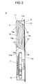
- FIG. 2 is a configuration view of the heat exchanger device according to Embodiment 1 of the present invention as seen from a cross section
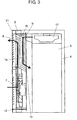
- FIG. 3 is a configuration view of the heat exchanger device and the heating element holder according to Embodiment 1 of the present invention as seen from a cross section
- FIG. 4 is a back elevational view of the heat exchanger device according to Embodiment 1 of the present invention
- FIG. 5 is an exploded view of a heat exchanger which is used in the heat exchanger device according to Embodiment 1 of the present invention
- FIG. 6 is a perspective view showing the heat exchanger which is used in the heat exchanger device according to Embodiment 1 of the present invention.
- heat exchanger device 6 As shown in FIGS. 2 to 4 , heat exchanger device 6 according to Embodiment 1, is provided with body case 11, air-blow fan 12 for a first environment, and heat exchanger 14.
- body case 11 is provided with first air intake port 7 and first discharge port 8 for a first environment which suck or discharge outside air, in a front surface 11a thereof, and second air intake port 9 and second discharge port 10 for a second environment which suck or discharge air in cabinet 4, in a back surface 11b thereof.
- Blower fan 12 for the first environment is provided in body case 11.
- Heat exchanger 14 carries out a heat exchange between the air for the first environment and the air for the second environment, in body case 11.
- Heat exchanger 14 includes, as shown in FIG. 5 , parallelogram columnar shaped multilayered body 14c having a plurality of parallelogram plate bodies 14d multilayered with predetermined distances
- air suction port 14a for the first environment and air suction port 14b for the second environment are provided in two opposed surfaces formed on the multilayered body 14c.
- Air blow-off port 14e for the first environment is provided in one of the other faces which are formed in multilayered body 14c by laminating parallelogram plate bodies 14d
- air blow-off port 14f for the second environment is provided in a surface opposed to the surface having air blow-off port 14e for the first environment.
- the perspective view in FIG. 6 shows a configuration in which parallelogram plate bodies 14d in FIG. 5 are formed as multilayered body 14c.
- air suction port 14a for the first environment is directed to air-blow fan 12
- air blow-off port 14e for the first environment is placed in contact with first discharge port 8 in body case 11
- air blow-off port 14f for the second environment is placed in contact with second discharge port 10 in body case 11.
- heat exchanger device 6 has chamber 16 formed between second air intake port 9 and air suction port 14b for the second environment.
- the heat exchanger device 6 has the chamber 16 which is formed between second air intake port 9 and air suction port 14b for the second environment, and can change a direction of the air blower by chamber 16. Accordingly, it is possible to arrange circulation fan 17 serving as an air-blow fan for the second environment in an outer portion of heat exchanger device 6, as mentioned below. Therefore, it is possible to downsize heat exchanger device 6.
- Multilayered body 14c of heat exchanger 14 is formed by superposing a plurality of parallelogram plate bodies 14d made of a synthetic resin with predetermined distances. Further, the surface provided with air suction port 14a for the first environment is adjacent to the surface provided with air blow-off port 14e for the first environment at first obtuse angle ⁇ 1, and the surface provided with air suction port 14b for the second environment is adjacent to the surface provided with the air blow-off port 14f for the second environment at second obtuse angle ⁇ 2.
- the surfaces of parallelogram plate bodies 14d forming multilayered body 14c are provided with a plurality of rectification walls 14g which divide the surfaces into a lane shape, as shown in FIGS. 2 and 5 .
- Parallelogram plate body 14d is formed into a parallelogram shape which is longer in a vertical direction, and rectification wall 14g is extended from one end of parallelogram plate body 14d serving as an inflow port toward the other end side.
- Rectification wall14g is formed into such a shape that is curved to one long side of the parallelogram short of the other end side, and is connected to an outflow port.
- a plurality of approximately L-shaped air blower lanes are formed on parallelogram plate bodies 14d by the plate-shaped rectification walls 14g as mentioned above.
- the short air blower lane is provided close to cabinet 4, and the long air blower lane is provided close to the external portion.
- the long air blower lane is provided close to cabinet 4, and the short air blower lane is provided close to the external portion.
- Heat exchanger 14 as mentioned above is configured such that a bottom surface is formed as an air inflow port close to the external portion, that is, air suction port 14a for the first environment, and each of air outflow ports close to the external portion is connected to first discharge port 8. Further, in heat exchanger 14, a top plate is formed as an inflow port close to inside air, that is, air suction port 14b for the second environment, and each of air outflow ports close to cabinet 4 is connected to second discharge port 10.
- air-blow fan 12 for the external air is provided at such a position as to feed in the air toward air suction port 14a for the first environment.
- air suction port 14b for the second environment serves as an inclined plane by itself, and chamber 16 is formed between it and the suction port of the air in cabinet 4, that is, second air intake port 9.
- the air sucked from the inner side of cabinet 4 changes its flow direction by passing through chamber 16, and is sucked into suction port 14b for the second environment.
- a back surface of heat exchanger device 6 is covered by body case 11, and is configured such that second air intake port 9, heat exchanger 14, second discharge port 10, and air-blow fan 12 are arranged from an upper portion.
- the cold external air is sucked from first air intake port 7 by an operation of air-blow fan 12, and is fed to air suction port 14a for the first environment of heat exchanger 14.
- heat exchanger 14 a heat exchange is carried out between the cold external air and the air in high temperature cabinet 4.
- the cooled air in the cabinet is blown out of second discharge port 10 into cabinet 4, and the external air is discharged to the external portion again from first discharge port 8.
- the air blown from circulation fan 17 in cabinet 4 passes through chamber 16 and flows into air suction port 14b for the second environment of heat exchanger 14 directed to second air intake port 9 side, by using heat exchanger 14 in which its cross section is formed into the parallelogram shape. Accordingly, the air which is heated in cabinet 4 efficiently flows into heat exchanger 14.
- heat exchanger 14 uses the plate body in which the cross sectional shape is the parallelogram shape, a bending angle is smaller in the air blower lane in the inner portion, and a pressure loss can be held down. Further, since the air blowing of the air in cabinet 4 is carried out by using circulation fan 17 provided in cabinet 4, it is possible to hold down a size of body case 11.
- FIG. 7 is a configuration view of the heat exchanger device according to Embodiment 1 of the present invention as seen from an exploded cross section
- FIG. 8 is a perspective view relating to a cover assembly of the heat exchanger device according to Embodiment 1 of the present invention.
- body case 11 comprises back plate 11d in a back surface side of frame body 11c to which front surface 11a and back surface 11b are open, and box body 11e which has an opening in back plate 11d side, and is provided close to front surface 11a of body case 11.
- a flange (not shown) protruding to an inner peripheral side is provided in a periphery, and is bonded to back plate 11d according to a screwing or the like.
- box body 11e is provided with first air intake port 7 and first discharge port 8.
- First air intake port 7 forms orifice 11f provided in such a manner as to protrude into an impeller of air-blow fan 12.
- back plate 11d is provided with air-blow fan 12 provided with second air intake port 9, second discharge port 10 and the motor.
- body case 11 comprises frame body 11c, front plate 11h provided close to front surface 11a of frame body 11c, and back plate 11d provided close to the back surface side of frame body 11c. Further, back plate 11d is provided with second air intake port 9, and second discharge port 10, and is configured such that air-blow fan 12 is fixed thereto.
- Packing is attached to a periphery close to box body 11e in an inner surface side of second discharge port 10 provided in back plate 11d. Further, guide wall 11g is provided around back plate 11d in a manner to come into contact with an outer periphery of box body 11e. Guide wall 11g is made higher than a height of orifice 11f provided close to box body 11e. Heat exchanger 14 is installed in such a manner as to be mounted on rail-shaped stand 19a and stand 19b provided in box body 11e, as shown in FIG. 7 .
- heat exchanger device 6 according to Embodiment 1 is configured such that stands 19a and 19b mounting heat exchanger 14 thereon are provided in box body 11e.
- heat exchanger 14 is precisely positioned, and is firmly fixed to frame body 11c.
- heat exchanger 14 is mounted on stands 19a and 19b, and the flanges provided in back plate 11d and box body 11e are bonded thereto.
- guide wall 11g is higher than the height of orifice 11f. Accordingly, even in the case that the bonding work is carried out while box body 11e is shifted, the flange surface of box body 11e and guide wall 11g come into contact with each other, whereby the impeller of air-blow fan 12 does not come into contact with orifice 11f, and is not damaged.
- the packing is elastically attached closely to second discharge port 10 of heat exchanger 14, thereby carrying out a fixation of heat exchanger 14 and a leakage prevention of the air from the outflow port.
- heat exchanger device 6 is provided with cover 21 which further includes louver 20 in an outer side of body case 11.
- Cover 21 is fixed by flange to back plate 11d in such a manner as to cover box body 11e.
- cover 21 is attached to door 22 of cabinet 4 from an inner face side.
- door 22 is opened, and body case 11 is detached from the inner side.
- the back surface side of frame body 11c constructing box body 11e is formed into the flange shape protruding to the inner peripheral side, and the packing is attached to the periphery close to the inner surface of second discharge port 10 provided in back plate 11d. Further, second discharge port 10 and air blow-off port 14f for the second environment are closely attached, at a time of fixing frame body 11c and back plate 11d to the flange.
- a peripheral edge portion of back plate 11d is provided with guide wall 11g in a manner to come along an outer periphery of frame body 11c.
- front plate 11h is provided with orifice 11f which leads to the suction port of air-blow fan 12, and guide wall 11g is configured to be higher than the height of orifice 11f.
- cover 21 fixed to back plate 11d and the flange in a manner to cover box body 11e, and cover 21 has louver 20 formed in the front surface side thereof.
- Embodiment 2 According to the present invention with reference to FIGS. 9 to 11 .
- FIG. 9 is a perspective view of a heat exchanger device according to Embodiment 2 of the present invention
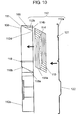
- FIG. 10 is a configuration view of an exploded cross section of the heat exchanger device according to Embodiment 2 of the present invention
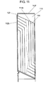
- FIG. 11 is a configuration view of an enlarged cross section of a heat exchanger portion of the heat exchanger device according to Embodiment 2 of the present invention. In this case, the description thereof may sometimes be omitted, with regard to the same components as those of Embodiment 1.
- body case 112 comprises back plate 112a in a back surface side of a frame body in which a front surface and a rear face are open, and box body 112b having an opening in a side of back plate 112a, and is provided in a front surface side of body case 112 (which may be expressed as a front surface side of the frame body).
- Box body 112b comprises scroll casing 112c which is molded by resin covering air-blow fan 113, and rectangular parallelepiped case 131 which covers heat exchanger 114 and is made of a metal.
- Wedge shaped depression 112d having a peak in the back surface side is provided in a side surface of box body 112b.
- Depression 112d bulges to an inner surface side of box body 112b as it is, and forms a wedge shaped protruding portion, although an illustration is omitted.
- An upper side of the wedge shaped protruding portion serves as support stand 118a supporting heat exchanger 114 in its lower side.
- support stand 118a comes to a side provided diagonally so as to descend toward back plate 112a side of box body 112b in such a manner as to be along an inclined lower surface of heat exchanger 114.
- support stand 118b is provided in such a manner as to connect end portions in a front surface side of support stand 118a.
- Support stand 118b is formed into a rail shape (not shown) protruding to an inner surface side of box body 112b, and is configured to support the front surface side of heat exchanger 114 from its lower side.
- Heat exchanger 114 shown in FIG. 10 is configured, in the same manner as Embodiment 1, such that approximately parallelogram plate bodies are laminated.
- cover 115 serving as a decorative laminated sheet is provided, in the same manner as Embodiment 1, in a front surface side of the heat exchanger device.
- Cover 115 is provided with a louver (not shown) for introducing the air in a portion which is opposed to first air intake port 108, and a louver (not shown) for discharging the air in a portion which is opposed to first discharge port 109.
- partition 119 is provided in a horizontal direction around box body 112b, between first discharge port 109 and a lower surface (first inflow port 114a), in a portion which comes to an outer hull of heat exchanger 114. Partition 119 comes into contact with an inner surface of cover 115 so as to divide an upper portion (close to first discharge port 109) and a lower portion (close to first air intake port 108).
- back plate 112a is provided with heat exchanger pressing projection 121 in a horizontal direction, in such a manner as to press heat exchanger 114 to a front surface side.
- a motor mounting portion of air-blow fan 113 is provided with depression 122 for a motor in such a manner as to protrude to an outer side.
- top surface protrusion 123 set in such a manner as to press to an inner side of box body 112b is provided in a boundary portion between top surface 112f of box body 112b and a front surface, that is, in a side close to a front surface side of top surface 112f.
- a top portion of heat exchanger 114 is brought into contact with a corner portion close to a front surface side, and chamber 116 is formed between top surface 112f of box body 112b and second inflow port 114b of heat exchanger 114.
- partition 119 is provided in such a manner as to separate between first air intake port 108 and first discharge port 109, it is possible to prevent a shortcut between an intake air and a discharge air.
- top surface protrusion 123 forms chamber 116 which secures a distance between the top surface of box body 112b and second inflow port 114b. Accordingly, the air sucked from second air intake port 110 efficiently flows to second inflow port 114b.
- a drive base plate for driving air-blow fan 113 is attached to an outer portion of body case 112. Accordingly, since heat generated from the drive base plate is hard to be conducted to the air which is circulated in heat exchanger 114, and does not deteriorate heat exchange efficiency, it is possible to reduce an influence given to the heat exchange efficiency.
- the heat exchanger device is provided with body case 112, air-blow fan 113 for the first environment, and heat exchanger 114.
- body case 112 is provided with first air intake port 108 and first discharge port 109 for the first environment which suck or discharge the outside air, in a front surface thereof, and second air intake port 110 and second discharge port 111 for the second environment which suck or discharge the air in the cabinet, in a back surface thereof.
- Air blower 113 for the first environment is provided in body case 112.
- Heat exchanger 114 carries out a heat exchange between the air for the first environment and the air for the second environment, in body case 112.
- Heat exchanger 114 is configured such as to include a multilayered body having a plurality of parallelogram plate bodies multilayered with predetermined distances, in the same manner as Embodiment 1.
- the air suction port for the first environment and the air suction port for the second environment are provided in two opposed surfaces formed thereon.
- Air blow-off port 1 for the first environment is provided in one of the other surfaces formed thereon, and the air blow-off port for the second environment is provided in the surface opposed to the surface provided with the air blow-off port for the first environment.
- the surface provided with the air suction port for the first environment is directed to air-blow fan 113, and the air blow-off port for the first environment is placed in contact with first discharge port 109 in body case 112, and the air blow-off port for the second environment is placed in contact with second discharge port 111 in body case 112.
- the heat exchanger device has chamber 116 formed between second air intake port 110 and the air suction port for the second environment.
- body case 112 comprises box body 112b having an opening in a back surface side thereof, and back plate 112a provided on a back surface side of box body 112b.
- box body 112b comprises scroll casing 112c portion formed of a resin material covering the portion having air-blow fan 113 arranged, and the rectangular parallelepiped portion formed of a metal material covering heat exchanger 114.
- scroll casing 112c having such a shape as to take into consideration the shape of air-blow fan 113 and the air flow, and heat exchanger 114 can be covered by a cover which is solid and has a good heat conduction. Therefore, it is possible to achieve a compact heat exchanger device in which the heat exchange efficiency is high.
- box body 112b is provided with rail shaped support stands 118a and 118b which come into contact with a periphery of the first environment air suction port of heat exchanger 114.
- box body 112b is provided with a wedge shaped protruding portion on an inner wall surface thereof by forming wedge shaped depression 112d having a peak in a back surface side thereof, and an upper side of the wedge shaped protruding portion constitutes a part of support stands 118a and 118b of heat exchanger 114.
- box body 112b is provided with a protrusion on an inner portion thereof where box body 112b is pressed inward at the boundary between top surface 112f of box body 112b and the front surface, and the peak portion of heat exchanger 114 is configured to be brought into contact with a corner portion formed by the protrusion and the front surface of box body 112b.
- back plate 112a is configured to have a projection provided in a manner to press heat exchanger 114 against the front surface side.
- back plate 112a is configured to be provided with a depression for mounting a motor for driving air-blow fan 113.
- FIG. 12 is a perspective view of a circulation fan portion of a heat exchanger device according to Embodiment 3 of the present invention
- FIG. 13 is a perspective view obtained by cutting a part of the circulation fan portion of the heat exchanger device according to Embodiment 3 of the present invention
- FIG. 14 is a configuration view of an exploded cross section of the circulation fan portion of the heat exchanger device according to Embodiment 3 of the present invention
- FIG. 15 is an exploded perspective view of the circulation fan portion of the heat exchanger device according to Embodiment 3 of the present invention.
- circulation fan 117 is set in box type fan case 131 provided with suction port 124 for a first environment in a bottom surface so as to configure circulation fan unit 130.
- Fan unit discharge port 137 is provided in a side surface of fan case 131, and is connected to second air intake port 9 of heat exchanger device 6 shown in FIG. 1 .
- Fan case 131 comprises box body 138 which is constituted by a top surface and side surfaces, and bottom plate 139 which constitutes a top surface. One of the side surfaces of box body 138 serves as fan unit discharge port 137.
- motor 127 of circulation fan 117 is attached to the top surface of box body 138, however, a mounting position of a housing is provided with motor mounting portion 132 which is protruded to an outer side. Further, a periphery of motor mounting portion 132 serving as a mounting position of motor 127 is provided with step portion 133 which is protruded to an outer side in such a manner as to fix a mounting device of motor 127.
- FIG. 14 is a vertical cross sectional view of a segmentation cross section at the time of exploding circulation fan unit 130.
- Circulation fan 117 is attached to motor fixing bracket 126 and is thereafter fixed to box body 138.
- Step portion 133 is formed in conformity to motor fixing bracket 126.
- Drive base plate 128 on which a circuit for driving motor 127 is mounted is attached to motor fixing bracket 126.
- Bottom plate 139 is provided with bottom plate partition plate 134 which divides an area in which drive base plate 128 is provided, and an area in which circulation fan 117 is provided and a blowing air circulates.
- a periphery of bottom plate 139 is provided with joining portion 135 which is bent at an acute angle towards box body 138 side.
- bonding flange 136 coming into surface contact with joining portion 135 is provided in box body 138 side, in such a manner as to be bent inward.
- an upper portion of circulation fan unit 130 can secure a mounting strength of circulation fan 117 by box body 138 provided with a side surface. Further, at the time of maintenance, it can be carried out by setting bottom plate 139 side to an upper side, and detaching bottom plate 139. Further, in box body 138, a strength of the top surface can be secured by step portion 133 for attaching motor fixing bracket 126, and motor mounting portion 132 serving as the protruding portion. Further, since drive base plate 128 serving as a heat generation portion and a section of circulation fan 117 serving as an air-blow path are separated by bottom plate partition plate 134, heat is hard to be conducted to a circulation wind path.
- the heat exchanger device is the heat exchanger device having the same configuration as Embodiments 1 and 2, and is provided with body case 112, air-blow fan 113 for the first environment, and heat exchanger 114.
- Heat exchanger 114 is configured to include the multilayered body having a plurality of plate bodies multilayered with predetermined distances, in the same manner as Embodiment 2.
- the surface provided with the air suction port for the first environment is directed to air-blow fan 113, the air blow-off port for the first environment is placed in contact with first discharge port 109 in body case 112, and the blow-off port for the second environment is placed in contact with second discharge port 111 in body case 112.
- the heat exchanger device has chamber 116 which is formed between second air intake port 110 and the air suction port for the second environment.
- body case 112 comprises box body 138 having an opening in a back surface side thereof, and back plate 112a provided on a back surface side of box body 138.
- a heating element holder comprises heat exchanger device 6, cabinet 4, and circulation fan 117 which have been described in Embodiments 1 to 3 as shown in FIG. 1 .
- cabinet 4 forms the second environment provided with the heat generating body in the inner portion.
- circulation fan 117 is provided in the top surface of cabinet 4, and conveys the air in cabinet 4 to the air suction port for the second environment in heat exchanger device 6.
- fan case 131 receiving circulation fan 117 therein comprises box body 138 in which a frame body and top surface 112f are integrally formed, and bottom plate 139 provided with the air suction port sucking the air in cabinet 4.
- bottom plate of fan case 131 has a bent portion formed by bending a periphery thereof at an acute angle toward box body 138 side, and box body 138 side of fan case 131 has bonding flange 136 formed by bending the periphery of bottom plate side inward in a manner to bond to the bent portion of bottom plate.
- the upper portion of circulation fan unit 130 can secure a mounting strength of circulation fan 117 by box body 138 provided with the side surface. Further, at the time of maintenance, it can be carried out by setting bottom plate 139 side to the upper side, and detaching bottom plate 139.
- the air blow-off port to heat exchanger device 6 is provided in one of the side surfaces of box body 138 of fan case 131, and bonding flange 136 in the periphery of the air blow-off port connecting to heat exchanger device 6.
- the upper portion of circulation fan unit 130 can secure the mounting strength of circulation fan 117, by box body 138 provided with the side surface. Further, at the time of maintenance, it can be carried out by setting bottom plate 139 side to the upper side, and detaching bottom plate 139.
- FIG. 16 is a perspective view of a heat exchanger device according to Embodiment 4 of the present invention
- FIG. 17 is a perspective view of a scroll casing of the heat exchanger device according to Embodiment 4 of the present invention
- FIG. 18 is a perspective view of a motor fixing plate of the heat exchanger device according to Embodiment 4 of the present invention
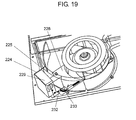
- FIG. 19 is a perspective view showing an air-blow fan mounting configuration of the heat exchanger device according to Embodiment 4 of the present invention.
- FIG. 16 is a perspective view of a heat exchanger device according to Embodiment 4 of the present invention
- FIG. 17 is a perspective view of a scroll casing of the heat exchanger device according to Embodiment 4 of the present invention
- FIG. 18 is a perspective view of a motor fixing plate of the heat exchanger device according to Embodiment 4 of the present invention
- FIG. 19 is a perspective view showing an air-blow fan mounting configuration of the heat exchanger device according to Embodiment
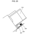
- FIG. 20 is a plan view obtained by enlarging a main part of an installation of the air-blow fan of the heat exchanger device according to Embodiment 4 of the present invention
- FIG. 21 is a cross sectional view showing a configuration to which a motor of the heat exchanger device according to Embodiment 4 of the present invention is attached.
- air-blow fan 213 With reference to FIGS. 16 to 18 .
- body case 212 comprises back plate 212a close to a back surface side, and box body 212b which is open to back plate 212a side, and is provided in a front surface side of body case 212 (which also corresponds to a front surface side of a frame body).
- Box body 212b comprises scroll casing 221 which is molded with a resin covering air-blow fan 213, and rectangular parallelepiped body case 212 which covers heat exchanger 214 and is made of a metal.
- Scroll casing 221 comprises suction port side plate 221a provided with an ambient air suction port in a front surface side thereof, side plate 221b opposed to the suction side, and scroll plate 221c. In this case, side plate 221b opposed to the suction side may used in common with back plate 212a.
- Scroll plate 221c is integrally provided with control box 224 which protrudes out in a diametrical direction.
- a control circuit (not shown) driving motor 222 is embedded in control box 224.
- the control box 224 is partitioned from a space provided with impeller 223 by partition wall 225.
- Partition wall 225 serves as a scroll plate in a section provided with impeller 223.
- the interior portion of the control box 224 is separated a base plate area 226 and an isolation area 227.
- Base plate area 226 is provided in an outer side in a diametrical direction of control box 224, and a base plate mounting the control circuit is stored therein. Isolation area 227 is provided between the section provided with impeller 223 and base plate area 226.
- motor 222 is attached to motor fixing plate 228 close to back plate 212a.
- Motor fixing plate 228 is formed into such a shape as to close a back surface side (back plate 212a side) of control box 224, and control base plate accommodation box 229 mounting the control circuit thereon is provided in a portion closing base plate area 226 in control box 224.
- Motor fixing plate 228 is attached to base plate 212a.
- Scroll casing 221 is attached in a state where motor fixing plate 228 and back plate 212a are fixed.
- Control base plate accommodation box 229 is received in base plate area 226.
- Motor 222 is fixed in such a manner as to be sandwiched by motor fixing plate 228 and motor cover 230.
- Motor cover 230 comprises a portion which is open in a rotating shaft portion and presses motor 222, and a leg portion which is connected to motor fixing plate 228.
- Motor fixing plate 228 is provided with a slit to which the leg portion is fitted, and can be easily fixed and released by rotating motor cover 230 around the rotating shaft.
- the leg portion is provided with wiring fixing portion 231. which is fixed through a wiring for driving motor 222, thereby facilitating the fixation of motor 222.
- the wiring for driving motor 222 that is, lead wire 233 is temporarily put out of scroll plate 221c to scroll casing 221. Thereafter, it is guided from notch 232 provided in base plate area 226 of control box 224 into the control circuit. Further, lead wire 233 is traced into a bend provided in an end portion of motor fixing plate 228, that is, lead wire protection portion 234.
- vibration proof rubber 235 is provided between motor 222 and motor fixing plate 228, and makes a vibration of motor 222 hard to be transmitted to back plate 212a.
- control circuit for driving motor 222 is separated from the area through which the ambient air passes, that is, the area in which impeller 223 is provided. Accordingly, it is possible to obtain an air blower which is not exposed to a dust mixed into the ambient air and has high reliability.
- control circuit is fixed to motor fixing plate 228 integrally with motor 222, it is possible to easily carry out a wiring work and a thereafter assembling work. Further, isolation area 227 is provided between base plate area 226 and the area in which impeller 223 is provided. Accordingly, the heat generation of the control circuit is hard to be conducted to the blown air.
- isolation area 227 is provided, and the wiring for driving motor 222 is not passed through isolation area 227, the configuration is made such that the dust, a water drop and the like are hard to enter into the control circuit side.
- the heat exchanger device using air-blow fan 213 as mentioned above does not directly come into contact with the control circuit even if it sucks the ambient air including the dust and the like from the first air intake port serving as the ambient air intake port. Accordingly, an influence applied to the control circuit by the dust or the like is hard to be generated.
- the heat exchanger device is the heat exchanger device having the same configuration as Embodiments 1 to 3, and body case 212, air-blow fan 213 for the first environment, and heat exchanger 214.
- Heat exchanger 214 is configured to include the multilayered body having a plurality of plate bodies multilayered with predetermined distances, in the same manner as Embodiment 1.
- the surface provided with the air suction port for the first environment is directed to air-blow fan 213, and the air blow-off port for the first environment is placed in contact with the first discharge port formed in body case 212, and the air blow-off port for the second environment is placed in contact with the second discharge port formed in body case 212.
- the heat exchanger device has a chamber formed between the second air intake port and the air suction port for the second environment.
- body case 212 comprises the box body having an opening in a back surface side thereof, and back plate 212a provided on a back surface side of the box body, and air-blow fan 213 is configured as a centrifugal air blower.
- centrifugal air blower comprises motor 222 and impeller 223 encased in scroll casing 221 having suction port side plate 221a provided with an ambient air suction port, side plate 221b opposed to the suction side and scroll plate 221c.
- scroll plate 221c is provided with control box 224 protruding in a diametrical direction, and containing a control circuit for driving motor 222.
- Control box 224 is separated from a space housing impeller 223.
- scroll casing 221 is configured such that suction port side plate 221a and scroll plate 221c are integrally molded by the resin so as to be fixed to side plate 221b opposed to the suction side.
- motor 222 is configured to be fixed to the fixing plate provided on the side opposite the ambient air suction port, and the control circuit is configured to be fixed onto the fixing plate.
- motor 222 is configured to be fixed by the fixing plate, and motor cover 230 which is formed so as to sandwich motor 222 with the fixing plate.
- motor cover 230 has a fixing hole for fixing wiring fixing portion 231 provided in motor 222.
- scroll casing 221 is configured to be integrally provided with control box 224.
- control circuit is not exposed to the air including the dust, and it is possible to obtain a centrifugal air blower having high reliability. As a result, it is possible to realize a heat exchanger device having high reliability. Further, it is possible to downsize the heat exchanger device.
- scroll casing 221 is provided with a partition plate separating the space of impeller 223 from a section having control box 224.
- control circuit is not exposed to the air including the dust, and it is possible to obtain a centrifugal air blower having high reliability. As a result, it is possible to realize a heat exchanger device having high reliability. Further, it is possible to downsize the heat exchanger device.
- scroll casing 221 is configured to be provided with isolation area 227 separating the space of impeller 223 from the section having control box 224.
- control circuit is not exposed to the air including the dust, and it is possible to obtain a centrifugal air blower having high reliability. As a result, it is possible to realize a heat exchanger device having high reliability. Further, it is possible to downsize the heat exchanger device.
- control circuit and motor 222 is routed from the space impeller 223 into control box 224 via the outside of scroll casing 221 without passing through the isolation area 227.
- the heating element holder comprises heat exchanger device 6, cabinet 4, and the circulating fan which have been described in Embodiments 1 to 3 as shown in FIG. 1 .
- cabinet 4 forms a second environment provided with a heat generating body in its inner portion.
- the circulating fan is provided on a top surface of cabinet 4 for delivering the air in cabinet 4 to the air suction port for the second environment of heat exchanger device 6.
- the fan case enclosing the circulating fan comprises a box body integrally formed by a frame body and top surface 112f, and bottom plate 139 provided with the air suction port for sucking the air in cabinet 4.
- the circulation fan serving as the air-blow fan for the second environment in the outer portion of the heat exchanger device, and it is possible to downsize the heat exchanger device. Therefore, it becomes extremely useful for the cooling equipment, for example, in the base station of the communication equipment having a limited installation area, and the other outdoor installed equipment.
Landscapes
- Engineering & Computer Science (AREA)
- Aviation & Aerospace Engineering (AREA)
- Physics & Mathematics (AREA)
- Thermal Sciences (AREA)
- Microelectronics & Electronic Packaging (AREA)
- Chemical & Material Sciences (AREA)
- Combustion & Propulsion (AREA)
- Mechanical Engineering (AREA)
- General Engineering & Computer Science (AREA)
- Cooling Or The Like Of Electrical Apparatus (AREA)
- Heat-Exchange Devices With Radiators And Conduit Assemblies (AREA)
- Structures Of Non-Positive Displacement Pumps (AREA)
Abstract
Description
- The present invention relates to a heat exchanger device and a heating element holder using the same.
- A cellular phone base station, for example, is sometimes expressed as a heating element because it has a large current flow of several tens of amperes. It is also considered a heating element having high electric power consumption in light of its electric power consumption. Accordingly, cooling the generated heat is extremely important in order to stabilize the performance of the base station of the cellular phone. The cellular phone base station as mentioned above is provided with the following configuration for carrying out its cooling.
-
FIG. 22 is a cross sectional view schematically showing a configuration of a conventional heat exchanger device. - The cellular phone base station is configured to include an electronic circuit and the like, and is generally arranged in a casing such as a cabinet protecting them from an external natural environment. The cabinet houses a transmitting and receiving portion serving as a protection heating element in its inner portion, for example, and is configured such that
heat exchanger device 301 as shown inFIG. 22 is provided in an opening portion of the cabinet. Further, as shown inFIG. 22 ,heat exchanger device 301 is structured to be provided withbody case 311,first air blower 312 andsecond air blower 313 provided inbody case 311, andheat exchanger 314 carrying out heat exchange between outdoor air and air in the cabinet (not shown) in body case 311 (refer toPatent Document 1 which shows similar technology). In this case,body caste 311 hasfirst suction port 307 sucking the outdoor air andfirst discharge port 308 discharging the outdoor air, andsecond suction port 309 sucking the air in the cabinet andsecond discharge port 310 discharging the air into the cabinet.First air blower 312 blows the ambient air toheat exchanger device 301, andsecond air blower 313 blows the air inside the cabinet toheat exchanger device 301. - Conventional
heat exchanger device 301 mentioned above has a configuration in which two air blowers, that is,first air blower 312 blowing the ambient air andsecond air blower 313 blowing the air inside the cabinet, andheat exchanger 314 are housed in onebody case 311, and hencebody case 311 itself becomes large. On the other hand, the base station of the cellular phone is advanced in its downsizing, and it is strongly required to reduce the size of the heat exchanger device main body. - Patent Document 1: Unexamined Japanese Patent Publication No.
2000-161875 - Accordingly, an object of the present invention is to downsize a heat exchanger device.
- The heat exchanger device according to the present invention includes: a body case provided with a first air intake port and a first discharge port for a first environment in a front surface thereof, and a second air intake port and a second discharge port for a second environment in a back surface thereof; an air-blow fan for the first environment provided in the body case; and a heat exchanger inside the body case for exchanging heat between the air in the first environment and the air in the second environment, wherein the heat exchanger includes a multilayered body having a plurality of parallelogram plate bodies multilayered with predetermined distances, the multilayered body having the multilayered parallelogram plate bodies is provided with an air suction port for the first environment and an air suction port for the second environment in two opposed surfaces thereof, the multilayered body having the multilayered parallelogram plate bodies is further provided with an air blow-off port for the first environment in one of the other surfaces formed thereon, and an air blow-off port for the second environment in another surface opposed to the surface having the air blow-off port for the first environment, the surface provided with the air suction port for the first environment is directed to the air-blow fan, the air blow-off port for the first environment is placed in contact with the first discharge port formed in the body case and the air blow-off port for the second environment is placed in contact with the second discharge port formed in the body case, and the heat exchanger has a chamber formed between the second air intake port and the air suction port for the second environment.
- With this configuration, since it has the chamber which is formed between the second air intake port and the air suction port for the second environment, and can change a direction of the air blower by the chamber, it is possible to arrange the air-blow fan for the second environment in an outer portion of the heat exchanger device. Therefore, it is possible to downsize the heat exchanger device.
- Further, a heating element holder according to the present invention comprises using the heat exchanger device described above.
- With this configuration, by using the downsized heat exchanger device, a downsized heating element holder can be realized. Further, by using the heat exchanger device having the chamber, it becomes possible to select a place where the air-blow fan for the second environment is installed, enlarge a design freedom of a parts layout, and further downsize the heating element holder.
-
-
FIG. 1 is a perspective view showing an installation example of a heating element holder using a heat exchanger device according toEmbodiment 1 of the present invention. -
FIG. 2 is a configuration view of the heat exchanger device according toEmbodiment 1 of the present invention as seen from a cross section. -
FIG. 3 is a configuration view of the heat exchanger device and the heating element holder according toEmbodiment 1 of the present invention as seen from a cross section. -
FIG. 4 is a back elevational view of the heat exchanger device according toEmbodiment 1 of the present invention. -
FIG. 5 is an exploded view of a heat exchanger which is used in the heat exchanger device according toEmbodiment 1 of the present invention. -
FIG. 6 is a perspective view showing the heat exchanger which is used in the heat exchanger device according toEmbodiment 1 of the present invention. -
FIG. 7 is a configuration view of the heat exchanger device according toEmbodiment 1 of the present invention as seen from an exploded cross section. -
FIG. 8 is a perspective view relating to a cover assembly of the heat exchanger device according toEmbodiment 1 of the present invention. -
FIG. 9 is a perspective view of a heat exchanger device according toEmbodiment 2 of the present invention. -
FIG. 10 is a configuration view of an exploded cross section of the heat exchanger device according toEmbodiment 2 of the present invention. -
FIG. 11 is a configuration view of an enlarged cross section of a heat exchanger portion of the heat exchanger device according toEmbodiment 2 of the present invention. -
FIG. 12 is a perspective view of a circulation fan portion of a heat exchanger device according toEmbodiment 3 of the present invention. -
FIG. 13 is a perspective view obtained by cutting a part of the circulation fan portion of the heat exchanger device according toEmbodiment 3 of the present invention. -
FIG. 14 is a configuration view of an exploded cross section of the circulation fan portion of the heat exchanger device according toEmbodiment 3 of the present invention. -
FIG. 15 is an exploded perspective view of the circulation fan portion of the heat exchanger device according toEmbodiment 3 of the present invention. -
FIG. 16 is a perspective view of a heat exchanger device according toEmbodiment 4 of the present invention. -
FIG. 17 is a perspective view of a scroll casing of the heat exchanger device according toEmbodiment 4 of the present invention: -
FIG. 18 is a perspective view of a motor fixing plate of the heat exchanger device according toEmbodiment 4 of the present invention. -
FIG. 19 is a perspective view showing an air-blow fan mounting configuration of the heat exchanger device according toEmbodiment 4 of the present invention. -
FIG. 20 is a plan view obtained by enlarging a main part of an installation of the air-blow fan of the heat exchanger device according toEmbodiment 4 of the present invention. -
FIG. 21 is a cross sectional view showing a configuration of the heat exchanger device according toEmbodiment 4 of the present invention to which a motor is attached. -
FIG. 22 is a cross sectional view schematically showing a configuration of a conventional heat exchanger device. - A description will be given below of an embodiment according to the present invention with reference to the accompanying drawings. In the following drawings, since like components are denoted by like reference marks, and the description thereof may sometimes be omitted.
-
FIG. 1 is a perspective view showing an installation example of a heating element holder using a heat exchanger device according toEmbodiment 1 of the present invention. - As shown in
FIG. 1 , a cellularphone base station 3 is provided onrooftop 2 of building 1 housing offices and the like.Base station 3 includes, for example, box-like cabinet 4, transmitting and receivingportion 5 provided in thecabinet 4, and aheat exchanger device 6 provided in the front opening portion ofcabinet 4. In this case,heat exchanger device 6 is installed in the back surface ofdoor 22, and can move together withdoor 22 so as to freely open and close. -
FIG. 2 is a configuration view of the heat exchanger device according toEmbodiment 1 of the present invention as seen from a cross section, andFIG. 3 is a configuration view of the heat exchanger device and the heating element holder according toEmbodiment 1 of the present invention as seen from a cross section. Further,FIG. 4 is a back elevational view of the heat exchanger device according toEmbodiment 1 of the present invention.FIG. 5 is an exploded view of a heat exchanger which is used in the heat exchanger device according toEmbodiment 1 of the present invention, andFIG. 6 is a perspective view showing the heat exchanger which is used in the heat exchanger device according toEmbodiment 1 of the present invention. - As shown in
FIGS. 2 to 4 ,heat exchanger device 6 according toEmbodiment 1, is provided withbody case 11, air-blow fan 12 for a first environment, andheat exchanger 14. In this case,body case 11 is provided with firstair intake port 7 andfirst discharge port 8 for a first environment which suck or discharge outside air, in afront surface 11a thereof, and secondair intake port 9 andsecond discharge port 10 for a second environment which suck or discharge air incabinet 4, in aback surface 11b thereof. Blowerfan 12 for the first environment is provided inbody case 11.Heat exchanger 14 carries out a heat exchange between the air for the first environment and the air for the second environment, inbody case 11. -
Heat exchanger 14 includes, as shown inFIG. 5 , parallelogram columnar shapedmultilayered body 14c having a plurality ofparallelogram plate bodies 14d multilayered with predetermined distances Inheat exchanger 14,air suction port 14a for the first environment andair suction port 14b for the second environment are provided in two opposed surfaces formed on themultilayered body 14c. Air blow-offport 14e for the first environment is provided in one of the other faces which are formed inmultilayered body 14c by laminatingparallelogram plate bodies 14d, and air blow-offport 14f for the second environment is provided in a surface opposed to the surface having air blow-offport 14e for the first environment. In this case, the perspective view inFIG. 6 shows a configuration in whichparallelogram plate bodies 14d inFIG. 5 are formed asmultilayered body 14c. - Further, the surface provided with
air suction port 14a for the first environment is directed to air-blow fan 12, air blow-off port 14e for the first environment is placed in contact withfirst discharge port 8 inbody case 11 and air blow-off port 14f for the second environment is placed in contact withsecond discharge port 10 inbody case 11. Further,heat exchanger device 6 haschamber 16 formed between secondair intake port 9 andair suction port 14b for the second environment. - With this configuration, the
heat exchanger device 6 has thechamber 16 which is formed between secondair intake port 9 andair suction port 14b for the second environment, and can change a direction of the air blower bychamber 16. Accordingly, it is possible to arrangecirculation fan 17 serving as an air-blow fan for the second environment in an outer portion ofheat exchanger device 6, as mentioned below. Therefore, it is possible to downsizeheat exchanger device 6. -
Multilayered body 14c ofheat exchanger 14 is formed by superposing a plurality ofparallelogram plate bodies 14d made of a synthetic resin with predetermined distances. Further, the surface provided withair suction port 14a for the first environment is adjacent to the surface provided with air blow-off port 14e for the first environment at first obtuse angle θ1, and the surface provided withair suction port 14b for the second environment is adjacent to the surface provided with the air blow-off port 14f for the second environment at second obtuse angle θ2. - The surfaces of
parallelogram plate bodies 14d formingmultilayered body 14c are provided with a plurality ofrectification walls 14g which divide the surfaces into a lane shape, as shown inFIGS. 2 and5 .Parallelogram plate body 14d is formed into a parallelogram shape which is longer in a vertical direction, andrectification wall 14g is extended from one end ofparallelogram plate body 14d serving as an inflow port toward the other end side. Rectification wall14g is formed into such a shape that is curved to one long side of the parallelogram short of the other end side, and is connected to an outflow port. A plurality of approximately L-shaped air blower lanes are formed onparallelogram plate bodies 14d by the plate-shapedrectification walls 14g as mentioned above. - According to
heat exchanger 14 having such a configuration, with regard to the air for the second environment, the short air blower lane is provided close tocabinet 4, and the long air blower lane is provided close to the external portion. On the other hand, with regard to the air for the first environment, the long air blower lane is provided close tocabinet 4, and the short air blower lane is provided close to the external portion. -
Heat exchanger 14 as mentioned above is configured such that a bottom surface is formed as an air inflow port close to the external portion, that is,air suction port 14a for the first environment, and each of air outflow ports close to the external portion is connected tofirst discharge port 8. Further, inheat exchanger 14, a top plate is formed as an inflow port close to inside air, that is,air suction port 14b for the second environment, and each of air outflow ports close tocabinet 4 is connected tosecond discharge port 10. - Further, air-
blow fan 12 for the external air is provided at such a position as to feed in the air towardair suction port 14a for the first environment. In the inflow port of the air insidecabinet 4, that is,air suction port 14b for the second environment,air suction port 14b for the second environment serves as an inclined plane by itself, andchamber 16 is formed between it and the suction port of the air incabinet 4, that is, secondair intake port 9. The air sucked from the inner side ofcabinet 4 changes its flow direction by passing throughchamber 16, and is sucked intosuction port 14b for the second environment. - Further, as shown in
FIG. 4 , a back surface ofheat exchanger device 6 is covered bybody case 11, and is configured such that secondair intake port 9,heat exchanger 14,second discharge port 10, and air-blow fan 12 are arranged from an upper portion. - Next, a description will be given of an operation and a function of
heat exchanger device 6. The air raised to high temperature due to heat generated from the transmitting and receivingportion 5 incabinet 4 is fed intochamber 16 from secondair intake port 9 ofheat exchanger device 6 bycirculation fan 17 provided incabinet 4. In this case, an upper portion and a surrounding area ofheat exchanger device 6 are covered bycover 21. - On the other hand, the cold external air is sucked from first
air intake port 7 by an operation of air-blow fan 12, and is fed toair suction port 14a for the first environment ofheat exchanger 14. Inheat exchanger 14, a heat exchange is carried out between the cold external air and the air inhigh temperature cabinet 4. As a result, the cooled air in the cabinet is blown out ofsecond discharge port 10 intocabinet 4, and the external air is discharged to the external portion again fromfirst discharge port 8. - With such a configuration, the air blown from
circulation fan 17 incabinet 4 passes throughchamber 16 and flows intoair suction port 14b for the second environment ofheat exchanger 14 directed to secondair intake port 9 side, by usingheat exchanger 14 in which its cross section is formed into the parallelogram shape. Accordingly, the air which is heated incabinet 4 efficiently flows intoheat exchanger 14. - Further, since
heat exchanger 14 uses the plate body in which the cross sectional shape is the parallelogram shape, a bending angle is smaller in the air blower lane in the inner portion, and a pressure loss can be held down. Further, since the air blowing of the air incabinet 4 is carried out by usingcirculation fan 17 provided incabinet 4, it is possible to hold down a size ofbody case 11. - Next, a description will be given of an installation of
heat exchanger 14 inbody case 11.FIG. 7 is a configuration view of the heat exchanger device according toEmbodiment 1 of the present invention as seen from an exploded cross section, andFIG. 8 is a perspective view relating to a cover assembly of the heat exchanger device according toEmbodiment 1 of the present invention. - As shown in
FIGS. 7 and8 ,body case 11 comprises backplate 11d in a back surface side offrame body 11c to whichfront surface 11a and backsurface 11b are open, andbox body 11e which has an opening inback plate 11d side, and is provided close tofront surface 11a ofbody case 11. In the opening close to backplate 11d ofbox body 113, a flange (not shown) protruding to an inner peripheral side is provided in a periphery, and is bonded to backplate 11d according to a screwing or the like. Further,box body 11e is provided with firstair intake port 7 andfirst discharge port 8. Firstair intake port 7forms orifice 11f provided in such a manner as to protrude into an impeller of air-blow fan 12. - On the other hand, back
plate 11d is provided with air-blow fan 12 provided with secondair intake port 9,second discharge port 10 and the motor. - In other words,
body case 11 comprisesframe body 11c,front plate 11h provided close tofront surface 11a offrame body 11c, and backplate 11d provided close to the back surface side offrame body 11c. Further, backplate 11d is provided with secondair intake port 9, andsecond discharge port 10, and is configured such that air-blow fan 12 is fixed thereto. - Packing is attached to a periphery close to
box body 11e in an inner surface side ofsecond discharge port 10 provided inback plate 11d. Further,guide wall 11g is provided around backplate 11d in a manner to come into contact with an outer periphery ofbox body 11e.Guide wall 11g is made higher than a height oforifice 11f provided close tobox body 11e.Heat exchanger 14 is installed in such a manner as to be mounted on rail-shapedstand 19a and stand 19b provided inbox body 11e, as shown inFIG. 7 . - In other words,
heat exchanger device 6 according toEmbodiment 1 is configured such that stands 19a and 19b mountingheat exchanger 14 thereon are provided inbox body 11e. - With such a configuration,
heat exchanger 14 is precisely positioned, and is firmly fixed to framebody 11c. - At a time of assembling
heat exchanger device 6,heat exchanger 14 is mounted onstands back plate 11d andbox body 11e are bonded thereto. At this time, since a bonding work is carried out alongguide wall 11g, inbox body 11e, it is possible to easily carry out a normal positioning. Further,guide wall 11g is higher than the height oforifice 11f. Accordingly, even in the case that the bonding work is carried out whilebox body 11e is shifted, the flange surface ofbox body 11e and guidewall 11g come into contact with each other, whereby the impeller of air-blow fan 12 does not come into contact withorifice 11f, and is not damaged. At a time of the flanged joint betweenbox body 11e and backplate 11d, the packing is elastically attached closely tosecond discharge port 10 ofheat exchanger 14, thereby carrying out a fixation ofheat exchanger 14 and a leakage prevention of the air from the outflow port. - As shown in
FIG. 8 ,heat exchanger device 6 is provided withcover 21 which further includeslouver 20 in an outer side ofbody case 11.Cover 21 is fixed by flange to backplate 11d in such a manner as to coverbox body 11e. - In such a configuration, cover 21 is attached to door 22 of
cabinet 4 from an inner face side. At a time of maintenance ofheat exchanger device 6,door 22 is opened, andbody case 11 is detached from the inner side. - In other words, in the heat exchanger device according to
Embodiment 1, the back surface side offrame body 11cconstructing box body 11e is formed into the flange shape protruding to the inner peripheral side, and the packing is attached to the periphery close to the inner surface ofsecond discharge port 10 provided inback plate 11d. Further,second discharge port 10 and air blow-off port 14f for the second environment are closely attached, at a time of fixingframe body 11c and backplate 11d to the flange. - With this configuration, it is possible to securely fix
heat exchanger 14, and prevent the air from leaking from the outflow port. - Further, a peripheral edge portion of
back plate 11d is provided withguide wall 11g in a manner to come along an outer periphery offrame body 11c. - With this configuration, the heat exchanger device is easily assembled.
- Further,
front plate 11h is provided withorifice 11f which leads to the suction port of air-blow fan 12, and guidewall 11g is configured to be higher than the height oforifice 11f. - With this configuration, it is possible to easily assemble the heat exchanger device, and it is possible to rectify the flow of the air caused by air-
blow fan 12. - Further, cover 21 fixed to back
plate 11d and the flange in a manner to coverbox body 11e, and cover 21 haslouver 20 formed in the front surface side thereof. - With this configuration, it is possible to protect the configuration parts which are arranged in the inner portion of the heat exchanger device, and it is possible to smoothly suck and discharge the outside air.
- Next, a description will be given of
Embodiment 2 according to the present invention with reference toFIGS. 9 to 11 . -
FIG. 9 is a perspective view of a heat exchanger device according toEmbodiment 2 of the present invention, andFIG. 10 is a configuration view of an exploded cross section of the heat exchanger device according toEmbodiment 2 of the present invention.FIG. 11 is a configuration view of an enlarged cross section of a heat exchanger portion of the heat exchanger device according toEmbodiment 2 of the present invention. In this case, the description thereof may sometimes be omitted, with regard to the same components as those ofEmbodiment 1. - As shown in
FIGS. 9 and10 , inEmbodiment 2,body case 112 comprises backplate 112a in a back surface side of a frame body in which a front surface and a rear face are open, andbox body 112b having an opening in a side ofback plate 112a, and is provided in a front surface side of body case 112 (which may be expressed as a front surface side of the frame body).Box body 112b comprisesscroll casing 112c which is molded by resin covering air-blow fan 113, andrectangular parallelepiped case 131 which coversheat exchanger 114 and is made of a metal. Wedge shapeddepression 112d having a peak in the back surface side is provided in a side surface ofbox body 112b.Depression 112d bulges to an inner surface side ofbox body 112b as it is, and forms a wedge shaped protruding portion, although an illustration is omitted. An upper side of the wedge shaped protruding portion serves as support stand 118a supportingheat exchanger 114 in its lower side. In other words,support stand 118a comes to a side provided diagonally so as to descend towardback plate 112a side ofbox body 112b in such a manner as to be along an inclined lower surface ofheat exchanger 114. Further,support stand 118b is provided in such a manner as to connect end portions in a front surface side ofsupport stand 118a.Support stand 118b is formed into a rail shape (not shown) protruding to an inner surface side ofbox body 112b, and is configured to support the front surface side ofheat exchanger 114 from its lower side. -
Heat exchanger 114 shown inFIG. 10 is configured, in the same manner asEmbodiment 1, such that approximately parallelogram plate bodies are laminated. - Further, cover 115 (not shown) serving as a decorative laminated sheet is provided, in the same manner as
Embodiment 1, in a front surface side of the heat exchanger device. Cover 115 is provided with a louver (not shown) for introducing the air in a portion which is opposed to firstair intake port 108, and a louver (not shown) for discharging the air in a portion which is opposed tofirst discharge port 109. Inbox body 112b,partition 119 is provided in a horizontal direction aroundbox body 112b, betweenfirst discharge port 109 and a lower surface (first inflow port 114a), in a portion which comes to an outer hull ofheat exchanger 114.Partition 119 comes into contact with an inner surface of cover 115 so as to divide an upper portion (close to first discharge port 109) and a lower portion (close to first air intake port 108). - As shown in
FIG. 10 , backplate 112a is provided with heatexchanger pressing projection 121 in a horizontal direction, in such a manner as to pressheat exchanger 114 to a front surface side. Further, a motor mounting portion of air-blow fan 113 is provided withdepression 122 for a motor in such a manner as to protrude to an outer side. - As shown in
FIG. 11 ,top surface protrusion 123 set in such a manner as to press to an inner side ofbox body 112b is provided in a boundary portion betweentop surface 112f ofbox body 112b and a front surface, that is, in a side close to a front surface side oftop surface 112f. In thistop face protrusion 123, a top portion ofheat exchanger 114 is brought into contact with a corner portion close to a front surface side, andchamber 116 is formed betweentop surface 112f ofbox body 112b andsecond inflow port 114b ofheat exchanger 114. - With such a configuration, since an outer periphery of air-
blow fan 113 is formed asscroll casing 112c, it is possible to efficiently flow a wind towardfirst inflow port 114a. - Further, since
partition 119 is provided in such a manner as to separate between firstair intake port 108 andfirst discharge port 109, it is possible to prevent a shortcut between an intake air and a discharge air. - Further,
top surface protrusion 123forms chamber 116 which secures a distance between the top surface ofbox body 112b andsecond inflow port 114b. Accordingly, the air sucked from secondair intake port 110 efficiently flows tosecond inflow port 114b. - In this case, a drive base plate for driving air-
blow fan 113 is attached to an outer portion ofbody case 112. Accordingly, since heat generated from the drive base plate is hard to be conducted to the air which is circulated inheat exchanger 114, and does not deteriorate heat exchange efficiency, it is possible to reduce an influence given to the heat exchange efficiency. - In other words, the heat exchanger device according to the present invention is provided with
body case 112, air-blow fan 113 for the first environment, andheat exchanger 114. In this case,body case 112 is provided with firstair intake port 108 andfirst discharge port 109 for the first environment which suck or discharge the outside air, in a front surface thereof, and secondair intake port 110 andsecond discharge port 111 for the second environment which suck or discharge the air in the cabinet, in a back surface thereof.Air blower 113 for the first environment is provided inbody case 112.Heat exchanger 114 carries out a heat exchange between the air for the first environment and the air for the second environment, inbody case 112. -
Heat exchanger 114 is configured such as to include a multilayered body having a plurality of parallelogram plate bodies multilayered with predetermined distances, in the same manner asEmbodiment 1. Inheat exchanger 114, the air suction port for the first environment and the air suction port for the second environment are provided in two opposed surfaces formed thereon. Air blow-off port 1 for the first environment is provided in one of the other surfaces formed thereon, and the air blow-off port for the second environment is provided in the surface opposed to the surface provided with the air blow-off port for the first environment. - Further, the surface provided with the air suction port for the first environment is directed to air-
blow fan 113, and the air blow-off port for the first environment is placed in contact withfirst discharge port 109 inbody case 112, and the air blow-off port for the second environment is placed in contact withsecond discharge port 111 inbody case 112. Further, the heat exchanger device haschamber 116 formed between secondair intake port 110 and the air suction port for the second environment. - Further,
body case 112 comprisesbox body 112b having an opening in a back surface side thereof, and backplate 112a provided on a back surface side ofbox body 112b. - With this configuration, since it is possible to reduce a width of the multilayered body in which a plurality of plate bodes are laminated so as to be superposed, it is possible to further reduce the width of
heat exchanger 114, and to thus downsize the heat exchanger device. Further, it haschamber 116 which is formed between secondair intake port 110 and the air suction port for the second environment, and it is possible to change the direction of the air blower by thischamber 116. Accordingly, it is possible to arrange a circulation fan serving as the air-blow fan for the second environment in the outer portion of the heat exchanger device. Therefore, it is possible to downsize the heat exchanger device. - Further,
box body 112b comprises scroll casing 112c portion formed of a resin material covering the portion having air-blow fan 113 arranged, and the rectangular parallelepiped portion formed of a metal material coveringheat exchanger 114. - With this configuration, it is possible to form
scroll casing 112c having such a shape as to take into consideration the shape of air-blow fan 113 and the air flow, andheat exchanger 114 can be covered by a cover which is solid and has a good heat conduction. Therefore, it is possible to achieve a compact heat exchanger device in which the heat exchange efficiency is high. - Further, it is configured such that an inner wall surface of
box body 112b is provided with rail shaped support stands 118a and 118b which come into contact with a periphery of the first environment air suction port ofheat exchanger 114. - With this configuration, it is possible to firmly fix
heat exchanger 114 from its lower side. - Further,
box body 112b is provided with a wedge shaped protruding portion on an inner wall surface thereof by forming wedge shapeddepression 112d having a peak in a back surface side thereof, and an upper side of the wedge shaped protruding portion constitutes a part of support stands 118a and 118b ofheat exchanger 114. - With this configuration, it is possible to precisely position
heat exchanger 114 so as to firmly fix. - Further,
box body 112b is provided with a protrusion on an inner portion thereof wherebox body 112b is pressed inward at the boundary betweentop surface 112f ofbox body 112b and the front surface, and the peak portion ofheat exchanger 114 is configured to be brought into contact with a corner portion formed by the protrusion and the front surface ofbox body 112b. - With this configuration, it is possible to precisely position
heat exchanger 114 so as to firmly fix. - Further, back
plate 112a is configured to have a projection provided in a manner to pressheat exchanger 114 against the front surface side. - With this configuration, it is possible to precisely position
heat exchanger 114 so as to firmly fix. - Further, back
plate 112a is configured to be provided with a depression for mounting a motor for driving air-blow fan 113. - With this configuration, it is possible to precisely position air-
blow fan 113 so as to firmly fix. - Next, a description will be given of
Embodiment 3 according to the present invention with reference toFIGS. 12 to 15 .FIG. 12 is a perspective view of a circulation fan portion of a heat exchanger device according toEmbodiment 3 of the present invention, andFIG. 13 is a perspective view obtained by cutting a part of the circulation fan portion of the heat exchanger device according toEmbodiment 3 of the present invention.FIG. 14 is a configuration view of an exploded cross section of the circulation fan portion of the heat exchanger device according toEmbodiment 3 of the present invention, andFIG. 15 is an exploded perspective view of the circulation fan portion of the heat exchanger device according toEmbodiment 3 of the present invention. - As shown in
FIGS. 12 and13 , in a heat exchanger device according toEmbodiment 3,circulation fan 117 is set in boxtype fan case 131 provided withsuction port 124 for a first environment in a bottom surface so as to configurecirculation fan unit 130. Fanunit discharge port 137 is provided in a side surface offan case 131, and is connected to secondair intake port 9 ofheat exchanger device 6 shown inFIG. 1 .Fan case 131 comprisesbox body 138 which is constituted by a top surface and side surfaces, andbottom plate 139 which constitutes a top surface. One of the side surfaces ofbox body 138 serves as fanunit discharge port 137. - Further, as shown in
FIG. 13 ,motor 127 ofcirculation fan 117 is attached to the top surface ofbox body 138, however, a mounting position of a housing is provided withmotor mounting portion 132 which is protruded to an outer side. Further, a periphery ofmotor mounting portion 132 serving as a mounting position ofmotor 127 is provided withstep portion 133 which is protruded to an outer side in such a manner as to fix a mounting device ofmotor 127. -
FIG. 14 is a vertical cross sectional view of a segmentation cross section at the time of explodingcirculation fan unit 130.Circulation fan 117 is attached tomotor fixing bracket 126 and is thereafter fixed tobox body 138.Step portion 133 is formed in conformity tomotor fixing bracket 126. Drivebase plate 128 on which a circuit for drivingmotor 127 is mounted is attached tomotor fixing bracket 126.Bottom plate 139 is provided with bottomplate partition plate 134 which divides an area in which drivebase plate 128 is provided, and an area in whichcirculation fan 117 is provided and a blowing air circulates. As shown inFIGS. 14 and15 , a periphery ofbottom plate 139 is provided with joiningportion 135 which is bent at an acute angle towardsbox body 138 side. On the contrary,bonding flange 136 coming into surface contact with joiningportion 135 is provided inbox body 138 side, in such a manner as to be bent inward. - With such a configuration, an upper portion of
circulation fan unit 130 can secure a mounting strength ofcirculation fan 117 bybox body 138 provided with a side surface. Further, at the time of maintenance, it can be carried out by settingbottom plate 139 side to an upper side, and detachingbottom plate 139. Further, inbox body 138, a strength of the top surface can be secured bystep portion 133 for attachingmotor fixing bracket 126, andmotor mounting portion 132 serving as the protruding portion. Further, sincedrive base plate 128 serving as a heat generation portion and a section ofcirculation fan 117 serving as an air-blow path are separated by bottomplate partition plate 134, heat is hard to be conducted to a circulation wind path. - In other words, the heat exchanger device according to the present invention is the heat exchanger device having the same configuration as
Embodiments body case 112, air-blow fan 113 for the first environment, andheat exchanger 114.Heat exchanger 114 is configured to include the multilayered body having a plurality of plate bodies multilayered with predetermined distances, in the same manner asEmbodiment 2. - Further, the surface provided with the air suction port for the first environment is directed to air-
blow fan 113, the air blow-off port for the first environment is placed in contact withfirst discharge port 109 inbody case 112, and the blow-off port for the second environment is placed in contact withsecond discharge port 111 inbody case 112. Further, the heat exchanger device haschamber 116 which is formed between secondair intake port 110 and the air suction port for the second environment. - Further,
body case 112 comprisesbox body 138 having an opening in a back surface side thereof, and backplate 112a provided on a back surface side ofbox body 138. - With this configuration, since it is possible to reduce the width of the multilayered body in which a plurality of plate bodies are laminated and superposed, it is possible to reduce the width of
heat exchanger 114, and it is possible to downsize the heat exchanger device. Further, it haschamber 116 which is formed between secondair intake port 110 and the air suction port for the second environment, and it is possible to change the direction of the air blower bychamber 116. Accordingly, it is possible to arrangecirculation fan 117 serving as the air-blow fan for the second environment in the outer portion of the heat exchanger device. Therefore, it is possible to downsize the heat exchanger device. - Further, a heating element holder according to the present invention comprises
heat exchanger device 6,cabinet 4, andcirculation fan 117 which have been described inEmbodiments 1 to 3 as shown inFIG. 1 . In this case,cabinet 4 forms the second environment provided with the heat generating body in the inner portion. Further,circulation fan 117 is provided in the top surface ofcabinet 4, and conveys the air incabinet 4 to the air suction port for the second environment inheat exchanger device 6. - Further, in the heating element holder,
fan case 131 receivingcirculation fan 117 therein comprisesbox body 138 in which a frame body andtop surface 112f are integrally formed, andbottom plate 139 provided with the air suction port sucking the air incabinet 4. - With this configuration, it is possible to achieve a compact heating element holder in which heat exchange efficiency is high.
- Further, bottom plate of
fan case 131 has a bent portion formed by bending a periphery thereof at an acute angle towardbox body 138 side, andbox body 138 side offan case 131 hasbonding flange 136 formed by bending the periphery of bottom plate side inward in a manner to bond to the bent portion of bottom plate. - With this configuration, the upper portion of
circulation fan unit 130 can secure a mounting strength ofcirculation fan 117 bybox body 138 provided with the side surface. Further, at the time of maintenance, it can be carried out by settingbottom plate 139 side to the upper side, and detachingbottom plate 139. - Further, the air blow-off port to
heat exchanger device 6 is provided in one of the side surfaces ofbox body 138 offan case 131, andbonding flange 136 in the periphery of the air blow-off port connecting toheat exchanger device 6. - With this configuration, the upper portion of
circulation fan unit 130 can secure the mounting strength ofcirculation fan 117, bybox body 138 provided with the side surface. Further, at the time of maintenance, it can be carried out by settingbottom plate 139 side to the upper side, and detachingbottom plate 139. - Next, a description will be given of
Embodiment 4 according to the present invention with reference toFIGS. 16 to 21 .FIG. 16 is a perspective view of a heat exchanger device according toEmbodiment 4 of the present invention, andFIG. 17 is a perspective view of a scroll casing of the heat exchanger device according toEmbodiment 4 of the present invention.FIG. 18 is a perspective view of a motor fixing plate of the heat exchanger device according toEmbodiment 4 of the present invention, andFIG. 19 is a perspective view showing an air-blow fan mounting configuration of the heat exchanger device according toEmbodiment 4 of the present invention.FIG. 20 is a plan view obtained by enlarging a main part of an installation of the air-blow fan of the heat exchanger device according toEmbodiment 4 of the present invention, andFIG. 21 is a cross sectional view showing a configuration to which a motor of the heat exchanger device according toEmbodiment 4 of the present invention is attached. - First of all, a description will be given of air-
blow fan 213 with reference toFIGS. 16 to 18 . - As shown in
FIGS. 16 and17 ,body case 212 comprises backplate 212a close to a back surface side, andbox body 212b which is open to backplate 212a side, and is provided in a front surface side of body case 212 (which also corresponds to a front surface side of a frame body).Box body 212b comprisesscroll casing 221 which is molded with a resin covering air-blow fan 213, and rectangularparallelepiped body case 212 which covers heat exchanger 214 and is made of a metal. Scroll casing 221 comprises suctionport side plate 221a provided with an ambient air suction port in a front surface side thereof, side plate 221b opposed to the suction side, andscroll plate 221c. In this case, side plate 221b opposed to the suction side may used in common withback plate 212a. -
Motor 222 andcentrifugal type impeller 223 attached to a rotating shaft ofmotor 222 are stored inscroll casing 221. Scrollplate 221c is integrally provided withcontrol box 224 which protrudes out in a diametrical direction. A control circuit (not shown) drivingmotor 222 is embedded incontrol box 224. Thecontrol box 224 is partitioned from a space provided withimpeller 223 bypartition wall 225.Partition wall 225 serves as a scroll plate in a section provided withimpeller 223. Further, the interior portion of thecontrol box 224 is separated abase plate area 226 and anisolation area 227.Base plate area 226 is provided in an outer side in a diametrical direction ofcontrol box 224, and a base plate mounting the control circuit is stored therein.Isolation area 227 is provided between the section provided withimpeller 223 andbase plate area 226. - As show in
FIG. 18 ,motor 222 is attached tomotor fixing plate 228 close to backplate 212a.Motor fixing plate 228 is formed into such a shape as to close a back surface side (backplate 212a side) ofcontrol box 224, and control baseplate accommodation box 229 mounting the control circuit thereon is provided in a portion closingbase plate area 226 incontrol box 224.Motor fixing plate 228 is attached tobase plate 212a. Scroll casing 221 is attached in a state wheremotor fixing plate 228 and backplate 212a are fixed. Control baseplate accommodation box 229 is received inbase plate area 226. -
Motor 222 is fixed in such a manner as to be sandwiched bymotor fixing plate 228 andmotor cover 230.Motor cover 230 comprises a portion which is open in a rotating shaft portion and pressesmotor 222, and a leg portion which is connected tomotor fixing plate 228.Motor fixing plate 228 is provided with a slit to which the leg portion is fitted, and can be easily fixed and released by rotatingmotor cover 230 around the rotating shaft. Further, the leg portion is provided withwiring fixing portion 231. which is fixed through a wiring for drivingmotor 222, thereby facilitating the fixation ofmotor 222. - As shown in
FIG. 19 , the wiring for drivingmotor 222, that is,lead wire 233 is temporarily put out ofscroll plate 221c to scrollcasing 221. Thereafter, it is guided fromnotch 232 provided inbase plate area 226 ofcontrol box 224 into the control circuit. Further,lead wire 233 is traced into a bend provided in an end portion ofmotor fixing plate 228, that is, leadwire protection portion 234. - In this case, as shown in
FIG. 21 ,vibration proof rubber 235 is provided betweenmotor 222 andmotor fixing plate 228, and makes a vibration ofmotor 222 hard to be transmitted to backplate 212a. - With such a configuration, the control circuit for driving
motor 222 is separated from the area through which the ambient air passes, that is, the area in which impeller 223 is provided. Accordingly, it is possible to obtain an air blower which is not exposed to a dust mixed into the ambient air and has high reliability. - Further, since the control circuit is fixed to
motor fixing plate 228 integrally withmotor 222, it is possible to easily carry out a wiring work and a thereafter assembling work. Further,isolation area 227 is provided betweenbase plate area 226 and the area in which impeller 223 is provided. Accordingly, the heat generation of the control circuit is hard to be conducted to the blown air. - Further, since
isolation area 227 is provided, and the wiring for drivingmotor 222 is not passed throughisolation area 227, the configuration is made such that the dust, a water drop and the like are hard to enter into the control circuit side. - The heat exchanger device using air-
blow fan 213 as mentioned above does not directly come into contact with the control circuit even if it sucks the ambient air including the dust and the like from the first air intake port serving as the ambient air intake port. Accordingly, an influence applied to the control circuit by the dust or the like is hard to be generated. - Further, in the heat exchanger device, only air-
blow fan 213 is controlled, the control wiring in the apparatus is completed bymotor fixing plate 228, and it is possible to assemble with a simple work. - In other words, the heat exchanger device according to the present invention is the heat exchanger device having the same configuration as
Embodiments 1 to 3, andbody case 212, air-blow fan 213 for the first environment, and heat exchanger 214. Heat exchanger 214 is configured to include the multilayered body having a plurality of plate bodies multilayered with predetermined distances, in the same manner asEmbodiment 1. - Further, the surface provided with the air suction port for the first environment is directed to air-
blow fan 213, and the air blow-off port for the first environment is placed in contact with the first discharge port formed inbody case 212, and the air blow-off port for the second environment is placed in contact with the second discharge port formed inbody case 212. Further, the heat exchanger device has a chamber formed between the second air intake port and the air suction port for the second environment. - Further,
body case 212 comprises the box body having an opening in a back surface side thereof, and backplate 212a provided on a back surface side of the box body, and air-blow fan 213 is configured as a centrifugal air blower. - With this configuration, it has the chamber which is formed between the second air intake port and the air suction port for the second environment, and it is possible to change the direction of the air blower by the chamber. Accordingly, it is possible to arrange the circulation fan serving as the air-blow fan for the second environment in the outer portion of the heat exchanger device. Therefore, it is possible to downsize the heat exchanger device. Further, since the control circuit integral type centrifugal air blower which is not exposed to the dust is used, it is possible to downsize the heat exchanger device.
- Further, the centrifugal air blower comprises
motor 222 andimpeller 223 encased inscroll casing 221 having suctionport side plate 221a provided with an ambient air suction port, side plate 221b opposed to the suction side andscroll plate 221c. Further,scroll plate 221c is provided withcontrol box 224 protruding in a diametrical direction, and containing a control circuit for drivingmotor 222.Control box 224 is separated from aspace housing impeller 223. - With this configuration, it is possible to protect the control circuit from the dust which is sucked into the centrifugal air blower, and it is further possible to downsize the heat exchanger device based on the control circuit integral type configuration.
- Further,
scroll casing 221 is configured such that suctionport side plate 221a andscroll plate 221c are integrally molded by the resin so as to be fixed to side plate 221b opposed to the suction side. - With this configuration, it is possible to further downsize the heat exchanger device.
- Further,
motor 222 is configured to be fixed to the fixing plate provided on the side opposite the ambient air suction port, and the control circuit is configured to be fixed onto the fixing plate. - With this configuration, it is possible to further downsize the heat exchanger device.
- Further,
motor 222 is configured to be fixed by the fixing plate, andmotor cover 230 which is formed so as tosandwich motor 222 with the fixing plate. - With this configuration, the control circuit is not exposed to the air including the dust, and the centrifugal air blower having high reliability can be obtained. As a result, it is possible to realize a heat exchanger device having high reliability. Further, since
motor 222 is firmly and compactly fixed, it is possible to downsize the heat exchanger device. - Further,
motor cover 230 has a fixing hole for fixingwiring fixing portion 231 provided inmotor 222. - With this configuration, it is possible to bring together the control wiring based on a simple wiring work and to thus assemble with a simple work.
- Further,
scroll casing 221 is configured to be integrally provided withcontrol box 224. - With this configuration, the control circuit is not exposed to the air including the dust, and it is possible to obtain a centrifugal air blower having high reliability. As a result, it is possible to realize a heat exchanger device having high reliability. Further, it is possible to downsize the heat exchanger device.
- Further,
scroll casing 221 is provided with a partition plate separating the space ofimpeller 223 from a section havingcontrol box 224. - With this configuration, the control circuit is not exposed to the air including the dust, and it is possible to obtain a centrifugal air blower having high reliability. As a result, it is possible to realize a heat exchanger device having high reliability. Further, it is possible to downsize the heat exchanger device.
- Further,
scroll casing 221 is configured to be provided withisolation area 227 separating the space ofimpeller 223 from the section havingcontrol box 224. - With this configuration, the control circuit is not exposed to the air including the dust, and it is possible to obtain a centrifugal air blower having high reliability. As a result, it is possible to realize a heat exchanger device having high reliability. Further, it is possible to downsize the heat exchanger device.
- Further, an electric wiring connecting the control circuit and
motor 222 is routed from thespace impeller 223 intocontrol box 224 via the outside ofscroll casing 221 without passing through theisolation area 227. - With this configuration, it is possible to bring together the control wiring based on a simple wiring work, and it is possible to assemble with a simple work.
- Further, the heating element holder according to the present invention comprises
heat exchanger device 6,cabinet 4, and the circulating fan which have been described inEmbodiments 1 to 3 as shown inFIG. 1 . In this case,cabinet 4 forms a second environment provided with a heat generating body in its inner portion. Further, the circulating fan is provided on a top surface ofcabinet 4 for delivering the air incabinet 4 to the air suction port for the second environment ofheat exchanger device 6. - Further, in the heating element holder, the fan case enclosing the circulating fan comprises a box body integrally formed by a frame body and
top surface 112f, andbottom plate 139 provided with the air suction port for sucking the air incabinet 4. - With this configuration, it is possible to realize a compact heating element holder in which heat exchange efficiency is high. Further, the control circuit is not exposed to the air including the dust, and it is possible to obtain a centrifugal air blower having high reliability. As a result, it is possible to realize a heating element holder having high reliability. Further, it is possible to downsize the heating element holder.
- As mentioned above, in the heat exchanger device according to the present invention, it is possible to arrange the circulation fan serving as the air-blow fan for the second environment in the outer portion of the heat exchanger device, and it is possible to downsize the heat exchanger device. Therefore, it becomes extremely useful for the cooling equipment, for example, in the base station of the communication equipment having a limited installation area, and the other outdoor installed equipment.
-
- 1:
- Building
- 2:
- Rooftop
- 3:
- Base station
- 4:
- Cabinet
- 5:
- Transmitting and receiving portion
- 6:
- Heat exchanger device
- 7, 108:
- First air intake port
- 8, 109:
- First discharge port
- 9, 110:
- Second air intake port
- 10, 111:
- Second discharge port
- 11, 112,
- 212: Body case
- 11a:
- Front surface
- 11b
- Back face
- 11c:
- Frame body
- 11d, 112a, 212a:
- Back plate
- 11e, 112b, 138, 212b:
- Box body
- 111f:
- Orifice
- 11g:
- Guide wall
- 12, 113, 213:
- Blower fan
- 14, 114, 214:
- Heat exchanger
- 14a:
- Air suction port for first environment
- 14b:
- Air suction port for second environment
- 14c:
- Multilayered body
- 14d:
- Parallelogram plate body
- 14e:
- Air blow-off port for first environment
- 14f:
- Air blow-off port for second environment
- 16, 116:
- Chamber
- 17, 117:
- Circulation fan
- 19a, 19b:
- Stand
- 20:
- Louver
- 21, 115:
- Cover
- 22:
- Door
- 112c, 221:
- Scroll casing
- 112d:
- Depression
- 112f:
- Top panel
- 114a:
- First inflow port
- 114b:
- Second inflow port
- 118a, 118b:
- Support stand
- 119:
- Partition
- 121:
- Heat exchanger pressing projection
- 122:
- Depression for motor
- 123:
- Top plane protrusion
- 124:
- Suction port for first environment
- 126:
- Motor fixing bracket
- 127, 222:
- Motor
- 128:
- Drive base plate
- 130:
- Circulation fan unit
- 131:
- Case
- 132:
- Motor mounting portion
- 133:
- Step portion
- 134:
- Bottom plate partition plate
- 135:
- Joint portion
- 136:
- Bonding flange
- 137:
- Fan unit discharge port
- 139:
- Bottom plate
- 221a:
- Suction port side plate
- 221b:
- Side plate opposed to suction side
- 221c:
- Scroll plate
- 223:
- Impeller
- 224:
- Control box
- 225:
- Partition wall
- 226:
- Base plate area
- 227:
- Isolation area
- 228:
- Motor fixing plate
- 229:
- Control base plate storage box
- 230:
- Motor cover
- 231:
- Wiring fixing portion
- 232:
- Notch
- 233:
- Lead wire
- 234:
- Lead wire protection portion
- 235:
- Vibration proof rubber
Claims (29)
- A heat exchanger device comprising:a body case provided with a first air intake port and a first discharge port for a first environment in a front surface thereof, and a second air intake port and a second discharge port for a second environment in a back surface thereof;an air-blow fan for the first environment provided in the body case; anda heat exchanger inside the body case for exchanging heat between air in the first environment and air in the second environment, whereinthe heat exchanger includes a multilayered body having a plurality of parallelogram plate bodies multilayered with predetermined distances,the multilayered body having the multilayered parallelogram plate bodies is provided with an air suction port for the first environment and an air suction port for the second environment in two opposed surfaces thereof, the multilayered body having the multilayered parallelogram plate bodies is further provided with an air blow-off port for the first environment in one of the other surfaces formed thereon, and an air blow-off port for the second environment in another surface opposed to the surface having the air blow-off port for the first environment,the surface provided with the air suction port for the first environment is directed to the air-blow fan,the air blow-off port for the first environment is placed in contact with the first discharge port formed in the body case, and the air blow-off port for the second environment is placed in contact with the second discharge port formed in the body case, andthe heat exchanger has a chamber formed between the second air intake port and the air suction port for the second environment.
- The heat exchanger device according to claim 1, wherein the multilayered body has a parallelogram in cross sectional shape, and
the surface provided with the air suction port for the first environment is adjacent at a first obtuse angle to the surface provided with the air blow-off port for the first environment, and the surface provided with the air suction port for the second environment is adjacent at a second obtuse angle to the surface provided with the air blow-off port for the second environment. - The heat exchanger device according to one of claim 1 and claim 2, wherein
the body case comprises a frame body, a front plate and a box body provided in a front surface side of the frame body, and a back plate provided in a back surface side of the frame body,
the second air intake port and the second discharge port are formed in the back plate, and
the air-blow fan is fixed to the back plate. - The heat exchanger device according to claim 3, wherein the box body is provided with a stand for mounting the heat exchanger.
- The heat exchanger device according to claim 3, wherein
a back surface side of the frame body constructing the box body is formed into a flange shape protruding to an inner peripheral side,
a packing is attached around an inner surface side of the second discharge port formed in the back plate, and
the second discharge port and the air blow-off port for the second environment are closely attached when fixing the frame body and the back plate to the flange. - The heat exchanger device according to claim 3, wherein the back plate is provided with a guide wall around a peripheral edge portion thereof in a manner to come along an outer periphery of the frame body.
- The heat exchanger device according to claim 6, wherein the front plate is provided with an orifice guiding to a suction port of the air-blow fan, and the guide wall is made higher than a height of the orifice.
- The heat exchanger device according to claim 3 further comprising a cover fixed to the back plate and the flange in a manner to cover the box body, and the cover has a louver formed in a front surface side thereof.
- The heat exchanger device according to claim 1, wherein the body case comprises a box body having an opening in a back surface side thereof, and a back plate provided on the back surface side of the box body.
- The heat exchanger according to claim 9, wherein the box body comprises a scroll casing portion formed of a resin material covering a portion having the air-blow fan arranged, and a rectangular parallelepiped portion formed of a metal material covering the heat exchanger.
- The heat exchanger device according to claim 9 or 10, wherein the parallelogram plate body forming the heat exchanger is formed into a parallelogram shape, the surface provided with the air suction port for the first environment is adjacent at a first obtuse angle to the surface provided with the air blow-off port for the first environment, and the surface provided with the air suction port for the second environment is adjacent at a second obtuse angle to the surface provided with the air blow-off port for the second environment.
- The heat exchanger device according to claim 11, wherein an inner wall surface of the box body is provided with a rail shaped support stand in contact with a periphery of the air suction port for the first environment of the heat exchanger.
- The heat exchanger device according to claim 12, wherein the box body is provided with a wedge shaped protruding portion on an inner wall surface thereof by forming a wedge shaped depression having a peak in a back surface side thereof, and an upper side of the wedge shaped protruding portion constitutes a part of the support stand of the heat exchanger.
- The heat exchanger device according to claim 11, wherein the box body is provided with a protrusion on an inner portion thereof where the box body is pressed inward at the boundary between a top face and a front surface, and a top portion of the heat exchanger is brought into contact with a corner portion formed by the protrusion and the front surface of the box body.
- The heat exchanger device according to claim 9, wherein the back plate has a projection provided in a manner to press the heat exchanger against the front surface side.
- The heat exchanger device according to claim 9, wherein the back plate is provided with a depression for attaching a motor for driving the air-blow fan.
- The heat exchanger device according to claim 1, wherein the body case comprises a box body having an opening in a back surface side thereof and a back plate provided on a back surface side of the box body, and the air-blow fan comprises a centrifugal air blower.
- The heat exchanger device according to claim 17, wherein the centrifugal air blower comprises a motor and an impeller encased in a scroll casing having a suction port side plate provided with an ambient air suction port, a side plate opposed to the suction side and a scroll plate, the scroll plate is provided with a control box protruding in a diametrical direction and containing a control circuit for driving the motor, and the control box is separated from a space housing the impeller.
- The heat exchanger device according to claim 18, wherein the scroll casing comprises a resin integrally molding the suction port side plate with the scroll plate, and fixed to the side plate opposed to the suction side.
- The heat exchanger device according to claim 18, wherein the motor is fixed to a fixing plate provided on the side opposite the ambient air suction port, and the control circuit is fixed onto the fixing plate.
- The heat exchanger device according to claim 20, wherein the motor is fixed by the fixing plate and a motor cover sandwiching the motor with the fixing plate.
- The heat exchanger device according to claim 21, wherein the motor cover has a fixing hole fixing a wiring fixing portion provided in the motor.
- The heat exchanger device according to claim 18, wherein the scroll casing is integrally provided with the control box.
- The heat exchanger device according to claim 23, wherein the scroll casing is provided with a partition plate separating the space of the impeller from a section having the control box.
- The heat exchanger device according to claim 24, wherein the scroll casing is provided with an isolation area separating the space of the impeller from the section having the control box.
- The heat exchanger device according to claim 25, wherein an electric wiring connecting the control circuit and the motor is routed from the space of the impeller into the control box via the outside of the scroll casing without passing through the isolation area.
- A heating element holder comprising:a heat exchanger device according to any one of claims 1 to 26;a cabinet containing therein a heat generating body and forming a second environment; anda circulating fan provided on a top surface of the cabinet for delivering the air in the cabinet to an air suction port for the second environment of the heat exchanger device,wherein a fan case enclosing the circulating fan comprises a box body of integrally formed frame body and top surface, and a bottom plate provided with an air suction port for sucking the air in the cabinet.
- The heating element holder according to claim 27, wherein the bottom plate of the fan case has a bent portion formed by bending a periphery thereof at an acute angle toward the box body side, and the box body side of the fan case has a bonding flange by bending a periphery of a bottom plate side inward in a manner to bond to the bent portion of the bottom plate.
- The heating element holder according to claim 27 or 28, wherein the box body of the fan case is provided with an air blow-off port to the heat exchanger device in one of the side surfaces thereof, and a bonding flange in the periphery of the air blow-off port connecting to the heat exchanger device.
Applications Claiming Priority (5)
| Application Number | Priority Date | Filing Date | Title |
|---|---|---|---|
| JP2009026902A JP5272771B2 (en) | 2009-02-09 | 2009-02-09 | Heat exchange device and heating element storage device using the same |
| JP2009115407 | 2009-05-12 | ||
| JP2009213949A JP5391957B2 (en) | 2009-05-12 | 2009-09-16 | Heat exchange device and heating element storage device using the same |
| JP2009263736A JP5573119B2 (en) | 2009-11-19 | 2009-11-19 | Centrifugal blower and heat exchange device using it |
| PCT/JP2010/000662 WO2010090017A1 (en) | 2009-02-09 | 2010-02-04 | Heat exchanger device and heating element holder using same |
Publications (2)
| Publication Number | Publication Date |
|---|---|
| EP2384109A1 true EP2384109A1 (en) | 2011-11-02 |
| EP2384109A4 EP2384109A4 (en) | 2013-07-31 |
Family
ID=44676123
Family Applications (1)
| Application Number | Title | Priority Date | Filing Date |
|---|---|---|---|
| EP10738358.0A Withdrawn EP2384109A4 (en) | 2009-02-09 | 2010-02-04 | HEAT EXCHANGER DEVICE AND HEATING ELEMENT SUPPORT USING THE SAME |
Country Status (4)
| Country | Link |
|---|---|
| US (1) | US20110277970A1 (en) |
| EP (1) | EP2384109A4 (en) |
| CN (1) | CN102308684B (en) |
| WO (1) | WO2010090017A1 (en) |
Families Citing this family (10)
| Publication number | Priority date | Publication date | Assignee | Title |
|---|---|---|---|---|
| CN103732035B (en) * | 2012-10-15 | 2018-03-13 | 华为技术有限公司 | A kind of rack of heat exchanger plates, heat exchanger and communication base station |
| US20150342086A1 (en) * | 2012-11-12 | 2015-11-26 | Panasonic intellectual property Management co., Ltd | Cooling device, and heating element housing device equipped with same |
| EP2762796A1 (en) * | 2013-02-04 | 2014-08-06 | ABB Oy | Cooling assembly |
| JP6219174B2 (en) * | 2014-01-09 | 2017-10-25 | 株式会社三社電機製作所 | Electrical equipment |
| AU2016246108B2 (en) * | 2015-01-26 | 2020-12-24 | Zehnder Group International Ag | Heat exchanger block and heat recovery ventilation unit comprising it |
| DE102015105490B3 (en) * | 2015-04-10 | 2016-08-04 | Rittal Gmbh & Co. Kg | Cooling device for cooling the air taken in the interior of a cabinet and a corresponding control cabinet assembly |
| CN106358427B (en) * | 2016-11-22 | 2018-10-09 | 珠海格力电器股份有限公司 | Air guide device and radiator |
| WO2018173821A1 (en) * | 2017-03-21 | 2018-09-27 | 株式会社村田製作所 | Blowing device and fluid control device |
| CN113251513B (en) * | 2021-07-15 | 2021-10-01 | 湖南美业环境科技有限公司 | Intelligent dehumidifying fresh air system |
| CN113587706B (en) * | 2021-08-01 | 2022-11-04 | 北京工业大学 | A folding heat exchanger and its integral fresh air conditioner |
Family Cites Families (19)
| Publication number | Priority date | Publication date | Assignee | Title |
|---|---|---|---|---|
| DE3045326C2 (en) * | 1980-12-02 | 1982-10-21 | Autz & Hermann, 6900 Heidelberg | Heat exchanger used for dust-free cooling of a switch cabinet |
| US6983788B2 (en) * | 1998-11-09 | 2006-01-10 | Building Performance Equipment, Inc. | Ventilating system, heat exchanger and methods |
| EP0816790A3 (en) * | 1996-06-27 | 1998-12-23 | Universität Karlsruhe, (Technische Hochschule) | Heat transfer element,more paricularly for air conditioning plant with heat recovery |
| JP4239260B2 (en) | 1998-11-24 | 2009-03-18 | 株式会社デンソー | Cooling system |
| JP2001099531A (en) * | 1999-09-29 | 2001-04-13 | Denso Corp | Cooling system |
| DE10046935B4 (en) * | 2000-09-21 | 2004-04-15 | Thermo King Deutschland Gmbh | Heating and possibly air conditioning unit for commercial vehicles, e.g. B. Buses |
| US7108052B2 (en) * | 2003-06-26 | 2006-09-19 | Tellabs Petaluma, Inc. | Low-cost method of forming a heat exchanger with an increased heat transfer efficiency |
| JP4345530B2 (en) * | 2004-03-11 | 2009-10-14 | パナソニック株式会社 | Heat exchange type cooling system |
| JP2005282905A (en) * | 2004-03-29 | 2005-10-13 | Matsushita Electric Ind Co Ltd | Cooling system |
| JP4285298B2 (en) * | 2004-03-30 | 2009-06-24 | パナソニック株式会社 | Cooling system |
| KR100590329B1 (en) * | 2004-05-14 | 2006-06-19 | 엘지전자 주식회사 | Ventilation |
| JP2006052874A (en) * | 2004-08-10 | 2006-02-23 | Toshiba Kyaria Kk | Cooling system |
| WO2006125071A2 (en) * | 2005-05-18 | 2006-11-23 | Diversi-Plast Products, Inc. | Heat exchanger core |
| KR101203998B1 (en) * | 2006-07-18 | 2012-11-23 | 삼성전자주식회사 | Heat exchanger and ventilator having the same |
| NL1032801C2 (en) * | 2006-11-02 | 2008-05-06 | Johannes Dirk Mooij | System for connecting two adjacent heat exchangers and the coupling unit to be used. |
| KR100826023B1 (en) * | 2006-12-28 | 2008-04-28 | 엘지전자 주식회사 | Heat exchanger of ventilation system |
| KR101177615B1 (en) * | 2007-05-31 | 2012-08-27 | 미쓰비시덴키 가부시키가이샤 | Heat exchanger element |
| US7938373B2 (en) * | 2008-02-13 | 2011-05-10 | Evapco, Inc. | Vertical support structure |
| US7646603B2 (en) * | 2008-02-13 | 2010-01-12 | International Business Machines Corporation | Noise-reducing attachment apparatus for heat exchanger door of an electronics rack of a data center |
-
2010
- 2010-02-04 WO PCT/JP2010/000662 patent/WO2010090017A1/en not_active Ceased
- 2010-02-04 CN CN201080006476.6A patent/CN102308684B/en active Active
- 2010-02-04 EP EP10738358.0A patent/EP2384109A4/en not_active Withdrawn
- 2010-02-04 US US13/145,006 patent/US20110277970A1/en not_active Abandoned
Also Published As
| Publication number | Publication date |
|---|---|
| EP2384109A4 (en) | 2013-07-31 |
| US20110277970A1 (en) | 2011-11-17 |
| CN102308684B (en) | 2014-04-30 |
| CN102308684A (en) | 2012-01-04 |
| WO2010090017A1 (en) | 2010-08-12 |
Similar Documents
| Publication | Publication Date | Title |
|---|---|---|
| EP2384109A1 (en) | Heat exchanger device and heating element holder using same | |
| CN102620356B (en) | The off-premises station of air conditioner | |
| JP3322778B2 (en) | Outdoor unit of air conditioner | |
| CN102620355B (en) | The off-premises station of air conditioner | |
| CN101578488B (en) | Outdoor unit of air conditioner | |
| US20100226104A1 (en) | Electrical equipment assembly and outdoor unit of air conditioner disposed with the electrical equipment assembly | |
| EP2042820A2 (en) | Outdoor unit of air conditioner | |
| RU2581554C2 (en) | External unit of cooling device | |
| CN102620357A (en) | Outdoor unit of air conditioner | |
| JP2006188954A (en) | Air compressor cooling system | |
| KR20190004118A (en) | Window type air conditioner | |
| JP5391957B2 (en) | Heat exchange device and heating element storage device using the same | |
| JP7012874B2 (en) | Outdoor unit of air conditioner | |
| CN101375107A (en) | air conditioner | |
| JP2010190513A (en) | Outdoor unit of air conditioner | |
| JP2010054168A (en) | Outdoor unit for air conditioner | |
| CN101297162A (en) | Electrical installation component assembly and outdoor unit of air-conditioning device having the assembly | |
| US20150342086A1 (en) | Cooling device, and heating element housing device equipped with same | |
| CN101266063B (en) | Outdoor machine of air conditioner | |
| CN113646589A (en) | Outdoor unit of air conditioner | |
| JP5423322B2 (en) | Air conditioner outdoor unit | |
| JP2019178803A (en) | Air conditioner | |
| JPWO2020075243A1 (en) | Outdoor unit of air conditioner | |
| JP2001296041A (en) | Outdoor unit of air conditioner | |
| JP5573119B2 (en) | Centrifugal blower and heat exchange device using it |
Legal Events
| Date | Code | Title | Description |
|---|---|---|---|
| PUAI | Public reference made under article 153(3) epc to a published international application that has entered the european phase |
Free format text: ORIGINAL CODE: 0009012 |
|
| 17P | Request for examination filed |
Effective date: 20110715 |
|
| AK | Designated contracting states |
Kind code of ref document: A1 Designated state(s): AT BE BG CH CY CZ DE DK EE ES FI FR GB GR HR HU IE IS IT LI LT LU LV MC MK MT NL NO PL PT RO SE SI SK SM TR |
|
| RIN1 | Information on inventor provided before grant (corrected) |
Inventor name: NAOYUKI, FUNADA Inventor name: HIROSHI, SHIBATA Inventor name: TAKAHIRO, SAHASHI Inventor name: KEISUKE, HAGIMOTO Inventor name: MUTSUHIKO, MATSUMOTO Inventor name: HIROTAKA, SOGA Inventor name: KEISUKE, TSUJI |
|
| RIN1 | Information on inventor provided before grant (corrected) |
Inventor name: KEISUKE, HAGIMOTO Inventor name: HIROSHI, SHIBATA Inventor name: HIROTAKA, SOGA Inventor name: KEISUKE, TSUJI Inventor name: TAKAHIRO, SAHASHI Inventor name: MUTSUHIKO, MATSUMOTO Inventor name: NAOYUKI, FUNADA |
|
| DAX | Request for extension of the european patent (deleted) | ||
| A4 | Supplementary search report drawn up and despatched |
Effective date: 20130702 |
|
| RIC1 | Information provided on ipc code assigned before grant |
Ipc: F24F 7/08 20060101ALI20130626BHEP Ipc: F24F 12/00 20060101ALI20130626BHEP Ipc: H05K 7/20 20060101AFI20130626BHEP |
|
| RAP1 | Party data changed (applicant data changed or rights of an application transferred) |
Owner name: PANASONIC INTELLECTUAL PROPERTY MANAGEMENT CO., LT |
|
| STAA | Information on the status of an ep patent application or granted ep patent |
Free format text: STATUS: THE APPLICATION IS DEEMED TO BE WITHDRAWN |
|
| 18D | Application deemed to be withdrawn |
Effective date: 20160901 |