EP2384041B1 - System information transmission method - Google Patents
System information transmission method Download PDFInfo
- Publication number
- EP2384041B1 EP2384041B1 EP09835991.2A EP09835991A EP2384041B1 EP 2384041 B1 EP2384041 B1 EP 2384041B1 EP 09835991 A EP09835991 A EP 09835991A EP 2384041 B1 EP2384041 B1 EP 2384041B1
- Authority
- EP
- European Patent Office
- Prior art keywords
- information
- frequency
- sub
- frequency partition
- resource
- Prior art date
- Legal status (The legal status is an assumption and is not a legal conclusion. Google has not performed a legal analysis and makes no representation as to the accuracy of the status listed.)
- Active
Links
- 238000000034 method Methods 0.000 title claims description 44
- 230000005540 biological transmission Effects 0.000 title claims description 16
- 238000005192 partition Methods 0.000 claims description 211
- 238000013507 mapping Methods 0.000 claims description 46
- 239000000969 carrier Substances 0.000 claims description 34
- 125000004122 cyclic group Chemical group 0.000 claims description 10
- 238000004891 communication Methods 0.000 description 25
- 238000013468 resource allocation Methods 0.000 description 16
- 230000008569 process Effects 0.000 description 9
- 238000010586 diagram Methods 0.000 description 8
- 239000013256 coordination polymer Substances 0.000 description 5
- 238000010276 construction Methods 0.000 description 3
- 238000005516 engineering process Methods 0.000 description 3
- 238000007726 management method Methods 0.000 description 2
- 238000012986 modification Methods 0.000 description 2
- 230000004048 modification Effects 0.000 description 2
- 238000012545 processing Methods 0.000 description 2
- 230000011664 signaling Effects 0.000 description 2
- 230000001413 cellular effect Effects 0.000 description 1
- 238000006243 chemical reaction Methods 0.000 description 1
- 238000001514 detection method Methods 0.000 description 1
- VJYFKVYYMZPMAB-UHFFFAOYSA-N ethoprophos Chemical compound CCCSP(=O)(OCC)SCCC VJYFKVYYMZPMAB-UHFFFAOYSA-N 0.000 description 1
- 230000006872 improvement Effects 0.000 description 1
- 230000007774 longterm Effects 0.000 description 1
- 210000001699 lower leg Anatomy 0.000 description 1
- 230000007246 mechanism Effects 0.000 description 1
- 238000010295 mobile communication Methods 0.000 description 1
- 230000010076 replication Effects 0.000 description 1
- 230000002441 reversible effect Effects 0.000 description 1
- 230000001360 synchronised effect Effects 0.000 description 1
- 238000012546 transfer Methods 0.000 description 1
Images


Classifications
-
- H—ELECTRICITY
- H04—ELECTRIC COMMUNICATION TECHNIQUE
- H04W—WIRELESS COMMUNICATION NETWORKS
- H04W48/00—Access restriction; Network selection; Access point selection
- H04W48/08—Access restriction or access information delivery, e.g. discovery data delivery
- H04W48/10—Access restriction or access information delivery, e.g. discovery data delivery using broadcasted information
-
- H—ELECTRICITY
- H04—ELECTRIC COMMUNICATION TECHNIQUE
- H04W—WIRELESS COMMUNICATION NETWORKS
- H04W72/00—Local resource management
- H04W72/20—Control channels or signalling for resource management
- H04W72/23—Control channels or signalling for resource management in the downlink direction of a wireless link, i.e. towards a terminal
-
- H—ELECTRICITY
- H04—ELECTRIC COMMUNICATION TECHNIQUE
- H04L—TRANSMISSION OF DIGITAL INFORMATION, e.g. TELEGRAPHIC COMMUNICATION
- H04L5/00—Arrangements affording multiple use of the transmission path
- H04L5/003—Arrangements for allocating sub-channels of the transmission path
- H04L5/0053—Allocation of signaling, i.e. of overhead other than pilot signals
-
- H—ELECTRICITY
- H04—ELECTRIC COMMUNICATION TECHNIQUE
- H04W—WIRELESS COMMUNICATION NETWORKS
- H04W48/00—Access restriction; Network selection; Access point selection
- H04W48/16—Discovering, processing access restriction or access information
-
- H—ELECTRICITY
- H04—ELECTRIC COMMUNICATION TECHNIQUE
- H04W—WIRELESS COMMUNICATION NETWORKS
- H04W72/00—Local resource management
- H04W72/04—Wireless resource allocation
- H04W72/044—Wireless resource allocation based on the type of the allocated resource
- H04W72/0453—Resources in frequency domain, e.g. a carrier in FDMA
-
- H—ELECTRICITY
- H04—ELECTRIC COMMUNICATION TECHNIQUE
- H04W—WIRELESS COMMUNICATION NETWORKS
- H04W48/00—Access restriction; Network selection; Access point selection
- H04W48/08—Access restriction or access information delivery, e.g. discovery data delivery
Definitions
- the present invention relates to communication field, and more particularly to a system information transmission method.
- a base station refers to a device providing a terminal with services, and communicates with the terminal via uplink/downlink, wherein the downlink refers to a transmission link from a base station to a terminal while the uplink refers to a transmission link from a terminal to a base station.
- Multiple terminals can send data to a base station simultaneously via uplinks or receive data from a base station simultaneously via downlinks.
- a base station implements radio resource scheduling control
- the scheduling and allocation of system radio resource are implemented by a base station. For example, a base station provides the downlink resource allocation information from the base station to terminals and the uplink resource allocation information from terminals to the base station.
- a base station when scheduling the radio resource of air interface, a base station usually takes one radio frame as one scheduling period, and divides the radio resource into several radio resource units (e.g. one timeslot or one code word) for scheduling; and a base station provides terminals covered by the base station with data or multimedia services by scheduling radio resource units.
- radio resource units e.g. one timeslot or one code word
- a base station provides terminals covered by the base station with data or multimedia services by scheduling radio resource units.
- TDMA Time Division Multiple Address
- Each radio frame includes eight timeslots.
- Each of timeslot can transfer data of one full-rate or two half-rate voice channels, or implement low-speed data services.
- GPRS General Packet Radio Service
- the data service rate is improved to more than 100kbps by introducing the packet switching based on fixed timeslots.
- 3rd generation radio communication system such Time-Division Synchronous Code Division Multiple Address (TD-SCDMA for short)
- TD-SCDMA Time-Division Synchronous Code Division Multiple Address
- a base station also divides radio resources of an air interface into radio frames with a period of 10ms; each 10ms includes 14 common timeslots and 6 special timeslots; the common timeslot is used for transmitting particular services and signaling; and a base station distinguishes users via different code words in each common timeslot.
- the GSM and TD-SCDMA systems mainly adopt TDMA or Code Division Multiple Address (CDMA for short) technologies, and perform the resource mapping and resource allocation based on timeslots and code words; which has relatively simple process.
- CDMA Code Division Multiple Address
- Orthogonal Frequency Division Multiplexing OFDM for short
- OFDMA Orthogonal Frequency Division Multiple Address
- LTE Long Term Evolution
- UMB Ultra Mobile Broadband
- IEEE 802.16m although radio resources are divided into frames for management, each OFDM symbol includes multiple mutually orthogonal sub-carriers, and the technologies such as Fractional Frequency Reuse (FFR for short) are adopted to reduce the interference and improve the coverage.
- FFR Fractional Frequency Reuse
- a base station divides the available physical sub-carriers into physical resource units and maps the physical resource units into Contiguous Resource Unit (CRU for short) and Distributed Resource Unit (DRU for short) to improve the transmission performance, wherein the directly-mapped CRU is referred to as Contiguous Logical Resource Unit (CLRU for short), which means the sub-carriers thereof are contiguous.
- CRU Contiguous Resource Unit
- DRU Distributed Resource Unit
- DLRU Distributed Logical Resource Unit
- a base station needs to support multi-carriers so as to utilize the distributed frequency resources, which causes the division of radio resource more complex, and finally causes it is difficult that a base station transmits the system information and a terminal analyzes the resource allocation information of base station, such that the process for determining the physical resource location through which the terminal receives and sends data becomes complex.
- the system information management and resource allocation method of the radio system based on the OFDM/OFDMA are different from those based on the TDMA and CDMA. Therefore, there is no effective solution provided at present for solving the problems that a terminal can not efficiently acquire the system information and the resource mapping condition performed by a base station.
- US 2008/080476 A1 discloses a method and an apparatus for transmitting a downlink Synchronization CHannel (SCH) in an Orthogonal Frequency Division Multiplexing (OFDM)-based cellular wireless communication system supporting a scalable bandwidth.
- Initial cell search and neighbor cell search are seamlessly performed.
- the broadcast channel BCH is used for transmitting system information of a cell that a UE accesses, by which the UE can obtain system information necessary for the reception of data channels and other control information, such as a cell ID of each cell, a system bandwidth and channel setup information.
- the present invention is provided to solve the problem that a terminal in an OFDM/OFDMA based radio system can not efficiently acquire the system information and the resource mapping condition performed by a base station.
- the main objective of the present invention is to provide a system information transmission solution in a communication system to solve the above problem in the related art.
- a system information transmission method is provided.
- a system information transmission method includes: configuring by a base station a system information including resource mapping information; and. transmitting by the base station the resource mapping information through a broadcast control channel.
- the system information further comprises at least one of the following: uplink/downlink bandwidth information, multi-carrier information, system compatibility information, control channel information and multicast broadcast information.
- bit number necessary for representing fractional or all system information is determined according to system bandwidth.
- the uplink/downlink bandwidth information comprises at least one of the following: the number of uplink sub-frames and downlink sub-frames or the proportion of uplink sub-frames and downlink sub-frames in the mode of TDD; whether individual carriers belong to the uplink carrier or the downlink carrier in the mode of FDD; a bandwidth of downlink carrier and/or a bandwidth of uplink carrier in the mode of FDD; and the proportion of downlink carrier bandwidth to uplink carrier bandwidth in the mode of FDD.
- the multi-carrier information comprises at least one of the following: indication information of whether to support a multi-carrier operation, duplex mode of, frequency point of each of fractional configuration carriers, bandwidth of each of fractional configuration carriers, and usage information of protection sub-carriers under the multi-carrier operation.
- the system compatibility information comprises at least one of the following: indication information of whether to support a compatibility system, resource location information of a compatibility system in the downlink, and resource location information of a compatibility system in the uplink, wherein the resource location information of a compatibility system in the downlink comprise at least one of the following: the number of sub-frames occupied by a compatibility system and locations of sub-frames occupied by a compatibility system; the resource location information of a compatibility system in the uplink comprises at least one of the following: the total number of sub-frames occupied by a compatible system, the number of sub-frames occupied under the TDM mode, locations of sub-frames occupied under the TDM mode, locations of sub-frames occupied under the FDM mode and a resource unit number or a proportion of sub-frames occupied under the FDM mode.
- control channel information comprises at least one of the following: the number of streams of a secondary broadcast control channel when using MIMO for transmission, a code rate of a secondary broadcast control channel, the number n of sub-frames in the interval between unicast service control channels and the location information of resource occupied by the uplink control channel, wherein the location information of resource occupied by the uplink control channel comprising: Ranging channel location information, fast feedback channel location information, HARQ feedback channel location information, bandwidth request channel location information and Sounding channel location information.
- the multicast broadcast information comprises multicast broadcast location information and/or cyclic prefix information used in the multicast broadcast, wherein the location information is indicated by one or the combination of the number of sub-frames, a sub-frame label, a frequency partition label, the number of resource units, a resource unit label and a resource unit area identifier; and the cyclic prefix information indicates a cyclic prefix length used in the multicast broadcast area through binary bit index.
- the method further includes: transmitting in the broadcast control channel by the base station at least one of the following: the uplink/downlink bandwidth information, the multi-carrier information, the system compatibility information, the control channel information and the multicast broadcast information.
- the resource mapping information comprises one or the combination of the following: the total number of physical resource units, a sub-band size, a mini-band size, the number of frequency partitions, size of each frequency partition, fractional frequency reuse factors corresponding to each frequency partition, the number of sub-bands in each frequency partition, the number of mini-bands in each frequency partition, the number of distributed resource units in each frequency partition and the number of contiguous resource units in each frequency partition.
- the sub-band is composed of multiple contiguous physical resource units; and the mini-band is composed of one or more contiguous physical resource units.
- the physical resource units included in the sub-band and/or the mini-band are fixed, or determined according to the system bandwidth and/or the channel quality feedback.
- the number of binary bits representing the frequency partition is fixed, or determined according to the system bandwidth.
- the fractional frequency reuse factor corresponding to the frequency partition is represented by one of the following manners: representing fractional frequency reuse factor corresponding to each frequency partitions by using 1 ⁇ 3 bits respectively; determining fractional frequency reuse factor corresponding to each frequency partition according to the number of frequency partitions; and determining the fractional frequency reuse factors thereof independently for fractional frequency partitions of all frequency partitions; and adopting the same fractional frequency reuse factor for the remaining frequency partitions of all frequency partitions.
- the number of sub-bands in each frequency partition and/or the number of mini-bands in each frequency partition are represented by binary bits.
- the binary bits comprise 3 ⁇ 9 bits; or, the bit number of the binary bits is determined according to the system bandwidth.
- the size of the frequency partition is represented by one of the following manner: the size of the frequency partition is represented by the number of resource units included in the frequency partition, wherein the resource unit is a logical resource unit or a physical resource unit; the size of the frequency partition is represented by a frequency partition configuration identifier; and the size of the frequency partition is represented by the number of sub-bands and/or mini-bands included in the frequency partition.
- the number of distributed resource units in the frequency partition and/or the number of contiguous resource units in the frequency partition are represented by one of the combination of the following manners: Manner 1: the number of distributed resource units in the frequency partition is represented by using multiple binary bits to indicate the number of sub-bands and/or mini-bands and/or resource units used for distributed resource units in frequency partitions; and the number of contiguous resource units in frequency partition is determined by the size of the frequency partition and the number of distributed resource units in the frequency partition; Manner 2: the number of contiguous resource units in the frequency partition is represented by using multiple binary bits to indicate the number of sub-bands and/or mini-bands and/or resource units used for contiguous resource units in the frequency partition; and the number of distributed resource units in the frequency partition is determined by the size of the frequency partition and the number of contiguous resource units in the frequency partition; and Manner 3: the configuration mode of the distributed resource unit and the contiguous resource unit in the frequency partition is indicated by multiple binary bits, wherein the resource unit is
- the multiple binary bits comprise 3 ⁇ 8 bits; alternatively, the bit number of by the multiple binary bits is determined according to the system bandwidth.
- the fractional or all resource mapping information adopts default settings
- the step of transmitting by the base station the resource mapping information through the broadcast control channel comprises: transmitting, via the broadcast control channel, at least one of the following: the number of the frequency partitions, the size of the each frequency partition, the fractional frequency reuse factors of the each frequency partition, the number of sub-bands in the each frequency partition, the number of mini-bands in the each frequency partitions, the number of distributed resource units in the each frequency partition and the number of contiguous resource units in the each frequency partition.
- the present invention by configuring and transmitting the system information and resource allocation information, it is possible for a terminal to acquire the resource configuring, mapping and/or allocating condition performed by a base station, so as to improve the scheduling efficiency of radio resource and reduce the system overhead.
- an embodiment of the present invention provides a system information transmission solution in a communication system, which has the processing principle as follows: a base station configures the system information including the resource mapping information and transmits the resource mapping information via the broadcast control information.
- the system information configured by the base station includes the system information configured and determined by the base station itself and/or the system information which is received and then forwarded by the base station.
- Configuring the system information by the base station includes: the process of acquiring and/or transmitting system parameter by the base station.
- the base station To guarantee the normal communication between a base station and a terminal, the base station must map physical radio resources into logical radio resources, for example, mapping physical sub-carriers into logical resource units; and the base station implements the radio resource scheduling by scheduling the logical resource units.
- the mapping of radio resource is mainly performed according to the frame structure and the resource structure of radio communication system wherein the frame structure depicts the control structure of radio resource in the time domain; and the resource structure depicts the control structure of radio resource in the frequency domain.
- the frame structure divides the radio resource in the time domain into the different levels of units such as super frame, frame, sub-frame and symbol for the scheduling.
- the scheduling control is implemented by setting the different control channels such as Broadcast Control Channel (BCCH for short), Unicast Service Control Channel (USCCH for short).
- BCCH Broadcast Control Channel
- USCCH Unicast Service Control Channel
- the control channel can be referred to as broadcast channel and unicast control channel.
- Fig. 1 is a schematic diagram illustrating a frame structure of radio communication system in accordance with the related art. As shown in Fig. 1 , the radio resource is divided into super frames in the time domain. Each super frame includes four frames wherein each frame includes eight sub-frames which is composed of six basic OFDM symbols.
- a practical system determines the number of OFDM symbols included in each level of units in the frame structure according to factors such as the terminal speed, the system bandwidth, the Cyclic Prefix (CP for short) length and the uplink/downlink conversion interval to be supported, and sets a broadcast control channel in a first downlink sub-frame of super frame for transmitting the system information.
- the broadcast control channel since the broadcast control channel is located at the first sub-frame of the header of super frame, the broadcast control channel is also referred to as SuperFrame Header (SFH for short).
- the broadcast control channel includes a main broadcast control channel and/or secondary broadcast control channel, therefore equivalently, a super frame header includes a main super frame header and/or a secondary super frame header.
- the unicast service control channel is also referred to as MAP channel including Non-User-Specific (NUS for short) information and/or User-Specific (US for short) information.
- NUS for short Non-User-Specific
- US for short User-Specific
- the resource structure divides the available frequency band into multiple frequency partitions according to the factors such as coverage range, coverage ratio, system capacity and transmission rate to be supported, so that the frequency resource in frequency partition is further mapped into contiguous resource unit area and/or distributed resource unit area.
- Fig. 2 is a schematic diagram illustrating the resource structure of radio communication system in accordance with the related art. As shown in Fig. 2 , the available physical sub-carriers of sub-frame are divided into physical resource units.
- the physical resource units are permuted, they are allocated to three frequency partitions, each of which can be divided into contiguous resource units and distributed resource units, for implementing the flexibility of scheduling.
- the terminal needs to inversely map the logic radio resource into the physical radio resource according to the resource configuration of base station, so as to transmit and receive data at the right location.
- a system information transmission method in a communication system is provided to guarantee that the resource configuration and the mapping condition are notified to a terminal, so that the terminal can parse the radio resource information correctly.
- the system information includes the resource mapping information representing the resource configuration and mapping condition.
- the resource mapping information in the process of a base station configuring the resource mapping is transmitted via the broadcast control channel.
- the broadcast control channel includes a main broad cast channel and/or secondary broadcast control channels.
- the above resource mapping information is transmitted via the main broadcast control channel and/or secondary broadcast control channels, for example, the resource mapping information is carried or provided in the system information for transmission. It should be noted that fractional (partial) or all resource mapping information can adopt default settings.
- the resource mapping information can include, but is not limited to, one of the following or the combination thereof: the total number of physical resource units, the number of frequency partition (FP), the size of the sub-band, the size of the mini-band, the size of individual frequency partitions, fractional frequency reuse factors corresponding to individual frequency partitions, the number of sub-bands in each frequency partitions, the number of mini-bands in each frequency partition, the number of distributed resource units in each frequency partition and the number of contiguous resource units in each frequency partition.
- FP frequency partition
- the size of the sub-band the size of the mini-band
- fractional frequency reuse factors corresponding to individual frequency partitions
- the number of sub-bands in each frequency partitions the number of mini-bands in each frequency partition
- the number of distributed resource units in each frequency partition the number of distributed resource units in each frequency partition and the number of contiguous resource units in each frequency partition.
- the sub-band is composed of multiple contiguous physical resource units; the mini-band is composed of one or more contiguous physical resource units; moreover, the physical resource units included in the sub-band and/or mini-band are predetermined or determined according to the bandwidth and/or the channel quality feedback granularity or mechanism.
- a sub-band includes N1 physical resource units while a mini-band includes N2 physical resource units.
- FFT Fast Fourier Transform
- FIG. 3 is a schematic diagram illustrating the resource mapping process of 5 MHz radio communication system in accordance with an embodiment of the present invention.
- the system bandwidth is 5 MHz
- the number of FFT points is 512
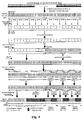
- Fig. 4 is a schematic diagram illustrating the resource mapping process of 10 MHz radio communication system in accordance with an embodiment of the present invention.
- the system bandwidth is 10 MHz
- the number of FFT points is 1024
- the system bandwidth is 20 MHz
- the number of FFT points is 2048
- At least one of the following information is transmitted via a broadcast channel: the number of frequency partitions, the size of individual frequency partitions, fractional frequency reuse factors of individual frequency partitions, the number of sub-bands in each frequency partition, the number of mini-bands in each frequency partition, the number of distributed resource units in each frequency partition and the number of contiguous resource units in each frequency partition.
- the number of frequency partitions can be indicated by the manner of binary bit index. For example, it is represented by a binary value of 2 ⁇ 3 bits, and the practical number of frequency partitions is obtained by adding one to said value, e.g. in the case of 3 bits, 000 represents there is only one frequency partition while 110 represents there are seven frequency partitions. Taking the condition as shown in Fig. 3-Fig. 4 as an example, since there are three frequency partitions in Fig. 3 , the number of frequency partitions can be represented as 010, while since there are four frequency partitions in Fig. 4 , the number of frequency partitions can be represented as 011.
- the size of the frequency partition can be represented by one of sub-band, mini-band and resource unit or the combination thereof, wherein the resource unit is a logical resource unit or a physical resource unit.
- the size of the frequency partition is represented by use of sub-band and/or mini-band.
- Manner 1 the size of the frequency partition are represented by the number of sub-bands, mini-bands or resource units included in the frequency partition, wherein the resource unit is a logical resource unit or a physical resource unit.
- N the number of PRU included by the frequency partition of the base station broadcast system information
- the system information is represented as 00111,00111 and 00111.
- the size of the frequency partition is represented by frequency partition configuration identifier, in which each identifier represents the specific number of sub-bands, mini-bands or resource units included in each frequency partition.
- L FP0 16 PRUs in the frequency partition 0
- L FP1 16 PRUs in the frequency partition 1
- Manner 3 the size of the frequency partition is represented by use of the offset of each frequency partition relative to the first frequency partition.
- 00 represents 16:16:16.
- the representing method of Manner 3 it can be represented as 00000, 01111, 11111, wherein the offset of frequency partition 0 is relative to itself, such that the offset information thereof is 00000, which can be omitted; while the offset of frequency partition 1 relative to frequency partition 0 is 01111, and the offset of frequency partition 2 relative to frequency partition 0 is 11111.
- Manner 4 the size of the frequency partition is represented by use of the number of sub-bands and/or mini-bands included in a frequency partition.
- the size of the frequency partition is represented by the mini-band for the 5MHz bandwidth, using 5 bits, and the number of the included sub-bands is represented by 3 bits. Therefore, frequency partition 0 includes one sub-band and four mini-bands; and the size of frequency partition 0 is 8 mini-bands, which is represented as 01000 wherein the number of the included sub-bands can be represented as 001 by use of 3 bits. Frequency partition 1 includes one sub-band and four mini-bands; and the size of frequency partition 1 is 8 mini-bands, which is represented as 01000 wherein the number of the included sub-band can be represented as 001 by use of 3 bits.
- Frequency partition 2 includes one sub-band and four mini-bands; and the size of frequency partition 2 is 8 mini-bands, which is represented as 01000 wherein the number of the included sub-band can be represented as 001 by use of 3 bits. It should be noted that the bit number representing the sub-band and mini-band should be determined according the system bandwidth to reduce the overhead.
- the number of the distributed resource units or the number of the contiguous resource units can be represented by one of sub-band, mini-band and resource unit or the combination thereof, wherein the resource unit is a logic resource unit or a physical resource unit. Preferably, it is represented by the mini-band.
- Manner 1 the number of the distributed resource unit in the frequency partition is represented by using multiple binary bits to indicate the number of the sub-bands and/or the number of the mini-bands and/or the number of the resource units for distributed resource units in the frequency partition, and the number of the contiguous resource unit in the frequency partition is determined by means of the size of frequency partition and the number of the distributed resource units in the frequency partition (performing subtraction operation).
- the number of the contiguous resource unit in the frequency partition is represented by using multiple binary bits to indicate the number of the sub-bands and/or the number of the mini-bands and/or the number of the resource units for contiguous resource units in the frequency partition; and the number of the distributed resource units in frequency partition is determined by means of the size of frequency partition and the number of the contiguous resource units in frequency partition (performing subtraction operation).
- the multiple binary bits can include 3 ⁇ 7 bits, or the bit number can be determined according to the bandwidth to reduce the overhead, for example, as shown in Table 1: Table 1 Bandwidth (MHz) 5 7 8.75 10 20 Number of FFT Points 512 1024 1024 1024 2048 Bit Number Necessary for Representing Distributed Resource Unit number 3 4 4 4 5 alternatively, as shown in Table 2: Table 2 Bandwidth (MHz) 5 7 8.75 10 20 Number of FFT Points 512 1024 1024 1024 2048 Bit Number Necessary for Representing Distributed Resource Unit number 5 6 6 6 7
- the overhead can be further reduced in combination with the following Manners.
- Manner 3 the configuration mode of using multiple binary bits to indicate the distributed resource unit and the contiguous resource unit. For example, 1 bit is used to indicates whether to map all sub-bands in the frequency partition to contiguous resource units and to map all mini-bands of the frequency partition to distributed resource units, wherein e.g. 1 represents yes while 0 represents no, wherein when the bit is 0, the further indication is given through the number of the distributed resource units as shown in Table 1 or Table 2. Certainly, it can be added to multiple bits for indicating more specific configurations.
- N Sb is the total number of sub-bands
- N Mb is the total number of mini-bands
- L Fpi is the number of the resource units in frequency partition i
- L FPi,Sb is the number of the sub-bands in frequency partition i
- L FPi,Mb is the number of the mini-bands in frequency partition i
- N FPi,CRU is the number of CRUs in frequency partition i
- N FPi,DRU is the number of DRUs in frequency partition i, wherein 0 ⁇ i ⁇ 3.
- the fractional resource mapping information can adopt default settings to further reduce the overhead. For example, in the case of 3 or 4 frequency partitions, the 3 frequency partitions can have the same size in default, and the
- the bit number necessary for representing fractional or all system information can be determined according to the system bandwidth.
- the binary bit number necessary for representing the number of the frequency partitions, the bit number necessary for representing the number of the frequency partitions, the binary bit number necessary for representing the size of the frequency partition, the binary bit number necessary for representing the number of the sub-bands in the frequency partition can all be determined according to the bandwidth, as shown in Table 3: Table 3 Bandwidth (MHz) 5 7 8.75 10 20 Number of FFT points 512 1024 1024 1024 2048 Maximal Number of Frequency Partition 4 4 4 7 Bit Number Necessary for Representing Number of Frequency Partitions 2 2 2 2 3 Bit Number Necessary for Representing Size of Frequency Partition 3 4 4 4 4 4 Bit Number Necessary for Representing Number of Sub-bands in Frequency Partition 3 4 4 4 5
- a terminal can acquire the configuration or division condition of the resource performed by a base station.
- the system information further can include at least one or more of the following: uplink/downlink bandwidth information, multi-carrier information, compatibility system information, control channel information and multicast broadcast information etc., for example.
- the multi-carrier information, compatibility system information, control channel information and multicast broadcast information can be transmitted via secondary broadcast control channel.
- the main broadcast channel is further used for transmitting a super frame serial number, and the system information of the main broadcast channel should be verified by use of 8 or 16 bits CRC.
- the secondary broadcast channel is further used for transmitting a sector ID, and the system information of the secondary broadcast channel should be verified by use of 8 or 16 bits CRC.
- the uplink/downlink bandwidth information includes at least one of the following: the number or proportion of uplink sub-frame and downlink sub-frame in the manner of Time Division Duplex (TDD for short); whether individual carriers belong to the uplink carrier or the downlink carrier in the manner of Frequency Division Duplex (FDD for short), the bandwidth of downlink carrier and/or the bandwidth of uplink carrier in the manner of FDD, the proportion of downlink carrier bandwidth and uplink carrier bandwidth in the manner of FDD.
- TDD Time Division Duplex
- FDD Frequency Division Duplex
- the uplink and the downlink occupy the resource of the same carrier by Time Division Multiplex (TDM for short).
- TDM Time Division Multiplex
- FDM Frequency Division Multiplex
- bit number can be increased for representing more combinations.
- the binary bitmap is used for representing whether each carrier is uplink carrier or downlink carrier. For example, if 3 carrier bandwidths are respectively 5MHz, 5MHz and 10MHz, 101 represents that the first 5MHz carrier and the 10MHz, carrier are both downlink carriers, while the second 5MHz carrier is an uplink carrier.
- the multi-carrier information includes at least one or more of the following: the indication information of whether to support the multi-carrier operation, the duplex modes of each of fractional configuration carriers, the frequency points of each of fractional configuration carriers, the bandwidths of each of fractional configuration carriers, and the usage information of protection sub-carriers under the multi-carrier operation.
- 1 bit is used for representing the indication information of whether to support the multi-carrier operation, wherein 1 represents supporting while 0 represents non-supporting.
- 1-2 bits are used for representing the duplex mode of fractional configuring carriers, wherein 00 represents TDD, 01 represents FDD, 10 represents Half-Frequency Division Duplex (HFDD), and 11 represents that all the fractional configuration carriers adopt the same duplex mode or the duplex mode the same as those of the full configuration carrier corresponding thereto, or 11 is used as Reserved.
- the frequency points, and the bandwidths of fractional configuration carriers and the usage information of protection sub-carriers under the multi-carrier operation can be indicated by the manner of binary bit index or determined by the system bandwidth.
- 000 represents 5MHz
- 001 represents 10MHz
- 010 represents 20MHz
- 011 represents 7MHz
- 100 represents 8.75MHz
- 101 represents that a 10MHz bandwidth is divided into two 5MHz bandwidths
- 110 represents that a 20MHz bandwidth is divided into two 5MHz bandwidths and one 10MHz bandwidth
- 111 represents that a 20MHz bandwidth is divided into two 10MHz bandwidths or represents that a 10MHz or 20MHz bandwidth are not divided into multiple carriers.
- the multi-carrier information indicates the configuration information of full configuration carriers and fractional configuration carriers, and the usage information of protection sub-carrier between carriers including the number of the protection sub-carriers used as the data sub-carriers.
- the multi-carrier information can indicate other carriers' properties including the system bandwidth, frequency point, system configuration information similar to single carrier etc..
- the usage condition of protection sub-carriers can be indicated by transmitting the resource unit number composed of the protection sub-carrier, or indicated by the system bandwidth, for example, when a 20MHz system is divided into two 10MHz systems, the middle protection sub-carrier is extracted to form two physical resource units, i.e.
- the protection sub-carrier at the right of the first 10MHz carrier forms one physical resource unit while the protection sub-carrier at the left of the second 10MHz carrier forms one physical resource unit.
- 1 bit is used for representing whether a carrier is full configuration carrier or fractional configuration carrier, for example, 1 representing the full configuration carrier and 0 representing the fractional configuration carrier.
- the system compatibility information refers to the information transmitted to the previous generation system to support the previous generation system contiguously in the evolution system of the next generation system in the same series of standards, for example, the information which is sent since the IEEE 802.16m system needs to be compatible with the IEEE 802.16e system, wherein the IEEE 802.16 system is a compatible system.
- the system compatibility information includes one or more of the following: the indication information of whether to support a compatible system, the resource location information of compatible system in the downlink, and the resource location information of compatible system in the uplink, wherein the resource location information of compatible system in the downlink includes at least one of the following: the number of sub-frames occupied by the compatible system and the locations of sub-frames occupied by the compatible system; the resource location information of compatible system in the uplink includes at least one of the following: the total number of sub-frames occupied by the compatible system, the number of sub-frames occupied by the compatible system under the TDM mode, the locations of sub-frames occupied by the compatible system under the TDM mode, the locations of sub-frames occupied by the compatible system under the FDM mode, and the proportion of the sub-frames or the number of the resource units occupied by the compatible system under the FDM mode.
- 1 bit can be used for representing whether to support a compatible system wherein 1 represents supporting, and 0 represents non-supporting.
- 1 ⁇ 3 bits are used for representing the location and/or the number of sub-frames occupied by the compatible system in the downlink, wherein for example, 01 is used for representing the downlink frames 0 and 1 are occupied by the compatible system.
- 1 ⁇ 3 bits are used for representing the number of sub-frames occupied by the compatible system in the uplink, wherein for example, 01 is used for representing the first and second sub-frames occupied by the compatible system in the uplink.
- 2 bits are used for indicating the mode of uplink compatible system, i.e. FDM or TDM. For example, 01 represents that it is TDM mode at sub-frame 0 while it is FDM mode at sub-frame 1.
- 3 ⁇ 7 bits are used for representing the bandwidth or, the proportion, the offset or the number of the resource units occupied in the uplink FDM mode.
- the control channel information includes, but is not limited to: the number of streams of the secondary broadcast control channel when using Multiple Input Multiple Output (MIMO for short) mode for transmission, the code rate of secondary broadcast control channel, the location information of unicast service control channel including at least the sub-frame number n in the interval between two unicast service control channels, and the location of the resource occupied by the uplink control channel.
- the location information of resource occupied by the uplink control channel includes: Ranging channel location information, fast feedback channel location information, Hybrid Automatic Repeat Request (HARQ) feedback channel location information, bandwidth request channel location information and location information of Sounding channel.
- MIMO Multiple Input Multiple Output
- 1 or 2 bits can be used for representing the number n of the sub-frames between two unicast service control channels, wherein more particularly, 0 represents 1 sub-frame therebetween while 1 represents 2 sub-frames therebetween.
- 0 represents 1 sub-frame therebetween while 1 represents 2 sub-frames therebetween.
- the resource location of uplink control channel can be indicated by one or the combination of the following: sub-frame label, frequency partition label, the number of logical resource units, logical resource unit label and logical resource unit area identifier.
- the code rate of secondary broadcast control channel is associated with the coding efficiency, the number of replication and the modulation mode of secondary broadcast control channel; and therefore when other factors such as the coding mode and coding efficiency are determined, in the condition that the code rate of broadcast channel is only affected by the times of repetition, the code rate of secondary broadcast control channel is indicated or replaced by the times of repetition.
- the multicast broadcast information includes: the multicast broadcast location information and/or cyclic prefix information used by the multicast broadcast wherein the location information can be indicated by one or the combination of the following: the number of the sub-frames, sub-frame label, frequency partition label, the number of the resource units, resource unit label and resource unit area identification; and the cyclic prefix information indicates the cyclic prefix length used in the multicast broadcast area through binary bit index.
- the logical resource units 000 ⁇ 111 of sub-frame 2 are defined as multicast broadcast area; and alternatively, the frequency partition 3 in sub-frame 3 is multicast broadcast area or the multicast broadcast area is indicated by resource area defined by the logical resource serial number and sub-frame serial number.
- the CP length used in the multicast broadcast area can be indicated by one of the following methods: it is indicated by 1 bit whether to use a long CP or a short CP, or it is indicated, by 2 bits, which CP length (for example 1/4, 1/8, 1/16 and the like), is used, or it is obtained by the terminal detection.
- the resource allocation information are needed besides of the system information.
- the resource allocation information includes the location indication information of radio resource, with the indication information including at least one of the following: sub-frame label, logical resource unit serial number, offset respective to the determined resource location and logical resource area identifier etc.
- the starting location of resource allocation is a determined location, and the length relative to the starting location is an offset.
- the terminal can determine the broadcast control channel location according to the system bandwidth information and the multi-carrier information, decode the broadcast control channel and the channel bearing the resource allocation information, acquire, from the broadcast control channel, other system information including the resource mapping information, and acquire the resource allocation information from the channel bearing the resource allocation information.
- the logical resource indicated by the radio resource location indication information of the resource allocation information is mapped to the physical resource through an inverse resource mapping process (also called reverse mapping) according to the resource mapping information. For example, as show in Fig.
- the terminal first decodes the main broadcast control channel of the broadcast control channel, then decodes the secondary broadcast control channel to acquire the resource mapping information, afterwards decodes the unicast service control channel, and then decodes the resource allocation information, so as to acquire the physical resource location for receiving/transmitting data.
- the resource mapping information by configuring the resource mapping information, it is possible for a terminal to acquire the resource configuration, mapping and/or division condition performed by the base station, and to determine the location for the terminal receiving/transmitting resource in combination with the resource mapping information, thereby improving the efficiency of scheduling radio resource and reducing the system overhead.
Applications Claiming Priority (2)
| Application Number | Priority Date | Filing Date | Title |
|---|---|---|---|
| CN200910001749.7A CN101772170A (zh) | 2009-01-04 | 2009-01-04 | 通信系统中的系统信息管理及传输方法 |
| PCT/CN2009/074017 WO2010075704A1 (zh) | 2009-01-04 | 2009-09-17 | 系统信息传输方法 |
Publications (3)
| Publication Number | Publication Date |
|---|---|
| EP2384041A1 EP2384041A1 (en) | 2011-11-02 |
| EP2384041A4 EP2384041A4 (en) | 2014-04-23 |
| EP2384041B1 true EP2384041B1 (en) | 2016-03-16 |
Family
ID=42309785
Family Applications (1)
| Application Number | Title | Priority Date | Filing Date |
|---|---|---|---|
| EP09835991.2A Active EP2384041B1 (en) | 2009-01-04 | 2009-09-17 | System information transmission method |
Country Status (5)
| Country | Link |
|---|---|
| US (1) | US20110267996A1 (zh) |
| EP (1) | EP2384041B1 (zh) |
| KR (1) | KR101585086B1 (zh) |
| CN (1) | CN101772170A (zh) |
| WO (1) | WO2010075704A1 (zh) |
Families Citing this family (20)
| Publication number | Priority date | Publication date | Assignee | Title |
|---|---|---|---|---|
| CN101925184B (zh) | 2009-06-11 | 2015-07-22 | 中兴通讯股份有限公司 | 广播控制信道的资源映射方法 |
| US8730827B2 (en) * | 2010-03-05 | 2014-05-20 | Intel Corporation | Estimating quality of a signal in mobile wireless communication systems |
| US20120026954A1 (en) * | 2010-07-09 | 2012-02-02 | Interdigital Patent Holdings, Inc. | Resource allocation signaling of wireless communication networks |
| EP2693799B1 (en) * | 2011-07-13 | 2016-12-07 | Sun Patent Trust | Terminal apparatus and transmission method |
| US10111104B2 (en) * | 2012-12-26 | 2018-10-23 | Lg Electonics Inc. | Method for measuring subband in wireless communication system, and apparatus therefor |
| WO2015042916A1 (zh) * | 2013-09-29 | 2015-04-02 | 华为技术有限公司 | 一种发送信息的方法、及确定cp类型的方法 |
| US10135652B2 (en) | 2013-10-24 | 2018-11-20 | Futurewei Technologies, Inc. | System and method for setting cyclic prefix length |
| WO2016005002A1 (en) * | 2014-07-11 | 2016-01-14 | Nokia Solutions And Networks Oy | Methods and apparatuses for bearer type signalling |
| US10749724B2 (en) | 2014-11-20 | 2020-08-18 | Futurewei Technologies, Inc. | System and method for setting cyclic prefix length |
| US20160192390A1 (en) * | 2014-12-30 | 2016-06-30 | Electronics And Telecommunications Research Institute | Method for transmitting data based on limited contention |
| CN111654914B (zh) * | 2015-09-08 | 2023-02-14 | 华为技术有限公司 | 用于上行数据传输的方法、网络设备和终端设备 |
| US10575210B2 (en) * | 2015-10-30 | 2020-02-25 | Qualcomm Incorporated | Cyclic redundancy check length management |
| KR102178412B1 (ko) * | 2016-07-15 | 2020-11-16 | 주식회사 케이티 | 새로운 무선 액세스 망에서 단말을 위한 동기화 신호 및 시스템 정보를 송수신하는 방법 및 장치 |
| JP7170643B2 (ja) | 2016-12-23 | 2022-11-14 | オッポ広東移動通信有限公司 | データ伝送方法、ネットワーク装置と端末装置 |
| CN108633055B (zh) * | 2017-03-24 | 2022-02-25 | 华为技术有限公司 | 一种信息传输方法及通信设备 |
| GB2563454A (en) * | 2017-06-16 | 2018-12-19 | Nec Corp | Communication system |
| CN109392139B (zh) * | 2017-08-11 | 2020-04-14 | 维沃移动通信有限公司 | 一种接收广播消息的资源位置指示方法、装置及系统 |
| JP7064566B2 (ja) * | 2017-09-14 | 2022-05-10 | オッポ広東移動通信有限公司 | 時間領域リソース確定方法、装置、記憶媒体及びシステム |
| CN113163419B (zh) * | 2021-02-22 | 2022-07-22 | 国网山东省电力公司平邑县供电公司 | 一种电力系统高速率覆盖网络的资源调度系统 |
| CN115801888A (zh) * | 2022-11-16 | 2023-03-14 | 云南电网有限责任公司 | 一种基于通信技术的安全无线通信系统 |
Family Cites Families (9)
| Publication number | Priority date | Publication date | Assignee | Title |
|---|---|---|---|---|
| CN100359982C (zh) * | 2004-10-20 | 2008-01-02 | 中兴通讯股份有限公司 | 多载频小区系统中共享信道的配置及使用方法 |
| CN100479548C (zh) * | 2006-06-21 | 2009-04-15 | 华为技术有限公司 | 一种传送系统消息的方法及装置 |
| CN101123805A (zh) * | 2006-08-11 | 2008-02-13 | 华为技术有限公司 | 正交频分复用接入系统及其设备、传输方法和终端 |
| US8400998B2 (en) * | 2006-08-23 | 2013-03-19 | Motorola Mobility Llc | Downlink control channel signaling in wireless communication systems |
| US20080057972A1 (en) * | 2006-09-05 | 2008-03-06 | Nokia Siemens Network Gmbh & Co., Kg | Method for allocating resources in a radio communication system |
| KR100943619B1 (ko) * | 2006-10-02 | 2010-02-24 | 삼성전자주식회사 | 확장성 대역폭을 지원하는 셀룰러 무선통신시스템을 위한 하향링크 동기채널의 송수신 방법 및 장치 |
| CN100499630C (zh) * | 2006-10-20 | 2009-06-10 | 北京泰美世纪科技有限公司 | 一种多载波数字移动多媒体广播的数字信息传输方法 |
| CN101536406B (zh) * | 2006-10-31 | 2014-12-24 | 艾利森电话股份有限公司 | 电信系统中的方法和设备 |
| US8204020B2 (en) * | 2008-10-22 | 2012-06-19 | Lg Electronics Inc. | Method and apparatus for mapping resource unit in wireless communication system |
-
2009
- 2009-01-04 CN CN200910001749.7A patent/CN101772170A/zh active Pending
- 2009-09-17 US US13/143,179 patent/US20110267996A1/en not_active Abandoned
- 2009-09-17 EP EP09835991.2A patent/EP2384041B1/en active Active
- 2009-09-17 WO PCT/CN2009/074017 patent/WO2010075704A1/zh active Application Filing
- 2009-09-17 KR KR1020117009981A patent/KR101585086B1/ko not_active IP Right Cessation
Also Published As
| Publication number | Publication date |
|---|---|
| KR101585086B1 (ko) | 2016-01-13 |
| US20110267996A1 (en) | 2011-11-03 |
| WO2010075704A1 (zh) | 2010-07-08 |
| EP2384041A1 (en) | 2011-11-02 |
| KR20110102876A (ko) | 2011-09-19 |
| EP2384041A4 (en) | 2014-04-23 |
| CN101772170A (zh) | 2010-07-07 |
Similar Documents
| Publication | Publication Date | Title |
|---|---|---|
| EP2384041B1 (en) | System information transmission method | |
| US10999833B2 (en) | Electronic device and method for transmitting PDCCH and PDSCH, and a method performed by an electronic device for communicating data using a plurality of sub-carriers | |
| US11129153B2 (en) | Telecommunications systems and methods for machine type communication | |
| US8848682B2 (en) | Method for sub-channelization and resource mapping of wireless resources | |
| EP2373106B1 (en) | Resource mapping methods for control channels | |
| US8861528B2 (en) | Apparatus and method for resource selection in OFDMA systems | |
| KR20110083519A (ko) | 무선 통신 시스템에서 향상된 멀티캐스트 브로드캐스트 서비스 데이터를 위한 자원 할당 방법 및 장치 | |
| US8355374B2 (en) | Method for signaling uplink system configuration information |
Legal Events
| Date | Code | Title | Description |
|---|---|---|---|
| PUAI | Public reference made under article 153(3) epc to a published international application that has entered the european phase |
Free format text: ORIGINAL CODE: 0009012 |
|
| 17P | Request for examination filed |
Effective date: 20110729 |
|
| AK | Designated contracting states |
Kind code of ref document: A1 Designated state(s): AT BE BG CH CY CZ DE DK EE ES FI FR GB GR HR HU IE IS IT LI LT LU LV MC MK MT NL NO PL PT RO SE SI SK SM TR |
|
| DAX | Request for extension of the european patent (deleted) | ||
| REG | Reference to a national code |
Ref country code: DE Ref legal event code: R079 Ref document number: 602009036890 Country of ref document: DE Free format text: PREVIOUS MAIN CLASS: H04W0016000000 Ipc: H04W0072040000 |
|
| A4 | Supplementary search report drawn up and despatched |
Effective date: 20140324 |
|
| RIC1 | Information provided on ipc code assigned before grant |
Ipc: H04W 72/04 20090101AFI20140318BHEP |
|
| 17Q | First examination report despatched |
Effective date: 20150122 |
|
| GRAP | Despatch of communication of intention to grant a patent |
Free format text: ORIGINAL CODE: EPIDOSNIGR1 |
|
| INTG | Intention to grant announced |
Effective date: 20150826 |
|
| GRAS | Grant fee paid |
Free format text: ORIGINAL CODE: EPIDOSNIGR3 |
|
| GRAA | (expected) grant |
Free format text: ORIGINAL CODE: 0009210 |
|
| AK | Designated contracting states |
Kind code of ref document: B1 Designated state(s): AT BE BG CH CY CZ DE DK EE ES FI FR GB GR HR HU IE IS IT LI LT LU LV MC MK MT NL NO PL PT RO SE SI SK SM TR |
|
| REG | Reference to a national code |
Ref country code: GB Ref legal event code: FG4D |
|
| REG | Reference to a national code |
Ref country code: CH Ref legal event code: EP |
|
| REG | Reference to a national code |
Ref country code: IE Ref legal event code: FG4D |
|
| REG | Reference to a national code |
Ref country code: AT Ref legal event code: REF Ref document number: 782137 Country of ref document: AT Kind code of ref document: T Effective date: 20160415 |
|
| REG | Reference to a national code |
Ref country code: DE Ref legal event code: R096 Ref document number: 602009036890 Country of ref document: DE |
|
| REG | Reference to a national code |
Ref country code: NL Ref legal event code: MP Effective date: 20160316 |
|
| REG | Reference to a national code |
Ref country code: LT Ref legal event code: MG4D |
|
| PG25 | Lapsed in a contracting state [announced via postgrant information from national office to epo] |
Ref country code: NO Free format text: LAPSE BECAUSE OF FAILURE TO SUBMIT A TRANSLATION OF THE DESCRIPTION OR TO PAY THE FEE WITHIN THE PRESCRIBED TIME-LIMIT Effective date: 20160616 Ref country code: FI Free format text: LAPSE BECAUSE OF FAILURE TO SUBMIT A TRANSLATION OF THE DESCRIPTION OR TO PAY THE FEE WITHIN THE PRESCRIBED TIME-LIMIT Effective date: 20160316 Ref country code: HR Free format text: LAPSE BECAUSE OF FAILURE TO SUBMIT A TRANSLATION OF THE DESCRIPTION OR TO PAY THE FEE WITHIN THE PRESCRIBED TIME-LIMIT Effective date: 20160316 Ref country code: GR Free format text: LAPSE BECAUSE OF FAILURE TO SUBMIT A TRANSLATION OF THE DESCRIPTION OR TO PAY THE FEE WITHIN THE PRESCRIBED TIME-LIMIT Effective date: 20160617 |
|
| REG | Reference to a national code |
Ref country code: AT Ref legal event code: MK05 Ref document number: 782137 Country of ref document: AT Kind code of ref document: T Effective date: 20160316 |
|
| PG25 | Lapsed in a contracting state [announced via postgrant information from national office to epo] |
Ref country code: NL Free format text: LAPSE BECAUSE OF FAILURE TO SUBMIT A TRANSLATION OF THE DESCRIPTION OR TO PAY THE FEE WITHIN THE PRESCRIBED TIME-LIMIT Effective date: 20160316 Ref country code: LT Free format text: LAPSE BECAUSE OF FAILURE TO SUBMIT A TRANSLATION OF THE DESCRIPTION OR TO PAY THE FEE WITHIN THE PRESCRIBED TIME-LIMIT Effective date: 20160316 Ref country code: SE Free format text: LAPSE BECAUSE OF FAILURE TO SUBMIT A TRANSLATION OF THE DESCRIPTION OR TO PAY THE FEE WITHIN THE PRESCRIBED TIME-LIMIT Effective date: 20160316 Ref country code: LV Free format text: LAPSE BECAUSE OF FAILURE TO SUBMIT A TRANSLATION OF THE DESCRIPTION OR TO PAY THE FEE WITHIN THE PRESCRIBED TIME-LIMIT Effective date: 20160316 |
|
| PG25 | Lapsed in a contracting state [announced via postgrant information from national office to epo] |
Ref country code: EE Free format text: LAPSE BECAUSE OF FAILURE TO SUBMIT A TRANSLATION OF THE DESCRIPTION OR TO PAY THE FEE WITHIN THE PRESCRIBED TIME-LIMIT Effective date: 20160316 Ref country code: IS Free format text: LAPSE BECAUSE OF FAILURE TO SUBMIT A TRANSLATION OF THE DESCRIPTION OR TO PAY THE FEE WITHIN THE PRESCRIBED TIME-LIMIT Effective date: 20160716 Ref country code: PL Free format text: LAPSE BECAUSE OF FAILURE TO SUBMIT A TRANSLATION OF THE DESCRIPTION OR TO PAY THE FEE WITHIN THE PRESCRIBED TIME-LIMIT Effective date: 20160316 |
|
| PG25 | Lapsed in a contracting state [announced via postgrant information from national office to epo] |
Ref country code: SM Free format text: LAPSE BECAUSE OF FAILURE TO SUBMIT A TRANSLATION OF THE DESCRIPTION OR TO PAY THE FEE WITHIN THE PRESCRIBED TIME-LIMIT Effective date: 20160316 Ref country code: PT Free format text: LAPSE BECAUSE OF FAILURE TO SUBMIT A TRANSLATION OF THE DESCRIPTION OR TO PAY THE FEE WITHIN THE PRESCRIBED TIME-LIMIT Effective date: 20160718 Ref country code: ES Free format text: LAPSE BECAUSE OF FAILURE TO SUBMIT A TRANSLATION OF THE DESCRIPTION OR TO PAY THE FEE WITHIN THE PRESCRIBED TIME-LIMIT Effective date: 20160316 Ref country code: AT Free format text: LAPSE BECAUSE OF FAILURE TO SUBMIT A TRANSLATION OF THE DESCRIPTION OR TO PAY THE FEE WITHIN THE PRESCRIBED TIME-LIMIT Effective date: 20160316 Ref country code: SK Free format text: LAPSE BECAUSE OF FAILURE TO SUBMIT A TRANSLATION OF THE DESCRIPTION OR TO PAY THE FEE WITHIN THE PRESCRIBED TIME-LIMIT Effective date: 20160316 Ref country code: RO Free format text: LAPSE BECAUSE OF FAILURE TO SUBMIT A TRANSLATION OF THE DESCRIPTION OR TO PAY THE FEE WITHIN THE PRESCRIBED TIME-LIMIT Effective date: 20160316 Ref country code: CZ Free format text: LAPSE BECAUSE OF FAILURE TO SUBMIT A TRANSLATION OF THE DESCRIPTION OR TO PAY THE FEE WITHIN THE PRESCRIBED TIME-LIMIT Effective date: 20160316 |
|
| REG | Reference to a national code |
Ref country code: DE Ref legal event code: R097 Ref document number: 602009036890 Country of ref document: DE |
|
| PG25 | Lapsed in a contracting state [announced via postgrant information from national office to epo] |
Ref country code: IT Free format text: LAPSE BECAUSE OF FAILURE TO SUBMIT A TRANSLATION OF THE DESCRIPTION OR TO PAY THE FEE WITHIN THE PRESCRIBED TIME-LIMIT Effective date: 20160316 Ref country code: BE Free format text: LAPSE BECAUSE OF FAILURE TO SUBMIT A TRANSLATION OF THE DESCRIPTION OR TO PAY THE FEE WITHIN THE PRESCRIBED TIME-LIMIT Effective date: 20160316 |
|
| PLBE | No opposition filed within time limit |
Free format text: ORIGINAL CODE: 0009261 |
|
| STAA | Information on the status of an ep patent application or granted ep patent |
Free format text: STATUS: NO OPPOSITION FILED WITHIN TIME LIMIT |
|
| PG25 | Lapsed in a contracting state [announced via postgrant information from national office to epo] |
Ref country code: DK Free format text: LAPSE BECAUSE OF FAILURE TO SUBMIT A TRANSLATION OF THE DESCRIPTION OR TO PAY THE FEE WITHIN THE PRESCRIBED TIME-LIMIT Effective date: 20160316 |
|
| 26N | No opposition filed |
Effective date: 20161219 |
|
| PG25 | Lapsed in a contracting state [announced via postgrant information from national office to epo] |
Ref country code: BG Free format text: LAPSE BECAUSE OF FAILURE TO SUBMIT A TRANSLATION OF THE DESCRIPTION OR TO PAY THE FEE WITHIN THE PRESCRIBED TIME-LIMIT Effective date: 20160616 |
|
| PG25 | Lapsed in a contracting state [announced via postgrant information from national office to epo] |
Ref country code: MC Free format text: LAPSE BECAUSE OF FAILURE TO SUBMIT A TRANSLATION OF THE DESCRIPTION OR TO PAY THE FEE WITHIN THE PRESCRIBED TIME-LIMIT Effective date: 20160316 |
|
| REG | Reference to a national code |
Ref country code: CH Ref legal event code: PL |
|
| PG25 | Lapsed in a contracting state [announced via postgrant information from national office to epo] |
Ref country code: SI Free format text: LAPSE BECAUSE OF FAILURE TO SUBMIT A TRANSLATION OF THE DESCRIPTION OR TO PAY THE FEE WITHIN THE PRESCRIBED TIME-LIMIT Effective date: 20160316 |
|
| REG | Reference to a national code |
Ref country code: IE Ref legal event code: MM4A |
|
| REG | Reference to a national code |
Ref country code: FR Ref legal event code: ST Effective date: 20170531 |
|
| PG25 | Lapsed in a contracting state [announced via postgrant information from national office to epo] |
Ref country code: CH Free format text: LAPSE BECAUSE OF NON-PAYMENT OF DUE FEES Effective date: 20160930 Ref country code: IE Free format text: LAPSE BECAUSE OF NON-PAYMENT OF DUE FEES Effective date: 20160917 Ref country code: FR Free format text: LAPSE BECAUSE OF NON-PAYMENT OF DUE FEES Effective date: 20160930 Ref country code: LI Free format text: LAPSE BECAUSE OF NON-PAYMENT OF DUE FEES Effective date: 20160930 |
|
| PG25 | Lapsed in a contracting state [announced via postgrant information from national office to epo] |
Ref country code: LU Free format text: LAPSE BECAUSE OF NON-PAYMENT OF DUE FEES Effective date: 20160917 |
|
| PG25 | Lapsed in a contracting state [announced via postgrant information from national office to epo] |
Ref country code: CY Free format text: LAPSE BECAUSE OF FAILURE TO SUBMIT A TRANSLATION OF THE DESCRIPTION OR TO PAY THE FEE WITHIN THE PRESCRIBED TIME-LIMIT Effective date: 20160316 Ref country code: HU Free format text: LAPSE BECAUSE OF FAILURE TO SUBMIT A TRANSLATION OF THE DESCRIPTION OR TO PAY THE FEE WITHIN THE PRESCRIBED TIME-LIMIT; INVALID AB INITIO Effective date: 20090917 |
|
| PG25 | Lapsed in a contracting state [announced via postgrant information from national office to epo] |
Ref country code: MK Free format text: LAPSE BECAUSE OF FAILURE TO SUBMIT A TRANSLATION OF THE DESCRIPTION OR TO PAY THE FEE WITHIN THE PRESCRIBED TIME-LIMIT Effective date: 20160316 Ref country code: TR Free format text: LAPSE BECAUSE OF FAILURE TO SUBMIT A TRANSLATION OF THE DESCRIPTION OR TO PAY THE FEE WITHIN THE PRESCRIBED TIME-LIMIT Effective date: 20160316 Ref country code: MT Free format text: LAPSE BECAUSE OF NON-PAYMENT OF DUE FEES Effective date: 20160930 |
|
| P01 | Opt-out of the competence of the unified patent court (upc) registered |
Effective date: 20230530 |
|
| PGFP | Annual fee paid to national office [announced via postgrant information from national office to epo] |
Ref country code: GB Payment date: 20230727 Year of fee payment: 15 |
|
| PGFP | Annual fee paid to national office [announced via postgrant information from national office to epo] |
Ref country code: DE Payment date: 20230726 Year of fee payment: 15 |