EP2383979B1 - Camera platform system and imaging system - Google Patents
Camera platform system and imaging system Download PDFInfo
- Publication number
- EP2383979B1 EP2383979B1 EP11164041.3A EP11164041A EP2383979B1 EP 2383979 B1 EP2383979 B1 EP 2383979B1 EP 11164041 A EP11164041 A EP 11164041A EP 2383979 B1 EP2383979 B1 EP 2383979B1
- Authority
- EP
- European Patent Office
- Prior art keywords
- lens
- position information
- motion prediction
- image
- camera platform
- Prior art date
- Legal status (The legal status is an assumption and is not a legal conclusion. Google has not performed a legal analysis and makes no representation as to the accuracy of the status listed.)
- Active
Links
Images


Classifications
-
- H—ELECTRICITY
- H04—ELECTRIC COMMUNICATION TECHNIQUE
- H04N—PICTORIAL COMMUNICATION, e.g. TELEVISION
- H04N5/00—Details of television systems
- H04N5/222—Studio circuitry; Studio devices; Studio equipment
-
- G—PHYSICS
- G03—PHOTOGRAPHY; CINEMATOGRAPHY; ANALOGOUS TECHNIQUES USING WAVES OTHER THAN OPTICAL WAVES; ELECTROGRAPHY; HOLOGRAPHY
- G03B—APPARATUS OR ARRANGEMENTS FOR TAKING PHOTOGRAPHS OR FOR PROJECTING OR VIEWING THEM; APPARATUS OR ARRANGEMENTS EMPLOYING ANALOGOUS TECHNIQUES USING WAVES OTHER THAN OPTICAL WAVES; ACCESSORIES THEREFOR
- G03B13/00—Viewfinders; Focusing aids for cameras; Means for focusing for cameras; Autofocus systems for cameras
- G03B13/32—Means for focusing
- G03B13/34—Power focusing
- G03B13/36—Autofocus systems
-
- G—PHYSICS
- G03—PHOTOGRAPHY; CINEMATOGRAPHY; ANALOGOUS TECHNIQUES USING WAVES OTHER THAN OPTICAL WAVES; ELECTROGRAPHY; HOLOGRAPHY
- G03B—APPARATUS OR ARRANGEMENTS FOR TAKING PHOTOGRAPHS OR FOR PROJECTING OR VIEWING THEM; APPARATUS OR ARRANGEMENTS EMPLOYING ANALOGOUS TECHNIQUES USING WAVES OTHER THAN OPTICAL WAVES; ACCESSORIES THEREFOR
- G03B3/00—Focusing arrangements of general interest for cameras, projectors or printers
- G03B3/10—Power-operated focusing
- G03B3/12—Power-operated focusing adapted for remote control
-
- H—ELECTRICITY
- H04—ELECTRIC COMMUNICATION TECHNIQUE
- H04N—PICTORIAL COMMUNICATION, e.g. TELEVISION
- H04N23/00—Cameras or camera modules comprising electronic image sensors; Control thereof
- H04N23/60—Control of cameras or camera modules
- H04N23/695—Control of camera direction for changing a field of view, e.g. pan, tilt or based on tracking of objects
Landscapes
- Physics & Mathematics (AREA)
- General Physics & Mathematics (AREA)
- Engineering & Computer Science (AREA)
- Multimedia (AREA)
- Signal Processing (AREA)
- Studio Devices (AREA)
- Accessories Of Cameras (AREA)
Description
- The present invention relates to an imaging system, and in particular, relates to a camera platform system that can remotely drive a zoom/focus/tilt/pan and the like.
- Conventionally, an imaging system (virtual studio system) for acquiring a composite image in which a photographed image is synthesized with a computer graphic (hereinafter referred to as "CG") image is well known. In the virtual studio system, a CG image, which is the background (or foreground) of a photographed image, needs to be changed in accordance with the motion of the photographed image. A camera serving as an imaging apparatus for obtaining a photographed image is mounted on a remote control camera platform that remotely controls panning for rotating the direction of the camera in the left and right direction, or tilting for rotating the direction of the camera in the up-and-down direction (pan/tilt), and zoom/focus of a lens. Furthermore, a camera platform system constituted by a camera, a lens, and a remote control camera platform together with an operation device for remotely controlling these components and an image synthesizing system for synthesizing a photographed image with a CG image form a virtual studio system. Separately from pan/tilt position information about the camera and zoom/focus position information about the lens, a photographed image captured by a camera is transmitted from the camera platform system to the image synthesizing system. The image synthesizing system generates a composite image in which a CG image (signal) is changed in accordance with the timing of the transmitted photographed image (signal), based on the photographed image (signal) transmitted from the camera platform system and information about the positions of the camera and the lens.
- In this context, as a device for synchronizing the timing between a photographed image (signal) and a CG image (signal), Japanese Patent No.
3478740 11-112856 - However, in the imaging system employing an encoder, the encoder is disposed on the side of the lens device, a position detection mechanism such as an encoding counter or the like needs to be provided separately on the side of the image forming system, resulting in an increase in the size and the production cost of the apparatus. Also, when the imaging system is applied as a camera platform system, a lens to be mounted needs to have a position detection mechanism, and thus, the model of a lens that can be mounted in a remote control camera platform is limited.
- On the other hand, in the apparatus that takes into account the delay factor of the drive units of the remote control camera platform, such an apparatus would be greatly affected by transmission delay when a long distance between the operation device and the remote control camera platform exists in the case of, for example, golf broadcast or when the apparatus is adopted into a system that is connected thereto via other equipment. In particular, in the case of establishing a connection using a public line where delay time is not constant, a change in delay time may greatly affect on the accuracy of a position signal. Furthermore, in a system in which a connection is established by switching an operation device and a plurality of remote control camera platforms such as in a sport (golf, baseball, etc.) broadcast or the like, the operation device needs to recognize information about the delay amount of all of the remote control camera platforms, resulting in a more complex configuration.
- As described above, in an imaging system employing a conventional remote control camera platform, an expensive machine and a complex transmission path need to be constructed in order to synchronize a photographed image and a CG image, whereby the construction of an imaging system is necessitated depending on a desired utilization, resulting in a poor general applicability.
-
US 2010/026821 A1 discloses an optical apparatus which includes an image pickup optical system including a focus lens, a controller controlling movement of the focus lens in an optical axis direction of the image pickup optical system, a shake detector detecting a shake amount of the optical apparatus in the optical axis direction, and a memory storing plural shake amounts sequentially detected by the shake detector. The controller calculates, in response to a start instruction of exposure for the image pickup and before start of the exposure, a predictive value of the shake amount for a time point of the exposure based on the plural shake amounts stored in the memory and including at least one shake amount detected after the start instruction of exposure. The controller moves the focus lens to a position corresponding to the predictive value before the start of the exposure. -
US 6,311,019 B1 discloses an automatic focus adjusting apparatus including an image move-amount detecting section, an image position predicting section and a control section. The image move-amount detecting section detects, for each of a pair of images of a subject divided in a predetermined direction, image positions of the subject in an image-divided direction and in a direction approximately orthogonal with this image-divided direction respectively on photoelectric conversion elements at mutually different first and second times respectively, and obtains move amounts of the images of the subject in the image-divided direction based on a result of this detection. The image position predicting section predicts an image position of the subject in an image-divided direction at a third time different from the first and second times, based on an output from the image move-amount detecting section. The control section carries out a focus adjustment so that the image of the subject is in focus at the third time, based on an output from the image position predicting section. - Accordingly, the present invention provides a remote control camera platform that has a simple structure without requiring a separate expensive position detection mechanism, is not readily affected by signal delay due to a transmission path between an operation device and the remote control camera platform, and is capable of outputting more accurate position information.
- The present invention in its aspect provides a camera platform system as specified in
claims 1 to 6. And the present invention in its aspect provides an imaging system as specified inclaims - According to the present invention, a remote control camera platform that has a simple structure that does not require a separate expensive position detection mechanism, is not readily affected by signal delay due to a transmission path between an operation device and the remote control camera platform, and is capable of outputting more accurate position information may be provided.
- Further features of the present invention will become apparent from the following description of exemplary embodiments with reference to the attached drawings.
-
-
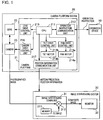
FIG. 1 is a block diagram illustrating the configuration of an imaging system according to a first embodiment of the present invention. -
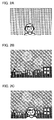
FIG. 2A is an explanatory diagram illustrating an example of an image, in particular, a photographed image obtained by the imaging system of the present invention. -
FIG. 2B is an explanatory diagram illustrating an example of an image, in particular, a CG image obtained by the imaging system of the present invention. -
FIG. 2C is an explanatory diagram illustrating an example of an image, in particular, a composite image obtained by the imaging system of the present invention. -
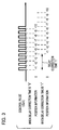
FIG. 3 is an explanatory diagram illustrating a method for updating position information performed by the imaging system of the present invention. -
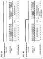
FIG. 4A is an explanatory diagram illustrating a method for updating position information performed by the imaging system of the present invention, and in particular illustrating a method for updating position information with respect to the control of a pan motor when the pan motor is operated in the same direction. -
FIG. 4B is an explanatory diagram illustrating a method for updating position information performed by the imaging system of the present invention, and in particular illustrating a method for updating position information subjected to a backlash correction with respect to the control of a pan motor when the pan motor is operated in the reverse direction. -
FIG. 5 is a block diagram illustrating the configuration of an imaging system according to a second embodiment. -
FIG. 6 is a flowchart illustrating the flow of processing executed by a CPU according to the second embodiment. -
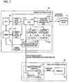
FIG. 7 is a block diagram illustrating the configuration of an imaging system according to a third embodiment of the present invention. -
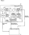
FIG. 8 is a block diagram illustrating the configuration of an imaging system according to a fourth embodiment of the present invention. -
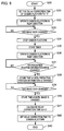
FIG. 9 is a flowchart illustrating the flow of processing executed by a parameter setting computer. -
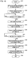
FIG. 10 is a flowchart illustrating the flow of processing executed by a parameter setting computer. -
FIG. 11 is a block diagram illustrating the configuration of an imaging system according to a fifth embodiment. -
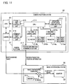
FIG. 12 is a schematic diagram illustrating the configuration of a pan origin detection mechanism according to the fifth embodiment. -
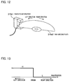
FIG. 13 is an explanatory diagram illustrating an output waveform of a photo-interrupter according to the fifth embodiment. -
FIG. 14 is a flowchart illustrating the flow of processing executed by a CPU according to the fifth embodiment. - Hereinafter, preferred embodiments of the present invention will now be described with reference to the accompanying drawings.
- First, the configuration of an imaging system according to a first embodiment of the present invention will be described with reference to
FIG. 1. FIG. 1 is a block diagram illustrating the configuration of an imaging system according to a first embodiment of the present invention. InFIG. 1 , the imaging system of the present embodiment is constituted by anoperation device 10, acamera platform system 20, and an image synthesizingsystem 30. An operator operates theoperation device 10, and remotely operates thecamera platform system 20 to thereby adjust zoom/focus/tilt/pan and various functions of a camera, whereby a desired image can be acquired. A photographed image acquired by thecamera platform system 20 is synthesized with a CG image using theimage synthesizing system 30. - The
camera platform system 20 is constituted by acamera platform 21, alens 22, and acamera 23. Thecamera platform 21 is constituted by aCPU 211, an operationinstruction communication unit 212, a pandrive control unit 213a, a tiltdrive control unit 213b, apan motor 214a, atilt motor 214b, a lensdrive control unit 215, a cameradrive control unit 216, and a positioninformation communication unit 217. TheCPU 211 receives an operation instruction given by theoperation device 10 via the operationinstruction communication unit 212. When the received operation instruction is a pan/tilt operation instruction, the operation instruction is converted into a drive control signal, and the drive control signal is output to the pandrive control unit 213a and the tiltdrive control unit 213b to thereby operate thepan motor 214a and thetilt motor 214b. When the received operation instruction is a zoom/focus operation instruction, the operation instruction is converted into a drive control signal to thereby perform control of zoom/focus of thelens 22. When an operation instruction for thecamera 23 is made, the operation instruction is converted into a drive control signal to thereby control thecamera 23. Also, theCPU 211 outputs motion prediction position information regarding the motion prediction position, that is, the current position of a zoom/focus/tilt/pan/iris or the like (an object to be driven) to the positioninformation communication unit 217 at a certain time interval. Hence, theCPU 211 functions as a motion prediction position calculation unit configured to convert the operation instruction output from theoperation device 10 into a drive control signal corresponding to the operation of a zoom/focus/tilt/pan/iris and output the drive control signal to thedrive control units CPU 211 functions as a motion prediction position output unit configured to output the motion prediction position of a zoom/focus/tilt/pan/iris based on the converted drive control signal. Furthermore, the positioninformation communication unit 217 functions as a motion prediction position output unit configured to transmit the motion prediction position information to theimage synthesizing system 30. Note that a program that controls the entirecamera platform system 20 is stored in a storage unit (not shown) such as a hard disk or the like. The storage unit is also employed as a storage unit configured to store parameters for correcting a delay time from the conversion of the aforementioned drive control signal to the calculation of the motion prediction position. Furthermore, the storage unit is also employed as a storage unit configured to store parameters for correcting backlash (a time lag or a positional shift caused thereby) when a zoom/focus/tilt/pan is operated. While theCPU 211 calculates the motion prediction position (the integrated value of command values) as the current position at a certain time interval, theCPU 211 may also calculate the current and future motion prediction positions at a certain time interval when a position command (a command signal for specifying the target position) is made from theoperation device 10. - The
image synthesizing system 30 is constituted by animage synthesizing computer 31 and amonitor 32. A general purpose personal computer (PC) or the like is employed for theimage synthesizing computer 31. Also, theimage synthesizing computer 31 operates based on a program that is stored on a hard disk (not shown) or the like and carries out control relating to at least image synthesis in the imaging system of the present invention. A CG image, which has been generated by theimage synthesizing computer 31 or other PC using an operation unit (not shown) such as a known keyboard/mouse, or the like is stored in astorage area 311 such as a hard disk, a memory, or the like. Furthermore, the CG image stored in thestorage area 311 is output to amixing circuit 312 by the operation instructions output from theoperation device 10. Note that a program that controls the overall imaging system including theoperation device 10 and thecamera platform system 20 may be stored in theimage synthesizing system 30. - With this arrangement, the
image synthesizing computer 31 generates a composite image by synthesizing a photographed image captured by thecamera 23 with a CG image stored in amemory 311 using themixing circuit 312 based on the position information received from thecamera platform 21. For example, assume that theimage synthesizing system 30 acquires an image shown inFIG. 2A from thecamera 23. Theimage synthesizing computer 31 cuts out a required area as shown inFIG. 2B from the CG image stored in thestorage area 311 based on the position information acquired from thecamera platform system 20. Furthermore, processing for transmitting the background-color of the photographed image shown inFIG. 2A is carried out to thereby generate a composite image as shown inFIG. 2C . The generated composite image is displayed on themonitor 32, whereby an image such that as if an object in the photographed image is present in the CG image can be obtained. - Next, a pan motion prediction position information calculation method will now be described. A pan driving method is carried out by open loop control such that a stepping motor is used for the
pan motor 214a, and theCPU 211 performs driver-control for the pandrive control unit 213a to thereby drive thepan motor 214a. When thepan motor 214a is driven, theCPU 211 provides a motion direction command which is adapted to the motion direction such as the CW direction or the CCW direction and generates a control pulse having a period corresponding to the drive speed to thereby control a pan motor driver, whereby thepan motor 214a is operated with arbitrary speed and direction. In the present embodiment, the CW direction means that between the motion directions (normal rotation and reverse rotation) of thepan motor 214a, thepan motor 214a drives in the same direction as the previous motion direction. Also, the CCW direction means that between the motion directions (normal rotation and reverse rotation) of thepan motor 214a, thepan motor 214a drives in the direction opposite to the previous motion direction. TheCPU 211 manages the current pan position depending on the number of pulses which have been generated, and transmits a value (parameter), which has been subjected to a delay time correction and a backlash correction (to be described below) made for the current pan position, to theimage synthesizing system 30 as motion prediction position information. Here, a backlash correction means the correction for the position error (positional shift) of an object to be driven under the influence of backlash. - First, a delay time correction will now be described. As shown in
FIG. 3 , a delay time occurs as a time from the generation of a control pulse by theCPU 211 to the actual movement of the acquired image due to a signal delay from theCPU 211 to thepan motor 214a, mechanical bending of the respective drive systems, and the like. Thus, when position information is updated in the timing at which a pulse is generated from theCPU 211, that is, the timing at which a correction time "t" serving as a delay time correction value is "0", a delay composite image may be obtained such that an actual captured image moves with respect to the CG image in a delayed manner. Hence, for a correction time "t" serving as a delay time correction value, theCPU 211 adjusts the control position information prior to a certain predetermined time as motion prediction position information. In this way, position information less misaligned with the acquired image can be transmitted to theimage synthesizing system 30. - Next, a backlash correction will be described. The respective drive systems have the backlash components of the mechanical elements due to the gear engagement. Hence, when a motor is driven in the same direction as the previous drive direction, no problem occurs. On the other hand, when a motor is driven in the direction opposite to the previous drive direction, an area may occur where an image to be actually acquired is not moving despite the fact that the control position of the
CPU 211 has been updated. Thus, a composite image obtained when a reverse operation is carried out may become an image such that the portion of a photographed image is not moving despite the fact that a CG image is moving in a certain area. Therefore, when the operation of the motor is carried out in the same direction (from the CW direction to the CW direction) upon resumption of the operation of the motor after the motor has been stopped, position information is updated from the first pulse as shown inFIG. 4A . On the other hand, when the operation of the motor is carried out in the reverse direction (from the CW direction to the CCW direction) upon resumption of the operation of the motor after the motor has been stopped, a certain number of pulses are counted as a backlash correction area as shown inFIG. 4B , and then position information is updated. In this way, the position information with less misalignment from the acquired image can be transmitted to a virtual system. - While the aforementioned embodiment has been described for a delay time correction and a backlash correction for the pan, a zoom/focus/tilt can also be corrected using the same method. As a system derived from the present embodiment, the operation
instruction communication unit 212, the pandrive control unit 213a, the tiltdrive control unit 213b, the lensdrive control unit 215, the cameradrive control unit 216, and the positioninformation communication unit 217 may be wholly or partially controlled by theCPU 211. Furthermore, while a description has been made of the example in which thelens 22 and thecamera 23 are controlled by different systems, a camera model in which thecamera 23 is integrated with thelens 22 may be mounted and both of them may be controlled by a camera/lens drive control unit in which the cameradrive control unit 216 is integrated with the lensdrive control unit 215. Also, a delay time correction value or a backlash correction value may be a value (parameter) set in advance, or may be externally changeable. Furthermore, while motion prediction position information is transmitted from thecamera platform system 20 to theimage synthesizing system 30 at a certain time interval, a position information request may be transmitted from theimage synthesizing system 30 to thecamera platform system 20 and then motion prediction position information may be transmitted back to theimage synthesizing system 30 in response to the position information request. -
FIG. 5 is a block diagram illustrating the configuration of an imaging system according to a second embodiment of the present invention. The second embodiment (FIG. 5 ) differs from the first embodiment (FIG. 1 ) in that bidirectional communication can be established between theCPU 211 and the lensdrive control unit 215 and between the lensdrive control unit 215 and thelens 22. The same elements as those shown in the first embodiment are designated by the same reference numerals, and no further description will be given here. Hereinafter, the flow of processing performed by theCPU 211 up until position information about thelens 22 is transmitted to theimage synthesizing system 30 will be described with reference to the flowchart shown inFIG. 6 . - The
CPU 211 performs lens model recognition processing for recognizing the model of thelens 22 in the lens drive control unit (lens model recognition unit) 215, and stores information regarding the model (step S11). Information regarding the model includes information regarding the accuracy of the lens and the presence/absence of a position detection mechanism. Next, in order to transmit position information to theimage synthesizing system 30 at a certain time interval, theCPU 211 determines whether or not position information is in the timing for transmission (step S12). Here, when theCPU 211 determines that position information is not in the timing for transmission (N), theCPU 211 waits for the routine until a predetermined time has passed. When theCPU 211 determines that position information is in the timing for transmission (Y), theCPU 211 determines whether or not thelens 22 is a model with a position detection mechanism by which position information can be acquired (step S13). When thelens 22 is the model that is capable of acquiring position information (Y), theCPU 211 determines whether or not an interval within which actual position information can be acquired from thelens 22 is shorter than an interval within which position information is transmitted to the image synthesizing system 30 (step S14). Furthermore, when an interval within which actual position information can be acquired is shorter than the transmission interval (Y), theCPU 211 transmits position information to theimage synthesizing system 30 while acquiring the position information from the lens 22 (step S15). With this arrangement, actual position information can be acquired with high accuracy. - When an interval within which actual position information can be acquired is longer than the transmission interval (N in step S14), the
CPU 211 calculates the motion prediction position based on actual position information (step S16). At this time, when acquiring position information from thelens 22, theCPU 211 stores movement speed that is calculated from the difference between the acquired time when position information is acquired and the previously acquired position. Also, when theCPU 211 transmits motion prediction position information to theimage synthesizing system 30, theCPU 211 complements motion prediction position information by adding a prediction movement distance, which is calculated from the elapsed time after the stored speed and the previous lens position information have been acquired, to the previous position information. Furthermore, theCPU 211 transmits the complemented motion prediction position information to the image synthesizing system 30 (step S17). - On the other hand, when the
lens 22 is not the type that is incapable of acquiring position information (N in step S13), theCPU 211 calculates the motion prediction position in the same manner as the first embodiment (step S18). At this time, the magnitude of the backlash correction, the magnitude of the bending of the respective drive systems, and the like may differ depending on the model of thelens 22. Thus, theCPU 211 changes a backlash correction value described in the first embodiment in accordance with information regarding the model of the acquiredlens 22, changes a motion prediction position calculation method, and transmits the calculated motion prediction position information to the image synthesizing system 30 (step S19). - Finally, when the
CPU 211 has recognized that theimage synthesizing system 30 is not in a connected state, theCPU 211 determines whether or not the output of position information is to be ended (step S20). When the output of position information continues, the process loops back to the position information transmission determination step in step S12. - As an imaging system derived from the second embodiment, a position information calculation method may be changed as in the case of the
lens 22 such that information indicating whether or not the position information about a pan/tilt as well as thelens 22 is acquirable is acquired. Also, when thecamera 23 has a function that corrects a captured image, which would affect a change in zoom/focus, the camera drive control unit (camera model recognition unit) 216 performs camera model recognition that recognizes the model of thecamera 23. Then, a position information calculation method may be changed depending on the model of the recognizedcamera 23. - By employing the aforementioned method, the
camera platform system 20 can transmit the position information, which has been calculated by a method suitable for thelens 22 and thecamera 23, and the pandrive control unit 213a and the tiltdrive control unit 213b, which are mounted thereon, to theimage synthesizing system 30. With this arrangement, an even more accurate composite image can be obtained. Also, motion prediction position information can be calculated for thelens 22 and thecamera 23 that are mounted on thecamera platform system 20 regardless of the model of thelens 22 and thecamera 23 provided with or without a position detection function, resulting in an increase in the general applicability of thecamera platform system 20. -
FIG. 7 is a block diagram illustrating the configuration of an imaging system according to a third embodiment of the present invention. The third embodiment (FIG. 7 ) differs from the first embodiment (FIG. 1 ) in that the positioninformation communication unit 217 eliminated, and a position signal superimposition unit 218 is added. The same elements as those shown in the first embodiment are designated by the same reference numerals, and no further description will be given here. - The position signal superimposition unit 218 superimposes the motion prediction position information acquired as in the first embodiment on the image signal from the
camera 23. For example, a blanking area of an HD-SDI (High Definition television-Serial Digital Interface) signal may be employed. More specifically, motion prediction position information is embedded in the blanking area of an HD-SDI signal, whereby the motion prediction position information on the photographed image acquired at a given time can be superimposed on an image signal for each frame. An image signal on which motion prediction position information is superimposed is transmitted to theimage synthesizing computer 31, and animage synthesis computer 31 generates a composite image of a photographed image and a CG image based on the motion prediction position information embedded in an image signal. - In this manner, by superimposing motion prediction position information on a photographed image, a signal transmission line may be substantially simplified, whereby the general applicability may be improved, in particular when the signal transmission over long distance is required. As a system derived from the present embodiment, the function to superimpose a photographed image and motion prediction position information may not be provided within the
camera platform system 20, but may be provided with a separate dedicated instrument. With this arrangement, centralized management may be readily performed when a plurality ofcamera platform systems 20 is employed. - By employing the aforementioned method, even when a control signal is delayed between the
operation device 10 and thecamera platform system 20, a composite image in which the movement of a photographed image and a CG image is not displaced relative to each other may be generated. Also, even when the difference in delay in motion prediction position information and an image signal between thecamera platform system 20 and theimage synthesizing system 30 is not constant, a composite image in which the movement of a photographed image and a CG image is not displaced relative to each other may be generated. -
FIG. 8 is a block diagram illustrating the configuration of an imaging system according to a fourth embodiment of the present invention. The fourth embodiment (FIG. 8 ) differs from the first embodiment (FIG. 1 ) in that theoperation device 10 and theimage synthesizing system 30 eliminated, and aparameter setting computer 41, which automatically correct and set a delay time correction value and a backlash correction value described in the first embodiment, is added. Theparameter setting computer 41 may transmit an operation instruction to thecamera platform system 20, and operate a zoom/focus/tilt/pan. Furthermore, theparameter setting computer 41 acquires a photographed image and motion prediction position information from thecamera platform system 20, and recognizes whether or not there has been a change in a photographed image and motion prediction position information. - First, the flow of processing performed by the
parameter setting computer 41 when theparameter setting computer 41 automatically sets a delay time correction value described in the first embodiment will be described with reference to the flowchart shown inFIG. 9 . First, theparameter setting computer 41 sets the delay time correction value of thecamera platform 21 to "0" so that the motion prediction position information acquired from thecamera platform 21 is equal to the control position of the CPU 211 (step S31). Next, theparameter setting computer 41 transmits an operation instruction for operating thecamera platform system 20 in the right direction in order to prevent the effect of pan backlash (step S32). Also, theparameter setting computer 41 compares the acquired photographed image for each frame, and thus confirms whether or not there has actually been a change in the image (step S33). When there has been a change in the image (Y), theparameter setting computer 41 pauses the camera platform system 20 (step S34). Furthermore, theparameter setting computer 41 causes a timer to start (step S35), and then again operates thecamera platform system 20 in the right direction, that is, the same direction as the previous direction (step S36). At this time, theparameter setting computer 41 confirms whether or not motion prediction position information, that is, control position information of theCPU 211, changes (step S37). Then, when there has been a change in motion prediction position information (Y), theparameter setting computer 41 stores the time as the time t1 until there is a change in motion prediction position information (step S38). Furthermore, theparameter setting computer 41 confirms whether or not there has been a change in the actual image (step S39), and, when there has been a change in the image (Y), stores the time as the time t2 until the image changes (step S40), and calculate a time difference t2-t1 (step S41). The time difference represents a delay time from the start of control of the pandrive control unit 213a by theCPU 211 to the actual change of the photographed image. Thus, theparameter setting computer 41 sets the calculated time as the delay time correction value described in the first embodiment to the camera platform 21 (step S42). - Next, the flow of the processing performed by the
parameter setting computer 41 when theparameter setting computer 41 automatically sets a backlash correction value described in the first embodiment will be described with reference to the flowchart shown inFIG. 10 . First, theparameter setting computer 41 sets the backlash correction value of thecamera platform 21 to "0" (step S51). Next, theparameter setting computer 41 transmits an operation instruction for operating thecamera platform 21 in the right direction (step S52). Also, theparameter setting computer 41 confirms that there has actually been a change in the image and then confirms whether or not thecamera platform 21 has operated in the right direction (step S53). When there has been a change in the image (Y), theparameter setting computer 41 pauses the camera platform 21 (step S54), and stores the current motion prediction position information p1 (step S55). Then, theparameter setting computer 41 operates thecamera platform 21 in the left direction, that is, the reverse direction (step S56), confirms a change in the image while acquiring motion prediction position information, and operates thecamera platform 21 until the image changes (step S57). When there has been a change in the image (Y), theparameter setting computer 41 stores the motion prediction position information p2 for that time (step S58), and compares the motion prediction position information p2 with the motion prediction position information p1 prior to motion to thereby calculate the difference between the two pieces of information (step S59). The difference represents the amount of pan backlash, and thus the calculated difference value (parameter) is set as the backlash correction value described in the first embodiment to the camera platform 21 (step S60). - While the aforementioned embodiment has been described for the method for automatically setting a delay time correction value and a backlash correction value of the pan, a zoom/focus/tilt can also be automatically set using the same method. As a system derived from the present embodiment, the functions of the
parameter setting computer 41 may be provided to theimage synthesizing computer 31 used in the first to third embodiments, whereby the automatic settings may be performed regularly upon installation of the system, upon turning on the electric power, or the like. Also, theCPU 211 may perform processing performed by theparameter setting computer 41, whereby the functions of theparameter setting computer 41 may be provided within thecamera platform system 20. By using the aforementioned method, a delay time correction value and a backlash correction value may be set automatically. -
FIG. 11 is a block diagram illustrating the configuration of an imaging system according to a fifth embodiment of the present invention. The fifth embodiment (FIG. 11 ) differs from the first embodiment (FIG. 1 ) in that a panorigin detection mechanism 219a and a tiltorigin detection mechanism 219b are added as origin detection units. - As shown in
FIG. 12 , the pan origin detection mechanism (origin detection unit) 219a is constituted by a panphoto-interrupter 219a1 and a semicircular pan-shielding plate 219a2. When the pan is rotated, the panphoto-interrupter 219a1 is mounted on a fixation shaft (not shown) so as not to be rotated, whereas the pan-shielding plate 219a2 is mounted on a rotation shaft so as to be rotated. In the fifth embodiment, the brake in the pan-shielding plate 219a2 is set as an origin, and thecamera platform 21 is directed in the left direction of the origin when a photo-coupler (not shown) of the panphoto-interrupter 219a1 is obstructed, and in the right direction of the origin when a photo-coupler (not shown) of the panphoto-interrupter 219a1 is unobstructed. Thus, as shown inFIG. 13 , the output of the panphoto-interrupter 219a1 outputs a High level (hereinafter referred to as "H-level") in the left direction and a Low level (hereinafter referred to as "L-level") in the right direction with reference to the origin. In this manner, by acquiring the output of the panphoto-interrupter 219a1, theCPU 211 may recognize that thecamera platform 21 is directed in the left direction of the origin when the output is an H-level. Also, theCPU 211 may recognize that thecamera platform 21 is directed in the right direction of the origin when the output is an L-level. When theCPU 211 detects the origin, theCPU 211 first detects the current direction of thecamera platform 21 based on the output of the panphoto-interrupter 219a1, operates thecamera platform 21 towards the origin direction, and recognizes the location at which the output of the panphoto-interrupter 219a1 has been switched as the origin. - Hereinafter, the flow of processing performed by the
CPU 211 when thecamera platform system 20 alone sets a pan backlash correction value described in the first embodiment will be described with reference to the flowchart shown inFIG. 14 . TheCPU 211 operates thecamera platform 21 towards the origin direction based on the output of the panphoto-interrupter 219a1 of the pan origin detection mechanism (step S71). Also, when the output of the panphoto-interrupter 219a1 is switched between the H-level and the L-level, theCPU 211 determines that thecamera platform 21 has passed the origin (Y in step S72), and stops the motion of the camera platform 21 (step S73). When the motion of thecamera platform 21 is stopped, theCPU 211 clears a counter value Pcnt for backlash measurement (step S74). Next, theCPU 211 operates thecamera platform 21 in the reverse direction (step S75). Furthermore, while incrementing a counter value Pcnt for backlash measurement by the number of pulses to be output, theCPU 211 operates thecamera platform 21 until the H-level and the L-level are switched again, in other words, until thecamera platform 21 passes through the origin again (step S76). Here, a counter value Pcnt for backlash measurement when the H-level and the L-level are switched again (Y in step S76) represents the amount of backlash. Thus, theCPU 211 calculates the counter value Pcnt or a value reflecting an error, which occurs when the counter value Pcnt or the level of the photo-interrupter 219a1 is switched between the H-level and the L-level, as a backlash correction value (step S77). Also, the calculated backlash correction value is stored as a backlash correction value described in the first embodiment, and is employed upon calculation of motion prediction position information. - While the aforementioned embodiment has been described for the method for automatically setting a backlash correction value of the pan, the tilt can also be set using the same method. When the same origin detection mechanism is provided, automatic settings can be made for zoom/focus. As a system derived from the present embodiment, an acceleration sensor may recognize whether or not the
camera platform system 20 is actually operated instead of employing an origin detection mechanism. Also, when thelens 22 with a position detection mechanism described in the prior art is mounted, the position detection mechanism may be preferentially utilized, or the position detection mechanism may be invalidated. By using the method as described above, a backlash correction value may be automatically set using thecamera platform system 20 alone without connecting it to other equipment. - While the embodiments of the present invention have been described with reference to exemplary embodiments, it is to be understood that the invention is not limited to the disclosed exemplary embodiments. The scope of the following claims is to be accorded the broadest interpretation.
- The camera platform system (20) operates at least one function selected from zoom/focus/tilt/pan/iris of a mounted camera (23) or lens (22) in response to an operation instruction output from an operation device (10). The camera platform system (20) includes a drive control unit (213a, 213b, 215, 216) configured to convert an operation instruction output from the operation device (10) into a drive control signal corresponding to any one motion of the zoom/focus/tilt/pan/iris; a motion prediction position calculation unit (211) configured to calculate a motion prediction position of any one of the zoom/focus/tilt/pan/iris based on the drive control signal converted by the drive control unit (213a, 213b, 215, 216); and a motion prediction position output unit (217) configured to output the motion prediction position, which has been calculated by the motion prediction position calculation unit (211), as motion prediction position information.
Claims (8)
- A camera platform system (20) that operates at least one function selected from a current position of a zoom/focus/tilt/pan/iris of a mounted camera (23) or a lens (22) of the mounted camera as an object to be driven in response to an operation instruction output from an operation device (10), the camera platform system (20) comprising:a drive control unit (213a, 213b, 215, 216) configured to convert the operation instruction output from the operation device (10) into a drive control signal corresponding to a motion of the at least one of the zoom/focus/tilt/pan/iris;a motion prediction position calculation unit (211) configured to calculate the current position of the at least one of the zoom/focus/tilt/pan/iris based on the drive control signal converted by the drive control unit (213a, 213b, 215, 216); anda motion prediction position output unit (217) configured to output the current position, which has been calculated by the motion prediction position calculation unit (211), as position information,characterized by
a storage unit configured to store a delay time correction value for correcting a delay time from the conversion of the drive control signal to the calculation of the current position and a backlash correction value for correcting backlash when the at least one function selected from the current position of the zoom/focus/tilt/pan is operated,
wherein the motion prediction position calculation unit (211) calculates the current position based on the delay time correction value and the backlash correction value. - The camera platform system (20) according to claim 1, further comprising:a lens model recognition unit (215) configured to recognize the model of the mounted lens (22),wherein the motion prediction position calculation unit (211) changes a motion prediction position calculation method depending on the model of the mounted lens (22).
- The camera platform system (20) according to claim 2, wherein the lens model recognition unit (215) recognizes whether or not the mounted lens (22) is the model with a position detection mechanism, and when the lens model recognition unit (215) determines that the model of the lens (22) is the model with a position detection mechanism, the motion prediction position calculation unit (211) applies the motion position information obtained from the position detection mechanism directly to the current position.
- The camera platform system (20) according to claim 2, wherein the lens model recognition unit (215) recognizes whether or not the mounted lens (22) is the model with the position detection mechanism, and when the lens model recognition unit (215) determines that the model of the lens (22) is the model with the position detection mechanism and an acquisition interval of the motion position information obtained from the position detection mechanism is longer than a transmission interval during which the motion position information is transmitted, the motion prediction position calculation unit (211) calculates the current position based on the motion position information obtained from the position detection mechanism.
- The camera platform system (20) according to claim 1, further comprising:a camera model recognition unit (216) configured to recognized the model of a mounted camera (23),wherein the motion prediction position calculation unit (211) changes a motion prediction position calculation method depending on the model of the mounted camera (23).
- The camera platform system (20) according to claim 1, further comprising:an origin detection unit (219a) configured to detect an origin when the at least one of the current position of the zoom/focus/tilt/pan is operated,wherein the motion prediction position calculation unit (211) refers to a backlash correction value based on the output of the origin detection when the current position is calculated.
- An imaging system comprising:a camera platform system (20) according to any of claims 1 to 6; andan image synthesizing system (30) that acquires the position information and a photographed image from the camera platform system (20),wherein the image synthesizing system (30) calculates a delay time correction value from a time difference between the time until the position information changes and the time until the photographed image changes.
- The imaging system according to claim 7, wherein the image synthesizing system (30) automatically corrects the backlash correction value from the change amount of the position information until the photographed image changes.
Applications Claiming Priority (1)
| Application Number | Priority Date | Filing Date | Title |
|---|---|---|---|
| JP2010105133A JP5566176B2 (en) | 2010-04-30 | 2010-04-30 | Pan head system and photographing system |
Publications (2)
| Publication Number | Publication Date |
|---|---|
| EP2383979A1 EP2383979A1 (en) | 2011-11-02 |
| EP2383979B1 true EP2383979B1 (en) | 2016-09-28 |
Family
ID=44263071
Family Applications (1)
| Application Number | Title | Priority Date | Filing Date |
|---|---|---|---|
| EP11164041.3A Active EP2383979B1 (en) | 2010-04-30 | 2011-04-28 | Camera platform system and imaging system |
Country Status (3)
| Country | Link |
|---|---|
| US (1) | US8558924B2 (en) |
| EP (1) | EP2383979B1 (en) |
| JP (1) | JP5566176B2 (en) |
Families Citing this family (17)
| Publication number | Priority date | Publication date | Assignee | Title |
|---|---|---|---|---|
| JP5375744B2 (en) * | 2010-05-31 | 2013-12-25 | カシオ計算機株式会社 | Movie playback device, movie playback method and program |
| US8725443B2 (en) | 2011-01-24 | 2014-05-13 | Microsoft Corporation | Latency measurement |
| US8988087B2 (en) | 2011-01-24 | 2015-03-24 | Microsoft Technology Licensing, Llc | Touchscreen testing |
| US8982061B2 (en) | 2011-02-12 | 2015-03-17 | Microsoft Technology Licensing, Llc | Angular contact geometry |
| US9542092B2 (en) | 2011-02-12 | 2017-01-10 | Microsoft Technology Licensing, Llc | Prediction-based touch contact tracking |
| US8773377B2 (en) | 2011-03-04 | 2014-07-08 | Microsoft Corporation | Multi-pass touch contact tracking |
| US8913019B2 (en) | 2011-07-14 | 2014-12-16 | Microsoft Corporation | Multi-finger detection and component resolution |
| US9378389B2 (en) | 2011-09-09 | 2016-06-28 | Microsoft Technology Licensing, Llc | Shared item account selection |
| US9785281B2 (en) | 2011-11-09 | 2017-10-10 | Microsoft Technology Licensing, Llc. | Acoustic touch sensitive testing |
| US8914254B2 (en) | 2012-01-31 | 2014-12-16 | Microsoft Corporation | Latency measurement |
| JP2013181837A (en) * | 2012-03-01 | 2013-09-12 | Canon Inc | Imaging apparatus |
| US9317147B2 (en) | 2012-10-24 | 2016-04-19 | Microsoft Technology Licensing, Llc. | Input testing tool |
| JP6444073B2 (en) * | 2014-06-25 | 2018-12-26 | キヤノン株式会社 | Image processing device |
| CN107431749B (en) * | 2015-11-25 | 2021-07-30 | 深圳市大疆灵眸科技有限公司 | Focus following device control method, device and system |
| US10061984B2 (en) * | 2016-10-24 | 2018-08-28 | Accenture Global Solutions Limited | Processing an image to identify a metric associated with the image and/or to determine a value for the metric |
| KR101919132B1 (en) * | 2017-05-15 | 2019-02-08 | 주식회사 뷰오 | Apparatus, method for processing video and computer program for implementing the method |
| US11765845B2 (en) * | 2021-07-28 | 2023-09-19 | Nanning Fulian Fugui Precision Industrial Co., Ltd. | Electronic apparatus with mounting mechanism |
Family Cites Families (15)
| Publication number | Priority date | Publication date | Assignee | Title |
|---|---|---|---|---|
| JPH05313062A (en) * | 1992-05-07 | 1993-11-26 | Canon Inc | Control device |
| JP3869884B2 (en) * | 1996-04-11 | 2007-01-17 | キヤノン株式会社 | Lens barrel and optical equipment |
| JP4402177B2 (en) | 1997-09-30 | 2010-01-20 | フジノン株式会社 | Operation unit of the imaging device |
| JPH11341335A (en) * | 1998-05-28 | 1999-12-10 | Mitsubishi Electric Corp | Camera system |
| JP3478740B2 (en) | 1998-09-28 | 2003-12-15 | キヤノン株式会社 | Photographing system and TV lens device |
| JP2000258682A (en) | 1999-03-08 | 2000-09-22 | Olympus Optical Co Ltd | Automatic focusing device |
| JP2003283913A (en) * | 2002-03-22 | 2003-10-03 | Mitsubishi Electric Corp | Remote control system |
| JP2006065080A (en) * | 2004-08-27 | 2006-03-09 | Canon Inc | Imaging device |
| JP4989977B2 (en) | 2007-01-05 | 2012-08-01 | 株式会社エルモ社 | Focus adjustment apparatus, photographing apparatus, and focus adjustment method |
| JP4928275B2 (en) * | 2007-01-10 | 2012-05-09 | キヤノン株式会社 | Camera control apparatus and control method thereof |
| JP2009017480A (en) * | 2007-07-09 | 2009-01-22 | Nippon Hoso Kyokai <Nhk> | Camera calibration device and program thereof |
| JP5072764B2 (en) * | 2008-08-01 | 2012-11-14 | キヤノン株式会社 | Optical apparatus and camera system |
| US8405720B2 (en) * | 2008-08-08 | 2013-03-26 | Objectvideo, Inc. | Automatic calibration of PTZ camera system |
| JP4683242B2 (en) | 2008-10-31 | 2011-05-18 | 原田 哲男 | Dust collector blower device and its blower blade repair method |
| EP2499827A4 (en) * | 2009-11-13 | 2018-01-03 | Pixel Velocity, Inc. | Method for tracking an object through an environment across multiple cameras |
-
2010
- 2010-04-30 JP JP2010105133A patent/JP5566176B2/en active Active
-
2011
- 2011-04-26 US US13/094,412 patent/US8558924B2/en active Active
- 2011-04-28 EP EP11164041.3A patent/EP2383979B1/en active Active
Also Published As
| Publication number | Publication date |
|---|---|
| US20110267481A1 (en) | 2011-11-03 |
| EP2383979A1 (en) | 2011-11-02 |
| JP5566176B2 (en) | 2014-08-06 |
| JP2011234281A (en) | 2011-11-17 |
| US8558924B2 (en) | 2013-10-15 |
Similar Documents
| Publication | Publication Date | Title |
|---|---|---|
| EP2383979B1 (en) | Camera platform system and imaging system | |
| US8542314B2 (en) | Camera system including camera body and interchangeable lens for performing focus control | |
| US8126322B2 (en) | Interchangeable lens, camera body, and camera system | |
| US8767119B2 (en) | Interchangeable lens, camera body, and camera system | |
| US8724012B2 (en) | Camera body and camera system using driving method information indicating capability of controlling focus lens | |
| US9143660B2 (en) | Image pickup apparatus, lens apparatus, and image pickup system of a lens interchangeable type | |
| JP4589261B2 (en) | Surveillance camera device | |
| US10038849B2 (en) | Imaging device with controlled timing of images to be synthesized based on shake residual | |
| US20050062852A1 (en) | Optical apparatus provided with image-shake correction function | |
| US9081204B2 (en) | Interchangeable lens and camera system having the same | |
| US20130128094A1 (en) | Imaging apparatus, imaging control method, and program | |
| JP4009163B2 (en) | Object detection apparatus, object detection method, and object detection program | |
| CN110418053B (en) | Lens apparatus, control method thereof, image pickup apparatus, and control method thereof | |
| JP2771009B2 (en) | Interchangeable lens system | |
| JPH03247179A (en) | Lens driving device | |
| KR100581264B1 (en) | Apparatus for CCTV camera control | |
| JP4692980B2 (en) | Optical device | |
| US20080122952A1 (en) | Electronic camara | |
| JP5539157B2 (en) | Imaging apparatus and control method thereof | |
| JP6627208B2 (en) | Imaging device | |
| US20220394176A1 (en) | Imaging apparatus | |
| JP5501078B2 (en) | Imaging system | |
| US11653096B2 (en) | Calculation device, interchangeable lens, camera body, and imaging device | |
| JP5100563B2 (en) | Surveillance camera device | |
| JP2014007481A (en) | Imaging device and control method therefor |
Legal Events
| Date | Code | Title | Description |
|---|---|---|---|
| AK | Designated contracting states |
Kind code of ref document: A1 Designated state(s): AL AT BE BG CH CY CZ DE DK EE ES FI FR GB GR HR HU IE IS IT LI LT LU LV MC MK MT NL NO PL PT RO RS SE SI SK SM TR |
|
| AX | Request for extension of the european patent |
Extension state: BA ME |
|
| PUAI | Public reference made under article 153(3) epc to a published international application that has entered the european phase |
Free format text: ORIGINAL CODE: 0009012 |
|
| 17P | Request for examination filed |
Effective date: 20120502 |
|
| 17Q | First examination report despatched |
Effective date: 20150119 |
|
| GRAP | Despatch of communication of intention to grant a patent |
Free format text: ORIGINAL CODE: EPIDOSNIGR1 |
|
| INTG | Intention to grant announced |
Effective date: 20160411 |
|
| GRAS | Grant fee paid |
Free format text: ORIGINAL CODE: EPIDOSNIGR3 |
|
| GRAA | (expected) grant |
Free format text: ORIGINAL CODE: 0009210 |
|
| AK | Designated contracting states |
Kind code of ref document: B1 Designated state(s): AL AT BE BG CH CY CZ DE DK EE ES FI FR GB GR HR HU IE IS IT LI LT LU LV MC MK MT NL NO PL PT RO RS SE SI SK SM TR |
|
| REG | Reference to a national code |
Ref country code: GB Ref legal event code: FG4D |
|
| REG | Reference to a national code |
Ref country code: CH Ref legal event code: EP |
|
| REG | Reference to a national code |
Ref country code: AT Ref legal event code: REF Ref document number: 833625 Country of ref document: AT Kind code of ref document: T Effective date: 20161015 |
|
| REG | Reference to a national code |
Ref country code: IE Ref legal event code: FG4D |
|
| REG | Reference to a national code |
Ref country code: DE Ref legal event code: R096 Ref document number: 602011030701 Country of ref document: DE |
|
| REG | Reference to a national code |
Ref country code: LT Ref legal event code: MG4D |
|
| PG25 | Lapsed in a contracting state [announced via postgrant information from national office to epo] |
Ref country code: FI Free format text: LAPSE BECAUSE OF FAILURE TO SUBMIT A TRANSLATION OF THE DESCRIPTION OR TO PAY THE FEE WITHIN THE PRESCRIBED TIME-LIMIT Effective date: 20160928 Ref country code: LT Free format text: LAPSE BECAUSE OF FAILURE TO SUBMIT A TRANSLATION OF THE DESCRIPTION OR TO PAY THE FEE WITHIN THE PRESCRIBED TIME-LIMIT Effective date: 20160928 Ref country code: NO Free format text: LAPSE BECAUSE OF FAILURE TO SUBMIT A TRANSLATION OF THE DESCRIPTION OR TO PAY THE FEE WITHIN THE PRESCRIBED TIME-LIMIT Effective date: 20161228 Ref country code: RS Free format text: LAPSE BECAUSE OF FAILURE TO SUBMIT A TRANSLATION OF THE DESCRIPTION OR TO PAY THE FEE WITHIN THE PRESCRIBED TIME-LIMIT Effective date: 20160928 Ref country code: HR Free format text: LAPSE BECAUSE OF FAILURE TO SUBMIT A TRANSLATION OF THE DESCRIPTION OR TO PAY THE FEE WITHIN THE PRESCRIBED TIME-LIMIT Effective date: 20160928 |
|
| REG | Reference to a national code |
Ref country code: NL Ref legal event code: MP Effective date: 20160928 |
|
| REG | Reference to a national code |
Ref country code: AT Ref legal event code: MK05 Ref document number: 833625 Country of ref document: AT Kind code of ref document: T Effective date: 20160928 |
|
| PG25 | Lapsed in a contracting state [announced via postgrant information from national office to epo] |
Ref country code: GR Free format text: LAPSE BECAUSE OF FAILURE TO SUBMIT A TRANSLATION OF THE DESCRIPTION OR TO PAY THE FEE WITHIN THE PRESCRIBED TIME-LIMIT Effective date: 20161229 Ref country code: LV Free format text: LAPSE BECAUSE OF FAILURE TO SUBMIT A TRANSLATION OF THE DESCRIPTION OR TO PAY THE FEE WITHIN THE PRESCRIBED TIME-LIMIT Effective date: 20160928 Ref country code: NL Free format text: LAPSE BECAUSE OF FAILURE TO SUBMIT A TRANSLATION OF THE DESCRIPTION OR TO PAY THE FEE WITHIN THE PRESCRIBED TIME-LIMIT Effective date: 20160928 Ref country code: SE Free format text: LAPSE BECAUSE OF FAILURE TO SUBMIT A TRANSLATION OF THE DESCRIPTION OR TO PAY THE FEE WITHIN THE PRESCRIBED TIME-LIMIT Effective date: 20160928 |
|
| PG25 | Lapsed in a contracting state [announced via postgrant information from national office to epo] |
Ref country code: RO Free format text: LAPSE BECAUSE OF FAILURE TO SUBMIT A TRANSLATION OF THE DESCRIPTION OR TO PAY THE FEE WITHIN THE PRESCRIBED TIME-LIMIT Effective date: 20160928 Ref country code: EE Free format text: LAPSE BECAUSE OF FAILURE TO SUBMIT A TRANSLATION OF THE DESCRIPTION OR TO PAY THE FEE WITHIN THE PRESCRIBED TIME-LIMIT Effective date: 20160928 |
|
| PG25 | Lapsed in a contracting state [announced via postgrant information from national office to epo] |
Ref country code: SM Free format text: LAPSE BECAUSE OF FAILURE TO SUBMIT A TRANSLATION OF THE DESCRIPTION OR TO PAY THE FEE WITHIN THE PRESCRIBED TIME-LIMIT Effective date: 20160928 Ref country code: CZ Free format text: LAPSE BECAUSE OF FAILURE TO SUBMIT A TRANSLATION OF THE DESCRIPTION OR TO PAY THE FEE WITHIN THE PRESCRIBED TIME-LIMIT Effective date: 20160928 Ref country code: BE Free format text: LAPSE BECAUSE OF FAILURE TO SUBMIT A TRANSLATION OF THE DESCRIPTION OR TO PAY THE FEE WITHIN THE PRESCRIBED TIME-LIMIT Effective date: 20160928 Ref country code: SK Free format text: LAPSE BECAUSE OF FAILURE TO SUBMIT A TRANSLATION OF THE DESCRIPTION OR TO PAY THE FEE WITHIN THE PRESCRIBED TIME-LIMIT Effective date: 20160928 Ref country code: BG Free format text: LAPSE BECAUSE OF FAILURE TO SUBMIT A TRANSLATION OF THE DESCRIPTION OR TO PAY THE FEE WITHIN THE PRESCRIBED TIME-LIMIT Effective date: 20161228 Ref country code: PT Free format text: LAPSE BECAUSE OF FAILURE TO SUBMIT A TRANSLATION OF THE DESCRIPTION OR TO PAY THE FEE WITHIN THE PRESCRIBED TIME-LIMIT Effective date: 20170130 Ref country code: PL Free format text: LAPSE BECAUSE OF FAILURE TO SUBMIT A TRANSLATION OF THE DESCRIPTION OR TO PAY THE FEE WITHIN THE PRESCRIBED TIME-LIMIT Effective date: 20160928 Ref country code: IS Free format text: LAPSE BECAUSE OF FAILURE TO SUBMIT A TRANSLATION OF THE DESCRIPTION OR TO PAY THE FEE WITHIN THE PRESCRIBED TIME-LIMIT Effective date: 20170128 Ref country code: ES Free format text: LAPSE BECAUSE OF FAILURE TO SUBMIT A TRANSLATION OF THE DESCRIPTION OR TO PAY THE FEE WITHIN THE PRESCRIBED TIME-LIMIT Effective date: 20160928 Ref country code: AT Free format text: LAPSE BECAUSE OF FAILURE TO SUBMIT A TRANSLATION OF THE DESCRIPTION OR TO PAY THE FEE WITHIN THE PRESCRIBED TIME-LIMIT Effective date: 20160928 |
|
| REG | Reference to a national code |
Ref country code: DE Ref legal event code: R097 Ref document number: 602011030701 Country of ref document: DE |
|
| PG25 | Lapsed in a contracting state [announced via postgrant information from national office to epo] |
Ref country code: IT Free format text: LAPSE BECAUSE OF FAILURE TO SUBMIT A TRANSLATION OF THE DESCRIPTION OR TO PAY THE FEE WITHIN THE PRESCRIBED TIME-LIMIT Effective date: 20160928 |
|
| PG25 | Lapsed in a contracting state [announced via postgrant information from national office to epo] |
Ref country code: DK Free format text: LAPSE BECAUSE OF FAILURE TO SUBMIT A TRANSLATION OF THE DESCRIPTION OR TO PAY THE FEE WITHIN THE PRESCRIBED TIME-LIMIT Effective date: 20160928 |
|
| PLBE | No opposition filed within time limit |
Free format text: ORIGINAL CODE: 0009261 |
|
| STAA | Information on the status of an ep patent application or granted ep patent |
Free format text: STATUS: NO OPPOSITION FILED WITHIN TIME LIMIT |
|
| 26N | No opposition filed |
Effective date: 20170629 |
|
| PG25 | Lapsed in a contracting state [announced via postgrant information from national office to epo] |
Ref country code: SI Free format text: LAPSE BECAUSE OF FAILURE TO SUBMIT A TRANSLATION OF THE DESCRIPTION OR TO PAY THE FEE WITHIN THE PRESCRIBED TIME-LIMIT Effective date: 20160928 |
|
| REG | Reference to a national code |
Ref country code: CH Ref legal event code: PL |
|
| REG | Reference to a national code |
Ref country code: IE Ref legal event code: MM4A |
|
| REG | Reference to a national code |
Ref country code: FR Ref legal event code: ST Effective date: 20171229 |
|
| PG25 | Lapsed in a contracting state [announced via postgrant information from national office to epo] |
Ref country code: MC Free format text: LAPSE BECAUSE OF FAILURE TO SUBMIT A TRANSLATION OF THE DESCRIPTION OR TO PAY THE FEE WITHIN THE PRESCRIBED TIME-LIMIT Effective date: 20160928 Ref country code: FR Free format text: LAPSE BECAUSE OF NON-PAYMENT OF DUE FEES Effective date: 20170502 |
|
| PG25 | Lapsed in a contracting state [announced via postgrant information from national office to epo] |
Ref country code: LI Free format text: LAPSE BECAUSE OF NON-PAYMENT OF DUE FEES Effective date: 20170430 Ref country code: LU Free format text: LAPSE BECAUSE OF NON-PAYMENT OF DUE FEES Effective date: 20170428 Ref country code: CH Free format text: LAPSE BECAUSE OF NON-PAYMENT OF DUE FEES Effective date: 20170430 |
|
| PG25 | Lapsed in a contracting state [announced via postgrant information from national office to epo] |
Ref country code: IE Free format text: LAPSE BECAUSE OF NON-PAYMENT OF DUE FEES Effective date: 20170428 |
|
| PG25 | Lapsed in a contracting state [announced via postgrant information from national office to epo] |
Ref country code: MT Free format text: LAPSE BECAUSE OF NON-PAYMENT OF DUE FEES Effective date: 20170428 |
|
| PG25 | Lapsed in a contracting state [announced via postgrant information from national office to epo] |
Ref country code: AL Free format text: LAPSE BECAUSE OF FAILURE TO SUBMIT A TRANSLATION OF THE DESCRIPTION OR TO PAY THE FEE WITHIN THE PRESCRIBED TIME-LIMIT Effective date: 20160928 |
|
| PG25 | Lapsed in a contracting state [announced via postgrant information from national office to epo] |
Ref country code: HU Free format text: LAPSE BECAUSE OF FAILURE TO SUBMIT A TRANSLATION OF THE DESCRIPTION OR TO PAY THE FEE WITHIN THE PRESCRIBED TIME-LIMIT; INVALID AB INITIO Effective date: 20110428 |
|
| PG25 | Lapsed in a contracting state [announced via postgrant information from national office to epo] |
Ref country code: CY Free format text: LAPSE BECAUSE OF NON-PAYMENT OF DUE FEES Effective date: 20160928 |
|
| PG25 | Lapsed in a contracting state [announced via postgrant information from national office to epo] |
Ref country code: MK Free format text: LAPSE BECAUSE OF FAILURE TO SUBMIT A TRANSLATION OF THE DESCRIPTION OR TO PAY THE FEE WITHIN THE PRESCRIBED TIME-LIMIT Effective date: 20160928 |
|
| PG25 | Lapsed in a contracting state [announced via postgrant information from national office to epo] |
Ref country code: TR Free format text: LAPSE BECAUSE OF FAILURE TO SUBMIT A TRANSLATION OF THE DESCRIPTION OR TO PAY THE FEE WITHIN THE PRESCRIBED TIME-LIMIT Effective date: 20160928 |
|
| PGFP | Annual fee paid to national office [announced via postgrant information from national office to epo] |
Ref country code: GB Payment date: 20200429 Year of fee payment: 10 |
|
| GBPC | Gb: european patent ceased through non-payment of renewal fee |
Effective date: 20210428 |
|
| PG25 | Lapsed in a contracting state [announced via postgrant information from national office to epo] |
Ref country code: GB Free format text: LAPSE BECAUSE OF NON-PAYMENT OF DUE FEES Effective date: 20210428 |
|
| PGFP | Annual fee paid to national office [announced via postgrant information from national office to epo] |
Ref country code: DE Payment date: 20230321 Year of fee payment: 13 |