EP2383763A1 - Relais, insbesondere für den Hochstrombereich - Google Patents
Relais, insbesondere für den Hochstrombereich Download PDFInfo
- Publication number
- EP2383763A1 EP2383763A1 EP11002953A EP11002953A EP2383763A1 EP 2383763 A1 EP2383763 A1 EP 2383763A1 EP 11002953 A EP11002953 A EP 11002953A EP 11002953 A EP11002953 A EP 11002953A EP 2383763 A1 EP2383763 A1 EP 2383763A1
- Authority
- EP
- European Patent Office
- Prior art keywords
- relay
- main contact
- current
- hall sensor
- microcontroller
- Prior art date
- Legal status (The legal status is an assumption and is not a legal conclusion. Google has not performed a legal analysis and makes no representation as to the accuracy of the status listed.)
- Granted
Links
Images

Classifications
-
- H—ELECTRICITY
- H01—ELECTRIC ELEMENTS
- H01H—ELECTRIC SWITCHES; RELAYS; SELECTORS; EMERGENCY PROTECTIVE DEVICES
- H01H47/00—Circuit arrangements not adapted to a particular application of the relay and designed to obtain desired operating characteristics or to provide energising current
- H01H47/002—Monitoring or fail-safe circuits
-
- G—PHYSICS
- G01—MEASURING; TESTING
- G01R—MEASURING ELECTRIC VARIABLES; MEASURING MAGNETIC VARIABLES
- G01R15/00—Details of measuring arrangements of the types provided for in groups G01R17/00 - G01R29/00, G01R33/00 - G01R33/26 or G01R35/00
- G01R15/14—Adaptations providing voltage or current isolation, e.g. for high-voltage or high-current networks
- G01R15/20—Adaptations providing voltage or current isolation, e.g. for high-voltage or high-current networks using galvano-magnetic devices, e.g. Hall-effect devices, i.e. measuring a magnetic field via the interaction between a current and a magnetic field, e.g. magneto resistive or Hall effect devices
- G01R15/202—Adaptations providing voltage or current isolation, e.g. for high-voltage or high-current networks using galvano-magnetic devices, e.g. Hall-effect devices, i.e. measuring a magnetic field via the interaction between a current and a magnetic field, e.g. magneto resistive or Hall effect devices using Hall-effect devices
Definitions
- the invention relates to a relay, in particular for the high current range, having at least one coil and a movable armature, which allows or interrupts a current flow through two main contact terminals by the magnetic flux that can be generated in the at least one coil, and with a current measuring device for measuring at least the current flowing through the main contact terminals by means of at least one Hall sensor.
- Relays often have a current and measuring device, in particular in the high-current range, in order to be able to detect the current flowing via the main contact terminals.
- Hall sensors are usually used in order not to have to measure the flowing currents directly, but indirectly, ie to be able to detect galvanically isolated on the magnetic field induced by the current.
- the magnetic field is induced not only at the Hall sensor but at the whole relay. Due to the remanent effects in the relay, this magnetization can lead to errors in the current measurement. If the current direction in such a magnetized relay is reversed, the magnetic field generated by the current flow is attenuated by the magnetic field of the premagnetized relay. This is interpreted by the Hall sensor as being too low a current. The Measuring accuracy of the Hall sensor or sensors is significantly affected.
- the invention is based on the object to provide a current measuring device for a relay, with which a current flowing through the main contact terminals of the relay current can be accurately measured.
- the magnetic flux alignment means concentrates the magnetic flux on the Hall sensor (s). Thus, the influence of other magnetized areas of the relay is reduced, whereby the measurement accuracy of the current measuring device can be significantly increased. In order to cover a larger spatial area for current measurement, several Hall sensors can be used.
- the means for aligning the magnetic flux may comprise at least one ferromagnetic body surrounding the main contact terminals and provided with a clearance for the Hall sensor (s).
- a strong magnetic field is induced by the current flowing through the main contact terminals.
- the induced magnetic field is particularly high, so that the current measuring device can have a very high accuracy.
- two ferromagnetic bodies may be provided, each encompassing a main contact terminal and each having a free space in which a Hall sensor is arranged. If very high currents can be switched with the relay, it is advantageous to provide two spatially spaced main contact terminals, each with its own ferromagnetic bodies.
- the Hall sensors associated with the respective main contact terminals can be arranged such that one Hall sensor detects the magnetic field of the incoming current and another Hall sensor detects the magnetic field of the current flowing out of the relay. By comparing the two currents unwanted leakage currents can be detected in the relay.
- the current measuring device of the relay can be designed such that the ferromagnetic body annularly surrounds both main contacts and at least one Hall sensor is arranged between the main contacts in an inner free space.
- the two main contacts are arranged parallel and side by side.
- one or more Hall sensors may be arranged to measure currents flowing in and out of the relay.
- the ferromagnetic body or bodies are formed from a stack of ferromagnetic sheets.
- the remanence of the ferromagnetic body can be significantly reduced.
- a material for the sheet stack for example, a refined electrical steel can be used.
- the use of a stack of ferromagnetic sheets thus not only provides for a bundling of the magnetic flux, but also for a reduction of the remanence.
- the measuring accuracy of the current measuring device of the relay can be further increased thereby.
- the current measuring device can have a microcontroller with which the currents measured by the Hall sensor (s) can be detected and further processed.
- a microcontroller with which the currents measured by the Hall sensor (s) can be detected and further processed.
- an automatic shutdown of the relay can be achieved in case of overcurrent.
- a safety shutdown of the relay can be triggered.
- freely programmable Göstromabschaltschwellen be deposited in the microcontroller.
- a safety characteristic of a conventional disposable safety device can be simulated by the microcontroller.
- the microcontroller offers the possibility to use a replica of a conventional fuse characteristic as a tripping characteristic.
- the microcontroller evaluates the measured signal from the current measuring device and can detect the damage of a component in the circuit by a comparison with the stored fuse characteristic and interrupt the circuit in the relay.
- microcontroller Another advantage of the microcontroller is the possibility of switching the relay on and off via a control input.
- the microcontroller can also continue a Unterwoodsabschaltschwelle and an overtemperature shutdown and the output of a status signal to indicate the operating state are realized.
- a minimum supply voltage can be specified.
- the microcontroller can then be programmed so that the relay can not be turned on when it falls below this supply voltage, for example, not to burden a weak battery by a switchable via the relay electrical loads. Finally, short-term current peaks can be excluded from influencing the measurement result by the microcontroller.
- misinterpretations of the measurement results as a result of inrush current peaks can be avoided in that the microcontroller fades out the current measuring device from the switch-on time for a variable time. Even operating current peaks can be detected by the microcontroller and "hidden".
- the currents measured via the Hall sensor (s) can be analog / digitally convertible via the microcontroller.
- the microcontroller thus offers further processing possibilities of the measured current.
- the measured current can, for example, be digitally converted and further processed. The measuring accuracy of the current measuring device is maintained.
- the relay according to the invention can be used wherever the relay serves as a fuse or currents to be measured and output.
- Fig. 1 shows a first embodiment of a relay 10 according to the invention, which comprises a base body 12 and a connection unit 14.
- the connection unit 14 has two main contact terminals 16.1, 16.2.
- the main contact terminals 16.1, 16.2 can be electrically connected by a main contact bridge (not shown) by a switching operation in the relay.
- the connection unit 14 has a current measuring device, which comprises a microcontroller 18 and a device 20 for aligning the magnetic flux.
- the connection unit 14 has control contacts 22 for controlling the relay 10.
- the relay 10 can be attached via a side flange 24, for example in a vehicle.
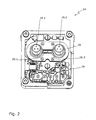
- the connection unit 14 of the relay 10 is shown in a perspective plan view.
- the magnetic flux alignment device 20 is formed as a ferromagnetic body which the two main contact terminals 16.1, 16.2 annularly surrounds and has an inner space in which two Hall sensors 26.1, 26.2 are arranged. If the relay 10 is turned on, depending on the current direction, a current flows from the main contact connection 16.1 to the main contact connection 16.2 or vice versa. Both the current flowing into the relay 10 and the current flowing out of the relay 10 induce a magnetic field which is collimated and amplified by the means 20 for aligning the magnetic flux with the Hall sensors 26.1, 26.2.
- the Hall sensor 26.1 can be designed to measure lower currents and the Hall sensor 26.2 to measure higher currents. More specifically, can be tapped at the Hall sensors 26.1, 26.2 each have a voltage corresponding to a current flowing through the relay 10 current. The tapped at the Hall sensors 26.1, 26.2 voltage is evaluated by the microcontroller 18 for this purpose.
- the microcontroller 18 can interrupt the circuit closed via the main contact connections 16.1, 16.2 by switching off the relay 10. In this case - depending on the programming of the microcontroller 18 - short-term current peaks can be ignored. In addition, the microcontroller 18 can output analog or digital current measured by the Hall sensors 26.1, 26.2.
- the device 20 for aligning the magnetic flux consists of a stack of preferably ferromagnetic sheets.
- the ferromagnetic properties of the magnetic flux orientation device 20 allow for concentration of the magnetic flux at the Hall sensors 26.1, 26.2.
- the division of the device 20 for aligning the magnetic flux in individual sheet metal layers achieved a low remanence.
- a change in the current intensity or current direction of the current flowing through the main contact terminals 16.1, 16.2 current can thus be detected quickly and accurately by the Hall sensors 26.1, 26.2.
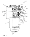
- Fig. 3 shows a further embodiment of a relay 10 'according to the invention.
- the relay 10 ' comprises a main body 12' and a connection unit 14 '.
- a coil 28 can be seen, which may be formed, for example, in one piece or as a tightening and discharge coil.
- the connection unit 14 'of the relay 10' according to the invention has, according to the in Fig. 3 illustrated embodiment, two main contact terminals 16.1 ', 16.2', the side of the relay 10 'protrude. Due to the greater distance of the main contact terminals 16.1 ', 16.2' compared to the first embodiment, the relay 10 'can be used for switching even higher currents.
- the means 20 'for aligning the magnetic flux consist of stacks of ferromagnetic sheets.
- the means 20 'for aligning the magnetic flux have at their top openings in which Hall sensors 26.1' (in Fig. 3 not shown) and 26.2 'are arranged.
- the Hall sensors 26.1 ', 26.2' are held by a T-shaped support 30 'in the opening of the means 20' for aligning the magnetic flux.
- the current flowing through the main contact terminals 16.1 ', 16.2' can be detected galvanically isolated.
- a microcontroller 18 ' can output the measured current intensity analog or digital.
- the microcontroller 18 'too high or too low currents interrupt the electrical connection between the two main contact terminals 16.1 ', 16.2' of the relay 10 '.
Landscapes
- Measuring Instrument Details And Bridges, And Automatic Balancing Devices (AREA)
Abstract
Description
- Die Erfindung bezieht sich auf ein Relais, insbesondere für den Hochstrombereich, mit mindestens einer Spule und einem beweglichen Anker, der durch den in der mindestens einen Spule erzeugbaren magnetischen Fluss einen Stromfluss über zwei Hauptkontaktanschlüsse zulässt oder unterbricht, und mit einer Strommesseinrichtung zur Messung mindestens des über die Hauptkontaktanschlüsse fließenden Stroms mittels mindestens eines Hall-Sensors.
- Relais weisen insbesondere im Hochstrombereich oftmals eine Strom- und Messeinrichtung auf, um den über die Hauptkontaktanschlüsse fließenden Strom erfassen zu können. Hierzu werden in der Regel Hall-Sensoren eingesetzt, um die fließenden Ströme nicht direkt messen zu müssen, sondern indirekt, d. h. galvanisch getrennt über das durch den Strom induzierte Magnetfeld erfassen zu können. Das magnetische Feld wird allerdings nicht nur am Hall-Sensor sondern am ganzen Relais induziert. Durch die Remanenzeffekte im Relais kann diese Magnetisierung zu Fehlern bei der Strommessung führen. Wird die Stromrichtung in einem solchen magnetisierten Relais umgedreht, so wird das vom Stromfluss erzeugte Magnetfeld um das Magnetfeld des vormagnetisierten Relais abgeschwächt. Dies wird vom Hall-Sensor als ein zu niedriger Strom interpretiert. Die Messgenauigkeit des oder der Hall-Sensoren wird dadurch erheblich beeinträchtigt.
- Der Erfindung liegt demgegenüber die Aufgabe zugrunde, eine Strommesseinrichtung für ein Relais bereitzustellen, mit der ein über die Hauptkontaktanschlüsse des Relais fließender Strom genau gemessen werden kann.
- Diese Aufgabe wird erfindungsgemäß durch ein Relais der eingangs genannten Art gelöst, bei dem um die Hauptkontaktanschlüsse eine Einrichtung zur Ausrichtung des magnetischen Flusses auf den oder die Hall-Sensoren vorgesehen ist.
- Durch die Einrichtung zur Ausrichtung des magnetischen Flusses wird der magnetische Fluss auf den oder die Hall-Sensoren konzentriert. Somit wird der Einfluss anderer magnetisierter Bereiche des Relais vermindert, wodurch die Messgenauigkeit der Strommesseinrichtung erheblich erhöht werden kann. Um einen größeren räumlichen Bereich zur Strommessung abdecken zu können, können mehrere Hall-Sensoren verwendet werden.
- In einem bevorzugten Ausführungsbeispiel der Erfindung kann die Einrichtung zur Ausrichtung des magnetischen Flusses mindestens einen die Hauptkontaktanschlüsse umschließenden und mit einem Freiraum für den oder die Hall-Sensoren versehenen ferromagnetischen Körper aufweisen. In den ferromagnetischen Körper wird durch den durch die Hauptkontaktanschlüsse fließenden Strom ein starkes Magnetfeld induziert. In einem Freiraum (Luftspalt) des ferromagnetischen Körpers, in dem der oder die Hall-Sensoren angeordnet sind, ist das induzierte Magnetfeld besonders hoch, sodass die Strommesseinrichtung eine sehr hohe Genauigkeit aufweisen kann.
- Vorzugsweise können zwei ferromagnetische Körper vorgesehen sein, die jeweils einen Hauptkontaktanschluss umgreifen und jeweils einen Freiraum aufweisen, in dem ein Hall-Sensor angeordnet ist. Sollen mit dem Relais sehr hohe Ströme geschaltet werden können, so ist es vorteilhaft, zwei räumlich voneinander beabstandete Hauptkontaktanschlüsse mit jeweils eigenen ferromagnetischen Körpern vorzusehen. Die den jeweiligen Hauptkontaktanschlüssen zugeordneten Hall-Sensoren können derart angeordnet sein, dass ein Hall-Sensor das Magnetfeld des einfließenden Stroms und ein anderer Hall-Sensor das Magnetfeld des aus dem Relais herausfließenden Stroms erfasst. Durch einen Vergleich der beiden Ströme können unerwünschte Leckströme im Relais festgestellt werden.
- In einem weiteren Ausführungsbeispiel der Erfindung kann die Strommesseinrichtung des Relais derart ausgebildet sein, dass der ferromagnetische Körper ringförmig beide Hauptkontakte umgreift und zwischen den Hauptkontakten in einem inneren Freiraum mindestens ein Hall-Sensor angeordnet ist. Hierbei sind die beiden Hauptkontakte parallel und nebeneinander angeordnet. Im Freiraum des ferromagnetischen Körpers können ein oder mehrere Hall-Sensor/en angeordnet sein, um in das Relais ein- und ausfließende Ströme zu messen.
- In weiterer Ausgestaltung der Erfindung sind der oder die ferromagnetischen Körper aus einem Stapel von ferromagnetischen Blechen gebildet. Durch die Aufteilung des ferromagnetischen Körpers in ein Bündel einzelner Bleche kann die Remanenz des ferromagnetischen Körpers deutlich reduziert werden. Als Werkstoff für den Blechstapel kann beispielsweise ein veredeltes Elektroblech eingesetzt werden. Die Verwendung eines Stapels ferromagnetischer Bleche sorgt somit nicht nur für eine Bündelung des magnetischen Flusses, sondern auch für eine Reduktion der Remanenz. Die Messgenauigkeit der Strommesseinrichtung des Relais kann hierdurch weiter erhöht werden.
- Weiterhin können mit der Strommesseinrichtung bevorzugt über die Hauptkontakte fließende Ströme in beide Stromrichtungen messbar sein. Hierdurch können die Einsatzmöglichkeiten des Relais wesentlich erweitert werden.
- In einem weiteren Ausführungsbeispiel der Erfindung kann die Strommesseinrichtung einen Mikrocontroller aufweisen, mit dem von dem oder den Hall-Sensor/en gemessene Ströme erfassbar und weiterverarbeitbar sind. Durch den Einsatz des Mikrocontrollers kann ein automatisches Abschalten des Relais bei Überstrom erreicht werden. Über den Mikrocontroller kann so eine Sicherheitsabschaltung des Relais auslösbar sein. Hierzu können beispielsweise frei programmierbare Überstromabschaltschwellen im Mikrocontroller hinterlegt werden. Darüber hinaus kann durch den Mikrocontroller eine Sicherungskennlinie einer herkömmlichen Einwegsicherung nachgebildet werden.
- Weiterhin bietet der Mikrocontroller die Möglichkeit, eine Nachbildung einer herkömmlichen Schmelzsicherungskennlinie als Auslösecharakteristik zu verwenden. Der Mikrocontroller wertet dann das von der Strommesseinrichtung gemessene Signal aus und kann durch einen Vergleich mit der hinterlegten Schmelzsicherungskennlinie die Beschädigung eines Bauteils im Stromkreis erkennen und im Relais den Stromkreis unterbrechen.
- Ein weiterer Vorteil des Mikrocontrollers ist die Möglichkeit des Ein- und Ausschaltens des Relais über einen Steuereingang. Durch den Mikrocontroller können weiterhin auch eine Unterspannungsabschaltschwelle sowie eine Übertemperaturabschaltung und die Ausgabe eines Statussignals zur Anzeige des Betriebszustands realisiert werden. Am Mikrocontroller kann auch eine minimale Versorgungsspannung vorgegeben werden. Der Mikrocontroller kann dann so programmiert werden, dass das Relais bei einer Unterschreitung dieser Versorgungsspannung nicht eingeschaltet werden kann, um beispielsweise eine schwache Batterie durch einen über das Relais zuschaltbaren elektrischen Verbraucher nicht weiter zu belasten. Schließlich können durch den Mikrocontroller kurzzeitige Stromspitzen von der Beeinflussung des Messergebnisses ausgeschlossen werden. So lassen sich beispielsweise Fehlinterpretationen der Messergebnisse infolge von Einschaltstromspitzen dadurch vermeiden, dass der Mikrocontroller die Strommesseinrichtung vom Einschaltzeitpunkt an für eine variable Zeit ausblendet. Auch Betriebsstromspitzen können vom Mikrocontroller erkannt und "ausgeblendet" werden.
- Vorzugsweise können die über den oder die Hall-Sensor/en gemessenen Ströme über den Mikrocontroller analog/digital wandelbar sein. Der Mikrocontroller bietet hierdurch weitere Verarbeitungsmöglichkeiten des gemessenen Stroms. Der gemessene Strom kann beispielsweise digital gewandelt und weiterverarbeitet werden. Die Messgenauigkeit der Strommesseinrichtung bleibt dabei erhalten.
- Das erfindungsgemäße Relais kann überall dort eingesetzt werden, wo das Relais als Sicherung dient oder Ströme gemessen und ausgegeben werden sollen.
- Nachfolgend werden Ausführungsbeispiele der Erfindung in der Zeichnung näher beschrieben.
- Es zeigen:
- Fig. 1
- eine perspektivische, teilweise geschnittene Darstellung eines ersten Ausführungsbeispiels der Erfindung;
- Fig. 2
- eine perspektivische Darstellung einer Anschlusseinheit aus
Fig. 1 ; - Fig. 3
- eine perspektivische, teilweise geschnittene Darstellung eines zweiten Ausführungsbeispiels eines erfindungsgemäßen Relais.
-
Fig. 1 zeigt ein erstes Ausführungsbeispiel eines erfindungsgemäßen Relais 10, das einen Grundkörper 12 und eine Anschlusseinheit 14 umfasst. Die Anschlusseinheit 14 weist zwei Hauptkontaktanschlüsse 16.1, 16.2 auf. Die Hauptkontaktanschlüsse 16.1, 16.2 können durch eine Hauptkontaktbrücke (nicht gezeigt) durch einen Schaltvorgang im Relais elektrisch verbunden werden. Neben den Hauptkontaktanschlüssen 16.1, 16.2 weist die Anschlusseinheit 14 eine Strommesseinrichtung auf, die einen Mikrocontroller 18 und eine Einrichtung 20 zur Ausrichtung des magnetischen Flusses umfasst. Weiterhin weist die Anschlusseinheit 14 Steuerkontakte 22 zur Steuerung des Relais 10 auf. Das Relais 10 kann über einen Seitenflansch 24 beispielsweise in einem Fahrzeug befestigt werden. - In
Fig. 2 ist die Anschlusseinheit 14 des Relais 10 in einer perspektivischen Draufsicht dargestellt. In diesem inFig. 2 dargestellten ersten Ausführungsbeispiel der Erfindung ist die Einrichtung 20 zur Ausrichtung des magnetischen Flusses als ein ferromagnetischer Körper ausgebildet, der die beiden Hauptkontaktanschlüsse 16.1, 16.2 ringförmig umgreift und einen inneren Freiraum aufweist, in dem zwei Hall-Sensoren 26.1, 26.2 angeordnet sind. Wird das Relais 10 eingeschaltet, fließt je nach Stromrichtung ein Strom vom Hauptkontaktanschluss 16.1 zum Hauptkontaktanschluss 16.2 oder umgekehrt. Sowohl der in das Relais 10 hineinfließende Strom als auch der aus dem Relais 10 herausfließende Strom induziert ein Magnetfeld, das von der Einrichtung 20 zur Ausrichtung des magnetischen Flusses auf die Hall-Sensoren 26.1, 26.2 gebündelt und verstärkt wird. Der Hall-Sensor 26.1 kann dabei zur Messung niedrigerer Ströme und der Hall-Sensor 26.2 zur Messung höherer Ströme ausgelegt sein. Genauer gesagt, kann an den Hall-Sensoren 26.1, 26.2 jeweils eine Spannung abgegriffen werden, die einem durch das Relais 10 fließenden Strom entspricht. Die an den Hall-Sensoren 26.1, 26.2 abgegriffene Spannung wird hierzu vom Mikrocontroller 18 ausgewertet. - Überschreitet der durch das Relais 10 fließende Strom einen bestimmten Schwellwert, so kann der Mikrocontroller 18 durch ein Ausschalten des Relais 10 den über die Hauptkontaktanschlüsse 16.1, 16.2 geschlossenen Stromkreis unterbrechen. Dabei können - je nach Programmierung des Mikrocontrollers 18 - kurzzeitige Stromspitzen ignoriert werden. Darüber hinaus kann der Mikrocontroller 18 die von den Hall-Sensoren 26.1, 26.2 gemessene Stromstärke analog oder digital ausgeben.
- Aus einer Zusammenschau der
Fig. 1 und2 wird deutlich, dass die Einrichtung 20 zur Ausrichtung des magnetischen Flusses aus einem Stapel vorzugsweise ferromagnetischer Bleche besteht. Die ferromagnetischen Eigenschaften der Einrichtung 20 zur Ausrichtung des magnetischen Flusses ermöglichen eine Konzentration des magnetischen Flusses an den Hall-Sensoren 26.1, 26.2. Gleichzeitig wird durch die Aufteilung der Einrichtung 20 zur Ausrichtung des magnetischen Flusses in einzelne Blechlagen eine niedrige Remanenz erreicht. Eine Änderung der Stromstärke oder Stromrichtung des durch die Hauptkontaktanschlüsse 16.1, 16.2 fließenden Stroms kann somit schnell und genau durch die Hall-Sensoren 26.1, 26.2 erfasst werden. -
Fig. 3 zeigt ein weiteres Ausführungsbeispiel eines erfindungsgemäßen Relais 10'. Das Relais 10' umfasst einen Grundkörper 12' und eine Anschlusseinheit 14'. In der teilweise geschnittenen Ansicht des Grundkörpers 12' ist eine Spule 28 erkennbar, die beispielsweise einteilig oder als Anzugs- und Abwurfspule ausgebildet sein kann. Die Anschlusseinheit 14' des erfindungsgemäßen Relais 10' weist gemäß dem inFig. 3 dargestellten Ausführungsbeispiel zwei Hauptkontaktanschlüsse 16.1', 16.2' auf, die seitlich vom Relais 10' abstehen. Durch den im Vergleich zum ersten Ausführungsbeispiel größeren Abstand der Hauptkontaktanschlüsse 16.1', 16.2' kann das Relais 10' zum Schalten noch höherer Ströme verwendet werden. Zur Steuerung des Relais 10' sind an dessen Ober- und Unterseite Steuerkontakte 22' angeordnet. Um die beiden Hauptkontaktanschlüsse 16.1', 16.2' befinden sich jeweils Einrichtungen 20' zur Ausrichtung des magnetischen Flusses. Wie beim Ausführungsbeispiel aus denFig. 1 und2 bestehen die Einrichtungen 20' zur Ausrichtung des magnetischen Flusses aus Stapeln ferromagnetischer Bleche. Die Einrichtungen 20' zur Ausrichtung des magnetischen Flusses weisen an ihrer Oberseite Öffnungen auf, in denen Hall-Sensoren 26.1' (inFig. 3 nicht gezeigt) und 26.2' angeordnet sind. Die Hall-Sensoren 26.1', 26.2' werden von einem T-förmigen Träger 30' in der Öffnung der Einrichtung 20' zur Ausrichtung des magnetischen Flusses gehalten. Hierdurch kann ebenso wie im oben beschriebenen Ausführungsbeispiel der durch die Hauptkontaktanschlüsse 16.1', 16.2' fließende Strom galvanisch getrennt erfasst werden. Ein Mikrocontroller 18' kann die gemessene Stromstärke analog oder digital ausgeben. Gleichzeitig kann der Mikrocontroller 18' bei zu hohen oder zu niedrigen Strömen die elektrische Verbindung zwischen den beiden Hauptkontaktanschlüssen 16.1`, 16.2' des Relais 10' unterbrechen.
Claims (9)
- Relais (10), insbesondere für den Hochstrombereich, mit mindestens einer Spule (28) und einem beweglichen Anker, der durch den in der mindestens einen Spule (28) erzeugbaren magnetischen Fluss einen Stromfluss über zwei Hauptkontaktanschlüsse (16.1, 16.2; 16.1`, 16.2') zulässt oder unterbricht, und mit einer Strommesseinrichtung zur Messung mindestens des über die Hauptkontaktanschlüsse (16.1, 16.2; 16.1', 16.2') fließenden Stroms mittels mindestens eines Hall-Sensors (26.1, 26.2; 26.2'), dadurch gekennzeichnet, dass um die Hauptkontaktanschlüsse (16.1, 16.2; 16.1', 16.2`) eine Einrichtung (20, 20') zur Ausrichtung des magnetischen Flusses auf den oder die Hall-Sensor/en (26.1, 26.2; 26.2') vorgesehen ist.
- Relais nach Anspruch 1, dadurch gekennzeichnet, dass die Einrichtung (20, 20') zur Ausrichtung des magnetischen Flusses mindestens einen die Hauptkontaktanschlüsse (16.1, 16.2; 16.1', 16.2') umschließenden und mit einem Freiraum für den oder die Hall-Sensor/en (26.1, 26.2; 26.2') versehenen ferromagnetischen Körper aufweist.
- Relais nach Anspruch 2, dadurch gekennzeichnet, dass zwei ferromagnetische Körper (20') vorgesehen sind, die jeweils einen Hauptkontaktanschluss (16.1', 16.2') umgreifen und jeweils einen Freiraum aufweisen, in dem ein Hall-Sensor (26.2') angeordnet ist.
- Relais nach Anspruch 2, dadurch gekennzeichnet, dass der ferromagnetische Körper (20) ringförmig beide Hauptkontaktanschlüsse (16.1, 26.2) umgreift und zwischen den Hauptkontaktanschlüssen (16.1, 16.2) in einem inneren Freiraum mindestens ein Hall-Sensor (26.1, 26.2) angeordnet ist.
- Relais nach einem der Ansprüche 1 bis 4, dadurch gekennzeichnet, dass der oder die ferromagnetischen Körper (20, 20') aus einem Stapel von ferromagnetischen Blechen gebildet sind.
- Relais nach einem der Ansprüche 1 bis 5, dadurch gekennzeichnet, dass mit der Strommesseinrichtung über die Hauptkontaktanschlüsse (16.1, 16.2; 16.1`, 16.2') fließende Ströme in beide Stromrichtungen messbar sind.
- Relais nach einem der Ansprüche 1 bis 6, dadurch gekennzeichnet, dass die Strommesseinrichtung einen Mikrocontroller (18, 18') aufweist, mit dem von dem oder den Hall-Sensor/en (26.1, 26.2; 26.2') gemessene Ströme erfassbar und weiterverarbeitbar sind.
- Relais nach Anspruch 7, dadurch gekennzeichnet, dass die Ströme über den Mikrocontroller (18, 18') analog/digital-wandelbar sind.
- Relais nach Anspruch 7 oder 8, dadurch gekennzeichnet, dass über den Mikrocontroller (18, 18') eine Sicherheitsabschaltung des Relais (10, 10') auslösbar ist.
Applications Claiming Priority (1)
| Application Number | Priority Date | Filing Date | Title |
|---|---|---|---|
| DE102010018739A DE102010018739A1 (de) | 2010-04-29 | 2010-04-29 | Relais, insbesondere für den Hochstrombereich |
Publications (2)
| Publication Number | Publication Date |
|---|---|
| EP2383763A1 true EP2383763A1 (de) | 2011-11-02 |
| EP2383763B1 EP2383763B1 (de) | 2021-07-21 |
Family
ID=44484982
Family Applications (1)
| Application Number | Title | Priority Date | Filing Date |
|---|---|---|---|
| EP11002953.5A Active EP2383763B1 (de) | 2010-04-29 | 2011-04-08 | Relais, insbesondere für den Hochstrombereich |
Country Status (4)
| Country | Link |
|---|---|
| US (1) | US8829892B2 (de) |
| EP (1) | EP2383763B1 (de) |
| CA (1) | CA2737547C (de) |
| DE (1) | DE102010018739A1 (de) |
Cited By (1)
| Publication number | Priority date | Publication date | Assignee | Title |
|---|---|---|---|---|
| EP3474026A1 (de) * | 2017-10-23 | 2019-04-24 | Kissling Elektrotechnik GmbH | Kontaktanordnung mit strommesseinrichtung |
Families Citing this family (3)
| Publication number | Priority date | Publication date | Assignee | Title |
|---|---|---|---|---|
| DE102015006051B4 (de) * | 2015-05-15 | 2021-06-17 | Tdk-Micronas Gmbh | Masseband mit einer Magnetfeldmesseinrichtung und Verfahren zur Messung eines durch das Masseband fließenden Stroms mit der Magnetfeldeinrichtung |
| GB2543494B (en) * | 2015-10-16 | 2021-11-10 | Johnson Electric Int Ag | Improvements in or relating to electrical disconnect contactors |
| DE102018120984B4 (de) * | 2018-08-28 | 2022-03-31 | Tdk Electronics Ag | Schaltvorrichtung |
Citations (4)
| Publication number | Priority date | Publication date | Assignee | Title |
|---|---|---|---|---|
| WO1990011529A1 (en) * | 1989-03-23 | 1990-10-04 | Abb Strömberg Kojeet Oy | Apparatus and method for measuring electric current in conditions of high interference |
| WO1999036928A1 (en) * | 1998-01-14 | 1999-07-22 | General Electric Company | Circuit breaker having hall effect sensors |
| EP1037240A2 (de) * | 1999-03-12 | 2000-09-20 | Eaton Corporation | Magnetfluss Konzentrationsschirm für ein Überstromrelais |
| US6252389B1 (en) * | 1998-03-18 | 2001-06-26 | Mitsubishi Denki Kabushiki Kaisha | Current detector having magnetic core for concentrating a magnetic flux near a hall-effect sensor, and power switch apparatus incorporating same |
Family Cites Families (10)
| Publication number | Priority date | Publication date | Assignee | Title |
|---|---|---|---|---|
| AT368814B (de) * | 1979-10-05 | 1982-11-10 | Vmw Ranshofen Berndorf Ag | Vorrichtung zur messung der stromstaerke in stromschienen insbesondere von elektrolysen zur raffination von kupfer |
| FR2577070B1 (fr) | 1985-02-05 | 1988-02-05 | Vedette Horlogerie | Interface pour relais bistable |
| US5744923A (en) * | 1996-11-22 | 1998-04-28 | National Environmental Products, Ltd., Inc. | Microprocessor-based controller for actuator motors with capacitive power backup and method therefor |
| DE29724595U1 (de) | 1997-10-08 | 2002-05-08 | Kissling Elektrotechnik GmbH & Co. KG, 72218 Wildberg | Bistabiles Relais, insbesondere für den Hochstrombereich |
| DE10022722C5 (de) | 2000-05-10 | 2008-07-10 | Pilz Gmbh & Co. Kg | Sicherheitsschaltgerät zum sicheren Ein- und Ausschalten eines elektrischen Verbrauchers |
| US6873514B2 (en) | 2001-06-05 | 2005-03-29 | Trombetta, Llc | Integrated solenoid system |
| WO2003046940A1 (en) | 2001-11-29 | 2003-06-05 | Matsushita Electric Works, Ltd. | Elecromagnetic switching apparatus |
| DE102007035325A1 (de) | 2007-07-27 | 2009-01-29 | Robert Bosch Gmbh | Stiftförmiges Kontaktelement und Steckverbindung |
| US8446046B2 (en) * | 2008-10-03 | 2013-05-21 | Access Business Group International Llc | Power system |
| KR101433212B1 (ko) * | 2010-04-14 | 2014-08-22 | 지멘스 악티엔게젤샤프트 | 코어 내의 자기 특성 변수를 검출하기 위한 방법 및 장치 |
-
2010
- 2010-04-29 DE DE102010018739A patent/DE102010018739A1/de not_active Ceased
-
2011
- 2011-04-08 EP EP11002953.5A patent/EP2383763B1/de active Active
- 2011-04-18 CA CA2737547A patent/CA2737547C/en active Active
- 2011-04-25 US US13/093,219 patent/US8829892B2/en active Active
Patent Citations (4)
| Publication number | Priority date | Publication date | Assignee | Title |
|---|---|---|---|---|
| WO1990011529A1 (en) * | 1989-03-23 | 1990-10-04 | Abb Strömberg Kojeet Oy | Apparatus and method for measuring electric current in conditions of high interference |
| WO1999036928A1 (en) * | 1998-01-14 | 1999-07-22 | General Electric Company | Circuit breaker having hall effect sensors |
| US6252389B1 (en) * | 1998-03-18 | 2001-06-26 | Mitsubishi Denki Kabushiki Kaisha | Current detector having magnetic core for concentrating a magnetic flux near a hall-effect sensor, and power switch apparatus incorporating same |
| EP1037240A2 (de) * | 1999-03-12 | 2000-09-20 | Eaton Corporation | Magnetfluss Konzentrationsschirm für ein Überstromrelais |
Cited By (1)
| Publication number | Priority date | Publication date | Assignee | Title |
|---|---|---|---|---|
| EP3474026A1 (de) * | 2017-10-23 | 2019-04-24 | Kissling Elektrotechnik GmbH | Kontaktanordnung mit strommesseinrichtung |
Also Published As
| Publication number | Publication date |
|---|---|
| CA2737547C (en) | 2017-06-13 |
| US8829892B2 (en) | 2014-09-09 |
| EP2383763B1 (de) | 2021-07-21 |
| US20110267034A1 (en) | 2011-11-03 |
| CA2737547A1 (en) | 2011-10-29 |
| DE102010018739A1 (de) | 2011-11-03 |
Similar Documents
| Publication | Publication Date | Title |
|---|---|---|
| EP2593949B1 (de) | Überstromschalter, verwendung eines überstromschalters und elektrokraftfahrzeug mit einem überstromschalter | |
| DE102021123868B4 (de) | Elektrisches Schaltelement mit Statusindikator und Bausatz für ein solches | |
| DE102015224658B4 (de) | Elektromechanischer Schutzschalter | |
| DE102015104211A1 (de) | Sicherheitsschaltgerät zum fehlersicheren Abschalten einer elektrischen Last | |
| DE202015106694U1 (de) | Schutzschalter | |
| EP2878057A2 (de) | Vorrichtung zum sicheren schalten einer photovoltaikanlage | |
| DE102018120984A1 (de) | Schaltvorrichtung | |
| EP3226013A1 (de) | Differenzstromsensor | |
| WO2009010154A2 (de) | Schutzschalter mit magnetfeldsensitivem sensor | |
| EP2383763B1 (de) | Relais, insbesondere für den Hochstrombereich | |
| WO2021213769A1 (de) | Vorrichtung zur begrenzung eines kurzschlussstromes in einem laststufenschalter sowie laststufenschalter mit dieser vorrichtung | |
| DE202019100399U1 (de) | Lasttrennschaltervorrichtung und Schaltersicherungsvorrichtung mit Sicherung | |
| EP3115798A1 (de) | Batteriesensoreinheit mit widerstandselement | |
| DE102015121264A1 (de) | Leistungsschütz und Verfahren zur Funktionsprüfung eines Leistungsschützes | |
| EP2383765B1 (de) | Relais mit integrierter Sicherheitsbeschaltung | |
| EP3433871B1 (de) | Vorrichtung zur messung eines zustands eines elektrischen schalters, elektrischer schalter und verfahren zur messung eines zustands eines elektrischen schalters | |
| EP2115759B1 (de) | Schutzeinrichtung und verfahren zu deren betrieb | |
| DE102016224013A1 (de) | Differenzstromsensor | |
| DE102004062267A1 (de) | Verfahren und Vorrichtung zum sicheren Betrieb eines Schaltgerätes | |
| DE102010061766A1 (de) | Schalter, insbesondere Leistungsschalter für Niederspannungen | |
| DE1588805C3 (de) | Selektive Kurzschlußeinrichtung für Gleichspannungsnetze | |
| DE102024206874A1 (de) | Auslösevorrichtung und Fehlerstromschutzschalter | |
| DE102024004486A1 (de) | Schaltvorrichtung und Betriebsvorrichtung mit einer Schaltvorrichtung | |
| WO2026104287A1 (de) | Leistungselektronischer schalter | |
| AT218616B (de) | Vielfachmeßinstrument mit einer Überlastungsschutzeinrichtung |
Legal Events
| Date | Code | Title | Description |
|---|---|---|---|
| AK | Designated contracting states |
Kind code of ref document: A1 Designated state(s): AL AT BE BG CH CY CZ DE DK EE ES FI FR GB GR HR HU IE IS IT LI LT LU LV MC MK MT NL NO PL PT RO RS SE SI SK SM TR |
|
| AX | Request for extension of the european patent |
Extension state: BA ME |
|
| PUAI | Public reference made under article 153(3) epc to a published international application that has entered the european phase |
Free format text: ORIGINAL CODE: 0009012 |
|
| 17P | Request for examination filed |
Effective date: 20120420 |
|
| 17Q | First examination report despatched |
Effective date: 20150626 |
|
| APBK | Appeal reference recorded |
Free format text: ORIGINAL CODE: EPIDOSNREFNE |
|
| APBN | Date of receipt of notice of appeal recorded |
Free format text: ORIGINAL CODE: EPIDOSNNOA2E |
|
| APBR | Date of receipt of statement of grounds of appeal recorded |
Free format text: ORIGINAL CODE: EPIDOSNNOA3E |
|
| APAF | Appeal reference modified |
Free format text: ORIGINAL CODE: EPIDOSCREFNE |
|
| APBX | Invitation to file observations in appeal sent |
Free format text: ORIGINAL CODE: EPIDOSNOBA2E |
|
| RAP1 | Party data changed (applicant data changed or rights of an application transferred) |
Owner name: TE CONNECTIVITY KISSLING PRODUCTS GMBH |
|
| APBT | Appeal procedure closed |
Free format text: ORIGINAL CODE: EPIDOSNNOA9E |
|
| GRAP | Despatch of communication of intention to grant a patent |
Free format text: ORIGINAL CODE: EPIDOSNIGR1 |
|
| STAA | Information on the status of an ep patent application or granted ep patent |
Free format text: STATUS: GRANT OF PATENT IS INTENDED |
|
| INTG | Intention to grant announced |
Effective date: 20210318 |
|
| GRAS | Grant fee paid |
Free format text: ORIGINAL CODE: EPIDOSNIGR3 |
|
| GRAA | (expected) grant |
Free format text: ORIGINAL CODE: 0009210 |
|
| STAA | Information on the status of an ep patent application or granted ep patent |
Free format text: STATUS: THE PATENT HAS BEEN GRANTED |
|
| AK | Designated contracting states |
Kind code of ref document: B1 Designated state(s): AL AT BE BG CH CY CZ DE DK EE ES FI FR GB GR HR HU IE IS IT LI LT LU LV MC MK MT NL NO PL PT RO RS SE SI SK SM TR |
|
| REG | Reference to a national code |
Ref country code: GB Ref legal event code: FG4D Free format text: NOT ENGLISH |
|
| REG | Reference to a national code |
Ref country code: CH Ref legal event code: EP |
|
| REG | Reference to a national code |
Ref country code: DE Ref legal event code: R096 Ref document number: 502011017178 Country of ref document: DE |
|
| REG | Reference to a national code |
Ref country code: AT Ref legal event code: REF Ref document number: 1413363 Country of ref document: AT Kind code of ref document: T Effective date: 20210815 |
|
| REG | Reference to a national code |
Ref country code: IE Ref legal event code: FG4D Free format text: LANGUAGE OF EP DOCUMENT: GERMAN |
|
| REG | Reference to a national code |
Ref country code: LT Ref legal event code: MG9D |
|
| REG | Reference to a national code |
Ref country code: NL Ref legal event code: MP Effective date: 20210721 |
|
| PG25 | Lapsed in a contracting state [announced via postgrant information from national office to epo] |
Ref country code: SE Free format text: LAPSE BECAUSE OF FAILURE TO SUBMIT A TRANSLATION OF THE DESCRIPTION OR TO PAY THE FEE WITHIN THE PRESCRIBED TIME-LIMIT Effective date: 20210721 Ref country code: HR Free format text: LAPSE BECAUSE OF FAILURE TO SUBMIT A TRANSLATION OF THE DESCRIPTION OR TO PAY THE FEE WITHIN THE PRESCRIBED TIME-LIMIT Effective date: 20210721 Ref country code: NL Free format text: LAPSE BECAUSE OF FAILURE TO SUBMIT A TRANSLATION OF THE DESCRIPTION OR TO PAY THE FEE WITHIN THE PRESCRIBED TIME-LIMIT Effective date: 20210721 Ref country code: RS Free format text: LAPSE BECAUSE OF FAILURE TO SUBMIT A TRANSLATION OF THE DESCRIPTION OR TO PAY THE FEE WITHIN THE PRESCRIBED TIME-LIMIT Effective date: 20210721 Ref country code: NO Free format text: LAPSE BECAUSE OF FAILURE TO SUBMIT A TRANSLATION OF THE DESCRIPTION OR TO PAY THE FEE WITHIN THE PRESCRIBED TIME-LIMIT Effective date: 20211021 Ref country code: PT Free format text: LAPSE BECAUSE OF FAILURE TO SUBMIT A TRANSLATION OF THE DESCRIPTION OR TO PAY THE FEE WITHIN THE PRESCRIBED TIME-LIMIT Effective date: 20211122 Ref country code: ES Free format text: LAPSE BECAUSE OF FAILURE TO SUBMIT A TRANSLATION OF THE DESCRIPTION OR TO PAY THE FEE WITHIN THE PRESCRIBED TIME-LIMIT Effective date: 20210721 Ref country code: FI Free format text: LAPSE BECAUSE OF FAILURE TO SUBMIT A TRANSLATION OF THE DESCRIPTION OR TO PAY THE FEE WITHIN THE PRESCRIBED TIME-LIMIT Effective date: 20210721 Ref country code: BG Free format text: LAPSE BECAUSE OF FAILURE TO SUBMIT A TRANSLATION OF THE DESCRIPTION OR TO PAY THE FEE WITHIN THE PRESCRIBED TIME-LIMIT Effective date: 20211021 Ref country code: LT Free format text: LAPSE BECAUSE OF FAILURE TO SUBMIT A TRANSLATION OF THE DESCRIPTION OR TO PAY THE FEE WITHIN THE PRESCRIBED TIME-LIMIT Effective date: 20210721 |
|
| PG25 | Lapsed in a contracting state [announced via postgrant information from national office to epo] |
Ref country code: PL Free format text: LAPSE BECAUSE OF FAILURE TO SUBMIT A TRANSLATION OF THE DESCRIPTION OR TO PAY THE FEE WITHIN THE PRESCRIBED TIME-LIMIT Effective date: 20210721 Ref country code: LV Free format text: LAPSE BECAUSE OF FAILURE TO SUBMIT A TRANSLATION OF THE DESCRIPTION OR TO PAY THE FEE WITHIN THE PRESCRIBED TIME-LIMIT Effective date: 20210721 Ref country code: GR Free format text: LAPSE BECAUSE OF FAILURE TO SUBMIT A TRANSLATION OF THE DESCRIPTION OR TO PAY THE FEE WITHIN THE PRESCRIBED TIME-LIMIT Effective date: 20211022 |
|
| REG | Reference to a national code |
Ref country code: DE Ref legal event code: R097 Ref document number: 502011017178 Country of ref document: DE |
|
| PG25 | Lapsed in a contracting state [announced via postgrant information from national office to epo] |
Ref country code: DK Free format text: LAPSE BECAUSE OF FAILURE TO SUBMIT A TRANSLATION OF THE DESCRIPTION OR TO PAY THE FEE WITHIN THE PRESCRIBED TIME-LIMIT Effective date: 20210721 |
|
| PLBE | No opposition filed within time limit |
Free format text: ORIGINAL CODE: 0009261 |
|
| STAA | Information on the status of an ep patent application or granted ep patent |
Free format text: STATUS: NO OPPOSITION FILED WITHIN TIME LIMIT |
|
| PG25 | Lapsed in a contracting state [announced via postgrant information from national office to epo] |
Ref country code: SM Free format text: LAPSE BECAUSE OF FAILURE TO SUBMIT A TRANSLATION OF THE DESCRIPTION OR TO PAY THE FEE WITHIN THE PRESCRIBED TIME-LIMIT Effective date: 20210721 Ref country code: SK Free format text: LAPSE BECAUSE OF FAILURE TO SUBMIT A TRANSLATION OF THE DESCRIPTION OR TO PAY THE FEE WITHIN THE PRESCRIBED TIME-LIMIT Effective date: 20210721 Ref country code: RO Free format text: LAPSE BECAUSE OF FAILURE TO SUBMIT A TRANSLATION OF THE DESCRIPTION OR TO PAY THE FEE WITHIN THE PRESCRIBED TIME-LIMIT Effective date: 20210721 Ref country code: EE Free format text: LAPSE BECAUSE OF FAILURE TO SUBMIT A TRANSLATION OF THE DESCRIPTION OR TO PAY THE FEE WITHIN THE PRESCRIBED TIME-LIMIT Effective date: 20210721 Ref country code: CZ Free format text: LAPSE BECAUSE OF FAILURE TO SUBMIT A TRANSLATION OF THE DESCRIPTION OR TO PAY THE FEE WITHIN THE PRESCRIBED TIME-LIMIT Effective date: 20210721 Ref country code: AL Free format text: LAPSE BECAUSE OF FAILURE TO SUBMIT A TRANSLATION OF THE DESCRIPTION OR TO PAY THE FEE WITHIN THE PRESCRIBED TIME-LIMIT Effective date: 20210721 |
|
| 26N | No opposition filed |
Effective date: 20220422 |
|
| PG25 | Lapsed in a contracting state [announced via postgrant information from national office to epo] |
Ref country code: IT Free format text: LAPSE BECAUSE OF FAILURE TO SUBMIT A TRANSLATION OF THE DESCRIPTION OR TO PAY THE FEE WITHIN THE PRESCRIBED TIME-LIMIT Effective date: 20210721 |
|
| REG | Reference to a national code |
Ref country code: CH Ref legal event code: PL |
|
| GBPC | Gb: european patent ceased through non-payment of renewal fee |
Effective date: 20220408 |
|
| REG | Reference to a national code |
Ref country code: BE Ref legal event code: MM Effective date: 20220430 |
|
| PG25 | Lapsed in a contracting state [announced via postgrant information from national office to epo] |
Ref country code: MC Free format text: LAPSE BECAUSE OF FAILURE TO SUBMIT A TRANSLATION OF THE DESCRIPTION OR TO PAY THE FEE WITHIN THE PRESCRIBED TIME-LIMIT Effective date: 20210721 Ref country code: LU Free format text: LAPSE BECAUSE OF NON-PAYMENT OF DUE FEES Effective date: 20220408 Ref country code: LI Free format text: LAPSE BECAUSE OF NON-PAYMENT OF DUE FEES Effective date: 20220430 Ref country code: GB Free format text: LAPSE BECAUSE OF NON-PAYMENT OF DUE FEES Effective date: 20220408 Ref country code: FR Free format text: LAPSE BECAUSE OF NON-PAYMENT OF DUE FEES Effective date: 20220430 Ref country code: CH Free format text: LAPSE BECAUSE OF NON-PAYMENT OF DUE FEES Effective date: 20220430 |
|
| PG25 | Lapsed in a contracting state [announced via postgrant information from national office to epo] |
Ref country code: BE Free format text: LAPSE BECAUSE OF NON-PAYMENT OF DUE FEES Effective date: 20220430 |
|
| PG25 | Lapsed in a contracting state [announced via postgrant information from national office to epo] |
Ref country code: IE Free format text: LAPSE BECAUSE OF NON-PAYMENT OF DUE FEES Effective date: 20220408 |
|
| REG | Reference to a national code |
Ref country code: AT Ref legal event code: MM01 Ref document number: 1413363 Country of ref document: AT Kind code of ref document: T Effective date: 20220408 |
|
| PG25 | Lapsed in a contracting state [announced via postgrant information from national office to epo] |
Ref country code: AT Free format text: LAPSE BECAUSE OF NON-PAYMENT OF DUE FEES Effective date: 20220408 |
|
| PG25 | Lapsed in a contracting state [announced via postgrant information from national office to epo] |
Ref country code: HU Free format text: LAPSE BECAUSE OF FAILURE TO SUBMIT A TRANSLATION OF THE DESCRIPTION OR TO PAY THE FEE WITHIN THE PRESCRIBED TIME-LIMIT; INVALID AB INITIO Effective date: 20110408 |
|
| PG25 | Lapsed in a contracting state [announced via postgrant information from national office to epo] |
Ref country code: MK Free format text: LAPSE BECAUSE OF FAILURE TO SUBMIT A TRANSLATION OF THE DESCRIPTION OR TO PAY THE FEE WITHIN THE PRESCRIBED TIME-LIMIT Effective date: 20210721 Ref country code: CY Free format text: LAPSE BECAUSE OF FAILURE TO SUBMIT A TRANSLATION OF THE DESCRIPTION OR TO PAY THE FEE WITHIN THE PRESCRIBED TIME-LIMIT Effective date: 20210721 |
|
| PG25 | Lapsed in a contracting state [announced via postgrant information from national office to epo] |
Ref country code: TR Free format text: LAPSE BECAUSE OF FAILURE TO SUBMIT A TRANSLATION OF THE DESCRIPTION OR TO PAY THE FEE WITHIN THE PRESCRIBED TIME-LIMIT Effective date: 20210721 |
|
| PG25 | Lapsed in a contracting state [announced via postgrant information from national office to epo] |
Ref country code: MT Free format text: LAPSE BECAUSE OF FAILURE TO SUBMIT A TRANSLATION OF THE DESCRIPTION OR TO PAY THE FEE WITHIN THE PRESCRIBED TIME-LIMIT Effective date: 20210721 |
|
| PGFP | Annual fee paid to national office [announced via postgrant information from national office to epo] |
Ref country code: DE Payment date: 20250305 Year of fee payment: 15 |