EP2383486A1 - Buffer device - Google Patents
Buffer device Download PDFInfo
- Publication number
- EP2383486A1 EP2383486A1 EP09838848A EP09838848A EP2383486A1 EP 2383486 A1 EP2383486 A1 EP 2383486A1 EP 09838848 A EP09838848 A EP 09838848A EP 09838848 A EP09838848 A EP 09838848A EP 2383486 A1 EP2383486 A1 EP 2383486A1
- Authority
- EP
- European Patent Office
- Prior art keywords
- chamber
- flow passage
- shock absorbing
- absorbing device
- pressure
- Prior art date
- Legal status (The legal status is an assumption and is not a legal conclusion. Google has not performed a legal analysis and makes no representation as to the accuracy of the status listed.)
- Withdrawn
Links
Images






Classifications
-
- F—MECHANICAL ENGINEERING; LIGHTING; HEATING; WEAPONS; BLASTING
- F16—ENGINEERING ELEMENTS AND UNITS; GENERAL MEASURES FOR PRODUCING AND MAINTAINING EFFECTIVE FUNCTIONING OF MACHINES OR INSTALLATIONS; THERMAL INSULATION IN GENERAL
- F16F—SPRINGS; SHOCK-ABSORBERS; MEANS FOR DAMPING VIBRATION
- F16F9/00—Springs, vibration-dampers, shock-absorbers, or similarly-constructed movement-dampers using a fluid or the equivalent as damping medium
- F16F9/32—Details
- F16F9/50—Special means providing automatic damping adjustment, i.e. self-adjustment of damping by particular sliding movements of a valve element, other than flexions or displacement of valve discs; Special means providing self-adjustment of spring characteristics
- F16F9/512—Means responsive to load action, i.e. static load on the damper or dynamic fluid pressure changes in the damper, e.g. due to changes in velocity
- F16F9/5126—Piston, or piston-like valve elements
-
- F—MECHANICAL ENGINEERING; LIGHTING; HEATING; WEAPONS; BLASTING
- F16—ENGINEERING ELEMENTS AND UNITS; GENERAL MEASURES FOR PRODUCING AND MAINTAINING EFFECTIVE FUNCTIONING OF MACHINES OR INSTALLATIONS; THERMAL INSULATION IN GENERAL
- F16F—SPRINGS; SHOCK-ABSORBERS; MEANS FOR DAMPING VIBRATION
- F16F9/00—Springs, vibration-dampers, shock-absorbers, or similarly-constructed movement-dampers using a fluid or the equivalent as damping medium
- F16F9/32—Details
- F16F9/50—Special means providing automatic damping adjustment, i.e. self-adjustment of damping by particular sliding movements of a valve element, other than flexions or displacement of valve discs; Special means providing self-adjustment of spring characteristics
- F16F9/516—Special means providing automatic damping adjustment, i.e. self-adjustment of damping by particular sliding movements of a valve element, other than flexions or displacement of valve discs; Special means providing self-adjustment of spring characteristics resulting in the damping effects during contraction being different from the damping effects during extension, i.e. responsive to the direction of movement
Definitions
- This invention relates to a shock absorbing device.
- a shock absorbing device described in JP2006-336816A and JP2007-78004A includes a cylinder, a piston that is inserted into the cylinder to be free to slide and partitions the interior of the cylinder into an upper chamber and a lower chamber, a first flow passage provided in the piston to connect the upper chamber and the lower chamber, a second flow passage that opens onto a side portion of a piston rod from a tip end thereof and connects the upper chamber and the lower chamber, a housing that is attached to the tip end of the piston rod and includes a pressure chamber connected to a midway point of the second flow passage, a free piston that is inserted into the pressure chamber to be free to slide and partitions the pressure chamber into a one chamber and the other chamber, and a coil spring that biases the free piston.
- the one chamber of the pressure chamber communicates with the lower chamber via the second flow passage and the other chamber of the pressure chamber communicates with the upper chamber via the second flow passage.
- the pressure chamber is partitioned into the one chamber and the other chamber by the free piston, and therefore the upper chamber and the lower chamber do not communicate directly via the second flow passage.
- a volume ratio between the one chamber and the other chamber varies such that a liquid in the pressure chamber travels between the upper chamber and the lower chamber in accordance with a movement amount of the free piston, and therefore it appears as if the upper chamber and the lower chamber are connected via the second flow passage.
- a differential pressure between the upper chamber and the lower chamber during expansion and contraction of the shock absorbing device is set as P
- a flow rate of liquid flowing out from the upper chamber is set as Q
- a coefficient expressing a relationship between the differential pressure P and a flow rate Q1 of liquid passing through the first flow passage is set as C1
- a pressure in the other chamber of the pressure chamber is set as P1
- a coefficient expressing a relationship between a difference between the differential pressure P and the pressure P1 and a flow rate Q2 of liquid flowing into the other chamber of the pressure chamber from the upper chamber is set as C2
- a pressure in the one chamber of the pressure chamber is set as P2
- a coefficient expressing a relationship between the pressure P2 and a flow rate Q2 of liquid flowing into the lower chamber from the one chamber is set as C3
- a sectional area serving as a pressure receiving surface area of the free piston is set as A
- a displacement of the free piston relative to the pressure chamber is set as X
- Equation (1) s denotes a Laplace operator.
- Equation (2) C ⁇ 1 ⁇ K 4 + K 2 ⁇ A 4 2 ⁇ C ⁇ 2 + C ⁇ 3 ⁇ C ⁇ 1 + C ⁇ 2 + C ⁇ 3 + C ⁇ 1 2 ⁇ ⁇ 2 + A 8 ⁇ C ⁇ 2 + C ⁇ 3 2 ⁇ C ⁇ 1 + C ⁇ 2 + C ⁇ 3 2 ⁇ ⁇ 4 1 2 K 2 + A 4 ⁇ C ⁇ 1 + C ⁇ 2 + C ⁇ 3 2 ⁇ ⁇ 2 ⁇ 2
- a frequency characteristic of the transfer function of the differential pressure P relative to the flow rate Q in this shock absorbing device is as shown by a Bode diagram in FIG. 12 .
- the frequency characteristic of the transfer function of the differential pressure P relative to the flow rate Q is such that the transfer gain increases in a low frequency region and decreases in a high frequency region.
- a large damping force can be generated in response to the input of low frequency vibration, and a small damping force can be generated in response to the input of high frequency vibration. Therefore, in a situation where the input vibration frequency is low, such as when a vehicle turns, a high damping force can be generated reliably, and in a situation where the input vibration frequency is high, such as when the vehicle travels on an irregular road surface, a low damping force can be generated reliably. As a result, an improvement in passenger comfort can be obtained in the vehicle.
- a conventional shock absorbing device is useful in that an improvement in the passenger comfort of the vehicle can be achieved.
- a conventional shock absorbing device has the following problems.
- the one chamber and the lower chamber are connected via an orifice that is provided in the housing to form a part of the second flow passage. Therefore, in a case where the piston operates at an extremely high speed, for example when the vehicle travels over a projection or the like, a flow passage resistance in the orifice may greatly exceed a flow passage resistance in the first flow passage, and as a result, the flow rate through the first flow passage may greatly exceed the flow rate through the second flow passage, making it impossible to realize a reduction in the generated damping force.
- the damping force may remain high, and as a result, vibration transfer from an axle side to a vehicle body side may be suppressed less favorably, leading to a reduction in the passenger comfort of the vehicle.
- This invention has been designed to improve the defect described above, and an object thereof is to provide a shock absorbing device with which a damping force can be reduced even when a piston speed is high, enabling an improvement in the passenger comfort of a vehicle.
- This invention is a shock absorbing device including: a cylinder; a partition wall member that is inserted into the cylinder to be free to slide and partitions an interior of the cylinder into two operating chambers; a passage that connects the two operating chambers; a pressure chamber; a free piston that is inserted into the pressure chamber to be free to slide and partitions the pressure chamber into a one chamber that communicates with one operating chamber via a one side flow passage and an other chamber that communicates with the other operating chamber via an other side flow passage; and a spring element that generates a biasing force for suppressing displacement of the free piston relative to the pressure chamber, wherein one or both of a bypass flow passage that connects the other chamber and the one operating chamber and a bypass flow passage that connects the one chamber and the other operating chamber is provided, and a relief valve is provided in the bypass flow passage.
- a gradient of a damping force relative to a piston speed can be reduced even in situations where the piston speed is high, such as when the vehicle travels over a projection, and therefore the damping force can be reduced reliably.
- the damping force remains high such that vibration transfer from the axle to the vehicle body cannot be suppressed favorably, an improvement in the passenger comfort of the vehicle can be achieved.
- the shock absorbing device when the piston speed is low, the damping force can be increased in response to low-frequency vibration and reduced in response to high-frequency vibration, and thus, a damping force of an appropriate magnitude can be generated in accordance with the frequency.
- the attitude of the vehicle can be stabilized when the vehicle turns, thereby preventing passengers from feeling anxious, and vibration transfer from the axle side to the vehicle body side can be suppressed, thereby improving the passenger comfort of the vehicle.
- a shock absorbing device D is constituted by a cylinder 1, a piston 2 that is inserted into the cylinder 1 to be free to slide and serves as a partition wall member that partitions the interior of the cylinder 1 into two operating chambers, namely an upper chamber R1 and a lower chamber R2, a passage 3 that connects the upper chamber R1 and the lower chamber R2, a pressure chamber R3, a free piston 9 that is inserted into the pressure chamber R3 to be free to slide and partitions the pressure chamber R3 into a one chamber 7 that communicates with the lower chamber R2 via a one side flow passage 5 and an other chamber 8 that communicates with the upper chamber R1 via an other side flow passage 6, a spring element 10 that generates a biasing force to suppress displacement of the free piston 9 relative to the pressure chamber R3, a bypass flow passage 11 that connects the other chamber 8 and the lower chamber R2, and a relief valve 12 provided in the bypass flow passage 11.
- a fluid such as working oil is charged into the upper chamber R1, the lower chamber R2, and the pressure chamber R3, and a sliding partition wall 13 that separates the lower chamber R2 from an air chamber G by contacting an inner periphery of the cylinder 1 slidingly is provided in the cylinder 1 on a lower side of the figure.
- a liquid such as water or an aqueous solution, for example, may be used instead of working oil as the fluid charged into the upper chamber R1, lower chamber R2, and pressure chamber R3.
- the piston 2 is joined to one end of a piston rod 4 inserted into the cylinder 1 to be free to slide, and the piston rod 4 projects outwardly from an upper end portion of the cylinder 1 in the figure.
- the interior of the cylinder 1 is maintained in a watertight condition by a seal, not shown in the figure, provided between the piston rod 4 and the cylinder 1.
- the shock absorbing device D is a so-called single rod type device, and it is therefore necessary to compensate for the volume of the piston rod 4 that enters and exits the cylinder 1 as the shock absorbing device D expands and contracts. However, this volume is compensated for when a volume of air of in the air chamber G expands or contracts as the sliding partition wall 13 moves in a vertical direction of FIG. 1 .
- the shock absorbing device D is set as a single cylinder type device, but instead of providing the sliding partition wall 13 and the air chamber G, a reservoir may be provided on an outer periphery or outside of the cylinder 1 such that the volume of the piston rod 4 is compensated for by the reservoir. Further, the shock absorbing device D may be a double rod type device rather than a single rod type device.
- a damping force generating element 14 such as an orifice or a leaf valve may be provided at a midway point in the passage 3 to apply resistance to the flow of fluid passing through the passage 3.
- the damping force generating element 14 is not shown in detail in the figure, but is formed by disposing a conventional orifice in parallel with a conventional leaf valve. Instead of disposing an orifice and a leaf valve in parallel, the damping force generating element 14 may be formed by disposing a choke and a leaf valve in parallel, for example, or by employing another constitution.
- the pressure chamber R3 is formed from a hollow portion 15a provided in a housing 15 that is joined to the bottom of the piston 2 so as to face the lower chamber R2.
- the free piston 9 is provided in the interior of the hollow portion 15a and contacts a side wall of the hollow portion 15a to be capable of moving through the hollow portion 15a in the vertical direction of FIG. 1 , and the free piston 9 partitions the hollow portion 15a into the one chamber 7 on the lower side of FIG. 1 and the other chamber 8 on the upper side of FIG. 1 .
- the free piston 9 is inserted into the pressure chamber R3 to be free to slide, and is capable of displacing in the vertical direction of FIG. 1 relative to the pressure chamber R3.
- the free piston 9 is joined to one end of the spring element 10, another end of which is joined to a lower end portion of the hollow portion 15a forming the pressure chamber R3.
- the free piston 9 is positioned in a predetermined position of the pressure chamber R3 such that when the free piston 9 displaces relative to the pressure chamber R3 from this positioned position (to be referred to simply as a "neutral position” hereafter), a biasing force that is commensurate with the displacement amount is applied thereto by the spring element 10.
- the neutral position is a position in which the free piston 9 is positioned relative to the pressure chamber R3 by the spring element 10, and does not necessarily have to be set at an intermediate vertical direction point of the hollow portion 15a.
- the pressure chamber R3 is divided vertically into the one chamber 7 and the other chamber 8 by the free piston 9 such that an expansion/ contraction direction of the shock absorbing device D matches a movement direction of the free piston 9. Therefore, when the entire shock absorbing device D vibrates in the vertical direction of FIG. 1 , vertical direction vibration is excited in the free piston 9 relative to the pressure chamber R3. To avoid this vibration, the movement direction of the free piston 9 may be set as an orthogonal direction to the expansion/contraction direction of the shock absorbing device D, or in other words a left-right direction of FIG. 1 , such that the one chamber 7 and the other chamber 8 are disposed in a lateral direction of FIG. 1 .
- a throttle 5a may be provided in the one side flow passage 5 connecting the lower chamber R2 and the one chamber 7 such that resistance is applied to a flow of fluid passing through the throttle 5a.
- the other side flow passage 6 connecting the upper chamber R1 and the other chamber 8 opens onto a side portion of the piston rod 4 facing the upper chamber R1 and extends from the upper chamber R1 to the other chamber 8 via the piston 2 and the housing 15.
- the bypass flow passage 11 connecting the other chamber 8 and the lower chamber R2 is provided in the housing 15.
- the relief valve 12 is constituted by a valve main body 12a, a spring 12b that biases the valve main body 12a in a direction for closing the bypass flow passage 11, and a pilot passage 12c that causes the pressure of the other chamber 8 to act on the valve main body 12a in a direction opposing the biasing force of the spring 12b.
- the fluid on the compressed side of the one chamber R1 and the other chamber R2 moves to the expanded side of the one chamber R1 and the other chamber R2 via the passage 3 and a flow passage constituted by the other side flow passage 6, the other chamber 8, the one chamber 7, and the one side flow passage 5.
- the input amplitude is small, and therefore the flow rate of the fluid that moves from the upper chamber R1 to the lower chamber R2 in a single period decreases, leading to a reduction in the displacement of the moving free piston 9.
- the biasing force received by the free piston 9 from the spring element 10 decreases such that the pressure in the one chamber 7 of the pressure chamber becomes substantially equal to the pressure of the other chamber 8.
- the differential pressure between the one chamber 7 and the lower chamber R2 remains large, and therefore the flow rate through the throttle 5a is greater than the flow rate at a low frequency.
- the flow rate of the passage 3 decreases correspondingly, leading to a reduction in the damping force.
- a frequency-related gain characteristic of a frequency transfer function of the differential pressure relative to the flow rate is identical to that of the conventional example represented by Equation (2), as shown in FIG. 2 .
- a damping force characteristic of the shock absorbing device D which expresses the gain of the damping force relative to the vibration frequency, a large damping force can be generated in response to vibration in a low frequency region and the damping force can be reduced in response to vibration in a high frequency region.
- variation in the damping force of the shock absorbing device D can be made dependent on the input vibration frequency.
- the shock absorbing device D when the shock absorbing device D according to this embodiment performs an expansion operation such that the piston moves upward at a high piston speed, the pressure in the high-pressure upper chamber R1 is transmitted to the other chamber 8, causing the relief valve 12 to open, and as a result, the bypass flow passage 11 opens such that the upper chamber R1 communicates with the lower chamber R2 via the other side flow passage 6 and the other chamber 8.
- the fluid moves from the upper chamber R1 to the lower chamber R2 not only through the passage 3, but also through a flow passage formed from the other side flow passage 6, the other chamber 8, and the bypass flow passage 11, and therefore an expansion side damping force generated by the shock absorbing device D can be reduced.
- FIGs. 4 and 5 are views showing damping force characteristics of the shock absorbing device, in which dotted lines indicate the damping characteristic of a conventional shock absorbing device and solid lines indicate the damping characteristic of the shock absorbing device D according to this embodiment.
- dotted lines indicate the damping characteristic of a conventional shock absorbing device
- solid lines indicate the damping characteristic of the shock absorbing device D according to this embodiment.
- a damping characteristic generated in a very low piston speed region is set to rise when the fluid passes through the orifice of the damping force generating element 14 in the passage 3 preferentially, and the reason why an inflection point appears in the damping characteristic at a midway point in the low piston speed region is that when the leaf valve opens, a characteristic generated by the leaf valve becomes dominant.
- the shock absorbing device D can generate a high damping force in response to vibration input at the above-spring resonance frequency, thereby stabilizing the attitude of the vehicle such that when the vehicle turns, passengers are prevented from feeling anxious. Moreover, a low damping force is invariably generated when vibration is input at the below-spring resonance frequency, and therefore the transfer of axle side vibration to the vehicle body side can be suppressed, enabling an improvement in the passenger comfort of the vehicle.
- the damping force at a high piston speed may also be reduced by reducing the resistance of the damping force generating element 14 in the passage 3, but in so doing, the damping force that is generated in response to vibration in the low frequency region at a low piston speed decreases, and therefore the damping force may be insufficient, causing the passengers to feel anxious when the vehicle turns.
- the damping force generated at a high piston speed can be reduced without reducing the resistance of the damping force generating element 14 in the passage 3, and therefore this problem does not occur.
- the piston speed is compartmentalized into a low speed and a high speed for convenience to describe an operation of the relief valve 12, but the respective boundary speeds of these compartments may be set arbitrarily.
- the piston speed at which the relief valve 12 opens or in other words the piston speed forming the boundary between the low speed and the high speed, is preferably set at a piston speed at which a frequency dependence of the damping force disappears or a slightly higher speed than this piston speed.
- the piston speed at which the frequency dependence of the damping force disappears may be learned in advance, whereupon the valve opening pressure of the relief valve 12 is adjusted such that when the piston 2 displaces relative to the cylinder 1 at the learned piston speed, the relief valve 12 is opened using the internal pressure of the other chamber 8 as the pilot pressure, thereby opening the bypass flow passage 11.
- the other chamber 8 which increases in pressure when the shock absorbing device D expands, is connected to the lower chamber R2 by the bypass flow passage 11, and the relief valve 12 opens using the pressure of the other chamber 8 as the pilot pressure, and as a result, a reduction in damping force during the expansion operation of the shock absorbing device D is realized.
- the relief valve 12 may be provided in an opposite orientation to the orientation shown in FIG. 1 such that the relief valve 12 opens using the pressure of the lower chamber R2 as the pilot pressure.
- bypass flow passage 11 may be provided to connect the one chamber 7 to the upper chamber R1 such that the relief valve 12 opens using the pressure of the one chamber 7 as the pilot pressure, and a throttle may be provided in the other side flow passage 6 instead of the one side flow passage 5.
- the relief valve 12 is opened such that the pressure of the lower chamber R2 can escape into the upper chamber R1 via the bypass flow passage 11, and as a result, a reduction in damping force can be achieved during the contraction stroke of the shock absorbing device D.
- a reduction in damping force can be achieved during the expansion stroke of the shock absorbing device D by orienting the relief valve 12 oppositely.
- the one chamber 7 and the upper chamber R1 are connected via a separate, independent bypass flow passage. Further, a relief valve is provided in this independent bypass flow passage. Therefore, a reduction in damping force can be achieved during both the expansion stroke and the contraction stroke of the shock absorbing device D.
- the pressure chamber is formed inside the cylinder, but the pressure chamber may be provided on the outside of the cylinder.
- the shock absorbing device D is constituted by a cylinder 20, a piston 21 that is inserted into the cylinder 20 to be free to slide and serves as a partition wall member partitioning the interior of the cylinder 20 into two operating chambers, namely the upper chamber R1 and the lower chamber R2, a piston rod 22 connected to the piston 21 at one end, passages 21a, 21b formed in the piston 21 to connect the upper chamber R1 and the lower chamber R2, a housing 23 that is fixed to a tip end of the piston rod 22 to form the pressure chamber R3, a free piston 28 that is inserted into the housing 23 to be free to slide and partitions the pressure chamber R3 into a one chamber 26 that communicates with the lower chamber R2 via a one side flow passage 24 and a other chamber 27 that communicates with the upper chamber R1 via a other side flow passage 25, a pair of coil springs 29, 30 accommodated in the one chamber 26 and the other chamber 27, respectively, to serve as spring elements that elastically support the free piston 28 from either side,
- a small diameter portion 22a is formed on a lower end side in FIG. 6 and a screw portion 22b is formed on a tip end side of the small diameter portion 22a.
- the other side flow passage 25 is formed in the piston rod 22 so as to open onto the tip end of the small diameter portion 22a, pass through the interior of the piston rod 22, and exit onto a side portion of the piston rod 22.
- a valve such as a throttle that serves as resistance may be provided at a midway point in the other side flow passage 25.
- the piston 21 is formed in an annular shape, and the small diameter portion 22a of the piston rod 22 is inserted into an inner peripheral side thereof.
- the passages 21a, 21b connecting the upper chamber R1 and the lower chamber R2 are provided in the piston 21 such that an upper end of the passage 21a in FIG. 6 is closed by a laminated leaf valve V1 serving as a damping force generating element and a lower end of the other passage 21b in FIG. 6 is closed by a laminated leaf valve V2 serving as a damping force generating element.
- the laminated leaf valves V1, V2 are both formed in an annular shape, and the small diameter portion 22a of the piston rod 22 is inserted into an inner peripheral side thereof.
- the laminated valves V1, V2 are laminated onto the piston 21 together with an annular valve stopper 33 that limits a deformation amount of the laminated leaf valve V1.
- the laminated leaf valve V1 When the shock absorbing device D contracts, the laminated leaf valve V1 is deformed by the differential pressure between the lower chamber R2 and the upper chamber R1. As a result, the laminated leaf valve V1 opens, thereby opening the passage 21a such that resistance is applied to the flow of liquid moving from the lower chamber R2 to the upper chamber R1. When the shock absorbing device D expands, the passage 21a is closed. Meanwhile, in contrast to the laminated leaf valve V1, the laminated leaf valve V2 opens the passage 21b when the shock absorbing device D expands and closes the passage 21b when the shock absorbing device D contracts.
- the laminated leaf valve V1 is a damping force generating element that generates a contraction side damping force when the shock absorbing device D contracts
- the laminated leaf valve V2 is a damping force generating element that generates an expansion side damping force when the shock absorbing device D expands.
- the upper chamber R1 and lower chamber R2 are connected by a conventional orifice, not shown in the figure.
- the orifice is formed by providing a cutout in an outer periphery of the laminated leaf valves V1, V2 or providing a recess portion in a valve seat on which the laminated leaf valves V1, V2 are seated, for example.
- the passages 21a, 21b are provided such that the liquid passes through the passages 21a, 21b only when the shock absorbing device D expands and contracts, respectively.
- the passages 21, 21b need be provided.
- the relief valve 32 is laminated onto the screw portion 22b of the piston rod 22 from the bottom of the laminated leaf valve V2, and the housing 23 forming the pressure chamber R3 is screwed to the screw portion 22b.
- the housing 23 serves not only to form the pressure chamber R3 in its interior, but also to fix the piston 21 to the piston rod 22.
- the housing 23 is constituted by an inner tube 34 having a collar 35 that is screwed to the screw portion 22b of the piston rod 22, and an outer tube 36 having a closed-end tubular shape.
- An upper end opening portion of the outer tube 36 in FIG. 6 is attached to an outer periphery of the collar 35 by being swaged against the outer periphery of the collar 35, and as a result, the outer tube 36 and the inner tube 34 are integrated such that the pressure chamber R3 is defined in the lower chamber R2 by the inner tube 34 and the outer tube 36.
- a method such as welding may be employed instead of the swaging method described above.
- the free piston 28 is inserted into the pressure chamber R3, formed as described above, to be free to slide, whereby the pressure chamber R3 is partitioned into the upper side other chamber 27 and the lower side one chamber 26 in FIG. 6 .
- the inner tube 34 includes the aforementioned collar 35, and a screw portion 34a is formed on an inner periphery of the inner tube 34 such that by screwing the screw portion 34a to the screw portion 22b of the piston rod 22, the housing 23 can be fixed to the small diameter portion 22a of the piston rod 22. Accordingly, an operation for screwing the housing 23 to the tip end of the piston rod 22 can be performed more easily by forming the outer periphery of the outer tube 36 with a sectional shape such as a partially cut away shape or a hexagonal shape rather than a perfectly circular shape.
- the collar 35 of the inner tube 34 is provided with a plurality of ports 35a that open onto a lower end thereof in FIG. 6 , and an annular window 35b that opens onto an upper end thereof in FIG. 6 and communicates with the ports 35a.
- the ports 35a and the window 35b penetrate the collar 35, thereby forming the bypass flow passage 31 that connects the other chamber 27 to the lower chamber R2.
- the window 35b need not be provided, and instead, the ports 35a may be opened onto the upper end of the collar 35 in FIG. 6 .
- the window 35b is opened and closed by the relief valve 32, which is laminated onto the upper end of the collar 35 in FIG. 6 , i.e. an operating chamber side of the collar 35.
- the relief valve 32 is constituted by a leaf valve formed from a plurality of laminated annular plates.
- a spacer 40 which is thicker and has a smaller outer diameter than the relief valve 32 and the laminated leaf valve V2 laminated onto the bottom of the piston 21 is interposed between the relief valve 32 and the laminated leaf valve V2 to prevent interference therebetween when the outer periphery of the laminated leaf valve V2 deforms downward while the outer periphery of the relief valve 32 deforms upward.
- an outer peripheral side of the collar 35 beyond the window 35b extends further upward in FIG. 6 than an inner peripheral side such that when the outer periphery of the relief valve 32 formed from a leaf valve deforms upward in FIG. 6 , an initial load is applied to the relief valve 32. Accordingly, the relief valve 32 continues to close the bypass flow passage 31 until a force generated by the differential pressure between the other chamber 27 and the lower chamber R2 for deforming the relief valve 32 upward in FIG. 6 overcomes the initial load, and when the differential pressure between the other chamber 27 and the lower chamber R2 reaches a valve opening pressure, the outer periphery of the relief valve 32 deforms further upward in FIG.
- the relief valve 32 opens using the pressure of the other chamber 27 as a pilot pressure, and therefore functions as a pressure chamber side relief valve.
- a lower end of the outer tube 36 in FIG. 6 is reduced in diameter such that a step portion 36b is formed in a tube portion 36a, and a fixed orifice 37 constituting a part of the one side flow passage 24 is provided in a bottom portion 36c of the outer tube 36.
- the free piston 28, which is inserted into the pressure chamber R3 formed by the inner tube 34 and the outer tube 36 as described above, is formed in a closed-end tubular shape and includes a tube portion 28a, a bottom portion 28b that closes one end of the tube portion 28a, a projecting portion 28c provided on a lower end of the bottom portion 28b in FIG. 6 so as to project toward the bottom portion 36c of the outer tube 36, and an annular groove 28d formed in an outer periphery of the tube portion 28a.
- An inner side of the free piston 28 faces the inner tube 34, and the tube portion 28a contacts the inner periphery of the outer tube 36 slidingly, thereby partitioning the pressure chamber R3 into the one chamber 7 and the other chamber 8.
- the coil springs 29, 30 serving as spring elements are interposed, respectively, in the other chamber 27 between the collar 35 of the inner tube 34 and the bottom portion 28b inner side of the free piston 28 and in the one chamber 26 between the bottom portion 36c of the outer tube 36 and the bottom portion 28b outer side of the free piston 28.
- the free piston 28 is sandwiched between the coil springs 29, 30 from top and bottom and elastically supported so as to be positioned in a predetermined neutral position within the pressure chamber R3.
- a biasing force is applied to the free piston 28 in proportion to a displacement amount thereof relative to the housing 23, whereby displacement of the free piston 28 is suppressed.
- a member other than the coil springs 29, 30 may be employed as the spring element.
- an elastic body such as a plate spring may be used to provide elastic support to the free piston 28.
- the other end thereof may be fixed to the inner tube 34 or the outer tube 36.
- a lower end of the coil spring 29 in FIG. 6 is positioned in a radial direction by being fitted into an inner periphery of a deepest part of the bottom portion 28a of the free piston 28, and the coil spring 30 is centered by inserting the projecting portion 28c of the free piston 28 into an inner periphery of the coil spring 30.
- the inner periphery of the tube portion 28a of the free piston 28 has a larger diameter than the deepest portion, and therefore a wire of the coil spring 29 does not touch the inner periphery of the tube portion 28a when the coil spring 29 is compressed such that a coil diameter thereof increases. As a result, contamination in prevented.
- the projecting portion 28c functions to center the coil spring 30, as described above, and a height (vertical direction length in FIG, 6 ) of the projecting portion 28c is set at a sufficient height to prevent lifting of the coil spring 30 (separation of the coil spring 30 from the projecting portion 28c).
- the free piston 28 includes a hole 28e that passes through the interior of the tube portion 28a and bottom portion 28b of the free piston 28 to connect the annular groove 28d and the one chamber 26.
- variable orifices 38, 39 are provided in the tube portion 36a of the outer tube 36 to connect the lower chamber R2 to the interior of the outer tube 36, and whenever the free piston 28 is in the neutral position under the elastic support of the coil springs 29, 30, the variable orifices 38, 39 oppose the annular groove 28d so as to connect the one chamber 26 and the lower chamber R2.
- the variable orifices 38, 39 are completely overlapped by the outer periphery of the tube portion 28a of the free piston 28 and thereby closed.
- the one side flow passage 24 is constituted by the annular groove 28d, the variable orifices 38, 39, the hole 28e, and the fixed orifice 37. It should be noted that although two variable orifices 38, 39 are provided, the number of variable orifices may be set as desired.
- variable orifices 38, 39 when the displacement amount of the free piston 28 from the neutral position reaches an arbitrary displacement amount, the variable orifices 38, 39 begin to shift from a state of being completely open to the annular groove 28d toward a state of opposing the outer periphery of the tube portion 28a, whereby a flow passage sectional area of the variable orifices 38, 39 begins to decrease gradually, and accordingly, a flow passage resistance in the one side flow passage 24 gradually increases.
- the aforementioned arbitrary displacement amount is set in accordance with a vertical direction width of the annular groove 28d in FIG. 6 and an opening position of the variable orifices 38, 39 on the outer tube 36 inner periphery side.
- variable orifices 38, 39 gradually decreases such that when the free piston 28 reaches the stroke end, the variable orifices 38, 39 completely oppose the tube portion 28a and are closed thereby.
- the flow passage resistance in the one side flow passage 24 reaches a maximum, whereby the one chamber 26 communicates with the lower chamber R2 via the fixed orifice 37 alone.
- the piston speed is low and the differential pressure between the other chamber 27 and the lower chamber R2 has not reached the valve opening pressure of the relief valve 32, and therefore the free piston 28 can displace without varying the resistance of the one side flow passage 24.
- the differential pressure between the one chamber 26 and the lower chamber R2 decreases, leading to a reduction in the flow rate through the one side flow passage 24.
- the input frequency input into the shock absorbing device D is high, the input amplitude decreases, and therefore the amplitude of the free piston 28 decreases.
- the biasing force received by the free piston 28 from the coil springs 29, 30 decreases, and as a result, the internal pressure of the one chamber 26 becomes substantially equal to the internal pressure of the other chamber 27. Accordingly, the differential pressure between the one chamber 26 and the lower chamber R2 remains large, whereby the flow rate through the one side flow passage 24 also remains large.
- the piston speed is low and the differential pressure between the other chamber 27 and the lower chamber R2 has not reached the valve opening pressure of the relief valve 32, and therefore the free piston 28 displaces relative to the housing 23.
- variable orifices 38, 39 begin to close in accordance with the displacement amount of the free piston 28, the flow passage sectional area gradually decreases, and when the free piston 28 reaches the stroke end, the variable orifices 38, 39 are completely closed such that the flow passage sectional area reaches a minimum, i.e. becomes identical to the flow passage sectional area of the fixed orifice 37.
- the flow passage resistance of the one side flow passage 24 gradually increases in accordance with the displacement amount, and when the free piston 28 reaches the stroke end, the flow passage resistance reaches a maximum.
- the free piston 28 displaces to the stroke end when the amount of liquid flowing into or out of the one chamber 26 or the other chamber 27 is large, or more specifically when the amplitude of the vibration in the shock absorbing device D is large.
- the shock absorbing device D When the vibration frequency of the shock absorbing device D is comparatively high, the shock absorbing device D generates a comparatively low damping force until the free piston 28 displaces to a position in which the variable orifices 38, 39 begin to close, and when the free piston 28 displaces beyond the position in which the variable orifices 38, 39 begin to close, the flow passage resistance in the one side flow passage 24 gradually increases. As a result, a movement speed of the free piston 28 toward the stroke end side decreases, the amount of liquid moving between the upper chamber R1 and the lower chamber R2 via the pressure chamber R3 decreases, and the amount of liquid passing through the passages 21a, 21b increases correspondingly. Therefore, the damping force generated by the shock absorbing device D gradually increases.
- the damping force generated by the shock absorbing device D increases gradually from the point at which the displacement amount of the free piston 28 from the neutral position exceeds the arbitrary displacement amount to the point at which the free piston 28 reaches the stroke end, and therefore situations in which a low damping force varies rapidly to a high damping force are eliminated.
- rapid variation in the magnitude of the damping force does not occur when the free piston 28 reaches the stroke end such that liquid movement between the upper chamber R1 and the lower chamber R2 via the pressure chamber R3 stops, and therefore damping force variation from a low damping force to a high damping force occurs smoothly.
- the generated damping force increases gradually, and therefore rapid damping force variation can be suppressed during both the expansion stroke and the contraction stroke of the shock absorbing device D.
- the generated damping force varies smoothly even when high-frequency, large-amplitude vibration is input, and therefore passengers do not experience shock due to damping force variation. Accordingly, an improvement in the passenger comfort of the vehicle can be achieved. In particular, situations in which the vehicle body vibrates due to rapid damping force variation, causing the engine hood to resonate such that noise is generated, can be prevented, and in this regard also, an improvement in the passenger comfort of the vehicle can be achieved.
- the shock absorbing device D when the piston speed is high but the flow passage resistance through the fixed orifice 37 and the variable orifices 38, 39 is not excessive, the shock absorbing device D generates a damping force that is dependent on the vibration frequency. Further, when the free piston 28 displaces to the stroke end, the damping force increases gradually, and therefore damping force variation in which a decreasing damping force suddenly increases can be suppressed.
- the liquid moves from the upper chamber R1 to the lower chamber R2 not only through the passage 21b but also through the other side flow passage 25, the other chamber 27, and the bypass flow passage 31, enabling a reduction in the expansion side damping force generated by the shock absorbing device D.
- the shock absorbing device D in a situation where the piston speed increases, for example when the vehicle travels over a projection, the damping force gradient relative to the piston speed can be reduced, as shown by the solid lines in FIGs. 4 and 5 , in contrast to the damping characteristic of the conventional shock absorbing device shown by the dotted lines in FIGs. 4 and 5 , and as a result, the damping force can be reduced reliably. Therefore, in contrast to the conventional shock absorbing device, in which the damping force remains high such that vibration transfer from the axle to the vehicle body cannot be suppressed favorably, an improvement in the passenger comfort of the vehicle can be achieved.
- the pressure chamber R3 is provided in the housing 23 which is disposed inside the lower chamber R2 serving as one of the operating chambers and fixes the piston 21, which serves as a partition wall member fitted to the piston rod 22, to the piston rod 22 by being screwed to the piston rod 22 inserted into the cylinder 1.
- the bypass flow passage 31 communicates with the other chamber 27 and the lower chamber R2 serving as one of the operating chambers.
- the housing 23 also functions as a piston nut, thereby facilitating formation of the pressure chamber R3 in the lower chamber R2 serving as one of the operating chambers, and disposal of the bypass flow passage 31 is also facilitated.
- the housing 23 comprises the inner tube 34 having the collar 35, and the closed-end tube shaped outer tube 36 attached to the outer periphery of the collar 35, and therefore the pressure chamber R3 can be formed while establishing the piston nut function through a simple structure.
- bypass flow passage 31 penetrates the collar 35 of the inner tube 34 to communicate with the other chamber 27 and the lower chamber R2 serving as one of the operating chambers, and the pressure chamber side relief valve 32 is formed such that the bypass flow passage is opened and closed by an annular leaf valve that is attached to the piston rod 22 and laminated to the lower chamber R2 side of the collar 35 provided on the inner tube 34.
- the relief valve 32 can be formed simply by fixing the leaf valve to the piston rod 22 via the housing 23.
- the relief valve 32 is constituted by a leaf valve, an axial direction length of the shock absorbing device D does not increase, and a stroke length thereof is not restricted.
- the biasing force that returns the free piston 28 to the neutral position is applied by the coil springs 29, 30, and therefore a situation in which the function for making the damping force dependent on the input frequency cannot be exercised when required does not occur.
- the shock absorbing device according to this modified example differs from the shock absorbing device D shown in FIG. 6 in that a spring support 41 is interposed between an upper end serving as one end of the coil spring 29 accommodated in the other chamber 27 and the collar 35 of the inner tube 34.
- the spring support 41 includes a tube portion 41a fitted onto the outer periphery of the inner tube 34 and a spring support portion 41b extending from a lower end outer periphery of the tube portion 41a, an annular gap being provided between the outer periphery of the spring support portion 41b and the inner periphery of the outer tube 36 forming the housing 23.
- the spring support 41 to support the upper end of the coil spring 29
- interference between the upper end of the coil spring 29 in FIG. 7 and the ports 35a provided in the collar 35, leading to partial or complete closure of the ports 35a, can be prevented.
- the other chamber 27 and the lower chamber R2 serving as one of the operating chambers can be connected by the bypass flow passage 31 reliably and with a fixed flow passage sectional area, and therefore the damping force generated by the shock absorbing device can be reduced reliably and the reduced damping force can be stabilized.
- the coil spring 29 does not interfere with the ports 35a even if the inner diameter of the ports 35a is increased, and therefore the gradient of the generated damping force characteristic relative to the piston speed when the bypass flow passage 31 is open can be reduced even further.
- the shock absorbing device according to this modified example differs from the shock absorbing device D shown in FIG. 6 in that an annular interposed member 42 forming a part of the bypass flow passage 31 is interposed between the collar 35 of the inner tube 34 forming the housing 23 and the leaf valve forming the relief valve 32.
- the interposed member 42 is a thick disc-shaped member having holes, in which a plurality of ports 42a open downward in FIG. 8 and annular windows 42b communicating respectively with the plurality of ports 42a are provided above the ports 42a in FIG. 8 .
- the collar 35 of the inner tube 34 is provided with a through hole 35c penetrating the collar 35 in place of the ports and window such that when the interposed member 42 is laminated onto the inner tube 34, the ports 42a connect the other chamber 27 in the housing 23 to the lower chamber R2 serving as one of the operating chambers via the through hole 35c in the collar 35.
- the bypass flow passage 31 is constituted by the through hole 35c provided in the collar 35, the ports 42a and windows 42b of the interposed member 42.
- the interposed member 42 may be laminated to the collar 35 including the ports 35a and the window 35b.
- the ports 42a can be connected to the window 35b reliably without positioning the inner tube 34 and the interposed member 42 in the circumferential direction, enabling an increase in convenience.
- the interposed member 42 is provided with the ports 42a forming a part of the bypass flow passage 31, and therefore, by preparing interposed members 42 having differently shaped and sized ports 42a in advance and replacing the interposed member 42, the damping characteristic generated when the relief valve 32 opens the bypass flow passage 31 can be adjusted.
- the height of the seat portion 42c can be modified by replacing the interposed member 42, and as a result, the initial load applied to the relief valve 32 can be modified.
- the valve opening pressure of the relief valve 32 can be adjusted.
- the entire relief valve 32 may be deformed in advance by causing a support position of the inner periphery serving as a fixed end and a support position in which the outer periphery serving as a free end closes the bypass flow passage 31 to deviate from each other in the axial direction.
- the valve opening pressure of the relief valve 32 may be set by interposing a ring 43 between arbitrary annular plates of the leaf valve forming the relief valve 32 such that initial deformation is applied to the annular plates laminated to the upper side of FIG. 10 by the ring 43.
- the valve opening pressure can be modified by adjusting a plate thickness of the ring 43.
- the shock absorbing device according to this modified example differs from the shock absorbing device D shown in FIG. 6 in the constitution of a relief valve 44.
- the relief valve 44 is constituted by an annular valve seat 35d that projects from the collar 35 of the inner tube 34 forming the housing 23 toward an end portion of the collar 35 on the side of the lower chamber R2 serving as one of the operating chambers, a small-diameter spacer 45 interposed between the inner tube 34 and the laminated leaf valve V2, an annular valve seat member 46 having a larger outer diameter than the spacer 45, and an annular leaf valve 47 that is ring shaped and has an inner peripheral upper surface which sits on a lower end of the valve seat member 46 and an outer peripheral lower surface which sits on an upper end of the valve seat 35d.
- the collar 35 is provided with only ports 35e and no windows such that the bypass flow passage 31 is constituted by the ports 35e connecting the other chamber 27 to the lower chamber R2 serving as one of the operating chambers.
- the leaf valve 47 separates from the valve seat member 46, thereby opening the bypass flow passage 31 such that the pressure of the lower chamber R2 escapes into the upper chamber R1 via the other chamber 27.
- the relief valve 44 functions as an operating chamber side relief valve.
- the leaf valve 47 is set to open both inwardly and outwardly.
- the bypass flow passage 31 is opened by the internal pressure of the other chamber 27 when the piston speed is high during the expansion stroke of the shock absorbing device, and therefore the damping force generated during expansion of the shock absorbing device can be reduced.
- the bypass flow passage 31 is opened by the internal pressure of the lower chamber R2, and therefore the damping force generated during contraction of the shock absorbing device can be reduced.
- the relief valve 44 is capable of reducing the damping force on both the expansion side and the contraction side when the piston speed is high.
- the relief valve 44 employs the leaf valve 47 that opens both inwardly and outwardly, and therefore the damping force generated by the shock absorbing device on both the expansion side and the contraction side can be reduced by a single leaf valve, i.e. without employing a constitution in which two bypass flow passages are provided and a single-direction relief valve is provided in each. As a result, reductions in cost and the number of components can be achieved.
Landscapes
- Engineering & Computer Science (AREA)
- General Engineering & Computer Science (AREA)
- Physics & Mathematics (AREA)
- Fluid Mechanics (AREA)
- Mechanical Engineering (AREA)
- Fluid-Damping Devices (AREA)
- Vehicle Body Suspensions (AREA)
- Safety Valves (AREA)
Abstract
Description
- This invention relates to a shock absorbing device.
- A shock absorbing device described in
JP2006-336816A JP2007-78004A - In the shock absorbing device described above, the pressure chamber is partitioned into the one chamber and the other chamber by the free piston, and therefore the upper chamber and the lower chamber do not communicate directly via the second flow passage. However, when the free piston moves, a volume ratio between the one chamber and the other chamber varies such that a liquid in the pressure chamber travels between the upper chamber and the lower chamber in accordance with a movement amount of the free piston, and therefore it appears as if the upper chamber and the lower chamber are connected via the second flow passage.
- Here, when a differential pressure between the upper chamber and the lower chamber during expansion and contraction of the shock absorbing device is set as P, a flow rate of liquid flowing out from the upper chamber is set as Q, a coefficient expressing a relationship between the differential pressure P and a flow rate Q1 of liquid passing through the first flow passage is set as C1, a pressure in the other chamber of the pressure chamber is set as P1, a coefficient expressing a relationship between a difference between the differential pressure P and the pressure P1 and a flow rate Q2 of liquid flowing into the other chamber of the pressure chamber from the upper chamber is set as C2, a pressure in the one chamber of the pressure chamber is set as P2, a coefficient expressing a relationship between the pressure P2 and a flow rate Q2 of liquid flowing into the lower chamber from the one chamber is set as C3, a sectional area serving as a pressure receiving surface area of the free piston is set as A, a displacement of the free piston relative to the pressure chamber is set as X, and a spring constant of the coil spring is set as K, and a transfer function of the differential pressure P relative to the flow rate Q is determined, Equation (1) is obtained. It should be noted that in Equation (1), s denotes a Laplace operator.

- Further, when jω is substituted for the Laplace operator s in the transfer function shown in Equation (1) and an absolute value of a frequency transfer function G (jω) is determined, Equation (2) is obtained.

- On the basis of the above equations, a frequency characteristic of the transfer function of the differential pressure P relative to the flow rate Q in this shock absorbing device is as shown by a Bode diagram in
FIG. 12 . A transfer gain has Fa=K / {2 × π × A2 × (C1+C2+C3)} and Fb = K / {2 × π × A2 × (C2+C3)} as crossover frequencies, varies so as to be substantially C1 in a region where F < Fa and decrease gradually from C1 to C1 × (C2+C3) / (C1+C2+C3) in a region where Fa ≤ F ≤ Fb, and is constant in a region where F > Fb. In other words, the frequency characteristic of the transfer function of the differential pressure P relative to the flow rate Q is such that the transfer gain increases in a low frequency region and decreases in a high frequency region. - Hence, in this shock absorbing device, as shown by a damping characteristic in
FIG. 13 , a large damping force can be generated in response to the input of low frequency vibration, and a small damping force can be generated in response to the input of high frequency vibration. Therefore, in a situation where the input vibration frequency is low, such as when a vehicle turns, a high damping force can be generated reliably, and in a situation where the input vibration frequency is high, such as when the vehicle travels on an irregular road surface, a low damping force can be generated reliably. As a result, an improvement in passenger comfort can be obtained in the vehicle. - As described above, a conventional shock absorbing device is useful in that an improvement in the passenger comfort of the vehicle can be achieved. However, a conventional shock absorbing device has the following problems.
- To obtain a favorable damping characteristic in the conventional shock absorbing device described above, whereby a large damping force is generated in response to low frequency vibration and a small damping force is generated in response to high frequency vibration, the one chamber and the lower chamber are connected via an orifice that is provided in the housing to form a part of the second flow passage. Therefore, in a case where the piston operates at an extremely high speed, for example when the vehicle travels over a projection or the like, a flow passage resistance in the orifice may greatly exceed a flow passage resistance in the first flow passage, and as a result, the flow rate through the first flow passage may greatly exceed the flow rate through the second flow passage, making it impossible to realize a reduction in the generated damping force.
- Hence, when the piston speed is high in a conventional shock absorbing device, the damping force may remain high, and as a result, vibration transfer from an axle side to a vehicle body side may be suppressed less favorably, leading to a reduction in the passenger comfort of the vehicle.
- This invention has been designed to improve the defect described above, and an object thereof is to provide a shock absorbing device with which a damping force can be reduced even when a piston speed is high, enabling an improvement in the passenger comfort of a vehicle.
- This invention is a shock absorbing device including: a cylinder; a partition wall member that is inserted into the cylinder to be free to slide and partitions an interior of the cylinder into two operating chambers; a passage that connects the two operating chambers; a pressure chamber; a free piston that is inserted into the pressure chamber to be free to slide and partitions the pressure chamber into a one chamber that communicates with one operating chamber via a one side flow passage and an other chamber that communicates with the other operating chamber via an other side flow passage; and a spring element that generates a biasing force for suppressing displacement of the free piston relative to the pressure chamber, wherein one or both of a bypass flow passage that connects the other chamber and the one operating chamber and a bypass flow passage that connects the one chamber and the other operating chamber is provided, and a relief valve is provided in the bypass flow passage.
- In the shock absorbing device according to this invention, a gradient of a damping force relative to a piston speed can be reduced even in situations where the piston speed is high, such as when the vehicle travels over a projection, and therefore the damping force can be reduced reliably. Hence, in contrast to a conventional shock absorbing device, in which the damping force remains high such that vibration transfer from the axle to the vehicle body cannot be suppressed favorably, an improvement in the passenger comfort of the vehicle can be achieved.
- Further, in the shock absorbing device according to this invention, when the piston speed is low, the damping force can be increased in response to low-frequency vibration and reduced in response to high-frequency vibration, and thus, a damping force of an appropriate magnitude can be generated in accordance with the frequency. As a result, the attitude of the vehicle can be stabilized when the vehicle turns, thereby preventing passengers from feeling anxious, and vibration transfer from the axle side to the vehicle body side can be suppressed, thereby improving the passenger comfort of the vehicle.
-
-
FIG. 1 is a longitudinal sectional view of a shock absorbing device according to an embodiment. -
FIG. 2 is a Bode diagram showing a gain characteristic of a frequency transfer function of a pressure relative to a flow rate. -
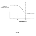
FIG. 3 is a view showing a damping characteristic of the shock absorbing device relative to a vibration frequency. -
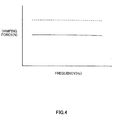
FIG. 4 is a view showing a characteristic of a damping force generated by the shock absorbing device relative to the vibration frequency in a case where the shock absorbing device expands and contracts while a piston speed is at a certain speed within a high speed region. -
FIG. 5 is a view showing a characteristic of a damping force generated by the shock absorbing device relative to the piston speed in a case where the shock absorbing device vibrates at a certain vibration frequency. -
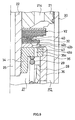
FIG. 6 is a partially enlarged longitudinal sectional view of a specific shock absorbing device. -
FIG. 7 is a partially enlarged longitudinal sectional view showing a first modified example of the specific shock absorbing device. -
FIG. 8 is a partially enlarged longitudinal sectional view showing a second modified example of the specific shock absorbing device. -
FIG. 9 is a partially enlarged longitudinal sectional view showing a third modified example of the specific shock absorbing device. -
FIG. 10 is a partially enlarged longitudinal sectional view showing a fourth modified example of the specific shock absorbing device. -
FIG. 11 is a partially enlarged longitudinal sectional view showing a fifth modified example of the specific shock absorbing device. -
FIG. 12 is a Bode diagram showing the gain characteristic of the frequency transfer function of the pressure relative to the flow rate in a conventional shock absorbing device. -
FIG. 13 is a view showing the damping characteristic of the conventional shock absorbing device relative to the vibration frequency. - This invention will be described below on the basis of the figures. As shown in
FIG. 1 , a shock absorbing device D according to this invention is constituted by a cylinder 1, apiston 2 that is inserted into the cylinder 1 to be free to slide and serves as a partition wall member that partitions the interior of the cylinder 1 into two operating chambers, namely an upper chamber R1 and a lower chamber R2, apassage 3 that connects the upper chamber R1 and the lower chamber R2, a pressure chamber R3, afree piston 9 that is inserted into the pressure chamber R3 to be free to slide and partitions the pressure chamber R3 into a onechamber 7 that communicates with the lower chamber R2 via a oneside flow passage 5 and an other chamber 8 that communicates with the upper chamber R1 via an otherside flow passage 6, aspring element 10 that generates a biasing force to suppress displacement of thefree piston 9 relative to the pressure chamber R3, abypass flow passage 11 that connects the other chamber 8 and the lower chamber R2, and arelief valve 12 provided in thebypass flow passage 11. The shock absorbing device D is interposed between a vehicle body and an axle of a vehicle to generate a damping force for suppressing vehicle body vibration. - A fluid such as working oil is charged into the upper chamber R1, the lower chamber R2, and the pressure chamber R3, and a
sliding partition wall 13 that separates the lower chamber R2 from an air chamber G by contacting an inner periphery of the cylinder 1 slidingly is provided in the cylinder 1 on a lower side of the figure. - It should be noted that a liquid such as water or an aqueous solution, for example, may be used instead of working oil as the fluid charged into the upper chamber R1, lower chamber R2, and pressure chamber R3.
- Further, the
piston 2 is joined to one end of a piston rod 4 inserted into the cylinder 1 to be free to slide, and the piston rod 4 projects outwardly from an upper end portion of the cylinder 1 in the figure. The interior of the cylinder 1 is maintained in a watertight condition by a seal, not shown in the figure, provided between the piston rod 4 and the cylinder 1. Furthermore, the shock absorbing device D is a so-called single rod type device, and it is therefore necessary to compensate for the volume of the piston rod 4 that enters and exits the cylinder 1 as the shock absorbing device D expands and contracts. However, this volume is compensated for when a volume of air of in the air chamber G expands or contracts as the slidingpartition wall 13 moves in a vertical direction ofFIG. 1 . The shock absorbing device D is set as a single cylinder type device, but instead of providing thesliding partition wall 13 and the air chamber G, a reservoir may be provided on an outer periphery or outside of the cylinder 1 such that the volume of the piston rod 4 is compensated for by the reservoir. Further, the shock absorbing device D may be a double rod type device rather than a single rod type device. - Furthermore, a damping
force generating element 14 such as an orifice or a leaf valve may be provided at a midway point in thepassage 3 to apply resistance to the flow of fluid passing through thepassage 3. The dampingforce generating element 14 is not shown in detail in the figure, but is formed by disposing a conventional orifice in parallel with a conventional leaf valve. Instead of disposing an orifice and a leaf valve in parallel, the dampingforce generating element 14 may be formed by disposing a choke and a leaf valve in parallel, for example, or by employing another constitution. - The pressure chamber R3 is formed from a
hollow portion 15a provided in ahousing 15 that is joined to the bottom of thepiston 2 so as to face the lower chamber R2. Thefree piston 9 is provided in the interior of thehollow portion 15a and contacts a side wall of thehollow portion 15a to be capable of moving through thehollow portion 15a in the vertical direction ofFIG. 1 , and thefree piston 9 partitions thehollow portion 15a into the onechamber 7 on the lower side ofFIG. 1 and the other chamber 8 on the upper side ofFIG. 1 . In other words, thefree piston 9 is inserted into the pressure chamber R3 to be free to slide, and is capable of displacing in the vertical direction ofFIG. 1 relative to the pressure chamber R3. - Further, the
free piston 9 is joined to one end of thespring element 10, another end of which is joined to a lower end portion of thehollow portion 15a forming the pressure chamber R3. Thus, thefree piston 9 is positioned in a predetermined position of the pressure chamber R3 such that when thefree piston 9 displaces relative to the pressure chamber R3 from this positioned position (to be referred to simply as a "neutral position" hereafter), a biasing force that is commensurate with the displacement amount is applied thereto by thespring element 10. It should be noted that the neutral position is a position in which thefree piston 9 is positioned relative to the pressure chamber R3 by thespring element 10, and does not necessarily have to be set at an intermediate vertical direction point of thehollow portion 15a. - The pressure chamber R3 is divided vertically into the one
chamber 7 and the other chamber 8 by thefree piston 9 such that an expansion/ contraction direction of the shock absorbing device D matches a movement direction of thefree piston 9. Therefore, when the entire shock absorbing device D vibrates in the vertical direction ofFIG. 1 , vertical direction vibration is excited in thefree piston 9 relative to the pressure chamber R3. To avoid this vibration, the movement direction of thefree piston 9 may be set as an orthogonal direction to the expansion/contraction direction of the shock absorbing device D, or in other words a left-right direction ofFIG. 1 , such that the onechamber 7 and the other chamber 8 are disposed in a lateral direction ofFIG. 1 . - Further, a
throttle 5a may be provided in the oneside flow passage 5 connecting the lower chamber R2 and the onechamber 7 such that resistance is applied to a flow of fluid passing through thethrottle 5a. - Furthermore, the other
side flow passage 6 connecting the upper chamber R1 and the other chamber 8 opens onto a side portion of the piston rod 4 facing the upper chamber R1 and extends from the upper chamber R1 to the other chamber 8 via thepiston 2 and thehousing 15. - When a movement speed of the
piston 2 relative to the cylinder 1 reaches a high speed during an expansion/contraction stroke of the shock absorbing device D, a differential pressure between the upper chamber R1 and the lower chamber R2 increases, leading to a great increase in the resistance applied by thethrottle 5a in the oneside flow passage 5 to the flow of fluid passing through thethrottle 5a. As a result, resistance to a flow of fluid attempting to move from the onechamber 7 into the lower chamber R2 or from the lower chamber R2 into the onechamber 7 greatly exceeds the resistance to the flow of fluid passing through thepassage 3, and therefore a damping force is substantially controlled by the resistance to the flow of fluid passing through thepassage 3. - Hence, in order to reduce the damping force generated when the movement speed of the
piston 2 relative to the cylinder 1 reaches a high speed, thebypass flow passage 11 connecting the other chamber 8 and the lower chamber R2 is provided in thehousing 15. Further, therelief valve 12, which uses a pressure of the other chamber 8 as a pilot pressure, is provided in thebypass flow passage 11. Therelief valve 12 is constituted by a valve main body 12a, aspring 12b that biases the valve main body 12a in a direction for closing thebypass flow passage 11, and apilot passage 12c that causes the pressure of the other chamber 8 to act on the valve main body 12a in a direction opposing the biasing force of thespring 12b. When the piston speed during expansion of the shock absorbing device D reaches a high speed such that the pressure of the other chamber 8 reaches a predetermined pressure, a force exerted on the valve main body 12a by the pilot pressure overcomes the biasing force of thespring 12b, and as a result, the valve main body 12a moves in a direction for compressing thespring 12b. Accordingly, thebypass flow passage 11 is opened such that the other chamber 8 communicates with the lower chamber R2, and thus the pressure in the other chamber 8 can escape into the lower chamber R2. - Next, an operation of the shock absorbing device D will be described. First, an operation performed when the piston speed during expansion/contraction of the shock absorbing device D is low such that the
relief valve 12 in thebypass flow passage 11 does not open will be described. In this case, when thepiston 2 moves vertically inFIG. 1 relative to the cylinder 1 as the shock absorbing device D expands and contracts, one of the upper chamber R1 and the lower chamber R2 is compressed by thepiston 2 while the other is expanded, and therefore the pressure of the compressed chamber, from among the upper chamber R1 and the lower chamber R2, increases while the pressure of the expanded chamber (the chamber that is increased in volume) from among the upper chamber R1 and the lower chamber R2 decreases simultaneously. As a result, a differential pressure is generated between the two chambers. Accordingly, the fluid on the compressed side of the one chamber R1 and the other chamber R2 moves to the expanded side of the one chamber R1 and the other chamber R2 via thepassage 3 and a flow passage constituted by the otherside flow passage 6, the other chamber 8, the onechamber 7, and the oneside flow passage 5. - Assuming that an input speed of the shock absorbing device D during an expansion stroke is identical upon low frequency input and high frequency input, an operation performed upon low frequency input will be described first. In this case, an input amplitude is large, and therefore a flow rate of the fluid that moves from the upper chamber R1 to the lower chamber R2 in a single period increases. The displacement amount of the
free piston 9 increases substantially in proportion with the flow rate, but since thefree piston 9 is biased by thespring element 10, the biasing force received by thefree piston 9 from thespring element 10 increases as the displacement amount of thefree piston 9 increases, and therefore the pressure in the onechamber 7 of the pressure chamber falls below the pressure of the other chamber 8 correspondingly. When the pressure of the onechamber 7 decreases, a differential pressure between the onechamber 7 and the lower chamber R2 decreases, leading to a reduction in the flow rate through thethrottle 5a. The flow rate of thepassage 3 increases in proportion to the reduction in the flow rate through thethrottle 5a, and therefore the damping force remains large. - Conversely, during high frequency input, the input amplitude is small, and therefore the flow rate of the fluid that moves from the upper chamber R1 to the lower chamber R2 in a single period decreases, leading to a reduction in the displacement of the moving
free piston 9. Accordingly, the biasing force received by thefree piston 9 from thespring element 10 decreases such that the pressure in the onechamber 7 of the pressure chamber becomes substantially equal to the pressure of the other chamber 8. As a result, the differential pressure between the onechamber 7 and the lower chamber R2 remains large, and therefore the flow rate through thethrottle 5a is greater than the flow rate at a low frequency. Hence, the flow rate of thepassage 3 decreases correspondingly, leading to a reduction in the damping force. - Therefore, when the piston speed is low, a frequency-related gain characteristic of a frequency transfer function of the differential pressure relative to the flow rate is identical to that of the conventional example represented by Equation (2), as shown in
FIG. 2 . Further, as shown inFIG. 3 , according to a damping force characteristic of the shock absorbing device D, which expresses the gain of the damping force relative to the vibration frequency, a large damping force can be generated in response to vibration in a low frequency region and the damping force can be reduced in response to vibration in a high frequency region. As a result, variation in the damping force of the shock absorbing device D can be made dependent on the input vibration frequency. - On the other hand, in a situation where sudden large-amplitude vibration is input, such as when the vehicle travels over a projection, the movement speed of the
piston 2 relative to the cylinder 1 increases irrespective of the input vibration frequency, and as a result, the flow rate of the fluid flowing from the upper chamber R1 to the lower chamber R2 increases. Accordingly, the fluid resistance of thethrottle 5a greatly exceeds the fluid resistance of thepassage 3, and therefore the damping force increases to a value set in accordance with the specifications of the dampingforce generating element 14 of thepassage 3. - However, when the shock absorbing device D according to this embodiment performs an expansion operation such that the piston moves upward at a high piston speed, the pressure in the high-pressure upper chamber R1 is transmitted to the other chamber 8, causing the
relief valve 12 to open, and as a result, thebypass flow passage 11 opens such that the upper chamber R1 communicates with the lower chamber R2 via the otherside flow passage 6 and the other chamber 8. - Accordingly, the fluid moves from the upper chamber R1 to the lower chamber R2 not only through the
passage 3, but also through a flow passage formed from the otherside flow passage 6, the other chamber 8, and thebypass flow passage 11, and therefore an expansion side damping force generated by the shock absorbing device D can be reduced. -
FIGs. 4 and5 are views showing damping force characteristics of the shock absorbing device, in which dotted lines indicate the damping characteristic of a conventional shock absorbing device and solid lines indicate the damping characteristic of the shock absorbing device D according to this embodiment. As shown inFIGs. 4 and5 , in a situation where the piston speed increases, for example when the vehicle travels over a projection, in the shock absorbing device D according to this embodiment, a gradient of the damping force relative to the piston speed can be reduced, and therefore the damping force can be reduced reliably. Hence, in contrast to the conventional shock absorbing device, in which the damping force remains high such that vibration transfer from the axle to the vehicle body cannot be suppressed favorably, an improvement in the passenger comfort of the vehicle can be achieved. With respect to vibration input in the low frequency region shown inFIG. 5 , a damping characteristic generated in a very low piston speed region is set to rise when the fluid passes through the orifice of the dampingforce generating element 14 in thepassage 3 preferentially, and the reason why an inflection point appears in the damping characteristic at a midway point in the low piston speed region is that when the leaf valve opens, a characteristic generated by the leaf valve becomes dominant. - Further, when the piston speed is in the very low speed region and the low speed region under vibration input in a high frequency region, a lower damping characteristic than the damping characteristic obtained under vibration input in the low frequency region, shown by the dotted line in
FIG. 5 , is obtained, and therefore a damping force of an appropriate magnitude corresponding to the frequency can be generated. By setting the value of a crossover frequency Fa, which is the smaller of crossover frequency values of a damping characteristic shown inFIG. 3 , at or above the value of an above-spring resonance frequency of the vehicle and at or below the value of a below-spring resonance frequency of the vehicle, and setting the value of a crossover frequency Fb, which is the larger of the values, at or below the below-spring resonance frequency of the vehicle, the shock absorbing device D can generate a high damping force in response to vibration input at the above-spring resonance frequency, thereby stabilizing the attitude of the vehicle such that when the vehicle turns, passengers are prevented from feeling anxious. Moreover, a low damping force is invariably generated when vibration is input at the below-spring resonance frequency, and therefore the transfer of axle side vibration to the vehicle body side can be suppressed, enabling an improvement in the passenger comfort of the vehicle. - The damping force at a high piston speed may also be reduced by reducing the resistance of the damping
force generating element 14 in thepassage 3, but in so doing, the damping force that is generated in response to vibration in the low frequency region at a low piston speed decreases, and therefore the damping force may be insufficient, causing the passengers to feel anxious when the vehicle turns. With the shock absorbing device D according to this embodiment, on the other hand, the damping force generated at a high piston speed can be reduced without reducing the resistance of the dampingforce generating element 14 in thepassage 3, and therefore this problem does not occur. - It should be noted that in this embodiment, the piston speed is compartmentalized into a low speed and a high speed for convenience to describe an operation of the
relief valve 12, but the respective boundary speeds of these compartments may be set arbitrarily. Further, the piston speed at which therelief valve 12 opens, or in other words the piston speed forming the boundary between the low speed and the high speed, is preferably set at a piston speed at which a frequency dependence of the damping force disappears or a slightly higher speed than this piston speed. Furthermore, as a specific example of an operation to set a valve opening pressure of the relief valve, the piston speed at which the frequency dependence of the damping force disappears may be learned in advance, whereupon the valve opening pressure of therelief valve 12 is adjusted such that when thepiston 2 displaces relative to the cylinder 1 at the learned piston speed, therelief valve 12 is opened using the internal pressure of the other chamber 8 as the pilot pressure, thereby opening thebypass flow passage 11. - Furthermore, in this embodiment, the other chamber 8, which increases in pressure when the shock absorbing device D expands, is connected to the lower chamber R2 by the
bypass flow passage 11, and therelief valve 12 opens using the pressure of the other chamber 8 as the pilot pressure, and as a result, a reduction in damping force during the expansion operation of the shock absorbing device D is realized. Instead, however, therelief valve 12 may be provided in an opposite orientation to the orientation shown inFIG. 1 such that therelief valve 12 opens using the pressure of the lower chamber R2 as the pilot pressure. In this case, when piston speed is high as the shock absorbing device D contracts, therelief valve 12 is opened such that the pressure of the lower chamber R2 can escape into the upper chamber R1 via thebypass flow passage 11, and thus a reduction in damping force can be achieved during a contraction stroke of the shock absorbing device D. - Furthermore, the
bypass flow passage 11 may be provided to connect the onechamber 7 to the upper chamber R1 such that therelief valve 12 opens using the pressure of the onechamber 7 as the pilot pressure, and a throttle may be provided in the otherside flow passage 6 instead of the oneside flow passage 5. Thus, when piston speed is high as the shock absorbing device D contracts, therelief valve 12 is opened such that the pressure of the lower chamber R2 can escape into the upper chamber R1 via thebypass flow passage 11, and as a result, a reduction in damping force can be achieved during the contraction stroke of the shock absorbing device D. Moreover, in a case where the onechamber 7 is connected to the upper chamber R1 by thebypass flow passage 11, as described above, a reduction in damping force can be achieved during the expansion stroke of the shock absorbing device D by orienting therelief valve 12 oppositely. - Furthermore, in addition to connecting the other chamber 8 and the lower chamber R2 via the
bypass flow passage 11, the onechamber 7 and the upper chamber R1 are connected via a separate, independent bypass flow passage. Further, a relief valve is provided in this independent bypass flow passage. Therefore, a reduction in damping force can be achieved during both the expansion stroke and the contraction stroke of the shock absorbing device D. - It should be noted that in the shock absorbing device D described above, the pressure chamber is formed inside the cylinder, but the pressure chamber may be provided on the outside of the cylinder.
- An outline of the shock absorbing device D was described above. Below, the specific constitution of the shock absorbing device D will be described.
- Specifically, as shown in
FIG. 6 , the shock absorbing device D is constituted by acylinder 20, apiston 21 that is inserted into thecylinder 20 to be free to slide and serves as a partition wall member partitioning the interior of thecylinder 20 into two operating chambers, namely the upper chamber R1 and the lower chamber R2, apiston rod 22 connected to thepiston 21 at one end,passages piston 21 to connect the upper chamber R1 and the lower chamber R2, ahousing 23 that is fixed to a tip end of thepiston rod 22 to form the pressure chamber R3, afree piston 28 that is inserted into thehousing 23 to be free to slide and partitions the pressure chamber R3 into a onechamber 26 that communicates with the lower chamber R2 via a oneside flow passage 24 and aother chamber 27 that communicates with the upper chamber R1 via a otherside flow passage 25, a pair of coil springs 29, 30 accommodated in the onechamber 26 and theother chamber 27, respectively, to serve as spring elements that elastically support thefree piston 28 from either side, abypass flow passage 31 that connects theother chamber 27 and the lower chamber R2, and arelief valve 32 provided in thebypass flow passage 31. Although not shown in the figure, a sliding partition wall is provided below thecylinder 20 to form an air chamber, similarly to the shock absorbing device D shown inFIG. 1 . - Each portion will now be described in detail. In the
piston rod 22, asmall diameter portion 22a is formed on a lower end side inFIG. 6 and ascrew portion 22b is formed on a tip end side of thesmall diameter portion 22a. - The other
side flow passage 25 is formed in thepiston rod 22 so as to open onto the tip end of thesmall diameter portion 22a, pass through the interior of thepiston rod 22, and exit onto a side portion of thepiston rod 22. Although not shown in the figure, a valve such as a throttle that serves as resistance may be provided at a midway point in the otherside flow passage 25. - The
piston 21 is formed in an annular shape, and thesmall diameter portion 22a of thepiston rod 22 is inserted into an inner peripheral side thereof. Thepassages piston 21 such that an upper end of thepassage 21a inFIG. 6 is closed by a laminated leaf valve V1 serving as a damping force generating element and a lower end of theother passage 21b inFIG. 6 is closed by a laminated leaf valve V2 serving as a damping force generating element. - The laminated leaf valves V1, V2 are both formed in an annular shape, and the
small diameter portion 22a of thepiston rod 22 is inserted into an inner peripheral side thereof. The laminated valves V1, V2 are laminated onto thepiston 21 together with anannular valve stopper 33 that limits a deformation amount of the laminated leaf valve V1. - When the shock absorbing device D contracts, the laminated leaf valve V1 is deformed by the differential pressure between the lower chamber R2 and the upper chamber R1. As a result, the laminated leaf valve V1 opens, thereby opening the
passage 21a such that resistance is applied to the flow of liquid moving from the lower chamber R2 to the upper chamber R1. When the shock absorbing device D expands, thepassage 21a is closed. Meanwhile, in contrast to the laminated leaf valve V1, the laminated leaf valve V2 opens thepassage 21b when the shock absorbing device D expands and closes thepassage 21b when the shock absorbing device D contracts. In other words, the laminated leaf valve V1 is a damping force generating element that generates a contraction side damping force when the shock absorbing device D contracts, and the laminated leaf valve V2 is a damping force generating element that generates an expansion side damping force when the shock absorbing device D expands. Further, when thepassages - Hence, when a one-way system is to be employed, as shown in the figure, the
passages passages passages - The
relief valve 32 is laminated onto thescrew portion 22b of thepiston rod 22 from the bottom of the laminated leaf valve V2, and thehousing 23 forming the pressure chamber R3 is screwed to thescrew portion 22b. By means of thehousing 23, thepiston 21, the laminated leaf valves V1, V2, thevalve stopper 33, and therelief valve 32 are fixed to thepiston rod 22. Hence, thehousing 23 serves not only to form the pressure chamber R3 in its interior, but also to fix thepiston 21 to thepiston rod 22. - The
housing 23 will now be described. Thehousing 23 is constituted by aninner tube 34 having acollar 35 that is screwed to thescrew portion 22b of thepiston rod 22, and anouter tube 36 having a closed-end tubular shape. An upper end opening portion of theouter tube 36 inFIG. 6 is attached to an outer periphery of thecollar 35 by being swaged against the outer periphery of thecollar 35, and as a result, theouter tube 36 and theinner tube 34 are integrated such that the pressure chamber R3 is defined in the lower chamber R2 by theinner tube 34 and theouter tube 36. When integrating theinner tube 34 and theouter tube 36, a method such as welding may be employed instead of the swaging method described above. - The
free piston 28 is inserted into the pressure chamber R3, formed as described above, to be free to slide, whereby the pressure chamber R3 is partitioned into the upper sideother chamber 27 and the lower side onechamber 26 inFIG. 6 . - Further, the
inner tube 34 includes theaforementioned collar 35, and ascrew portion 34a is formed on an inner periphery of theinner tube 34 such that by screwing thescrew portion 34a to thescrew portion 22b of thepiston rod 22, thehousing 23 can be fixed to thesmall diameter portion 22a of thepiston rod 22. Accordingly, an operation for screwing thehousing 23 to the tip end of thepiston rod 22 can be performed more easily by forming the outer periphery of theouter tube 36 with a sectional shape such as a partially cut away shape or a hexagonal shape rather than a perfectly circular shape. - Further, the
collar 35 of theinner tube 34 is provided with a plurality ofports 35a that open onto a lower end thereof inFIG. 6 , and anannular window 35b that opens onto an upper end thereof inFIG. 6 and communicates with theports 35a. Theports 35a and thewindow 35b penetrate thecollar 35, thereby forming thebypass flow passage 31 that connects theother chamber 27 to the lower chamber R2. It should be noted that thewindow 35b need not be provided, and instead, theports 35a may be opened onto the upper end of thecollar 35 inFIG. 6 . - The
window 35b is opened and closed by therelief valve 32, which is laminated onto the upper end of thecollar 35 inFIG. 6 , i.e. an operating chamber side of thecollar 35. Specifically, therelief valve 32 is constituted by a leaf valve formed from a plurality of laminated annular plates. - A
spacer 40 which is thicker and has a smaller outer diameter than therelief valve 32 and the laminated leaf valve V2 laminated onto the bottom of thepiston 21 is interposed between therelief valve 32 and the laminated leaf valve V2 to prevent interference therebetween when the outer periphery of the laminated leaf valve V2 deforms downward while the outer periphery of therelief valve 32 deforms upward. - Further, an outer peripheral side of the
collar 35 beyond thewindow 35b extends further upward inFIG. 6 than an inner peripheral side such that when the outer periphery of therelief valve 32 formed from a leaf valve deforms upward inFIG. 6 , an initial load is applied to therelief valve 32. Accordingly, therelief valve 32 continues to close thebypass flow passage 31 until a force generated by the differential pressure between theother chamber 27 and the lower chamber R2 for deforming therelief valve 32 upward inFIG. 6 overcomes the initial load, and when the differential pressure between theother chamber 27 and the lower chamber R2 reaches a valve opening pressure, the outer periphery of therelief valve 32 deforms further upward inFIG. 6 , thereby separating from thecollar 35 such that thebypass flow passage 31 opens and theother chamber 27 communicates with the lower chamber R2. In other words, therelief valve 32 opens using the pressure of theother chamber 27 as a pilot pressure, and therefore functions as a pressure chamber side relief valve. - A lower end of the
outer tube 36 inFIG. 6 is reduced in diameter such that astep portion 36b is formed in atube portion 36a, and a fixedorifice 37 constituting a part of the oneside flow passage 24 is provided in abottom portion 36c of theouter tube 36. - The
free piston 28, which is inserted into the pressure chamber R3 formed by theinner tube 34 and theouter tube 36 as described above, is formed in a closed-end tubular shape and includes atube portion 28a, a bottom portion 28b that closes one end of thetube portion 28a, a projectingportion 28c provided on a lower end of the bottom portion 28b inFIG. 6 so as to project toward thebottom portion 36c of theouter tube 36, and anannular groove 28d formed in an outer periphery of thetube portion 28a. An inner side of thefree piston 28 faces theinner tube 34, and thetube portion 28a contacts the inner periphery of theouter tube 36 slidingly, thereby partitioning the pressure chamber R3 into the onechamber 7 and the other chamber 8. - Further, the coil springs 29, 30 serving as spring elements are interposed, respectively, in the
other chamber 27 between thecollar 35 of theinner tube 34 and the bottom portion 28b inner side of thefree piston 28 and in the onechamber 26 between thebottom portion 36c of theouter tube 36 and the bottom portion 28b outer side of thefree piston 28. As a result, thefree piston 28 is sandwiched between the coil springs 29, 30 from top and bottom and elastically supported so as to be positioned in a predetermined neutral position within the pressure chamber R3. Thus, a biasing force is applied to thefree piston 28 in proportion to a displacement amount thereof relative to thehousing 23, whereby displacement of thefree piston 28 is suppressed. - It should be noted that as long as the
free piston 28 can be elastically supported, a member other than the coil springs 29, 30 may be employed as the spring element. For example, an elastic body such as a plate spring may be used to provide elastic support to thefree piston 28. Further, when a single spring element joined at one end to thefree piston 28 is used, the other end thereof may be fixed to theinner tube 34 or theouter tube 36. - A lower end of the
coil spring 29 inFIG. 6 is positioned in a radial direction by being fitted into an inner periphery of a deepest part of thebottom portion 28a of thefree piston 28, and thecoil spring 30 is centered by inserting the projectingportion 28c of thefree piston 28 into an inner periphery of thecoil spring 30. Thus, positional deviation of the coil springs 29, 30 relative to thefree piston 28 can be prevented, and the biasing force can be applied to thefree piston 28 with stability. - The inner periphery of the
tube portion 28a of thefree piston 28 has a larger diameter than the deepest portion, and therefore a wire of thecoil spring 29 does not touch the inner periphery of thetube portion 28a when thecoil spring 29 is compressed such that a coil diameter thereof increases. As a result, contamination in prevented. - Further, the projecting
portion 28c functions to center thecoil spring 30, as described above, and a height (vertical direction length inFIG, 6 ) of the projectingportion 28c is set at a sufficient height to prevent lifting of the coil spring 30 (separation of thecoil spring 30 from the projectingportion 28c). - In addition to the constitution described above, the
free piston 28 according to this embodiment includes ahole 28e that passes through the interior of thetube portion 28a and bottom portion 28b of thefree piston 28 to connect theannular groove 28d and the onechamber 26. - Further, two
variable orifices tube portion 36a of theouter tube 36 to connect the lower chamber R2 to the interior of theouter tube 36, and whenever thefree piston 28 is in the neutral position under the elastic support of the coil springs 29, 30, thevariable orifices annular groove 28d so as to connect the onechamber 26 and the lower chamber R2. Further, when thefree piston 28 displaces to a stroke end at a lower end of theinner tube 34 inFIG. 6 , or in other words when thefree piston 28 displaces until it comes into contact with thestep portion 36b of theouter tube 36, thevariable orifices tube portion 28a of thefree piston 28 and thereby closed. Hence, the oneside flow passage 24 is constituted by theannular groove 28d, thevariable orifices hole 28e, and the fixedorifice 37. It should be noted that although twovariable orifices - Hence, in the shock absorbing device D described above, when the displacement amount of the
free piston 28 from the neutral position reaches an arbitrary displacement amount, thevariable orifices annular groove 28d toward a state of opposing the outer periphery of thetube portion 28a, whereby a flow passage sectional area of thevariable orifices side flow passage 24 gradually increases. The aforementioned arbitrary displacement amount is set in accordance with a vertical direction width of theannular groove 28d inFIG. 6 and an opening position of thevariable orifices outer tube 36 inner periphery side. As the displacement amount of thefree piston 28 increases, the flow passage sectional area of thevariable orifices free piston 28 reaches the stroke end, thevariable orifices tube portion 28a and are closed thereby. As a result, the flow passage resistance in the oneside flow passage 24 reaches a maximum, whereby the onechamber 26 communicates with the lower chamber R2 via the fixedorifice 37 alone. - Operations of the shock absorbing device D having the above constitution will now be described.
- (A) Operation of shock absorbing device D when displacement amount of
free piston 28 from neutral position is within range in whichvariable orifices relief valve 32 does not open - In this case, the piston speed is low and the differential pressure between the
other chamber 27 and the lower chamber R2 has not reached the valve opening pressure of therelief valve 32, and therefore thefree piston 28 can displace without varying the resistance of the oneside flow passage 24. - Considering a case in which the input speed of the shock absorbing device D remains constant while the input frequency is either low or high, when the input frequency is low, the input amplitude increases, and therefore the amplitude of the
free piston 28 increases within the range in which thevariable orifices - When the amplitude of the
free piston 28 increases within this range, the biasing force received by thefree piston 28 from the coil springs 29, 30 increases, and as a result, the internal pressure of the onechamber 26 falls below the internal pressure of theother chamber 27 by an amount corresponding to the biasing force of the coil springs 29, 30. - Accordingly, the differential pressure between the one
chamber 26 and the lower chamber R2 decreases, leading to a reduction in the flow rate through the oneside flow passage 24. - Conversely, when the input frequency input into the shock absorbing device D is high, the input amplitude decreases, and therefore the amplitude of the
free piston 28 decreases. When the amplitude of thefree piston 28 decreases, the biasing force received by thefree piston 28 from the coil springs 29, 30 decreases, and as a result, the internal pressure of the onechamber 26 becomes substantially equal to the internal pressure of theother chamber 27. Accordingly, the differential pressure between the onechamber 26 and the lower chamber R2 remains large, whereby the flow rate through the oneside flow passage 24 also remains large. - In other words, when the input frequency input into the shock absorbing device D is low, the flow rate through the one
side flow passage 24 is small, and when the input frequency is high, the flow rate through the oneside flow passage 24 increases. If the input speed is constant, the flow rate from the upper chamber R1 to the lower chamber R2 must remain constant regardless of the input frequency, and therefore the flow rate through the laminated leaf valves V1, V2 in thepassages FIG. 3 , according to the damping characteristic of the shock absorbing device D, the damping force is high when the input frequency is low and low when the input frequency is high. - (B) Operation of shock absorbing device D when displacement amount of
free piston 28 from neutral position is within range in which bothvariable orifices side flow passage 24, butrelief valve 32 does not open - In this case also, the piston speed is low and the differential pressure between the
other chamber 27 and the lower chamber R2 has not reached the valve opening pressure of therelief valve 32, and therefore thefree piston 28 displaces relative to thehousing 23. - When the
variable orifices free piston 28, the flow passage sectional area gradually decreases, and when thefree piston 28 reaches the stroke end, thevariable orifices orifice 37. - In other words, once the
free piston 28 begins to close thevariable orifices side flow passage 24 gradually increases in accordance with the displacement amount, and when thefree piston 28 reaches the stroke end, the flow passage resistance reaches a maximum. - Here, the
free piston 28 displaces to the stroke end when the amount of liquid flowing into or out of the onechamber 26 or theother chamber 27 is large, or more specifically when the amplitude of the vibration in the shock absorbing device D is large. - When the vibration frequency of the shock absorbing device D is comparatively high, the shock absorbing device D generates a comparatively low damping force until the
free piston 28 displaces to a position in which thevariable orifices free piston 28 displaces beyond the position in which thevariable orifices side flow passage 24 gradually increases. As a result, a movement speed of thefree piston 28 toward the stroke end side decreases, the amount of liquid moving between the upper chamber R1 and the lower chamber R2 via the pressure chamber R3 decreases, and the amount of liquid passing through thepassages - When the
free piston 28 reaches the stroke end, liquid movement between the upper chamber R1 and the lower chamber R2 via the pressure chamber R3 stops such that the liquid passes through only thepassages - More specifically, even when high-frequency, large-amplitude vibration that causes the
free piston 28 to displace to the stroke end is input into the shock absorbing device D, the damping force generated by the shock absorbing device D increases gradually from the point at which the displacement amount of thefree piston 28 from the neutral position exceeds the arbitrary displacement amount to the point at which thefree piston 28 reaches the stroke end, and therefore situations in which a low damping force varies rapidly to a high damping force are eliminated. In other words, rapid variation in the magnitude of the damping force does not occur when thefree piston 28 reaches the stroke end such that liquid movement between the upper chamber R1 and the lower chamber R2 via the pressure chamber R3 stops, and therefore damping force variation from a low damping force to a high damping force occurs smoothly. Moreover, when thefree piston 28 reaches the stroke end on either end side of the pressure chamber R3, the generated damping force increases gradually, and therefore rapid damping force variation can be suppressed during both the expansion stroke and the contraction stroke of the shock absorbing device D. - Hence, according to the shock absorbing device D, the generated damping force varies smoothly even when high-frequency, large-amplitude vibration is input, and therefore passengers do not experience shock due to damping force variation. Accordingly, an improvement in the passenger comfort of the vehicle can be achieved. In particular, situations in which the vehicle body vibrates due to rapid damping force variation, causing the engine hood to resonate such that noise is generated, can be prevented, and in this regard also, an improvement in the passenger comfort of the vehicle can be achieved.
- As described above in (A) and (B), when the piston speed is high but the flow passage resistance through the fixed
orifice 37 and thevariable orifices free piston 28 displaces to the stroke end, the damping force increases gradually, and therefore damping force variation in which a decreasing damping force suddenly increases can be suppressed. - When the piston speed is high and the flow passage resistance through the fixed
orifice 37 and thevariable orifices other chamber 27 communicating with the compressed upper chamber R1 via the otherside flow passage 25 increases such that the outer periphery of therelief valve 32 deforms so as to overcome the initial load, and as a result, thebypass flow passage 31 constituted by theports 35a and thewindow 35b provided in thecollar 35 opens. - Hence, the liquid moves from the upper chamber R1 to the lower chamber R2 not only through the
passage 21b but also through the otherside flow passage 25, theother chamber 27, and thebypass flow passage 31, enabling a reduction in the expansion side damping force generated by the shock absorbing device D. - Thus, with the shock absorbing device D according to this embodiment, in a situation where the piston speed increases, for example when the vehicle travels over a projection, the damping force gradient relative to the piston speed can be reduced, as shown by the solid lines in
FIGs. 4 and5 , in contrast to the damping characteristic of the conventional shock absorbing device shown by the dotted lines inFIGs. 4 and5 , and as a result, the damping force can be reduced reliably. Therefore, in contrast to the conventional shock absorbing device, in which the damping force remains high such that vibration transfer from the axle to the vehicle body cannot be suppressed favorably, an improvement in the passenger comfort of the vehicle can be achieved. - Further, in the shock absorbing device D according to this embodiment, the pressure chamber R3 is provided in the
housing 23 which is disposed inside the lower chamber R2 serving as one of the operating chambers and fixes thepiston 21, which serves as a partition wall member fitted to thepiston rod 22, to thepiston rod 22 by being screwed to thepiston rod 22 inserted into the cylinder 1. Further, thebypass flow passage 31 communicates with theother chamber 27 and the lower chamber R2 serving as one of the operating chambers. Hence, thehousing 23 also functions as a piston nut, thereby facilitating formation of the pressure chamber R3 in the lower chamber R2 serving as one of the operating chambers, and disposal of thebypass flow passage 31 is also facilitated. - Moreover, the
housing 23 comprises theinner tube 34 having thecollar 35, and the closed-end tube shapedouter tube 36 attached to the outer periphery of thecollar 35, and therefore the pressure chamber R3 can be formed while establishing the piston nut function through a simple structure. - Furthermore, the
bypass flow passage 31 penetrates thecollar 35 of theinner tube 34 to communicate with theother chamber 27 and the lower chamber R2 serving as one of the operating chambers, and the pressure chamberside relief valve 32 is formed such that the bypass flow passage is opened and closed by an annular leaf valve that is attached to thepiston rod 22 and laminated to the lower chamber R2 side of thecollar 35 provided on theinner tube 34. Hence, therelief valve 32 can be formed simply by fixing the leaf valve to thepiston rod 22 via thehousing 23. Moreover, since therelief valve 32 is constituted by a leaf valve, an axial direction length of the shock absorbing device D does not increase, and a stroke length thereof is not restricted. - Further, in the shock absorbing device D, the biasing force that returns the
free piston 28 to the neutral position is applied by the coil springs 29, 30, and therefore a situation in which the function for making the damping force dependent on the input frequency cannot be exercised when required does not occur. - Next, referring to
FIG. 7 , a first modified example of the shock absorbing device will be described. The shock absorbing device according to this modified example differs from the shock absorbing device D shown inFIG. 6 in that aspring support 41 is interposed between an upper end serving as one end of thecoil spring 29 accommodated in theother chamber 27 and thecollar 35 of theinner tube 34. Thespring support 41 includes atube portion 41a fitted onto the outer periphery of theinner tube 34 and aspring support portion 41b extending from a lower end outer periphery of thetube portion 41a, an annular gap being provided between the outer periphery of thespring support portion 41b and the inner periphery of theouter tube 36 forming thehousing 23. - By using the
spring support 41 to support the upper end of thecoil spring 29, interference between the upper end of thecoil spring 29 inFIG. 7 and theports 35a provided in thecollar 35, leading to partial or complete closure of theports 35a, can be prevented. Hence, when the shock absorbing device expands and the piston speed is in the high speed region, theother chamber 27 and the lower chamber R2 serving as one of the operating chambers can be connected by thebypass flow passage 31 reliably and with a fixed flow passage sectional area, and therefore the damping force generated by the shock absorbing device can be reduced reliably and the reduced damping force can be stabilized. Furthermore, thecoil spring 29 does not interfere with theports 35a even if the inner diameter of theports 35a is increased, and therefore the gradient of the generated damping force characteristic relative to the piston speed when thebypass flow passage 31 is open can be reduced even further. - Referring to
FIG. 8 , a second modified example of the shock absorbing device will be described. The shock absorbing device according to this modified example differs from the shock absorbing device D shown inFIG. 6 in that an annular interposedmember 42 forming a part of thebypass flow passage 31 is interposed between thecollar 35 of theinner tube 34 forming thehousing 23 and the leaf valve forming therelief valve 32. - The interposed
member 42 is a thick disc-shaped member having holes, in which a plurality ofports 42a open downward inFIG. 8 andannular windows 42b communicating respectively with the plurality ofports 42a are provided above theports 42a inFIG. 8 . - Further, the
collar 35 of theinner tube 34 is provided with a throughhole 35c penetrating thecollar 35 in place of the ports and window such that when the interposedmember 42 is laminated onto theinner tube 34, theports 42a connect theother chamber 27 in thehousing 23 to the lower chamber R2 serving as one of the operating chambers via the throughhole 35c in thecollar 35. In other words, in the shock absorbing device according to the second modified example, thebypass flow passage 31 is constituted by the throughhole 35c provided in thecollar 35, theports 42a andwindows 42b of the interposedmember 42. - It should be noted that the interposed
member 42 may be laminated to thecollar 35 including theports 35a and thewindow 35b. In this case, theports 42a can be connected to thewindow 35b reliably without positioning theinner tube 34 and the interposedmember 42 in the circumferential direction, enabling an increase in convenience. - The interposed
member 42 is provided with theports 42a forming a part of thebypass flow passage 31, and therefore, by preparing interposedmembers 42 having differently shaped andsized ports 42a in advance and replacing the interposedmember 42, the damping characteristic generated when therelief valve 32 opens thebypass flow passage 31 can be adjusted. - Further, as shown by a third modified example in
FIG. 9 , by providing anannular seat portion 42c on/from which therelief valve 32 sits/separates on the outer periphery of thewindow 42b in the interposedmember 42 and preparing interposedmembers 42 havingseat portions 42c of different heights in a vertical direction ofFIG. 9 , the height of theseat portion 42c can be modified by replacing the interposedmember 42, and as a result, the initial load applied to therelief valve 32 can be modified. Thus, the valve opening pressure of therelief valve 32 can be adjusted. - As described above, to apply the initial load determining the valve opening pressure to the
relief valve 32, theentire relief valve 32 may be deformed in advance by causing a support position of the inner periphery serving as a fixed end and a support position in which the outer periphery serving as a free end closes thebypass flow passage 31 to deviate from each other in the axial direction. Alternatively, as shown by a fourth modified example inFIG. 10 , the valve opening pressure of therelief valve 32 may be set by interposing aring 43 between arbitrary annular plates of the leaf valve forming therelief valve 32 such that initial deformation is applied to the annular plates laminated to the upper side ofFIG. 10 by thering 43. In this case, the valve opening pressure can be modified by adjusting a plate thickness of thering 43. - Finally, referring to
FIG. 11 , a fifth modified example of the shock absorbing device will be described. The shock absorbing device according to this modified example differs from the shock absorbing device D shown inFIG. 6 in the constitution of arelief valve 44. - More specifically, the
relief valve 44 is constituted by anannular valve seat 35d that projects from thecollar 35 of theinner tube 34 forming thehousing 23 toward an end portion of thecollar 35 on the side of the lower chamber R2 serving as one of the operating chambers, a small-diameter spacer 45 interposed between theinner tube 34 and the laminated leaf valve V2, an annularvalve seat member 46 having a larger outer diameter than thespacer 45, and anannular leaf valve 47 that is ring shaped and has an inner peripheral upper surface which sits on a lower end of thevalve seat member 46 and an outer peripheral lower surface which sits on an upper end of thevalve seat 35d. - Further, in this shock absorbing device, the
collar 35 is provided withonly ports 35e and no windows such that thebypass flow passage 31 is constituted by theports 35e connecting theother chamber 27 to the lower chamber R2 serving as one of the operating chambers. - When the pressure of the
other chamber 27 exceeds the pressure of the lower chamber R2 such that the differential pressure therebetween reaches the valve opening pressure, the outer peripheral side of theleaf valve 47 is deformed toward the upper side inFIG. 11 by the pressure of theother chamber 27, and as a result, theleaf valve 47 separates from thevalve seat 35d, thereby opening thebypass flow passage 31 such that the pressure of the upper chamber R1 escapes into the lower chamber R2 via theother chamber 27. Thus, therelief valve 44 functions as a pressure chamber side relief valve. Conversely, when the pressure of the lower chamber R2 exceeds the pressure of theother chamber 27 such that the differential pressure therebetween reaches the valve opening pressure, the inner peripheral side of theleaf valve 47 is deformed toward the lower side inFIG. 11 by the pressure of the lower chamber R2, and as a result, theleaf valve 47 separates from thevalve seat member 46, thereby opening thebypass flow passage 31 such that the pressure of the lower chamber R2 escapes into the upper chamber R1 via theother chamber 27. Thus, therelief valve 44 functions as an operating chamber side relief valve. In other words, theleaf valve 47 is set to open both inwardly and outwardly. - With the
relief valve 44 constituted in this manner, thebypass flow passage 31 is opened by the internal pressure of theother chamber 27 when the piston speed is high during the expansion stroke of the shock absorbing device, and therefore the damping force generated during expansion of the shock absorbing device can be reduced. When the piston speed is high during the contraction stroke of the shock absorbing device, on the other hand, thebypass flow passage 31 is opened by the internal pressure of the lower chamber R2, and therefore the damping force generated during contraction of the shock absorbing device can be reduced. In other words, therelief valve 44 is capable of reducing the damping force on both the expansion side and the contraction side when the piston speed is high. - Further, the
relief valve 44 employs theleaf valve 47 that opens both inwardly and outwardly, and therefore the damping force generated by the shock absorbing device on both the expansion side and the contraction side can be reduced by a single leaf valve, i.e. without employing a constitution in which two bypass flow passages are provided and a single-direction relief valve is provided in each. As a result, reductions in cost and the number of components can be achieved. - An embodiment of this invention was described above, but the above embodiment is merely an example of application of the invention, and the technical scope of this invention is not limited to the specific constitutions of the above embodiment.
- This application claims priority based on Japanese Patent Application
2009-012657
Claims (9)
- A shock absorbing device (D) comprising:a cylinder (1, 20);a partition wall member (2, 21) that is inserted into the cylinder (1, 20) to be free to slide and partitions an interior of the cylinder (1, 20) into two operating chambers (R1,R2);a passage (3, 21a, 21b) that connects the two operating chambers (R1, R2);a pressure chamber (R3);a free piston (9, 28) that is inserted into the pressure chamber (R3) to be free to slide and partitions the pressure chamber (R3) into a one chamber (7, 26) that communicates with one operating chamber (R2) via a one side flow passage (5, 24) and an other chamber (8, 27) that communicates with the other operating chamber (R1) via an other side flow passage (6, 25); anda spring element (10, 29, 30) that generates a biasing force for suppressing displacement of the free piston (9, 28) relative to the pressure chamber (R3),wherein one or both of a bypass flow passage (11, 31) that connects the other chamber (8, 27) and the one operating chamber (R2) and a bypass flow passage that connects the one chamber (7, 26) and the other operating chamber (R1) is provided, and a relief valve (12, 32) is provided in the bypass flow passage (11, 31).
- The shock absorbing device (D) as defined in Claim 1, wherein an operating chamber (R2) side relief valve that uses a pressure of the operating chamber (R2) connected to the bypass flow passage (11, 31), from among the two operating chambers (R1, R2), as a pilot pressure and a pressure chamber (R3) side relief valve (12, 32) that uses a pressure of the chamber (8, 27) connected to the bypass flow passage (11, 31), from among the one chamber (7, 26) and the other chamber (8, 27), as a pilot pressure are provided in the bypass flow passage (11, 31) in parallel.
- The shock absorbing device (D) as defined in Claim 1, wherein the pressure chamber (R3) is provided inside a housing (15, 23) that is disposed in the one operating chamber (R2) and screwed to a piston rod (4, 22) inserted into the cylinder (1, 20) such that the partition wall member (2, 21) fitted onto the piston rod (4, 22) is fixed to the piston rod (4, 22), and
the bypass flow passage (11, 31) connects the other chamber (8, 27) and the one operating chamber (R2). - The shock absorbing device (D) as defined in Claim 3, wherein the housing (15, 23) forms the pressure chamber (R3) by including an inner tube (34) having a collar (35) and a closed-end tubular outer tube (36) attached to an outer periphery of the collar (35),
the free piston (9, 28) contacts an inner periphery of the outer tube (36) slidingly so as to partition the pressure chamber (R3) into the one chamber (7, 26) and the other chamber (8, 27),
the bypass flow passage (11, 31) penetrates the collar (35) on the inner tube (34) to connect the other chamber (8, 27) and the one operating chamber (R2), and the pressure chamber (R3) side relief valve (12, 32) comprises an annular leaf valve which is attached to the piston rod (4, 22) so as to be laminated to the operating chamber (R2) side of the collar (35) on the inner tube (34), whereby the bypass flow passage (11, 31) is opened and closed by the leaf valve. - The shock absorbing device (D) as defined in Claim 4, wherein the leaf valve is formed by laminating a plurality of annular plates, and
a ring (43) is interposed between arbitrary annular plates to apply an initial deformation to the annular plates. - The shock absorbing device (D) as defined in Claim 4, wherein an annular interposed member (42) that forms a part of the bypass flow passage (11, 31) is inserted between the collar (35) on the inner tube (34) and the leaf valve.
- The shock absorbing device (D) as defined in Claim 6, wherein the interposed member (42) is provided with an annular seat portion (42c) on/from which the leaf valve sits/separates and which applies the initial deformation to the leaf valve.
- The shock absorbing device (D) as defined in Claim 4, wherein the leaf valve functions as a pressure chamber (R3) side relief valve (12) that opens the bypass flow passage (11, 31) by deforming an outer periphery of the leaf valve in response to a flow heading toward the one operating chamber (R2) from the other chamber (8, 27), and functions as an operating chamber (R2) side relief valve that opens the bypass flow passage (11, 31) by deforming an inner periphery of the leaf valve in response to a flow heading toward the other chamber (8, 27) from the one operating chamber (R2).
- The shock absorbing device (D) as defined in Claim 4, wherein the spring element (10, 29, 30) comprises a one chamber (7, 26) side spring (30) accommodated in the one chamber (7, 26) and a other chamber (8, 27) side spring (29) accommodated in the other chamber (8, 27),
the free piston (9, 28) is sandwiched between the one chamber (7, 26) side spring (30) and the other chamber (8, 27) side spring (29), and
an annular spring support (41) that supports one end of the other chamber (8, 27) side spring (29) is provided on the outer periphery of the inner tube (34) to prevent blockage of the bypass flow passage (11, 31).
Applications Claiming Priority (2)
| Application Number | Priority Date | Filing Date | Title |
|---|---|---|---|
| JP2009012657A JP5132590B2 (en) | 2009-01-23 | 2009-01-23 | Shock absorber |
| PCT/JP2009/069012 WO2010084658A1 (en) | 2009-01-23 | 2009-10-30 | Buffer device |
Publications (2)
| Publication Number | Publication Date |
|---|---|
| EP2383486A1 true EP2383486A1 (en) | 2011-11-02 |
| EP2383486A4 EP2383486A4 (en) | 2017-05-17 |
Family
ID=42355727
Family Applications (1)
| Application Number | Title | Priority Date | Filing Date |
|---|---|---|---|
| EP09838848.1A Withdrawn EP2383486A4 (en) | 2009-01-23 | 2009-10-30 | Buffer device |
Country Status (6)
| Country | Link |
|---|---|
| US (1) | US9169891B2 (en) |
| EP (1) | EP2383486A4 (en) |
| JP (1) | JP5132590B2 (en) |
| KR (1) | KR101160776B1 (en) |
| CN (1) | CN102016347B (en) |
| WO (1) | WO2010084658A1 (en) |
Cited By (3)
| Publication number | Priority date | Publication date | Assignee | Title |
|---|---|---|---|---|
| WO2014191226A1 (en) * | 2013-05-27 | 2014-12-04 | Thyssenkrupp Bilstein Gmbh | Vibration damper for a vehicle |
| CN104246284A (en) * | 2012-04-27 | 2014-12-24 | 萱场工业株式会社 | Suspension device |
| DE102014210701A1 (en) * | 2014-06-05 | 2015-12-17 | Zf Friedrichshafen Ag | Vibration damper and motor vehicle |
Families Citing this family (42)
| Publication number | Priority date | Publication date | Assignee | Title |
|---|---|---|---|---|
| JP3176746B2 (en) | 1993-02-22 | 2001-06-18 | 日鐵溶接工業株式会社 | Power supply tip for welding |
| US8616351B2 (en) | 2009-10-06 | 2013-12-31 | Tenneco Automotive Operating Company Inc. | Damper with digital valve |
| JP5438487B2 (en) * | 2009-12-11 | 2014-03-12 | カヤバ工業株式会社 | Shock absorber |
| JP5564368B2 (en) * | 2010-08-30 | 2014-07-30 | カヤバ工業株式会社 | Rear cushion unit |
| JP5603817B2 (en) * | 2011-03-23 | 2014-10-08 | カヤバ工業株式会社 | Shock absorber |
| KR101288612B1 (en) | 2011-07-21 | 2013-07-22 | 주식회사 만도 | Valve structure of a shock absorber |
| US9611915B2 (en) * | 2011-07-21 | 2017-04-04 | Mando Corporation | Valve structure of shock absorber |
| WO2013036313A1 (en) | 2011-08-19 | 2013-03-14 | Avery Dennison Corporation | Low noise flexible barrier films |
| JP5851159B2 (en) * | 2011-08-31 | 2016-02-03 | 日立オートモティブシステムズ株式会社 | Shock absorber |
| KR101375804B1 (en) * | 2011-09-02 | 2014-03-21 | 주식회사 만도 | Shock absorber with a frequency and pressure unit |
| NL2007530C2 (en) * | 2011-10-04 | 2013-04-08 | Koni Bv | FREQUENCY-DEPENDENT DAMPER. |
| EP2794266A1 (en) | 2011-12-22 | 2014-10-29 | Avery Dennison Corporation | Flexible barrier films containing cyclic olefins |
| KR101350093B1 (en) | 2012-08-14 | 2014-01-10 | 주식회사 만도 | Piston valve of shock absorber |
| KR101350078B1 (en) | 2012-08-14 | 2014-01-15 | 주식회사 만도 | Piston valve of shock absorber |
| US9217483B2 (en) | 2013-02-28 | 2015-12-22 | Tenneco Automotive Operating Company Inc. | Valve switching controls for adjustable damper |
| US9884533B2 (en) | 2013-02-28 | 2018-02-06 | Tenneco Automotive Operating Company Inc. | Autonomous control damper |
| WO2014134500A1 (en) | 2013-02-28 | 2014-09-04 | Tenneco Automotive Operating Company Inc. | Damper with integrated electronics |
| US9163691B2 (en) | 2013-03-15 | 2015-10-20 | Tenneco Automotive Operating Company Inc. | Rod guide arrangement for electronically controlled valve applications |
| US9879746B2 (en) | 2013-03-15 | 2018-01-30 | Tenneco Automotive Operating Company Inc. | Rod guide system and method with multiple solenoid valve cartridges and multiple pressure regulated valve assemblies |
| EP2971847A4 (en) | 2013-03-15 | 2016-12-21 | Tenneco Automotive Operating Co Inc | Rod guide assembly with multi-piece valve assembly |
| US9879748B2 (en) | 2013-03-15 | 2018-01-30 | Tenneco Automotive Operating Company Inc. | Two position valve with face seal and pressure relief port |
| CN103216494A (en) * | 2013-04-25 | 2013-07-24 | 长沙理工大学 | Air chamber and spring combined buffering slow-release cavity arranged in hinged pin shaft |
| CN103216490A (en) * | 2013-04-25 | 2013-07-24 | 长沙理工大学 | Air bag type buffering slow-release cavity arranged at end of hinged pin shaft |
| JP6108550B2 (en) * | 2013-09-19 | 2017-04-05 | Kyb株式会社 | Shock absorber |
| JP6243173B2 (en) * | 2013-09-20 | 2017-12-06 | Kyb株式会社 | Shock absorber |
| JP6274798B2 (en) * | 2013-09-20 | 2018-02-07 | Kyb株式会社 | Shock absorber |
| JP6160829B2 (en) * | 2013-12-05 | 2017-07-12 | 株式会社アドヴィックス | Electric braking device for vehicle |
| CN103758914A (en) * | 2013-12-25 | 2014-04-30 | 山河智能装备股份有限公司 | Buffering oil cylinder of dynamic compaction machine and installation structure thereof |
| US20170267700A1 (en) * | 2014-08-27 | 2017-09-21 | University Of Florida Research Foundation, Inc. | Precursors for Electron Beam-Induced Deposition of Gold and Silver |
| CN106218343B (en) * | 2016-08-23 | 2019-01-25 | 北汽福田汽车股份有限公司 | For the control method of electromagnetic suspension, device and vehicle |
| NO20162042A1 (en) * | 2016-12-22 | 2018-06-25 | Vetco Gray Scandinavia As | Shock absorbing damper |
| US10479160B2 (en) | 2017-06-06 | 2019-11-19 | Tenneco Automotive Operating Company Inc. | Damper with printed circuit board carrier |
| US10588233B2 (en) | 2017-06-06 | 2020-03-10 | Tenneco Automotive Operating Company Inc. | Damper with printed circuit board carrier |
| CN108087622B (en) * | 2017-11-28 | 2019-07-05 | 安徽荣达阀门有限公司 | A hydraulic buffer device for valve |
| US10570983B2 (en) | 2018-03-23 | 2020-02-25 | Tenneco Automotive Operating Company Inc. | Damper with floating piston bleed channel |
| US10663027B2 (en) * | 2018-03-23 | 2020-05-26 | Tenneco Automotive Operating Company Inc. | Damper with valve preload limiter |
| KR102368548B1 (en) * | 2018-06-18 | 2022-03-02 | 박기혁 | Safety apparatus for cultivator |
| WO2019245231A1 (en) * | 2018-06-18 | 2019-12-26 | 박기혁 | Safety device for tiller |
| US10907700B2 (en) * | 2018-12-04 | 2021-02-02 | Truman R. Davis | Torque impact mitigator for power tong |
| CN112356924B (en) * | 2020-10-26 | 2022-08-23 | 东风越野车有限公司 | Composite hydraulic damping device and vehicle body suspension |
| DE102020130940A1 (en) * | 2020-11-23 | 2022-05-25 | Vb-Techniek B.V. | Hydraulic shock absorber |
| CN115233649B (en) * | 2022-08-31 | 2023-11-10 | 中国路桥工程有限责任公司 | Hydraulic rammer compactor for reinforcing large-area foundation soil |
Family Cites Families (27)
| Publication number | Priority date | Publication date | Assignee | Title |
|---|---|---|---|---|
| US3570635A (en) * | 1967-12-11 | 1971-03-16 | Tatsuya Takagi | Oil-type vibration damper |
| JPS58116212A (en) * | 1981-12-28 | 1983-07-11 | Kayaba Ind Co Ltd | Damping force regulating shock absorber |
| JPS5997338A (en) * | 1982-11-26 | 1984-06-05 | Kayaba Ind Co Ltd | Hydraulic buffer |
| JPS62106138A (en) * | 1985-10-30 | 1987-05-16 | Honda Motor Co Ltd | Frequency and stroke dependent damper |
| US5042624A (en) * | 1988-09-29 | 1991-08-27 | Atsugi Unisia Corporation | Hydraulic shock absorber with pre-loaded valve for linear variation characteristics of damping force |
| JPH0361743A (en) * | 1989-07-27 | 1991-03-18 | Kayaba Ind Co Ltd | Hydraulic cylinder for suspension |
| US5129488A (en) * | 1989-11-16 | 1992-07-14 | Atsugi Unisia Corporation | Vibration mode responsive variable damping force shock absorber with feature of automatic selection of damping mode depending upon vibration mode of vehicular body |
| US5207300A (en) * | 1990-06-29 | 1993-05-04 | Boge Aktiengesellschaft | Hydraulic, adjustable vibration damper for motor vehicles |
| GB2250080B (en) * | 1990-10-19 | 1994-08-17 | Tokico Ltd | Hydraulic shock absorber |
| US5368142A (en) * | 1991-12-07 | 1994-11-29 | Tokico Ltd. | Damping force control type of hydraulic shock absorber |
| JPH05164173A (en) * | 1991-12-13 | 1993-06-29 | Kayaba Ind Co Ltd | Frequency sensitive type single cylinder hydraulic buffer of |
| JPH06147252A (en) * | 1992-09-18 | 1994-05-27 | Tokico Ltd | Hydraulic buffer |
| JP3383863B2 (en) * | 1993-03-08 | 2003-03-10 | トキコ株式会社 | Damping force adjustable hydraulic shock absorber |
| JP3484526B2 (en) * | 1993-03-16 | 2004-01-06 | トキコ株式会社 | Damping force adjustable hydraulic shock absorber |
| JP3471438B2 (en) * | 1993-12-06 | 2003-12-02 | 株式会社ショーワ | Shock absorber valve structure |
| JP3626259B2 (en) * | 1994-09-12 | 2005-03-02 | カヤバ工業株式会社 | Hydraulic shock absorber |
| JP3678830B2 (en) * | 1996-01-22 | 2005-08-03 | カヤバ工業株式会社 | Hydraulic shock absorber |
| DE202005021617U1 (en) * | 2005-04-05 | 2008-11-27 | Stabilus Gmbh | Bending resistant piston-cylinder unit |
| US7958981B2 (en) * | 2005-06-06 | 2011-06-14 | Kayaba Industry Co., Ltd. | Shock absorber |
| JP4644572B2 (en) * | 2005-09-12 | 2011-03-02 | カヤバ工業株式会社 | Shock absorber |
| JP4726049B2 (en) | 2005-06-06 | 2011-07-20 | カヤバ工業株式会社 | Shock absorber |
| JP4987283B2 (en) * | 2005-11-09 | 2012-07-25 | カヤバ工業株式会社 | Shock absorber valve structure and shock absorber |
| JP4909767B2 (en) * | 2007-03-02 | 2012-04-04 | カヤバ工業株式会社 | Shock absorber |
| JP4909765B2 (en) * | 2007-03-02 | 2012-04-04 | カヤバ工業株式会社 | Shock absorber |
| JP5067965B2 (en) | 2007-07-06 | 2012-11-07 | 日本信号株式会社 | Ground unit, writing device and ground device |
| EP2504606B1 (en) * | 2009-11-23 | 2019-05-08 | BeijingWest Industries Co., Ltd | Bi-stable solenoid shock absorber assembly |
| JP5503473B2 (en) * | 2010-09-10 | 2014-05-28 | カヤバ工業株式会社 | Shock absorber |
-
2009
- 2009-01-23 JP JP2009012657A patent/JP5132590B2/en active Active
- 2009-10-30 CN CN2009801165140A patent/CN102016347B/en not_active Expired - Fee Related
- 2009-10-30 KR KR1020107026183A patent/KR101160776B1/en not_active Expired - Fee Related
- 2009-10-30 EP EP09838848.1A patent/EP2383486A4/en not_active Withdrawn
- 2009-10-30 WO PCT/JP2009/069012 patent/WO2010084658A1/en not_active Ceased
- 2009-10-30 US US12/991,768 patent/US9169891B2/en active Active
Non-Patent Citations (1)
| Title |
|---|
| See references of WO2010084658A1 * |
Cited By (4)
| Publication number | Priority date | Publication date | Assignee | Title |
|---|---|---|---|---|
| CN104246284A (en) * | 2012-04-27 | 2014-12-24 | 萱场工业株式会社 | Suspension device |
| CN104246284B (en) * | 2012-04-27 | 2016-03-30 | Kyb株式会社 | Draft hitch |
| WO2014191226A1 (en) * | 2013-05-27 | 2014-12-04 | Thyssenkrupp Bilstein Gmbh | Vibration damper for a vehicle |
| DE102014210701A1 (en) * | 2014-06-05 | 2015-12-17 | Zf Friedrichshafen Ag | Vibration damper and motor vehicle |
Also Published As
| Publication number | Publication date |
|---|---|
| EP2383486A4 (en) | 2017-05-17 |
| KR101160776B1 (en) | 2012-06-28 |
| KR20100135938A (en) | 2010-12-27 |
| JP5132590B2 (en) | 2013-01-30 |
| WO2010084658A1 (en) | 2010-07-29 |
| US9169891B2 (en) | 2015-10-27 |
| JP2010169199A (en) | 2010-08-05 |
| CN102016347A (en) | 2011-04-13 |
| CN102016347B (en) | 2012-09-19 |
| US20110056783A1 (en) | 2011-03-10 |
Similar Documents
| Publication | Publication Date | Title |
|---|---|---|
| US9169891B2 (en) | Shock absorbing device | |
| EP1731792B1 (en) | Shock absorber | |
| CN100425862C (en) | Shock absorber | |
| JP6838372B2 (en) | Damping force adjustment mechanism | |
| CN105074266B (en) | Buffer unit | |
| EP3048327B1 (en) | Shock absorber | |
| EP2902657A1 (en) | Shock absorber | |
| JP6285693B2 (en) | Shock absorber | |
| JP6597191B2 (en) | Damping force adjustment mechanism | |
| US20180135718A1 (en) | Shock absorber | |
| EP3048328A1 (en) | Damping device | |
| JP2011007213A (en) | Buffer | |
| JP5603817B2 (en) | Shock absorber | |
| JP5878840B2 (en) | Shock absorber | |
| JP5015071B2 (en) | Shock absorber | |
| JP2008298227A (en) | Shock absorber | |
| JP5438487B2 (en) | Shock absorber | |
| JP5988755B2 (en) | Shock absorber | |
| JP2010196842A (en) | Shock absorber | |
| JP4909766B2 (en) | Shock absorber | |
| JP2013113306A (en) | Shock absorbing device | |
| JP2010031975A (en) | Damper | |
| JP5909538B2 (en) | Shock absorber | |
| JP2010223349A (en) | Shock absorber | |
| JP2014037891A (en) | Shock absorber |
Legal Events
| Date | Code | Title | Description |
|---|---|---|---|
| PUAI | Public reference made under article 153(3) epc to a published international application that has entered the european phase |
Free format text: ORIGINAL CODE: 0009012 |
|
| 17P | Request for examination filed |
Effective date: 20101206 |
|
| AK | Designated contracting states |
Kind code of ref document: A1 Designated state(s): AT BE BG CH CY CZ DE DK EE ES FI FR GB GR HR HU IE IS IT LI LT LU LV MC MK MT NL NO PL PT RO SE SI SK SM TR |
|
| DAX | Request for extension of the european patent (deleted) | ||
| RAP1 | Party data changed (applicant data changed or rights of an application transferred) |
Owner name: KYB CORPORATION |
|
| RA4 | Supplementary search report drawn up and despatched (corrected) |
Effective date: 20170418 |
|
| RIC1 | Information provided on ipc code assigned before grant |
Ipc: F16F 9/512 20060101ALI20170410BHEP Ipc: F16F 9/34 20060101AFI20170410BHEP Ipc: B60G 17/08 20060101ALI20170410BHEP Ipc: F16K 17/04 20060101ALI20170410BHEP Ipc: F16F 9/516 20060101ALI20170410BHEP Ipc: F16F 9/32 20060101ALI20170410BHEP |
|
| 17Q | First examination report despatched |
Effective date: 20180130 |
|
| STAA | Information on the status of an ep patent application or granted ep patent |
Free format text: STATUS: THE APPLICATION IS DEEMED TO BE WITHDRAWN |
|
| 18D | Application deemed to be withdrawn |
Effective date: 20190103 |