EP2383452A1 - Système et procédé pour la détection et la correction d'une situation de blocage de tuyère - Google Patents
Système et procédé pour la détection et la correction d'une situation de blocage de tuyère Download PDFInfo
- Publication number
- EP2383452A1 EP2383452A1 EP11163664A EP11163664A EP2383452A1 EP 2383452 A1 EP2383452 A1 EP 2383452A1 EP 11163664 A EP11163664 A EP 11163664A EP 11163664 A EP11163664 A EP 11163664A EP 2383452 A1 EP2383452 A1 EP 2383452A1
- Authority
- EP
- European Patent Office
- Prior art keywords
- stuck
- nozzle system
- compressor
- ibh
- turbine
- Prior art date
- Legal status (The legal status is an assumption and is not a legal conclusion. Google has not performed a legal analysis and makes no representation as to the accuracy of the status listed.)
- Granted
Links
- 238000000034 method Methods 0.000 title claims abstract description 40
- 238000001514 detection method Methods 0.000 title description 2
- 230000000246 remedial effect Effects 0.000 title 1
- 230000007246 mechanism Effects 0.000 claims description 36
- 239000000446 fuel Substances 0.000 claims description 4
- 239000007789 gas Substances 0.000 description 45
- 238000012545 processing Methods 0.000 description 8
- 230000006870 function Effects 0.000 description 7
- 238000010586 diagram Methods 0.000 description 4
- 239000002245 particle Substances 0.000 description 4
- 238000002485 combustion reaction Methods 0.000 description 3
- 230000007423 decrease Effects 0.000 description 3
- 239000012530 fluid Substances 0.000 description 3
- 238000006243 chemical reaction Methods 0.000 description 2
- 239000000284 extract Substances 0.000 description 2
- 230000005856 abnormality Effects 0.000 description 1
- 230000004913 activation Effects 0.000 description 1
- 239000000567 combustion gas Substances 0.000 description 1
- 230000006835 compression Effects 0.000 description 1
- 238000007906 compression Methods 0.000 description 1
- 238000012937 correction Methods 0.000 description 1
- 238000007599 discharging Methods 0.000 description 1
- 238000001914 filtration Methods 0.000 description 1
- 238000010438 heat treatment Methods 0.000 description 1
- 239000004973 liquid crystal related substance Substances 0.000 description 1
- 230000007257 malfunction Effects 0.000 description 1
- 239000000203 mixture Substances 0.000 description 1
- 238000012986 modification Methods 0.000 description 1
- 230000004048 modification Effects 0.000 description 1
- 230000009466 transformation Effects 0.000 description 1
- 238000013519 translation Methods 0.000 description 1
Images


Classifications
-
- F—MECHANICAL ENGINEERING; LIGHTING; HEATING; WEAPONS; BLASTING
- F02—COMBUSTION ENGINES; HOT-GAS OR COMBUSTION-PRODUCT ENGINE PLANTS
- F02C—GAS-TURBINE PLANTS; AIR INTAKES FOR JET-PROPULSION PLANTS; CONTROLLING FUEL SUPPLY IN AIR-BREATHING JET-PROPULSION PLANTS
- F02C9/00—Controlling gas-turbine plants; Controlling fuel supply in air- breathing jet-propulsion plants
- F02C9/16—Control of working fluid flow
- F02C9/18—Control of working fluid flow by bleeding, bypassing or acting on variable working fluid interconnections between turbines or compressors or their stages
-
- F—MECHANICAL ENGINEERING; LIGHTING; HEATING; WEAPONS; BLASTING
- F02—COMBUSTION ENGINES; HOT-GAS OR COMBUSTION-PRODUCT ENGINE PLANTS
- F02C—GAS-TURBINE PLANTS; AIR INTAKES FOR JET-PROPULSION PLANTS; CONTROLLING FUEL SUPPLY IN AIR-BREATHING JET-PROPULSION PLANTS
- F02C9/00—Controlling gas-turbine plants; Controlling fuel supply in air- breathing jet-propulsion plants
- F02C9/16—Control of working fluid flow
- F02C9/20—Control of working fluid flow by throttling; by adjusting vanes
- F02C9/22—Control of working fluid flow by throttling; by adjusting vanes by adjusting turbine vanes
-
- F—MECHANICAL ENGINEERING; LIGHTING; HEATING; WEAPONS; BLASTING
- F01—MACHINES OR ENGINES IN GENERAL; ENGINE PLANTS IN GENERAL; STEAM ENGINES
- F01D—NON-POSITIVE DISPLACEMENT MACHINES OR ENGINES, e.g. STEAM TURBINES
- F01D9/00—Stators
- F01D9/02—Nozzles; Nozzle boxes; Stator blades; Guide conduits, e.g. individual nozzles
-
- F—MECHANICAL ENGINEERING; LIGHTING; HEATING; WEAPONS; BLASTING
- F02—COMBUSTION ENGINES; HOT-GAS OR COMBUSTION-PRODUCT ENGINE PLANTS
- F02C—GAS-TURBINE PLANTS; AIR INTAKES FOR JET-PROPULSION PLANTS; CONTROLLING FUEL SUPPLY IN AIR-BREATHING JET-PROPULSION PLANTS
- F02C3/00—Gas-turbine plants characterised by the use of combustion products as the working fluid
- F02C3/04—Gas-turbine plants characterised by the use of combustion products as the working fluid having a turbine driving a compressor
- F02C3/13—Gas-turbine plants characterised by the use of combustion products as the working fluid having a turbine driving a compressor having variable working fluid interconnections between turbines or compressors or stages of different rotors
-
- F—MECHANICAL ENGINEERING; LIGHTING; HEATING; WEAPONS; BLASTING
- F02—COMBUSTION ENGINES; HOT-GAS OR COMBUSTION-PRODUCT ENGINE PLANTS
- F02C—GAS-TURBINE PLANTS; AIR INTAKES FOR JET-PROPULSION PLANTS; CONTROLLING FUEL SUPPLY IN AIR-BREATHING JET-PROPULSION PLANTS
- F02C6/00—Plural gas-turbine plants; Combinations of gas-turbine plants with other apparatus; Adaptations of gas-turbine plants for special use
- F02C6/04—Gas-turbine plants providing heated or pressurised working fluid for other apparatus, e.g. without mechanical power output
- F02C6/10—Gas-turbine plants providing heated or pressurised working fluid for other apparatus, e.g. without mechanical power output supplying working fluid to a user, e.g. a chemical process, which returns working fluid to a turbine of the plant
- F02C6/12—Turbochargers, i.e. plants for augmenting mechanical power output of internal-combustion piston engines by increase of charge pressure
-
- F—MECHANICAL ENGINEERING; LIGHTING; HEATING; WEAPONS; BLASTING
- F02—COMBUSTION ENGINES; HOT-GAS OR COMBUSTION-PRODUCT ENGINE PLANTS
- F02C—GAS-TURBINE PLANTS; AIR INTAKES FOR JET-PROPULSION PLANTS; CONTROLLING FUEL SUPPLY IN AIR-BREATHING JET-PROPULSION PLANTS
- F02C9/00—Controlling gas-turbine plants; Controlling fuel supply in air- breathing jet-propulsion plants
- F02C9/16—Control of working fluid flow
- F02C9/20—Control of working fluid flow by throttling; by adjusting vanes
Definitions
- Turbo-machines are used extensively in the oil and gas industry for performing fluid compression, transformation of energy of fluid/gas flow into electrical energy, fluid liquefaction, etc.
- One such machine is a gas turbine 2 as shown in Figure 1 .
- Modern gas turbines include a compressor 4, a combustion chamber 6, and plural stages 8 and 10 (e.g., plural expanders in series) that are configured to extract kinetic energy from hot particles provided by the combustion chamber 6, each stage reducing the speed of the particles of the flowing medium.
- the two stages of the gas turbine 2 shown in Figure 1 may include a high-pressure turbine and a low-pressure turbine, respectively. Each stage has its own impeller (not shown) and its own rotor 12 and 14.
- the first stage 8 has an inlet 18 and an outlet 20.
- a flowing medium e.g., exhaust gas from combustor 6
- the flowing medium is output at outlet 20 with lower particle speeds.
- the energy extracted from the flowing medium is transformed by the gas turbine into rotational energy of the rotor 12, which may be transmitted to the compressor 4. It is desired to further extract energy from the exhaust gas at outlet 20 before discharging it into the environment.
- the output medium from outlet 20 is provided as input at inlet 22 of the second stage 10.
- the particle speeds are further reduced in the second stage 10 and outputted at outlet 24.
- the second stage 10 may be connected to another stage or to a load 16 via shaft 14.
- variable geometry nozzle system 26 between the first stage 8 and the second stage 10.
- the nozzle system 26 includes a plurality of nozzles that are configured to rotate in order to split an enthalpy between the high-pressure turbine 8 and the low-pressure turbine 10.
- the nozzle system may malfunction, i.e., one or more of the plurality of nozzles may stick to another part of the nozzle system or the gas turbine, which results in the failure of the other nozzles to rotate and thus, the inability to control the enthalpy split of the input medium.
- a method for controlling a stuck nozzle system installed between first and second turbines connected in series to a compressor includes determining whether the nozzle system is stuck; instructing the first turbine to increase a minimum speed reference when the nozzle system is stuck; verifying whether the nozzle system continues to be stuck; instructing the compressor to increase an inlet bleed heat (IBH) flow from a current value to a maximum value when the nozzle system is stuck; verifying whether the nozzle system continues to be stuck; and instructing the compressor to increase an inlet guide vanes (IGV) angle from a current value to a maximum value when the nozzle system is stuck.
- IBH inlet bleed heat
- the system includes a compressor configured to compress a medium, the compressor including, an inlet bleed heat (IBH) mechanism that allows part of the compressed medium back to an inlet of the compressor, and an inlet guide vanes (IGV) mechanism configured to control a medium flow into the inlet of the compressor.
- IBH inlet bleed heat
- IGV inlet guide vanes
- a computer readable medium including computer executable instructions, where the instructions, when executed, implement a method for controlling a stuck nozzle system installed between first and second turbines connected in series to a compressor.
- the method is similar to the method discussed above.
- the method discussed above may include a step of increasing incrementally the IGV angle from the current value to the maximum value, or detecting whether the nozzle system is still stuck between incremental increases of the IGV angle, or stopping the incremental increase of the IGV angle when the nozzle system is unstuck, or reversing the increased values of the speed of the first turbine, the IBH angle and the IGV angle to the current values when the nozzle system is unstuck.
- Figure 1 is a schematic diagram of a conventional gas turbine
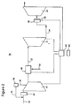
- Figure 2 is a schematic diagram of a gas turbine according to an exemplary embodiment
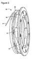
- Figure 3 is a schematic diagram of a nozzle system according to an exemplary embodiment
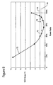
- Figure 5 is a graph showing a nozzle mechanism angle versus power according to an exemplary embodiment
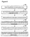
- Figure 6 is a flow chart of a method for regaining control of a stuck nozzle mechanism according to an exemplary embodiment
- Figure 7 is a schematic diagram of a controller that controls a gas turbine.
- compressed air from the compressor 44 is mixed in the combustor 48 with fuel provided by a line 50 and ignited.
- the burnt gas (exhaust gas) has a high temperature and therefore it stores kinetic energy.
- the hot exhaust gas is provided to the inlet 32 of the first stage 31 (turbine) of the gas turbine 30.
- An axial compressor which is the opposite of the gas turbine, may also be used as an example for discussing the exemplary embodiments. However, for simplicity, only the gas turbine is discussed in the exemplary embodiments.
- the IBH mechanism is schematically illustrated in Figure 2 .
- the IBH mechanism 36 diverts a part of the output medium flowing through compressor 44 along path 38 and reinserts it into an inlet 52 of the compressor 44 along path 40. If the medium is air, the diverted air is called bleed air.
- One purpose of the IBH mechanism 36 is to increase a temperature of the medium at inlet 52 as the diverted medium flowing along path 38 has a higher temperature that the medium at inlet 52.
- the IGV mechanism 42 is placed at the inlet 52 of the compressor 44 and is configured to control an amount of medium entering the compressor 44.
- the IGV 42 includes plural vanes that are configured to rotate in a certain range to increase or decrease an open area of the inlet 52.
- Figure 2 also shows a nozzle mechanism 60 displaced between first turbine 31 and second turbine 32.
- the nozzle mechanism 60 is configured to control an amount of enthalpy split between the first turbine 31 and the second turbine 32.
- Figure 3 shows an example of a nozzle mechanism 60.
- the nozzle system 60 may include a hydraulic piston 61 connected to a rotating ring 63 that modulates all the nozzles 65 simultaneously through levers to provide a variable area second stage nozzle to the gases coming from the first stage.
- a logic mechanism 62 may be attached to the gas turbine 30 or may be remotely placed but connected to various elements of the gas turbine 30 to control, for example, the nozzle mechanism 60.
- the logic 62 may be configured to also control the minimum speed reference to the first turbine 31, various parameters of the compressor 44 and the combustor 48.
- the NGV failure is detected and corrected. More specifically, in step 400, a value of the NGV angle is measured. The measured value NGB fbk (feedback value) is compared in step 402 with a set value NGV set . If a difference between the feedback value and the set value is larger than a certain value for a predetermined time, the NGV system 60 is considered to have been failed, i.e., the nozzles are stuck. In one application, an absolute function ABS is applied to the difference between the feedback and the set values. Thus, in an exemplary embodiment, the condition for a stuck NGV is given by ABS(NGV set - NGV fbk ) > 2 for around 60s.
- This method may correct the detected failure of the NGV system 60 by taking one or more of the following steps.
- the logic 62 of the gas turbine detects that the NGV system has failed, based on the above noted relation, the logic instructs in step 404 the gas turbine to increase the minimum speed TNH reference of the first turbine 31.
- the logic 62 may be a processor, dedicated circuitry, computer software or a combination thereof.
- the logic 62 may be a central device that coordinates the entire gas turbine 30 or may be distributed at the compressor, combustor, turbines, etc.
- the logic 62 may be connected to a memory 64 (see Figure 2 ) that stores the above noted predetermined values and necessary computer instructions.
- Logic 62 may be connected to one or more sensors 66 (see Figure 2 ) for detecting whether the NGV system 60 has failed.
- the sensor 66 may be configured to measure a rotation angle of the nozzles of the NGV system 60.
- the logic 62 may be connected to the compressor 44 for controlling the speed of the compressor, an intake of the compressor, etc., may be connected to the combustor 48 for controlling a mixture ratio between the compressed medium from the compressor and the fuel and other characteristics of the combustor, and also may be connected to the turbines 31 and 33 to perform other functions.
- the logic 62 may be configured to increase the minimum TNH reference to a higher value, which may vary from machine to machine. According to an exemplary embodiment, the minimum TNH reference is increased from the current value to a higher value in an open loop. For example, if the current minimum TNH reference is 94% of a nominal value, this current value may be increased to 98% of the nominal value.
- the logic 62 verifies whether the NGV system mobility is restored by repeating steps 400 and 402. If the NGV system's mobility has been restored, the method does not advance further. However, if the NGV system is still stuck, the method advances to step 408 in which, the IBH flow is increased from a current value up to a maximum value.
- step 408 After step 408 and the value of the IBH flow being at the maximum value, the method advances to step 410 for checking whether the NGV system's mobility has been restored. If this is not the case, i.e., the NGV system is still stuck, the method advances to step 412 in which an IGV angle is increased from a current value to a maximum value. In one application, the maximum value of the IGV angle is 75o degrees. Step 412 may be a closed loop as discussed above with regard to step 408.
- the logic 62 is configured to sequentially increase the minimum TNH reference, IBH flow and IGV angle and also to stop this sequence as soon as the NGV's mobility is restored.
- the sequence of TNH, IBH and IGV increase is followed and no other sequence is used.
- FIG. 5 A dependence of the NGV angle (in degrees) versus a power produced by the gas turbine is shown in Figure 5 . It is noted that as the power output of the gas turbine increases, the NGV angle initially decreases until a minimum is reached, then it increases again. It is noted that the values on the x axis of Figure 5 are for exemplary and not to limit the exemplary embodiments. Other numbers may be applicable depending on the machine, the load and other factors. As the NGV angle decreases, it reaches a point 70, at the intersection of curve 72 with sticking angle threshold 74. Point 70 characterizes, for a specific gas turbine and operating conditions, the condition for which the NGV system has failed. Thus, as the output power of the gas turbine is further increased, the NGV's angle remains constant on curve 74.
- the method described with regard to Figure 4 is activated and the TNH, IBH and IGV sequence is followed.
- the point indicating the activation of the method of Figure 4 is shown as point 78 on curve 76 in Figure 5 .
- the representative point of the NGV angle returns on curve 72.
- the method illustrated in Figure 4 may be implemented in the controller 62 in software form, circuitry form or a combination thereof.
- a software patch may be designed to include computer instructions, which when executed by a processor of the controller 62, executes one or more of the steps shown in Figure 4 .
- the software patch may be installed in existing gas turbines to correct the sticking nozzles.
- a system having a controller configured as discussed above advantageously improves a control of a high-pressure shaft speed, and/or reduces power limitations due to the sticking nozzles, and/or shorten the loss of performance of the gas turbine, and/or improves a combustor turndown capability.
- a method for controlling a stuck nozzle system installed between first and second turbines connected in series to a compressor includes a step 600 of determining whether the nozzle system is stuck, a step 602 of instructing the first turbine to increase the minimum speed reference when the nozzle system is stuck, a step 604 of verifying whether the nozzle system continues to be stuck, a step 606 of instructing the compressor to increase an inlet bleed heat (IBH) flow from a current value to a maximum value when the nozzle system is stuck, a step 608 of verifying whether the nozzle system continues to be stuck, and a step 610 of instructing the compressor to increase an inlet guide vanes (IGV) angle from a current value to a maximum value when the nozzle system is stuck.
- IBH inlet bleed heat
- the disclosed exemplary embodiments provide a system and a method for regaining control of stuck nozzles in a gas turbine or other machine. It should be understood that this description is not intended to limit the invention. On the contrary, the exemplary embodiments are intended to cover alternatives, modifications and equivalents, which are included in the spirit and scope of the invention as defined by the appended claims. Further, in the detailed description of the exemplary embodiments, numerous specific details are set forth in order to provide a comprehensive understanding of the claimed invention. However, one skilled in the art would understand that various embodiments may be practiced without such specific details.
- FIG. 7 For purposes of illustration and not of limitation, an example of a representative controller (logic mechanism) capable of carrying out operations in accordance with the exemplary embodiments is illustrated in Figure 7 . It should be recognized, however, that the principles of the present exemplary embodiments are equally applicable to other computing systems.
- the exemplary controller 700 may include a processing/control unit 702, such as a microprocessor, reduced instruction set computer (RISC), or other central processing module.
- the processing unit 702 need not be a single device, and may include one or more processors.
- the processing unit 702 may include a master processor and associated slave processors coupled to communicate with the master processor.
- the processing unit 702 may have the structure shown in Figure 2 .
- the processing unit 702 may control the basic functions of the system as dictated by programs available in the storage/memory 704. Thus, the processing unit 702 may execute the functions described in Figures 4 and 6 . More particularly, the storage/memory 704 may include an operating system and program modules for carrying out functions and applications on the controller.
- the program storage may include one or more of read-only memory (ROM), flash ROM, programmable and/or erasable ROM, random access memory (RAM), subscriber interface module (SIM), wireless interface module (WIM), smart card, or other removable memory device, etc.
- the program modules and associated features may also be transmitted to the controller 700 via data signals, such as being downloaded electronically via a network, such as the Internet.
- One of the programs that may be stored in the storage/memory 704 is a specific program 706.
- the specific program 706 may interact with various sensors or components of the gas turbine to determine whether the nozzle mechanism is stuck.
- the program 706 and associated features may be implemented in software and/or firmware operable by way of the processor 702.
- the program storage/memory 704 may also be used to store data 708, or other data associated with the present exemplary embodiments.
- the programs 706 and data 708 are stored in non-volatile electrically-erasable, programmable ROM (EEPROM), flash ROM, etc. so that the information is not lost upon power down of the controller 700.
- EEPROM electrically-erasable, programmable ROM
- the processor 702 may also be coupled to user interface 710 elements.
- the user interface 710 may include, for example, a display 712 such as a liquid crystal display, a keypad 714, speaker 716, and a microphone 718. These and other user interface components are coupled to the processor 702 as is known in the art.
- the keypad 714 may include alpha-numeric keys for performing a variety of functions, including dialing numbers and executing operations assigned to one or more keys.
- other user interface mechanisms may be employed, such as voice commands, switches, touch pad/screen, graphical user interface using a pointing device, trackball, joystick, or any other user interface mechanism.
- the controller 700 may also include a digital signal processor (DSP) 720.
- DSP digital signal processor
- the DSP 720 may perform a variety of functions, including analog-to-digital (A/D) conversion, digital-to-analog (D/A) conversion, speech coding/decoding, encryption/decryption, error detection and correction, bit stream translation, filtering, etc.
- the transceiver 722, generally coupled to an antenna 724, may transmit and receive the radio signals associated with a wireless device, e.g., a sensor.
- the controller 700 of Figure 7 is provided as a representative example of a computing environment in which the principles of the present exemplary embodiments may be applied. From the description provided herein, those skilled in the art will appreciate that the present invention is equally applicable in a variety of other currently known and future mobile and fixed computing environments.
- the specific application 706 and associated features, and data 708, may be stored in a variety of manners, may be operable on a variety of processing devices, and may be operable in electronic devices having additional, fewer, or different supporting circuitry and user interface mechanisms.
Landscapes
- Engineering & Computer Science (AREA)
- Chemical & Material Sciences (AREA)
- Combustion & Propulsion (AREA)
- Mechanical Engineering (AREA)
- General Engineering & Computer Science (AREA)
- Physics & Mathematics (AREA)
- Fluid Mechanics (AREA)
- Chemical Kinetics & Catalysis (AREA)
- General Chemical & Material Sciences (AREA)
- Control Of Turbines (AREA)
- Details Or Accessories Of Spraying Plant Or Apparatus (AREA)
- Control Of Positive-Displacement Air Blowers (AREA)
Applications Claiming Priority (1)
| Application Number | Priority Date | Filing Date | Title |
|---|---|---|---|
| ITCO2010A000023A IT1399723B1 (it) | 2010-04-30 | 2010-04-30 | Metodo e sistema per la rivelazione di ugello bloccato ed il rimedio |
Publications (2)
| Publication Number | Publication Date |
|---|---|
| EP2383452A1 true EP2383452A1 (fr) | 2011-11-02 |
| EP2383452B1 EP2383452B1 (fr) | 2013-02-20 |
Family
ID=43219094
Family Applications (1)
| Application Number | Title | Priority Date | Filing Date |
|---|---|---|---|
| EP11163664A Not-in-force EP2383452B1 (fr) | 2010-04-30 | 2011-04-26 | Système et procédé pour la détection et la correction d'une situation de blocage de tuyère |
Country Status (8)
| Country | Link |
|---|---|
| US (1) | US8676391B2 (fr) |
| EP (1) | EP2383452B1 (fr) |
| JP (1) | JP5860610B2 (fr) |
| KR (1) | KR101747438B1 (fr) |
| CN (1) | CN102287241B (fr) |
| CA (1) | CA2737333C (fr) |
| IT (1) | IT1399723B1 (fr) |
| RU (1) | RU2553845C2 (fr) |
Cited By (2)
| Publication number | Priority date | Publication date | Assignee | Title |
|---|---|---|---|---|
| WO2014052043A1 (fr) * | 2012-09-27 | 2014-04-03 | United Technologies Corporation | Programmation d'aubes à incidence variable |
| WO2016128479A1 (fr) * | 2015-02-12 | 2016-08-18 | Nuovo Pignone Tecnologie Srl | Procédé de fonctionnement permettant d'améliorer l'efficacité à charge partielle d'une turbine à gaz et turbine à gaz d'efficacité améliorée à charge partielle |
Families Citing this family (2)
| Publication number | Priority date | Publication date | Assignee | Title |
|---|---|---|---|---|
| CN102678192B (zh) * | 2012-05-28 | 2014-12-31 | 哈尔滨工业大学 | 考虑汽轮机实际运行约束的各喷嘴组的喷嘴数目优化设计方法 |
| CN108104955A (zh) * | 2017-11-24 | 2018-06-01 | 中国航发沈阳黎明航空发动机有限责任公司 | 一种航空发动机主调节计划角度与转速关系曲线调整方法 |
Citations (9)
| Publication number | Priority date | Publication date | Assignee | Title |
|---|---|---|---|---|
| JPS5189016A (fr) * | 1975-02-03 | 1976-08-04 | ||
| JPS63123737U (fr) * | 1987-02-05 | 1988-08-11 | ||
| EP0279487A2 (fr) * | 1987-02-20 | 1988-08-24 | NUOVOPIGNONE INDUSTRIE MECCANICHE E FONDERIA S.p.A. | Système de régulation pour une turbine à gaz à deux arbres |
| US5184526A (en) * | 1990-06-07 | 1993-02-09 | Toyota Jidosha Kabushiki Kaisha | Automatic speed changing system for two-shaft type gas turbine engine |
| US20040103666A1 (en) * | 2001-04-06 | 2004-06-03 | Volvo Aero Corporation | Method and arrangement for proving a gas turbine, and engine-braking therefore |
| EP1533573A1 (fr) * | 2003-11-20 | 2005-05-25 | General Electric Company | Méthode de commande pour la répartition du combustible dans une chambre de combustion de turbine à gaz |
| US20060016196A1 (en) * | 2004-07-21 | 2006-01-26 | Epstein Stanley W | Onboard supplemental power system at varying high altitudes |
| EP1770331A2 (fr) * | 2005-10-03 | 2007-04-04 | General Electric Company | Procédé pour contrôler la partition de l'air de dérivation vers la chambre de combustion de turbine |
| EP2180165A2 (fr) * | 2008-10-24 | 2010-04-28 | General Electric Company | Système et procédé pour changer l'efficacité d'une turbine à combustion |
Family Cites Families (8)
| Publication number | Priority date | Publication date | Assignee | Title |
|---|---|---|---|---|
| US3638422A (en) * | 1970-06-26 | 1972-02-01 | Gen Electric | Two-shaft gas turbine control system |
| SU1767204A1 (ru) * | 1990-04-25 | 1992-10-07 | Государственный научно-исследовательский институт гражданской авиации | Комбинированна силова установка летательного аппарата |
| JPH04175425A (ja) * | 1990-11-07 | 1992-06-23 | Toyota Motor Corp | ガスタービン機関の可変ノズル駆動装置 |
| US6226974B1 (en) * | 1999-06-25 | 2001-05-08 | General Electric Co. | Method of operation of industrial gas turbine for optimal performance |
| RU2300652C2 (ru) * | 2004-12-09 | 2007-06-10 | Виктор Борисович Лужинский | Газотурбинный двигатель |
| US20090067993A1 (en) * | 2007-03-22 | 2009-03-12 | Roberge Gary D | Coated variable area fan nozzle |
| US20090053036A1 (en) * | 2007-08-24 | 2009-02-26 | General Electric Company | Systems and Methods for Extending Gas Turbine Emissions Compliance |
| US8528429B2 (en) * | 2010-01-20 | 2013-09-10 | Babcock & Wilcox Power Generation Group, Inc. | System and method for stabilizing a sensor |
-
2010
- 2010-04-30 IT ITCO2010A000023A patent/IT1399723B1/it active
-
2011
- 2011-04-14 CA CA2737333A patent/CA2737333C/fr not_active Expired - Fee Related
- 2011-04-21 US US13/091,525 patent/US8676391B2/en active Active
- 2011-04-21 JP JP2011094560A patent/JP5860610B2/ja not_active Expired - Fee Related
- 2011-04-26 EP EP11163664A patent/EP2383452B1/fr not_active Not-in-force
- 2011-04-28 RU RU2011116899/06A patent/RU2553845C2/ru active
- 2011-04-28 KR KR1020110040269A patent/KR101747438B1/ko active IP Right Grant
- 2011-04-28 CN CN201110118214.5A patent/CN102287241B/zh not_active Expired - Fee Related
Patent Citations (9)
| Publication number | Priority date | Publication date | Assignee | Title |
|---|---|---|---|---|
| JPS5189016A (fr) * | 1975-02-03 | 1976-08-04 | ||
| JPS63123737U (fr) * | 1987-02-05 | 1988-08-11 | ||
| EP0279487A2 (fr) * | 1987-02-20 | 1988-08-24 | NUOVOPIGNONE INDUSTRIE MECCANICHE E FONDERIA S.p.A. | Système de régulation pour une turbine à gaz à deux arbres |
| US5184526A (en) * | 1990-06-07 | 1993-02-09 | Toyota Jidosha Kabushiki Kaisha | Automatic speed changing system for two-shaft type gas turbine engine |
| US20040103666A1 (en) * | 2001-04-06 | 2004-06-03 | Volvo Aero Corporation | Method and arrangement for proving a gas turbine, and engine-braking therefore |
| EP1533573A1 (fr) * | 2003-11-20 | 2005-05-25 | General Electric Company | Méthode de commande pour la répartition du combustible dans une chambre de combustion de turbine à gaz |
| US20060016196A1 (en) * | 2004-07-21 | 2006-01-26 | Epstein Stanley W | Onboard supplemental power system at varying high altitudes |
| EP1770331A2 (fr) * | 2005-10-03 | 2007-04-04 | General Electric Company | Procédé pour contrôler la partition de l'air de dérivation vers la chambre de combustion de turbine |
| EP2180165A2 (fr) * | 2008-10-24 | 2010-04-28 | General Electric Company | Système et procédé pour changer l'efficacité d'une turbine à combustion |
Cited By (4)
| Publication number | Priority date | Publication date | Assignee | Title |
|---|---|---|---|---|
| WO2014052043A1 (fr) * | 2012-09-27 | 2014-04-03 | United Technologies Corporation | Programmation d'aubes à incidence variable |
| US10267326B2 (en) | 2012-09-27 | 2019-04-23 | United Technologies Corporation | Variable vane scheduling |
| WO2016128479A1 (fr) * | 2015-02-12 | 2016-08-18 | Nuovo Pignone Tecnologie Srl | Procédé de fonctionnement permettant d'améliorer l'efficacité à charge partielle d'une turbine à gaz et turbine à gaz d'efficacité améliorée à charge partielle |
| US10871109B2 (en) | 2015-02-12 | 2020-12-22 | Nuovo Pignone Tecnologie Srl | Operation method for improving partial load efficiency in a gas turbine and gas turbine with improved partial load efficiency |
Also Published As
| Publication number | Publication date |
|---|---|
| JP5860610B2 (ja) | 2016-02-16 |
| ITCO20100023A1 (it) | 2011-10-31 |
| JP2011236895A (ja) | 2011-11-24 |
| CN102287241B (zh) | 2015-06-17 |
| IT1399723B1 (it) | 2013-05-03 |
| KR101747438B1 (ko) | 2017-06-14 |
| KR20110121570A (ko) | 2011-11-07 |
| US20110270447A1 (en) | 2011-11-03 |
| EP2383452B1 (fr) | 2013-02-20 |
| US8676391B2 (en) | 2014-03-18 |
| CA2737333C (fr) | 2017-08-08 |
| RU2553845C2 (ru) | 2015-06-20 |
| CN102287241A (zh) | 2011-12-21 |
| RU2011116899A (ru) | 2012-11-10 |
| CA2737333A1 (fr) | 2011-10-30 |
Similar Documents
| Publication | Publication Date | Title |
|---|---|---|
| JP5508892B2 (ja) | エンジン・ターンダウンのために圧縮機抽出空気流を制御するシステム及び方法 | |
| KR101908200B1 (ko) | 증기 분사 기구를 갖는 2축식 가스 터빈 | |
| EP2372108B1 (fr) | Procédé et système pour tester le système de protection contre l'excès de vitesse d'une machine de centrale électrique | |
| US8365583B2 (en) | Method and system for testing an overspeed protection system of a powerplant machine | |
| EP2559862B1 (fr) | Contrôle d'une vanne de soutirage en réponse à une soudaine diminution de charge dans une turbine à gaz | |
| EP2383452B1 (fr) | Système et procédé pour la détection et la correction d'une situation de blocage de tuyère | |
| CN111664009A (zh) | 机器学习在处理涡轮发动机的高频传感器信号中的应用 | |
| US8370100B2 (en) | Method for determining when to perform a test of an overspeed protection system of a powerplant machine | |
| CN112128133B (zh) | 高压压气机可调静叶打开裕度测量试验方法 | |
| EP3763927B1 (fr) | Dispositif de commande d'alimentation en carburant | |
| EP2369142B1 (fr) | Procédé et système pour tester le système de protection contre la survitesse d'une centrale électrique | |
| CN111295503A (zh) | 燃气涡轮发动机以及控制方法 | |
| US20210285386A1 (en) | Method and system for determining an engine temperature | |
| US9677686B2 (en) | Control process for operation of valves of a gas supply device of the gas turbine | |
| CN106907245B (zh) | 燃料供应系统及控制燃气涡轮发动机中的超速事件的方法 | |
| JP2017110649A (ja) | 排気ガスダンパおよび圧縮ガス供給源を介してガスタービン排気エネルギーを制御するためのシステムおよび方法 | |
| RU2214535C2 (ru) | Способ управления перепуском воздуха в компрессоре двухвального двухконтурного газотурбинного двигателя | |
| RU2795359C1 (ru) | Способ управления входным направляющим аппаратом компрессора газотурбинного двигателя | |
| KR20210121942A (ko) | 보조 동력 유닛 제어 시스템 및 방법 | |
| JP2020084841A (ja) | 二軸式ガスタービン | |
| CN112534120A (zh) | 联合循环发电设备 |
Legal Events
| Date | Code | Title | Description |
|---|---|---|---|
| AK | Designated contracting states |
Kind code of ref document: A1 Designated state(s): AL AT BE BG CH CY CZ DE DK EE ES FI FR GB GR HR HU IE IS IT LI LT LU LV MC MK MT NL NO PL PT RO RS SE SI SK SM TR |
|
| AX | Request for extension of the european patent |
Extension state: BA ME |
|
| PUAI | Public reference made under article 153(3) epc to a published international application that has entered the european phase |
Free format text: ORIGINAL CODE: 0009012 |
|
| 17P | Request for examination filed |
Effective date: 20120502 |
|
| GRAP | Despatch of communication of intention to grant a patent |
Free format text: ORIGINAL CODE: EPIDOSNIGR1 |
|
| GRAS | Grant fee paid |
Free format text: ORIGINAL CODE: EPIDOSNIGR3 |
|
| GRAA | (expected) grant |
Free format text: ORIGINAL CODE: 0009210 |
|
| AK | Designated contracting states |
Kind code of ref document: B1 Designated state(s): AL AT BE BG CH CY CZ DE DK EE ES FI FR GB GR HR HU IE IS IT LI LT LU LV MC MK MT NL NO PL PT RO RS SE SI SK SM TR |
|
| REG | Reference to a national code |
Ref country code: GB Ref legal event code: FG4D |
|
| REG | Reference to a national code |
Ref country code: CH Ref legal event code: EP |
|
| REG | Reference to a national code |
Ref country code: AT Ref legal event code: REF Ref document number: 597667 Country of ref document: AT Kind code of ref document: T Effective date: 20130315 |
|
| REG | Reference to a national code |
Ref country code: IE Ref legal event code: FG4D |
|
| REG | Reference to a national code |
Ref country code: CH Ref legal event code: NV Representative=s name: SERVOPATENT GMBH, CH |
|
| REG | Reference to a national code |
Ref country code: DE Ref legal event code: R096 Ref document number: 602011000914 Country of ref document: DE Effective date: 20130418 |
|
| REG | Reference to a national code |
Ref country code: NL Ref legal event code: T3 |
|
| REG | Reference to a national code |
Ref country code: NO Ref legal event code: T2 Effective date: 20130220 |
|
| REG | Reference to a national code |
Ref country code: AT Ref legal event code: MK05 Ref document number: 597667 Country of ref document: AT Kind code of ref document: T Effective date: 20130220 |
|
| REG | Reference to a national code |
Ref country code: LT Ref legal event code: MG4D |
|
| PG25 | Lapsed in a contracting state [announced via postgrant information from national office to epo] |
Ref country code: SE Free format text: LAPSE BECAUSE OF FAILURE TO SUBMIT A TRANSLATION OF THE DESCRIPTION OR TO PAY THE FEE WITHIN THE PRESCRIBED TIME-LIMIT Effective date: 20130220 Ref country code: LT Free format text: LAPSE BECAUSE OF FAILURE TO SUBMIT A TRANSLATION OF THE DESCRIPTION OR TO PAY THE FEE WITHIN THE PRESCRIBED TIME-LIMIT Effective date: 20130220 Ref country code: AT Free format text: LAPSE BECAUSE OF FAILURE TO SUBMIT A TRANSLATION OF THE DESCRIPTION OR TO PAY THE FEE WITHIN THE PRESCRIBED TIME-LIMIT Effective date: 20130220 Ref country code: BG Free format text: LAPSE BECAUSE OF FAILURE TO SUBMIT A TRANSLATION OF THE DESCRIPTION OR TO PAY THE FEE WITHIN THE PRESCRIBED TIME-LIMIT Effective date: 20130520 Ref country code: IS Free format text: LAPSE BECAUSE OF FAILURE TO SUBMIT A TRANSLATION OF THE DESCRIPTION OR TO PAY THE FEE WITHIN THE PRESCRIBED TIME-LIMIT Effective date: 20130620 Ref country code: ES Free format text: LAPSE BECAUSE OF FAILURE TO SUBMIT A TRANSLATION OF THE DESCRIPTION OR TO PAY THE FEE WITHIN THE PRESCRIBED TIME-LIMIT Effective date: 20130531 |
|
| PG25 | Lapsed in a contracting state [announced via postgrant information from national office to epo] |
Ref country code: GR Free format text: LAPSE BECAUSE OF FAILURE TO SUBMIT A TRANSLATION OF THE DESCRIPTION OR TO PAY THE FEE WITHIN THE PRESCRIBED TIME-LIMIT Effective date: 20130521 Ref country code: SI Free format text: LAPSE BECAUSE OF FAILURE TO SUBMIT A TRANSLATION OF THE DESCRIPTION OR TO PAY THE FEE WITHIN THE PRESCRIBED TIME-LIMIT Effective date: 20130220 Ref country code: BE Free format text: LAPSE BECAUSE OF FAILURE TO SUBMIT A TRANSLATION OF THE DESCRIPTION OR TO PAY THE FEE WITHIN THE PRESCRIBED TIME-LIMIT Effective date: 20130220 Ref country code: FI Free format text: LAPSE BECAUSE OF FAILURE TO SUBMIT A TRANSLATION OF THE DESCRIPTION OR TO PAY THE FEE WITHIN THE PRESCRIBED TIME-LIMIT Effective date: 20130220 Ref country code: PT Free format text: LAPSE BECAUSE OF FAILURE TO SUBMIT A TRANSLATION OF THE DESCRIPTION OR TO PAY THE FEE WITHIN THE PRESCRIBED TIME-LIMIT Effective date: 20130620 Ref country code: PL Free format text: LAPSE BECAUSE OF FAILURE TO SUBMIT A TRANSLATION OF THE DESCRIPTION OR TO PAY THE FEE WITHIN THE PRESCRIBED TIME-LIMIT Effective date: 20130220 Ref country code: LV Free format text: LAPSE BECAUSE OF FAILURE TO SUBMIT A TRANSLATION OF THE DESCRIPTION OR TO PAY THE FEE WITHIN THE PRESCRIBED TIME-LIMIT Effective date: 20130220 |
|
| PG25 | Lapsed in a contracting state [announced via postgrant information from national office to epo] |
Ref country code: HR Free format text: LAPSE BECAUSE OF FAILURE TO SUBMIT A TRANSLATION OF THE DESCRIPTION OR TO PAY THE FEE WITHIN THE PRESCRIBED TIME-LIMIT Effective date: 20130220 Ref country code: RS Free format text: LAPSE BECAUSE OF FAILURE TO SUBMIT A TRANSLATION OF THE DESCRIPTION OR TO PAY THE FEE WITHIN THE PRESCRIBED TIME-LIMIT Effective date: 20130220 |
|
| PG25 | Lapsed in a contracting state [announced via postgrant information from national office to epo] |
Ref country code: RO Free format text: LAPSE BECAUSE OF FAILURE TO SUBMIT A TRANSLATION OF THE DESCRIPTION OR TO PAY THE FEE WITHIN THE PRESCRIBED TIME-LIMIT Effective date: 20130220 Ref country code: SK Free format text: LAPSE BECAUSE OF FAILURE TO SUBMIT A TRANSLATION OF THE DESCRIPTION OR TO PAY THE FEE WITHIN THE PRESCRIBED TIME-LIMIT Effective date: 20130220 Ref country code: CZ Free format text: LAPSE BECAUSE OF FAILURE TO SUBMIT A TRANSLATION OF THE DESCRIPTION OR TO PAY THE FEE WITHIN THE PRESCRIBED TIME-LIMIT Effective date: 20130220 Ref country code: DK Free format text: LAPSE BECAUSE OF FAILURE TO SUBMIT A TRANSLATION OF THE DESCRIPTION OR TO PAY THE FEE WITHIN THE PRESCRIBED TIME-LIMIT Effective date: 20130220 Ref country code: EE Free format text: LAPSE BECAUSE OF FAILURE TO SUBMIT A TRANSLATION OF THE DESCRIPTION OR TO PAY THE FEE WITHIN THE PRESCRIBED TIME-LIMIT Effective date: 20130220 |
|
| PG25 | Lapsed in a contracting state [announced via postgrant information from national office to epo] |
Ref country code: MC Free format text: LAPSE BECAUSE OF FAILURE TO SUBMIT A TRANSLATION OF THE DESCRIPTION OR TO PAY THE FEE WITHIN THE PRESCRIBED TIME-LIMIT Effective date: 20130220 |
|
| PLBE | No opposition filed within time limit |
Free format text: ORIGINAL CODE: 0009261 |
|
| STAA | Information on the status of an ep patent application or granted ep patent |
Free format text: STATUS: NO OPPOSITION FILED WITHIN TIME LIMIT |
|
| PG25 | Lapsed in a contracting state [announced via postgrant information from national office to epo] |
Ref country code: IT Free format text: LAPSE BECAUSE OF FAILURE TO SUBMIT A TRANSLATION OF THE DESCRIPTION OR TO PAY THE FEE WITHIN THE PRESCRIBED TIME-LIMIT Effective date: 20130220 |
|
| 26N | No opposition filed |
Effective date: 20131121 |
|
| REG | Reference to a national code |
Ref country code: IE Ref legal event code: MM4A |
|
| REG | Reference to a national code |
Ref country code: DE Ref legal event code: R097 Ref document number: 602011000914 Country of ref document: DE Effective date: 20131121 |
|
| PG25 | Lapsed in a contracting state [announced via postgrant information from national office to epo] |
Ref country code: IE Free format text: LAPSE BECAUSE OF NON-PAYMENT OF DUE FEES Effective date: 20130426 |
|
| PG25 | Lapsed in a contracting state [announced via postgrant information from national office to epo] |
Ref country code: MT Free format text: LAPSE BECAUSE OF FAILURE TO SUBMIT A TRANSLATION OF THE DESCRIPTION OR TO PAY THE FEE WITHIN THE PRESCRIBED TIME-LIMIT Effective date: 20130220 |
|
| PG25 | Lapsed in a contracting state [announced via postgrant information from national office to epo] |
Ref country code: SM Free format text: LAPSE BECAUSE OF FAILURE TO SUBMIT A TRANSLATION OF THE DESCRIPTION OR TO PAY THE FEE WITHIN THE PRESCRIBED TIME-LIMIT Effective date: 20130220 |
|
| PG25 | Lapsed in a contracting state [announced via postgrant information from national office to epo] |
Ref country code: TR Free format text: LAPSE BECAUSE OF FAILURE TO SUBMIT A TRANSLATION OF THE DESCRIPTION OR TO PAY THE FEE WITHIN THE PRESCRIBED TIME-LIMIT Effective date: 20130220 Ref country code: CY Free format text: LAPSE BECAUSE OF FAILURE TO SUBMIT A TRANSLATION OF THE DESCRIPTION OR TO PAY THE FEE WITHIN THE PRESCRIBED TIME-LIMIT Effective date: 20130220 |
|
| PG25 | Lapsed in a contracting state [announced via postgrant information from national office to epo] |
Ref country code: LU Free format text: LAPSE BECAUSE OF NON-PAYMENT OF DUE FEES Effective date: 20130426 Ref country code: MK Free format text: LAPSE BECAUSE OF FAILURE TO SUBMIT A TRANSLATION OF THE DESCRIPTION OR TO PAY THE FEE WITHIN THE PRESCRIBED TIME-LIMIT Effective date: 20130220 Ref country code: HU Free format text: LAPSE BECAUSE OF FAILURE TO SUBMIT A TRANSLATION OF THE DESCRIPTION OR TO PAY THE FEE WITHIN THE PRESCRIBED TIME-LIMIT; INVALID AB INITIO Effective date: 20110426 |
|
| REG | Reference to a national code |
Ref country code: FR Ref legal event code: PLFP Year of fee payment: 6 |
|
| REG | Reference to a national code |
Ref country code: FR Ref legal event code: PLFP Year of fee payment: 7 |
|
| REG | Reference to a national code |
Ref country code: FR Ref legal event code: PLFP Year of fee payment: 8 |
|
| PG25 | Lapsed in a contracting state [announced via postgrant information from national office to epo] |
Ref country code: AL Free format text: LAPSE BECAUSE OF FAILURE TO SUBMIT A TRANSLATION OF THE DESCRIPTION OR TO PAY THE FEE WITHIN THE PRESCRIBED TIME-LIMIT Effective date: 20130220 |
|
| REG | Reference to a national code |
Ref country code: CH Ref legal event code: PCAR Free format text: NEW ADDRESS: WANNERSTRASSE 9/1, 8045 ZUERICH (CH) |
|
| PGFP | Annual fee paid to national office [announced via postgrant information from national office to epo] |
Ref country code: FR Payment date: 20210323 Year of fee payment: 11 Ref country code: CH Payment date: 20210326 Year of fee payment: 11 Ref country code: NO Payment date: 20210325 Year of fee payment: 11 Ref country code: NL Payment date: 20210329 Year of fee payment: 11 |
|
| PGFP | Annual fee paid to national office [announced via postgrant information from national office to epo] |
Ref country code: GB Payment date: 20210324 Year of fee payment: 11 |
|
| PGFP | Annual fee paid to national office [announced via postgrant information from national office to epo] |
Ref country code: DE Payment date: 20210323 Year of fee payment: 11 |
|
| REG | Reference to a national code |
Ref country code: NO Ref legal event code: CHAD Owner name: NUOVO PIGNONE INTERNATIONAL S.R.L., IT |
|
| REG | Reference to a national code |
Ref country code: NO Ref legal event code: CHAD Owner name: NUOVO PIGNONE TECNOLOGIE - S.R.L., IT |
|
| REG | Reference to a national code |
Ref country code: CH Ref legal event code: PK Free format text: BERICHTIGUNGEN |
|
| REG | Reference to a national code |
Ref country code: NL Ref legal event code: PD Owner name: NUOVO PIGNONE TECNOLOGIE - S.R.L.; IT Free format text: DETAILS ASSIGNMENT: CHANGE OF OWNER(S), ASSIGNMENT; FORMER OWNER NAME: NUOVO PIGNONE S.R.L. Effective date: 20220621 |
|
| REG | Reference to a national code |
Ref country code: GB Ref legal event code: 732E Free format text: REGISTERED BETWEEN 20220728 AND 20220803 |
|
| REG | Reference to a national code |
Ref country code: DE Ref legal event code: R119 Ref document number: 602011000914 Country of ref document: DE |
|
| REG | Reference to a national code |
Ref country code: NO Ref legal event code: MMEP |
|
| REG | Reference to a national code |
Ref country code: CH Ref legal event code: PL |
|
| REG | Reference to a national code |
Ref country code: NL Ref legal event code: MM Effective date: 20220501 |
|
| GBPC | Gb: european patent ceased through non-payment of renewal fee |
Effective date: 20220426 |
|
| PG25 | Lapsed in a contracting state [announced via postgrant information from national office to epo] |
Ref country code: NO Free format text: LAPSE BECAUSE OF NON-PAYMENT OF DUE FEES Effective date: 20220430 Ref country code: NL Free format text: LAPSE BECAUSE OF NON-PAYMENT OF DUE FEES Effective date: 20220501 Ref country code: LI Free format text: LAPSE BECAUSE OF NON-PAYMENT OF DUE FEES Effective date: 20220430 Ref country code: GB Free format text: LAPSE BECAUSE OF NON-PAYMENT OF DUE FEES Effective date: 20220426 Ref country code: FR Free format text: LAPSE BECAUSE OF NON-PAYMENT OF DUE FEES Effective date: 20220430 Ref country code: DE Free format text: LAPSE BECAUSE OF NON-PAYMENT OF DUE FEES Effective date: 20221103 Ref country code: CH Free format text: LAPSE BECAUSE OF NON-PAYMENT OF DUE FEES Effective date: 20220430 |