EP2383233A2 - Optical fiber with differential birefringence mechanism - Google Patents
Optical fiber with differential birefringence mechanism Download PDFInfo
- Publication number
- EP2383233A2 EP2383233A2 EP11162965A EP11162965A EP2383233A2 EP 2383233 A2 EP2383233 A2 EP 2383233A2 EP 11162965 A EP11162965 A EP 11162965A EP 11162965 A EP11162965 A EP 11162965A EP 2383233 A2 EP2383233 A2 EP 2383233A2
- Authority
- EP
- European Patent Office
- Prior art keywords
- rods
- stress
- cladding
- optical fiber
- core
- Prior art date
- Legal status (The legal status is an assumption and is not a legal conclusion. Google has not performed a legal analysis and makes no representation as to the accuracy of the status listed.)
- Withdrawn
Links
- 239000013307 optical fiber Substances 0.000 title claims abstract description 48
- 238000005253 cladding Methods 0.000 claims abstract description 77
- VYPSYNLAJGMNEJ-UHFFFAOYSA-N Silicium dioxide Chemical compound O=[Si]=O VYPSYNLAJGMNEJ-UHFFFAOYSA-N 0.000 claims description 100
- 239000000835 fiber Substances 0.000 claims description 86
- 239000000377 silicon dioxide Substances 0.000 claims description 45
- 239000011521 glass Substances 0.000 claims description 31
- 239000000463 material Substances 0.000 claims description 29
- 235000012239 silicon dioxide Nutrition 0.000 claims description 26
- 230000010287 polarization Effects 0.000 claims description 24
- 229910052796 boron Inorganic materials 0.000 claims description 19
- 238000000034 method Methods 0.000 claims description 12
- 229910052801 chlorine Inorganic materials 0.000 claims description 11
- YBMRDBCBODYGJE-UHFFFAOYSA-N germanium dioxide Chemical compound O=[Ge]=O YBMRDBCBODYGJE-UHFFFAOYSA-N 0.000 claims description 10
- 239000002019 doping agent Substances 0.000 claims description 9
- 238000004519 manufacturing process Methods 0.000 claims description 5
- 239000011162 core material Substances 0.000 description 67
- 239000000460 chlorine Substances 0.000 description 14
- ZOXJGFHDIHLPTG-UHFFFAOYSA-N Boron Chemical compound [B] ZOXJGFHDIHLPTG-UHFFFAOYSA-N 0.000 description 13
- 229910052681 coesite Inorganic materials 0.000 description 9
- 229910052906 cristobalite Inorganic materials 0.000 description 9
- 229910052682 stishovite Inorganic materials 0.000 description 9
- 229910052905 tridymite Inorganic materials 0.000 description 9
- ZAMOUSCENKQFHK-UHFFFAOYSA-N Chlorine atom Chemical compound [Cl] ZAMOUSCENKQFHK-UHFFFAOYSA-N 0.000 description 5
- 239000000203 mixture Substances 0.000 description 5
- 230000003287 optical effect Effects 0.000 description 5
- 230000001939 inductive effect Effects 0.000 description 4
- 239000004071 soot Substances 0.000 description 4
- 230000008901 benefit Effects 0.000 description 3
- 230000000052 comparative effect Effects 0.000 description 3
- 208000025174 PANDAS Diseases 0.000 description 2
- 208000021155 Paediatric autoimmune neuropsychiatric disorders associated with streptococcal infection Diseases 0.000 description 2
- 240000004718 Panda Species 0.000 description 2
- 235000016496 Panda oleosa Nutrition 0.000 description 2
- 230000005540 biological transmission Effects 0.000 description 2
- 238000007596 consolidation process Methods 0.000 description 2
- 229920006240 drawn fiber Polymers 0.000 description 2
- 238000001035 drying Methods 0.000 description 2
- 230000001965 increasing effect Effects 0.000 description 2
- 238000012986 modification Methods 0.000 description 2
- 230000004048 modification Effects 0.000 description 2
- 229910052761 rare earth metal Inorganic materials 0.000 description 2
- 150000002910 rare earth metals Chemical class 0.000 description 2
- 238000005245 sintering Methods 0.000 description 2
- 230000003595 spectral effect Effects 0.000 description 2
- UGFAIRIUMAVXCW-UHFFFAOYSA-N Carbon monoxide Chemical compound [O+]#[C-] UGFAIRIUMAVXCW-UHFFFAOYSA-N 0.000 description 1
- 238000013459 approach Methods 0.000 description 1
- 230000003190 augmentative effect Effects 0.000 description 1
- 230000015572 biosynthetic process Effects 0.000 description 1
- 229910002091 carbon monoxide Inorganic materials 0.000 description 1
- 230000008878 coupling Effects 0.000 description 1
- 238000010168 coupling process Methods 0.000 description 1
- 238000005859 coupling reaction Methods 0.000 description 1
- 238000007872 degassing Methods 0.000 description 1
- 238000013461 design Methods 0.000 description 1
- 230000000694 effects Effects 0.000 description 1
- 230000001747 exhibiting effect Effects 0.000 description 1
- 238000012681 fiber drawing Methods 0.000 description 1
- 239000012530 fluid Substances 0.000 description 1
- 125000002887 hydroxy group Chemical group [H]O* 0.000 description 1
- 230000036039 immunity Effects 0.000 description 1
- 238000003780 insertion Methods 0.000 description 1
- 230000037431 insertion Effects 0.000 description 1
- 238000012423 maintenance Methods 0.000 description 1
- 238000001228 spectrum Methods 0.000 description 1
- 239000000126 substance Substances 0.000 description 1
Images


Classifications
-
- C—CHEMISTRY; METALLURGY
- C03—GLASS; MINERAL OR SLAG WOOL
- C03B—MANUFACTURE, SHAPING, OR SUPPLEMENTARY PROCESSES
- C03B37/00—Manufacture or treatment of flakes, fibres, or filaments from softened glass, minerals, or slags
- C03B37/01—Manufacture of glass fibres or filaments
- C03B37/012—Manufacture of preforms for drawing fibres or filaments
- C03B37/01205—Manufacture of preforms for drawing fibres or filaments starting from tubes, rods, fibres or filaments
- C03B37/01211—Manufacture of preforms for drawing fibres or filaments starting from tubes, rods, fibres or filaments by inserting one or more rods or tubes into a tube
- C03B37/01217—Manufacture of preforms for drawing fibres or filaments starting from tubes, rods, fibres or filaments by inserting one or more rods or tubes into a tube for making preforms of polarisation-maintaining optical fibres
-
- C—CHEMISTRY; METALLURGY
- C03—GLASS; MINERAL OR SLAG WOOL
- C03B—MANUFACTURE, SHAPING, OR SUPPLEMENTARY PROCESSES
- C03B37/00—Manufacture or treatment of flakes, fibres, or filaments from softened glass, minerals, or slags
- C03B37/01—Manufacture of glass fibres or filaments
- C03B37/012—Manufacture of preforms for drawing fibres or filaments
- C03B37/01205—Manufacture of preforms for drawing fibres or filaments starting from tubes, rods, fibres or filaments
- C03B37/01225—Means for changing or stabilising the shape, e.g. diameter, of tubes or rods in general, e.g. collapsing
- C03B37/01228—Removal of preform material
- C03B37/01231—Removal of preform material to form a longitudinal hole, e.g. by drilling
-
- C—CHEMISTRY; METALLURGY
- C03—GLASS; MINERAL OR SLAG WOOL
- C03B—MANUFACTURE, SHAPING, OR SUPPLEMENTARY PROCESSES
- C03B37/00—Manufacture or treatment of flakes, fibres, or filaments from softened glass, minerals, or slags
- C03B37/01—Manufacture of glass fibres or filaments
- C03B37/012—Manufacture of preforms for drawing fibres or filaments
- C03B37/014—Manufacture of preforms for drawing fibres or filaments made entirely or partially by chemical means, e.g. vapour phase deposition of bulk porous glass either by outside vapour deposition [OVD], or by outside vapour phase oxidation [OVPO] or by vapour axial deposition [VAD]
- C03B37/01446—Thermal after-treatment of preforms, e.g. dehydrating, consolidating, sintering
-
- C—CHEMISTRY; METALLURGY
- C03—GLASS; MINERAL OR SLAG WOOL
- C03B—MANUFACTURE, SHAPING, OR SUPPLEMENTARY PROCESSES
- C03B37/00—Manufacture or treatment of flakes, fibres, or filaments from softened glass, minerals, or slags
- C03B37/01—Manufacture of glass fibres or filaments
- C03B37/02—Manufacture of glass fibres or filaments by drawing or extruding, e.g. direct drawing of molten glass from nozzles; Cooling fins therefor
- C03B37/025—Manufacture of glass fibres or filaments by drawing or extruding, e.g. direct drawing of molten glass from nozzles; Cooling fins therefor from reheated softened tubes, rods, fibres or filaments, e.g. drawing fibres from preforms
- C03B37/027—Fibres composed of different sorts of glass, e.g. glass optical fibres
- C03B37/02709—Polarisation maintaining fibres, e.g. PM, PANDA, bi-refringent optical fibres
-
- G—PHYSICS
- G02—OPTICS
- G02B—OPTICAL ELEMENTS, SYSTEMS OR APPARATUS
- G02B6/00—Light guides; Structural details of arrangements comprising light guides and other optical elements, e.g. couplings
- G02B6/02—Optical fibres with cladding with or without a coating
- G02B6/024—Optical fibres with cladding with or without a coating with polarisation maintaining properties
-
- C—CHEMISTRY; METALLURGY
- C03—GLASS; MINERAL OR SLAG WOOL
- C03B—MANUFACTURE, SHAPING, OR SUPPLEMENTARY PROCESSES
- C03B2201/00—Type of glass produced
- C03B2201/06—Doped silica-based glasses
- C03B2201/08—Doped silica-based glasses doped with boron or fluorine or other refractive index decreasing dopant
-
- C—CHEMISTRY; METALLURGY
- C03—GLASS; MINERAL OR SLAG WOOL
- C03B—MANUFACTURE, SHAPING, OR SUPPLEMENTARY PROCESSES
- C03B2201/00—Type of glass produced
- C03B2201/06—Doped silica-based glasses
- C03B2201/08—Doped silica-based glasses doped with boron or fluorine or other refractive index decreasing dopant
- C03B2201/10—Doped silica-based glasses doped with boron or fluorine or other refractive index decreasing dopant doped with boron
-
- C—CHEMISTRY; METALLURGY
- C03—GLASS; MINERAL OR SLAG WOOL
- C03B—MANUFACTURE, SHAPING, OR SUPPLEMENTARY PROCESSES
- C03B2201/00—Type of glass produced
- C03B2201/06—Doped silica-based glasses
- C03B2201/30—Doped silica-based glasses doped with metals, e.g. Ga, Sn, Sb, Pb or Bi
- C03B2201/31—Doped silica-based glasses doped with metals, e.g. Ga, Sn, Sb, Pb or Bi doped with germanium
-
- C—CHEMISTRY; METALLURGY
- C03—GLASS; MINERAL OR SLAG WOOL
- C03B—MANUFACTURE, SHAPING, OR SUPPLEMENTARY PROCESSES
- C03B2203/00—Fibre product details, e.g. structure, shape
- C03B2203/30—Polarisation maintaining [PM], i.e. birefringent products, e.g. with elliptical core, by use of stress rods, "PANDA" type fibres
- C03B2203/302—Non-circular core cross-sections
-
- C—CHEMISTRY; METALLURGY
- C03—GLASS; MINERAL OR SLAG WOOL
- C03B—MANUFACTURE, SHAPING, OR SUPPLEMENTARY PROCESSES
- C03B2203/00—Fibre product details, e.g. structure, shape
- C03B2203/30—Polarisation maintaining [PM], i.e. birefringent products, e.g. with elliptical core, by use of stress rods, "PANDA" type fibres
- C03B2203/31—Polarisation maintaining [PM], i.e. birefringent products, e.g. with elliptical core, by use of stress rods, "PANDA" type fibres by use of stress-imparting rods, e.g. by insertion
Definitions
- the disclosure relates generally to optical waveguide fibers, and more particularly to optical fibers exhibiting single polarization or polarization maintenance properties, and/or high birefringence.
- Optical fiber has become a favorite medium for telecommunications due to its high capacity and immunity to electrical noise.
- Polarization maintaining (PM) fibers and single polarization (SP) fibers have been widely used to produce linear polarized output in optical systems. These fibers are useful for ultra-high speed transmission systems and are also utilized as couplers' fiber for use with, and connection to, optical components (e.g., lasers, EDFAs, optical instruments, interferometric sensors, and fiber gyroscopes).
- the single polarization fibers and polarization maintaining fibers can either be active, which means that they are rare earth doped in the fiber core, or passive, which means no rare earth dopants are involved.
- the polarization characteristic of single polarization fiber means that the fiber propagates one, and only one, of two orthogonally polarized polarizations within a single polarization band while suppressing the other polarization by dramatically increasing its transmission loss.
- Polarization maintaining fibers can maintain the input linear polarization on one of two orthogonally oriented axes. These fibers are not single polarization fibers.
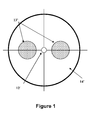
- a common polarization maintaining fiber (referred to as PANDA PM fiber herein) includes, as shown in FIG. 1 , a circular core 12' surrounded by a pure silica cladding region 14' with two stress-inducing regions 13' (two stress rods) situated therein. Core 12' and the cladding region 14' are formed of conventional materials employed in the formation of optical fibers. The refractive index of the core material is greater than that of the cladding material.
- the two stress-inducing regions 13' are formed of the same glass material, and thus have the same Coefficients of Thermal Expansion (CTE).
- the two stress-inducing regions 13' also have composition different from core and cladding materials, and a CTE different from that of cladding material 14' .
- the longitudinally-extending stress-inducing regions 13' will shrink by a different amount than that of the cladding material, whereby fiber core 12' will be put into a state of mechanical strain.
- Strain induced birefringence (otherwise referred to a stress-induced birefringence) is imparted in the fiber and thereby reduces coupling between the two orthogonally polarized fundamental modes.
- Refractive index profile is the relationship between the optical fiber material refractive index and the optical fiber radius (as measured from the centerline of the optical fiber) over a selected portion of the fiber.
- Birefringence is the difference between the effective refractive indices of the two orthogonally polarized states of the fundamental mode in optical fiber.
- the radii of the fiber segments are generally defined in terms of points where the index of refraction of the material changes because the material used takes on a different composition.
- the central core has an inner radius of zero because the first point of the segment is on the centerline.
- the outer radius of the central core segment is the radius drawn from the waveguide centerline to the last point of the refractive index of the central core having a positive delta.
- the radius of the waveguide centerline to the location of its first refractive index point is the inner radius of that segment.
- the radius from the waveguide centerline to the location of the last refractive index point of the segment is the outer radius of that segment.
- a down-doped annular segment surrounding the central core would have an outer radii located at the interface between the annular segment and the cladding.
- the optical fiber 10 includes a silica based core 12 ; a cladding 14 surrounding the core 12 ; and a plurality of stress rods 13A, 13B (i.e., stress applying parts) situated inside the cladding 14 and extending longitudinally through the length of the optical fiber 10 .
- the stress rods 13A, 13B have different Coefficients of Thermal Expansion (CTEs) from one another, and from the cladding's CTE.
- Cladding 14 may be silica based, with or without dopants, but other types of glass may also be used for cladding material.
- the stress rods create stress-induced birefringence with different signs. That is, stress created by stress rod pair will have a different sign from the stress created by another stress rod pair. This will increase total stress in the core material, and therefore increase birefringence (or decrease beat length) of the PM or SP fiber 10 .
- the fiber beat length is about 3 mm to 25 mm at 1550 nm wavelength.
- stress rods 13A, 13B i.e., stress applying parts
- the fiber core 12 can either be round or elliptical. When it is round, it is specified by the core radius R core .
- the location and the dimensions of the stress rods 13A, 13B are specified by the distance D rod (which is the distance from the edge of the stress rod 13A, 13B to the edge of the fiber core 12 ), and stress rod radius R rodA , R rodB .
- the distance D rod may be, for example, 0 to about 17 ⁇ m, for example 0 ⁇ m, 1 ⁇ m, 5 ⁇ m, or 10 ⁇ m.
- the refractive index n of each part of the fiber is specified by the delta relative to the cladding. For the optical fiber 10 of FIG.
- delta values (relative to cladding) to be specified, which are delta of the core ⁇ core , and deltas of the two types of stress rods, ⁇ rodA (for stress rod(s) 13A ), ⁇ rodB (for stress rod(s) 13B ). It is preferable that ⁇ rod and ⁇ rodA be less 0.1 %.
- ⁇ core is 0.2% to 2%, for example 0.2% to 0.5% or 0.2% to1%.
- the Core 12 has a first index of refraction n 1 .
- the cladding 14 has a second index of refraction n 2 , such that n 1 >n 2 .
- the stress rods 13A and 13B are made from different glasses and have different CTEs.
- the CTE of boron-doped silica glass (20wt. % of boron) of rods is about 3*10E -6 /°C
- the CTE for stress rods made of pure silica glass is about 5.4*10E -7 /°C. Therefore, stress rods 13A, 13B create mechanical stresses with opposite signs in the fiber core area.
- the stress rods 13A and 13B are also made from different glass than that of the cladding 14 and thus have CTEs that are different than the cladding's s CTE.
- the optical fiber 10 supports a single polarization mode, or has polarization maintaining properties within the operating wavelength range.
- the stress rod(s) 13A may be made of pure silica to create stress in the fiber core in a vertical direction.
- stress rods 13A may be silica doped with less B (e.g., 0.5 to 2.5 wt % B 2 O 3 ). B-doped stress rods (rods 13B in FIG.
- rods 13B may be used to create a stress in a PM fiber core area along horizontal direction, but in such embodiment rods 13B also have a different amount of B than that in cladding 14 .
- the cladding 14 includes 3 wt% B 2 O 3
- rods 13B have more B (e.g., 5 wt% to 25 wt % B 2 O 3 ).
- the two sets of rods 13A, 13B have different compositions to preferably create stresses in the horizontal and vertical directions, such that these stresses have opposite signs, which increase fiber birefringence.
- stress rods 13B are made of B doped silica
- stress rods 13A may be silica doped with F.
- one set of rods may be made of pure silica, and the other set of stress rods may comprise silica doped with F.
- Other dopants may also be utilized to create stress on the core in the horizontal direction with opposite sign to the stress in the vertical direction.
- one set of stress rods has CTEs of about 5*10E -7 /°C, and the CTEs of another set of stress rods are about 5*10E -6 /°C.
- one set of stress rods has CTEs of about 4*10E -7 /°C to 1*10E -6 /°C (for example 5*10E -7 /°C to 8*10E -7 /°C and the other set of stress rods has CTES greater than 2*10E -6 /°C (for example 4*10E -6 /°C to 8*10E -6 /°C)
- the cladding 14 is silica based glass that is doped with B, and optionally other dopants. In other embodiments the cladding 14 is silica based glass that is doped with Cl (e.g., 0.3 wt% to 1 wt%).
- the stress applying parts are two stress rods 13A and two stress rods 13B , which have a CTE that is different from that of the cladding material. For example, stress rods 13A comprise silica doped with a higher amount of B than that of cladding 14 and, stress rods 13A comprise pure silica glass.
- the cladding 14 is pure silica cladding and one set of stress rods may be doped with B, while the other set of stress rods may be doped with F.
- the stress rods 13A, 13B create stress birefringence through elasto-optic effects in the core region.
- the radii R rodA of the stress rods 13A are between 4 and 20 ⁇ m, preferably 10 and 20 ⁇ m, for example 10 ⁇ m, 12 ⁇ m or 18 ⁇ m.
- the stress rods 13A are located outside of the fiber core 12 .
- the radii R rodB of the stress rods 13B are between 4 and 20 ⁇ m, preferably between 10 ⁇ m and 20 ⁇ m, for example, 10 ⁇ m, 12 ⁇ m or 18 ⁇ m
- the stress rods 13B are located outside of the fiber core 12 .
- the stress rods 13A, 13B do not have to have a circular cross-section, and may have other geometries.
- the stress rods within either stress rod pair may forme "bow"type configuration.
- the relative refractive index delta ( ⁇ core ) of the core 12 with respect to the cladding 14 is between 0.1 % and 2%, more preferably between 0.2% and 1.0%, even more preferably below 0.7% or below 0.5% and most preferably between 0.3% and 0.5% .
- the radius R core of the core 12 is in the range 1-10 ⁇ m, more preferably 2.5-8 ⁇ m
- the radius of the core may be 3.8 ⁇ m, 4 ⁇ m, 4.3 ⁇ m, 4.5 ⁇ m, or 5 ⁇ m
- the radius of the cladding 14 is between 20 ⁇ m and 100 ⁇ m, with the preferred values to be around 40 to 62.5 microns.
- the core 12 in at least some of the embodiments is doped with an index raising material.
- the index raising dopant is GeO 2 .
- the fiber core 12 includes, Ge 0.2 to 15 wt %; and in the following exemplary embodiments the amount of Ge in the core is about 6 wt%.
- the cladding 14 includes 97 wt % SiO 2 and 3wt. % B.
- the cladding may be, for example pure silica, or silica doped with 1 to 5 wt % of B 2 O 3 ,, for example 2.5 to 3.5 wt% B 2 O 3 ,.
- the optical fiber 10 is a PM fiber
- the cladding 14 is made of Vyco r R glass available from Coming Incorporated, of Coming, NY.
- the Vycor R glass is not a pure silica material. It is a silica based glass that includes boron.
- the cladding 14 includes Vycor R glass which comprises about 97 wt% silica glass and about 3 wt% B 2 O 3 .
- the optical fiber embodiment of FIG. 2 utilizes two stress rods 13A , and two stress rods 13B .
- the stress rods 13B are have an axis of symmetry (Axis B) orthogonal to the one for rods 13A (Axis A).
- the stresses created by the two pairs of stress rods will generally be applied to the fiber core 12 along these axes. It is noted that a larger number of stress rods may also be utilized. For example, four or six smaller stress rods 13A and/or 13B may be used instead of two larger stress rods 13A or 13B .
- Stress rods 13A and 13B have different glass compositions and have different CTEs from each other and from that of the cladding material (e.g., materials that have different CTEs than Vycor R glass).
- the B doped stress rods of this embodiment have a CTE of 2*10E -6 /°C
- pure silica rods have a CTE of 5.4*10E -7 /°C
- the cladding has a CTE of about 8*10E -6 /°C.
- pure silica or “pure silica glass” as used herein means SiO 2 glass with less than 0.1 wt% Cl (more preferably with less than 0.05 wt% Cl), less than 5ppb of OH, and with no other dopants.
- FIG. 3 shows a cross section of a drawn fiber, similar to that of the fiber in FIG. 2 .
- the diameter of the optical fiber 10 of FIG. 3 is about 126 ⁇ m, the core diameter is about 11.4 ⁇ m, and each stress rod diameter is 32 ⁇ m to 33 ⁇ m.
- the fiber cladding material is 97 wt. % SiO 2 and 3 wt. % B.
- One pair of stress rods (rods 13B ) is pure silica glass, another pair of stress rods (rods 13A ) is SiO 2 doped with boron (about 12 wt%).
- the stress rods 13A and 13B generate mechanical stresses in the fiber core area that have opposite signs.
- the stress rods 13B of this comparative example are pure silica.
- the fiber diameter is about 127 ⁇ m
- the core diameter is about 10.8 ⁇ m
- the stress rod diameters are 33 ⁇ m to 35 ⁇ m. This design does not generate mechanical stresses in the PM fiber core area that have opposite signs.
- the optical fiber 10 of Embodiment 2 also includes a cladding 14 that is silica based glass that comprises about 97 wt% silica glass and about 3 wt% B 2 O 3 , but the stress rods 13A are pure silica.
- the stress rods 13A may be located right next to the core, or may be separated from the core by a small distance, with the distance D rod being 0 to 10 ⁇ m
- the stress rods 13B of this exemplary embodiment are silica doped with P (5 wt%) and are separated further away from the core than rods 13A (e.g., rods 13B are separated by at least 10 ⁇ m from the core, edge to edge).
- the mechanical stress created by the stress rods across the core in the vertical direction ( axis A ) is of opposite sign from the stress in the horizontal direction ( axis B ). That is, along one of the axes, the stress is compressive, while along the other axis the stress is tensile.
- the fiber birefringence of the optical fiber 10 is the result of the stress differential created by the stress rods 13A and 13B .
- the glass of stress rods 13A has a different softening point than that of the glass of stress rods 13B.
- the final fiber birefringence is the result of the stress differential created by the stress rods 13A and 13B , where the stress is created from the difference in CTEs, and also from the mechanical strain due to usage of materials with different softening points.
- the optical fiber of Embodiment 4 includes) silica based cladding 14 with 0.3 to 1 wt % Cl and the stress rods 13A are B doped silica at least 12 wt % B 2 O 3 (e.g., 12 wt % to 25 wt%), and stress rods 13B are pure silica (i.e., silica with less than 0.1 wt% Cl, and less than 5 ppb of OH, and no other dopants).
- the cladding 14 and the stress rods 13B have only slightly different CTEs, but the softening points of glass materials for the cladding and of the stress rods are very different, and thus set up a mechanical strain induced birefringence which is significantly greater than the strain resulting from the difference in CTE birefringence of the two materials.
- This fiber embodiment also has mechanical stresses in fiber core area that have opposite signs.
- Embodiment 4 fiber utilizes boron doped (3wt%) silica based cladding 14 , but the stress rods 13A are pure silica and the stress rods 13B are silica doped with F and Ge (5 wt % each).
- the cladding 14 and the stress rods 13A and 13B will have different CTEs from one another.
- softening points of glass materials for the cladding and of the stress rods 13A and the stress rods 13B are also different from one another.
- the fiber core experiences mechanical strain induced birefringence as well as the strain resulting from the difference in CTE birefringence of the two stress rod materials.
- This fiber embodiment also has stresses in the fiber core area that have opposite signs. It is noted that stress rods 13B may be silica doped with F only (i.e., no Ge).
- the optical fiber 10 is similar to that of Embodiment 1 fiber, but the cladding 14 is made of silica doped with 0.5 wt% F.
- the optical fiber embodiment of FIG. 2 utilizes two stress rods 13A , and two stress rods 13B .
- the stress rods 13B are have an axis of symmetry (Axis B) orthogonal to the one for rods 13A (Axis A).
- the stresses created by the two pairs of stress rods will generally be applied to the fiber core 12 along these axes.
- a larger number of stress rods may also be utilized. For example, four or six smaller stress rods 13A and/or 13B may be used instead of two larger stress rods 13A or 13B .
- Stress rods 13A and 13B have different glass compositions and have different CTEs from each other and from that of the cladding material (e.g., materials that have different CTEs than Vycor R glass).
- the B doped stress rods of this embodiment have a CTE of 2*10E -6 /°C
- pure silica rods have a CTE of 5.4* *10E -7 /°C
- the cladding has a CTE of about 8*10E -6 /°C.
- the diameter of the optical fiber 10 of about 126 ⁇ m, the core diameter is about 11.4 ⁇ m, and each stress rod diameter is 32 ⁇ m to 33 ⁇ m.
- the fiber cladding material is 99.5 wt.
- One pair of stress rods (rods 13B ) is pure silica glass, another pair of stress rods (rods 13A ) is SiO 2 doped with boron (about 12 wt%).
- the stress rods 13A and 13B generate mechanical stresses in the fiber core area that have opposite signs.
- other amounts of F in the cladding may also be utilized, for example 0.1 to 2 wt % F.
- the optical fiber 10 can be made from a fiber preform, for example, by: (i) providing Vycor R glass tube 20 (which will form fiber cladding) with holes 23 for insertion of a plurality of stress rods, and a central hole 22 for the core rod ( FIG. 4 ). After the core rod and the stress rods are inserted into the cladding portion of the preform, the resultant assembly can be re-drawn into a smaller blank, and then drawn into an optical fiber 10, for example the optical fiber of FIGs. 2 or 3 .
- a core-clad preform (also referred to as a core-clad-blank) can be made first, and the holes 23 for receiving stress rods 23A, 23B can then be drilled at the appropriate locations in the cladding material of the preform
- An exemplary refractive index profile of such a core-clad blank is shown in FIG. 5 .
- the clad portion of the blank contained 3 wt % B.
- Two of the stress rods were made of silica doped with 13 wt % B.
- the other two stress rods were made of pure silica.
- the pure silica stress rods e.g.
- rods 23B can be made by chlorine drying silica soot preforms to remove the hydroxyls in the silica soot during the drying step of consolidation process. Then, the silica soot preform has the chlorine removed actively by introducing carbon monoxide or simply leaving it out gas for a period of time (e.g., 2 to 10 hours) at about 1200 °C to passively outgas the chlorine. After the degassing, the soot preform is sintered (sintering step of the consolidation process) in He atmosphere at about 1450°C and redrawn into appropriate size stress rods (e.g., rods 23B ).
- the glass tube 20 (corresponding to fiber cladding) is made with Cl doped silica (0.3 to 1 wt% Cl), it can be made similarly to the above described method for making pure silica rods, except the Cl is left on during the sintering step, in order to retain Cl in the glass.
- FIG. 6 A resulting exemplary optical fiber cross-section (after the fiber was cut) is illustrated in FIG. 3 (fiber Embodiment 1).
- the exemplary optical fibers of this embodiment had spectral attenuation of 2.5-4.5 dB/km at 1550 nm and, mode field diameter (MFD) of 9.6-9.9 ⁇ m, and polarization beat length of 22-23 mm at 1550 nm wavelength.
- a "bundle approach" for making a preform may be utilized.
- the opposing rods e.g. pure silica, boron doped rods and chlorine dope silica rods
- the birefringence will be augmented by an additional set of rods of opposite sign.
- the polarization beat length was measured using broadband light source, linear polarizer and analyzer at the fiber sample's (about 1 m in length) input and output ends, respectively.
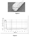
- the optical spectrum analyzer (OSA) output for one of the measured exemplary fiber samples is shown in FIG. 7 .
- the measured beat length range for 5 different fiber samples of the FIG. 3 fiber was between 21.4mm and 23.9mm.
- the same level of birefringence as that achieved by already known fibers may now be created by using lower dopants and/or by creating smaller stress levels resulting from the pairs of the stress rods, because the stresses created in orthogonal directions have opposite signs.
- the lower boron doping level can make PM fiber manufacturing easier (fiber drawing stage).
- one pair of stress rods utilizes a higher level of B (same level as that used in conventional PM fiber with B-doped stress rods)
- a larger amount of birefringence than achievable by conventional fiber can now be achieved due to the stress differential created by the two sets of stress rods 13A and 13B .
- the stress rods 13A and 13B have different CTE coefficients, which creates different signs for stress induced birefringence in the fiber core area by each pair of stress rods.
- the total effective birefringence value may be increased substantially versus birefringence of commercially available PM fibers, or the same level of birefringence may be obtained with lower level of doping of stress applying rods.
- utilizing stress rods 13A and 13B that have different softening points from one another, and from that of the cladding material can additional birefringence and different stress signs in the fiber core area by each pair of stress rods.
Landscapes
- Chemical & Material Sciences (AREA)
- Engineering & Computer Science (AREA)
- Manufacturing & Machinery (AREA)
- Life Sciences & Earth Sciences (AREA)
- General Life Sciences & Earth Sciences (AREA)
- Geochemistry & Mineralogy (AREA)
- Organic Chemistry (AREA)
- Materials Engineering (AREA)
- Physics & Mathematics (AREA)
- Thermal Sciences (AREA)
- Optics & Photonics (AREA)
- General Physics & Mathematics (AREA)
- Chemical Kinetics & Catalysis (AREA)
- General Chemical & Material Sciences (AREA)
- Glass Compositions (AREA)
- Optical Fibers, Optical Fiber Cores, And Optical Fiber Bundles (AREA)
Abstract
Description
- This application claims the benefit of priority of
US Application Serial No. 12/771,272 filed on April 30, 2010 - The disclosure relates generally to optical waveguide fibers, and more particularly to optical fibers exhibiting single polarization or polarization maintenance properties, and/or high birefringence.
- Optical fiber has become a favorite medium for telecommunications due to its high capacity and immunity to electrical noise. Polarization maintaining (PM) fibers and single polarization (SP) fibers have been widely used to produce linear polarized output in optical systems. These fibers are useful for ultra-high speed transmission systems and are also utilized as couplers' fiber for use with, and connection to, optical components (e.g., lasers, EDFAs, optical instruments, interferometric sensors, and fiber gyroscopes). The single polarization fibers and polarization maintaining fibers can either be active, which means that they are rare earth doped in the fiber core, or passive, which means no rare earth dopants are involved. The polarization characteristic of single polarization fiber means that the fiber propagates one, and only one, of two orthogonally polarized polarizations within a single polarization band while suppressing the other polarization by dramatically increasing its transmission loss.
- Polarization maintaining fibers (also referred to as a polarization retaining fibers) can maintain the input linear polarization on one of two orthogonally oriented axes. These fibers are not single polarization fibers. A common polarization maintaining fiber (referred to as PANDA PM fiber herein) includes, as shown in
FIG. 1 , a circular core 12' surrounded by a pure silica cladding region 14' with two stress-inducing regions 13' (two stress rods) situated therein. Core 12' and the cladding region 14' are formed of conventional materials employed in the formation of optical fibers. The refractive index of the core material is greater than that of the cladding material. Current commercial PANDA type fibers, in order to obtain enough birefringence, have silica cladding and boron doped stress rods that that have greater than 20 wt% B2O3. During the draw process, because of silica cladding, the typical temperatures are grater than 1900°C, and these boron rods become quite fluid (low viscosity) relative to silica. During fiber draw the boron rods tend to "squirt", which need to be corrected by adding complexity to the fiber draw processes, and by drawing fiber at slow speeds. The complexity and slow drawing makes this fiber relatively costly. - The two stress-inducing regions 13' are formed of the same glass material, and thus have the same Coefficients of Thermal Expansion (CTE). The two stress-inducing regions 13' also have composition different from core and cladding materials, and a CTE different from that of cladding material 14'. When such a fiber is drawn, the longitudinally-extending stress-inducing regions 13' will shrink by a different amount than that of the cladding material, whereby fiber core 12' will be put into a state of mechanical strain. Strain induced birefringence (otherwise referred to a stress-induced birefringence) is imparted in the fiber and thereby reduces coupling between the two orthogonally polarized fundamental modes.
- No admission is made that any reference cited herein constitutes prior art. Applicant expressly reserves the right to challenge the accuracy and pertinence of any cited documents.
- The following definitions and terminology are commonly used in the art. Refractive index profile—the refractive index profile is the relationship between the optical fiber material refractive index and the optical fiber radius (as measured from the centerline of the optical fiber) over a selected portion of the fiber.
- Birefringence—birefringence is the difference between the effective refractive indices of the two orthogonally polarized states of the fundamental mode in optical fiber.
- Radii—the radii of the fiber segments are generally defined in terms of points where the index of refraction of the material changes because the material used takes on a different composition. For example, the central core has an inner radius of zero because the first point of the segment is on the centerline. The outer radius of the central core segment is the radius drawn from the waveguide centerline to the last point of the refractive index of the central core having a positive delta. For a segment having a first point away from the centerline, the radius of the waveguide centerline to the location of its first refractive index point is the inner radius of that segment. Likewise, the radius from the waveguide centerline to the location of the last refractive index point of the segment is the outer radius of that segment. For example, a down-doped annular segment surrounding the central core would have an outer radii located at the interface between the annular segment and the cladding.
- Relative refractive index percent Δ%—the term Δ% represents a relative measure of refractive index defined by the equation:

- According to at least some embodiments of the present invention the optical fiber includes:
- (i) a core having a first index of refraction n1;
- (ii) a cladding surrounding the core and having a second index of refraction n2, such that n1>n2, said cladding having at least two stress rods extending longitudinally through the length of said optical fiber, and the stress rods in one set of said least two sets of glass stress rods having different CTEs and/or softening points from CTEs and/or softening points of the other set of stress rods; and
- (iii) wherein the optical fiber supports a single polarization mode or poses polarization maintaining properties within the operating wavelength range.
- Additional features and advantages will be set forth in the detailed description which follows, and in part will be readily apparent to those skilled in the art from the description or recognized by practicing the embodiments as described in the written description and claims hereof, as well as the appended drawings.
- It is to be understood that both the foregoing general description and the following detailed description are merely exemplary, and are intended to provide an overview or framework to understand the nature and character of the claims.
- The accompanying drawings are included to provide a further understanding, and are incorporated in and constitute a part of this specification. The drawings illustrate one or more embodiment(s), and together with the description serve to explain principles and operation of the various embodiments.
-
-
FIG. 1 is a schematic cross-sectional view of a prior art optical fiber; -
FIG. 2 is a schematic of the cross-sectional view of an embodiment of the optical fiber containing a plurality stress rods; -
FIG. 3 illustrates a cross-sectional view of one embodiment of a drawn fiber containing two pairs of stress rods; -
FIG. 4 is the view of an exemplary core-clad blank, with 4 drilled holes; -
FIG. 5 is a plot of the refractive index delta profile of an exemplary core-clad blank; -
FIG. 6 is a schematic of the cross-sectional view of an exemplary core-clad preform; -
FIG. 7 is an OSA output signal used to measure beat length for one of the optical fiber embodiments. - With reference to
FIG. 2 , according to some embodiments, theoptical fiber 10 includes a silica basedcore 12; acladding 14 surrounding thecore 12; and a plurality ofstress rods cladding 14 and extending longitudinally through the length of theoptical fiber 10. Thestress rods stress rods SP fiber 10. For example, in some embodiments, the fiber beat length is about 3 mm to 25 mm at 1550 nm wavelength. Alternatively, or in addition to having differentCTEs stress rods - The
fiber core 12 can either be round or elliptical. When it is round, it is specified by the core radius Rcore. The location and the dimensions of thestress rods stress rod optical fiber 10 ofFIG. 2 there are three delta values (relative to cladding) to be specified, which are delta of the core Δcore, and deltas of the two types of stress rods, ΔrodA (for stress rod(s) 13A), ΔrodB (for stress rod(s) 13B). It is preferable that Δrod and ΔrodA be less 0.1 %. Preferably Δcore is 0.2% to 2%, for example 0.2% to 0.5% or 0.2% to1%. -
Core 12 has a first index of refraction n1. Thecladding 14 has a second index of refraction n2, such that n1>n2. Thestress rods stress rods stress rods cladding 14 and thus have CTEs that are different than the cladding's s CTE. - Preferably, the
optical fiber 10 supports a single polarization mode, or has polarization maintaining properties within the operating wavelength range. For example, if the cladding includes boron, the stress rod(s) 13A may be made of pure silica to create stress in the fiber core in a vertical direction. Alternatively, if thecladding 14 includes 3 wt% B,stress rods 13A may be silica doped with less B (e.g., 0.5 to 2.5 wt % B2O3). B-doped stress rods (rods 13B inFIG. 2 ), for example, may be used to create a stress in a PM fiber core area along horizontal direction, but insuch embodiment rods 13B also have a different amount of B than that incladding 14. For example, if thecladding 14 includes 3 wt% B2O3,rods 13B have more B (e.g., 5 wt% to 25 wt % B2O3). - The two sets of
rods stress rods 13B are made of B doped silica,stress rods 13A may be silica doped with F. Alternatively one set of rods may be made of pure silica, and the other set of stress rods may comprise silica doped with F. Other dopants may also be utilized to create stress on the core in the horizontal direction with opposite sign to the stress in the vertical direction. - In some embodiments one set of stress rods has CTEs of about 5*10E-7/°C, and the CTEs of another set of stress rods are about 5*10E-6/°C. In some embodiments one set of stress rods has CTEs of about 4*10E-7/°C to 1*10E-6/°C (for example 5*10E-7/°C to 8*10E-7/°C and the other set of stress rods has CTES greater than 2*10E-6/°C (for example 4*10E-6/°C to 8*10E-6/°C)
- In some embodiments, the
cladding 14 is silica based glass that is doped with B, and optionally other dopants. In other embodiments thecladding 14 is silica based glass that is doped with Cl (e.g., 0.3 wt% to 1 wt%). In some embodiments the stress applying parts are twostress rods 13A and twostress rods 13B, which have a CTE that is different from that of the cladding material. For example,stress rods 13A comprise silica doped with a higher amount of B than that ofcladding 14 and,stress rods 13A comprise pure silica glass. In some embodiments thecladding 14 is pure silica cladding and one set of stress rods may be doped with B, while the other set of stress rods may be doped with F. Thestress rods stress rods 13A are between 4 and 20 µm, preferably 10 and 20 µm, for example 10 µm, 12 µm or 18 µm. Thestress rods 13A are located outside of thefiber core 12. The radii RrodB of thestress rods 13B are between 4 and 20 µm, preferably between 10 µm and 20 µm, for example, 10 µm, 12 µm or 18 µm Thestress rods 13B are located outside of thefiber core 12. However, thestress rods - In the following embodiments, the relative refractive index delta (Δcore) of the core 12 with respect to the
cladding 14 is between 0.1 % and 2%, more preferably between 0.2% and 1.0%, even more preferably below 0.7% or below 0.5% and most preferably between 0.3% and 0.5% . If thecore 12 is circular, the radius Rcore of thecore 12 is in the range 1-10 µm, more preferably 2.5-8 µm For example, the radius of the core may be 3.8 µm, 4 µm, 4.3 µm, 4.5 µm, or 5 µm The radius of thecladding 14 is between 20 µm and 100 µm, with the preferred values to be around 40 to 62.5 microns. The core 12 in at least some of the embodiments is doped with an index raising material. Preferably, the index raising dopant is GeO2. - According to the some embodiments, the
fiber core 12 includes, Ge 0.2 to 15 wt %; and in the following exemplary embodiments the amount of Ge in the core is about 6 wt%. According to the some embodiments, thecladding 14 includes 97 wt % SiO2 and 3wt. % B. However, the cladding may be, for example pure silica, or silica doped with 1 to 5 wt % of B2O3,, for example 2.5 to 3.5 wt% B2O3,. - Various embodiments will be further clarified by the following examples.
- In this embodiment the
optical fiber 10 is a PM fiber, and thecladding 14 is made of VycorR glass available from Coming Incorporated, of Coming, NY. The VycorR glass is not a pure silica material. It is a silica based glass that includes boron. In this exemplary embodiment, thecladding 14 includes VycorR glass which comprises about 97 wt% silica glass and about 3 wt% B2O3. The optical fiber embodiment ofFIG. 2 utilizes twostress rods 13A, and twostress rods 13B. In this embodiment thestress rods 13B are have an axis of symmetry (Axis B) orthogonal to the one forrods 13A (Axis A). The stresses created by the two pairs of stress rods will generally be applied to thefiber core 12 along these axes. It is noted that a larger number of stress rods may also be utilized. For example, four or sixsmaller stress rods 13A and/or 13B may be used instead of twolarger stress rods -
Stress rods -
FIG. 3 shows a cross section of a drawn fiber, similar to that of the fiber inFIG. 2 . The diameter of theoptical fiber 10 ofFIG. 3 is about 126µm, the core diameter is about 11.4µm, and each stress rod diameter is 32 µm to 33 µm. In this exemplary fiber, the fiber cladding material is 97 wt. % SiO2 and 3 wt. % B. The core material is SiO2 doped with about 6 wt% GeO2 to provide Δcore= 0.25%. One pair of stress rods (rods 13B) is pure silica glass, another pair of stress rods (rods 13A) is SiO2 doped with boron (about 12 wt%). Thestress rods - This comparative example is similar to the
optical fiber 10 ofEmbodiment # 1, because it utilizes the same core 12 (SiO2 doped with about wt% Ge to provide Δcore= 0.25%), cladding 14 (the cladding is silica based glass which comprises about 97 wt% silica glass and about 3 wt% boron), but thestress rods 13A are made of silica doped with the same amount of B (3wt. %) as thecladding 14. Thestress rods 13B of this comparative example are pure silica. The fiber diameter is about 127 µm, the core diameter is about 10.8 µm, and the stress rod diameters are 33 µm to 35 µm. This design does not generate mechanical stresses in the PM fiber core area that have opposite signs. - This embodiment is similar to the Example 1 embodiment. The
optical fiber 10 of Embodiment 2 also includes acladding 14 that is silica based glass that comprises about 97 wt% silica glass and about 3 wt% B2O3, but thestress rods 13A are pure silica. Thestress rods 13A may be located right next to the core, or may be separated from the core by a small distance, with the distance Drod being 0 to 10 µm Thestress rods 13B of this exemplary embodiment are silica doped with P (5 wt%) and are separated further away from the core thanrods 13A (e.g.,rods 13B are separated by at least 10 µm from the core, edge to edge). Thus, the mechanical stress created by the stress rods across the core in the vertical direction (axis A) is of opposite sign from the stress in the horizontal direction (axis B). That is, along one of the axes, the stress is compressive, while along the other axis the stress is tensile. The fiber birefringence of theoptical fiber 10 is the result of the stress differential created by thestress rods stress rods 13A has a different softening point than that of the glass ofstress rods 13B. The final fiber birefringence is the result of the stress differential created by thestress rods - This embodiment is similar to the Example 1 embodiment. The optical fiber of Embodiment 4 includes) silica based
cladding 14 with 0.3 to 1 wt % Cl and thestress rods 13A are B doped silica at least 12 wt % B2O3 (e.g., 12 wt % to 25 wt%), andstress rods 13B are pure silica (i.e., silica with less than 0.1 wt% Cl, and less than 5 ppb of OH, and no other dopants). In this embodiment thecladding 14 and thestress rods 13B have only slightly different CTEs, but the softening points of glass materials for the cladding and of the stress rods are very different, and thus set up a mechanical strain induced birefringence which is significantly greater than the strain resulting from the difference in CTE birefringence of the two materials. This fiber embodiment also has mechanical stresses in fiber core area that have opposite signs. - This embodiment is similar to the Example 1 embodiment. Embodiment 4 fiber utilizes boron doped (3wt%) silica based
cladding 14, but thestress rods 13A are pure silica and thestress rods 13B are silica doped with F and Ge (5 wt % each). In this embodiment thecladding 14 and thestress rods stress rods 13A and thestress rods 13B are also different from one another. Thus the fiber core experiences mechanical strain induced birefringence as well as the strain resulting from the difference in CTE birefringence of the two stress rod materials. This fiber embodiment also has stresses in the fiber core area that have opposite signs. It is noted thatstress rods 13B may be silica doped with F only (i.e., no Ge). - In this embodiment the
optical fiber 10 is similar to that ofEmbodiment 1 fiber, but thecladding 14 is made of silica doped with 0.5 wt% F. The optical fiber embodiment ofFIG. 2 utilizes twostress rods 13A, and twostress rods 13B. In this embodiment thestress rods 13B are have an axis of symmetry (Axis B) orthogonal to the one forrods 13A (Axis A). The stresses created by the two pairs of stress rods will generally be applied to thefiber core 12 along these axes. It is noted that a larger number of stress rods may also be utilized. For example, four or sixsmaller stress rods 13A and/or 13B may be used instead of twolarger stress rods Stress rods optical fiber 10 of about 126µm, the core diameter is about 11.4µm, and each stress rod diameter is 32 µm to 33 µm. In this exemplary fiber, the fiber cladding material is 99.5 wt. % SiO2 and 0.5 wt. % F. The core material is SiO2 doped with about 6 wt% GeO2 to provide Δcore= 0.25%. One pair of stress rods (rods 13B) is pure silica glass, another pair of stress rods (rods 13A) is SiO2 doped with boron (about 12 wt%). Thestress rods - The
optical fiber 10 can be made from a fiber preform, for example, by: (i) providing VycorR glass tube 20 (which will form fiber cladding) with holes 23 for insertion of a plurality of stress rods, and acentral hole 22 for the core rod (FIG. 4 ). After the core rod and the stress rods are inserted into the cladding portion of the preform, the resultant assembly can be re-drawn into a smaller blank, and then drawn into anoptical fiber 10, for example the optical fiber ofFIGs. 2 or 3 . Alternatively, a core-clad preform (also referred to as a core-clad-blank) can be made first, and the holes 23 for receivingstress rods FIG. 5 . In this core-blank embodiment, the clad portion of the blank contained 3 wt % B. Two of the stress rods were made of silica doped with 13 wt % B. The other two stress rods were made of pure silica. The pure silica stress rods (e.g. rods 23B) can be made by chlorine drying silica soot preforms to remove the hydroxyls in the silica soot during the drying step of consolidation process. Then, the silica soot preform has the chlorine removed actively by introducing carbon monoxide or simply leaving it out gas for a period of time (e.g., 2 to 10 hours) at about 1200 °C to passively outgas the chlorine. After the degassing, the soot preform is sintered (sintering step of the consolidation process) in He atmosphere at about 1450°C and redrawn into appropriate size stress rods (e.g.,rods 23B). If the glass tube 20 (corresponding to fiber cladding) is made with Cl doped silica (0.3 to 1 wt% Cl), it can be made similarly to the above described method for making pure silica rods, except the Cl is left on during the sintering step, in order to retain Cl in the glass. - After the
stress rods FIG. 6 ) was drawn under vacuum to produce 125-µm diameter fiber. The draw temperature was between 1875 °C and 1925 °C and the draw speed was between 3 m/s and 7 m/s. The draw tension was 40g for all samples. A resulting exemplary optical fiber cross-section (after the fiber was cut) is illustrated inFIG. 3 (fiber Embodiment 1). The exemplary optical fibers of this embodiment had spectral attenuation of 2.5-4.5 dB/km at 1550 nm and, mode field diameter (MFD) of 9.6-9.9 µm, and polarization beat length of 22-23 mm at 1550 nm wavelength. - Alternatively, rather than making a
tube 20 with holes and subsequently filling the holes with rods, a "bundle approach" for making a preform may be utilized. In this case the opposing rods (e.g. pure silica, boron doped rods and chlorine dope silica rods) are assembled around a core rod and then slipped in a surrounding silica tube and then drawn into fiber. This method will typically result in stress rods with non-circular cross-section. In this fiber the birefringence will be augmented by an additional set of rods of opposite sign. - The polarization beat length was measured using broadband light source, linear polarizer and analyzer at the fiber sample's (about 1 m in length) input and output ends, respectively. The optical spectrum analyzer (OSA) output for one of the measured exemplary fiber samples is shown in
FIG. 7 . Beat length Lb is calculated using the spectral period for the OSA signal Δλ, center wavelength λc (1550nm in our case), and physical length of the sample L:
- The measured beat length range for 5 different fiber samples of the
FIG. 3 fiber was between 21.4mm and 23.9mm. - Advantageously, the same level of birefringence as that achieved by already known fibers may now be created by using lower dopants and/or by creating smaller stress levels resulting from the pairs of the stress rods, because the stresses created in orthogonal directions have opposite signs. The lower boron doping level can make PM fiber manufacturing easier (fiber drawing stage). Alternatively, also advantageously, if one pair of stress rods utilizes a higher level of B (same level as that used in conventional PM fiber with B-doped stress rods), a larger amount of birefringence than achievable by conventional fiber can now be achieved due to the stress differential created by the two sets of
stress rods - Unless otherwise expressly stated, it is in no way intended that any method set forth herein be construed as requiring that its steps be performed in a specific order. Accordingly, where a method claim does not actually recite an order to be followed by its steps or it is not otherwise specifically stated in the claims or descriptions that the steps are to be limited to a specific order, it is no way intended that any particular order be inferred.
- One of advantages of at least some of the embodiments of
optical fiber 10 is that thestress rods stress rods - It will be apparent to those skilled in the art that various modifications and variations can be made without departing from the spirit or scope of the invention. Since modifications, combinations, sub-combinations and variations of the disclosed embodiments incorporating the spirit and substance of the invention may occur to persons skilled in the art, the invention should be construed to include everything within the scope of the appended claims and their equivalents.
Claims (15)
- An optical fiber comprising:(i) a core having a first index of refraction n1;(ii) a cladding surrounding the core and having a second index of refraction n2, such that n1>n2, said cladding having at least two sets of glass stress rods extending longitudinally through the length of said optical fiber, the stress rods in one set of said least two sets of glass stress rods having different CTEs and/or softening points from CTEs and/or softening points of the other set of stress rods; and(iii) wherein said optical fiber supports a single polarization mode or poses polarization maintaining properties within the operating wavelength range.
- The optical fiber of claim 1 wherein at least two of said stress rods in one set of stress rods are made of material different from material for at lest two stress rods of said other set.
- The optical fiber of claim 1, wherein the core has a relative refractive index Δ1 (relative to cladding) such that 0.1%≤Δ1≤2%, and comprises GeO2 6 to 40 wt %; the cladding is silica based glass doped with B; and at least two of the stress rods are either pure silica or are silica doped with F or B.
- The optical fiber of claim 3, wherein the cladding comprises at least one of the following dopants: B2O3: 1 to 5 wt %, F: 0.1 to 2 wt %, Cl: 0.1 to 1 wt%.
- The optical fiber of claim 4, wherein the cladding comprises B2O3, 2.5 to 3.5 wt %, and/or Cl: 0.2 to 0.5 wt%.
- The optical fiber of claim 1, wherein the core has a relative refractive index Δ1 (relative to cladding) such that 0.2%≤Δ1≤2%, and comprises GeO2 6 to 40 wt %; the cladding is silica based glass doped with B; at least two of the stress rods are doped with B in the amount different from that of the cladding, and at least two of the stress rods are pure silica.
- The optical fiber of claim 1, wherein the CTE of at least one of the stress rods is about 5*10E-7/°C, and the CTE of another one of said stress rods is about 5*10E-6/°C.
- The optical fiber of claim 1, wherein two of said stress rods apply compressive force on said core and two of said stress rods apply tensile force on said core.
- The optical fiber of claim 1, wherein two of said stress rods have CTE smaller than that of the cladding, and two of said stress rods have CTE greater than that of the cladding.
- The optical fiber of claim 1, wherein at least two of said stress rods are pure silica rods.
- A method of making a fiber with two sets of stress rods that have different CTEs, said method comprising the step of making a preform with at least four holes for inserting stress applying rods.
- A method of making a fiber with two sets of stress rods that have different CTEs, said method comprising the step of: (i) surrounding a core rod with a plurality of stress applying rods, set plurality of stress applying rods including two sets of rods with different CTEs.
- The method of claim 12 wherein said plurality of rods include a third set of rods with a CTE that is different from said CTEs of said two said stress applying rods.
- A method of making a fiber with three sets of rods that have different softening points from one another, said method comprising the step of: (i) surrounding a core rod with a plurality of stress applying rods, set plurality of stress applying rods including two sets of rods with different softening points.
- The method of claim 14 wherein said plurality of rods include a third set of rods of cladding material, with a softening point that is different from the softening point of either one of said stress applying rods.
Applications Claiming Priority (1)
| Application Number | Priority Date | Filing Date | Title |
|---|---|---|---|
| US12/771,272 US8526773B2 (en) | 2010-04-30 | 2010-04-30 | Optical fiber with differential birefringence mechanism |
Publications (2)
| Publication Number | Publication Date |
|---|---|
| EP2383233A2 true EP2383233A2 (en) | 2011-11-02 |
| EP2383233A3 EP2383233A3 (en) | 2012-02-08 |
Family
ID=44303247
Family Applications (1)
| Application Number | Title | Priority Date | Filing Date |
|---|---|---|---|
| EP11162965A Withdrawn EP2383233A3 (en) | 2010-04-30 | 2011-04-19 | Optical fiber with differential birefringence mechanism |
Country Status (4)
| Country | Link |
|---|---|
| US (1) | US8526773B2 (en) |
| EP (1) | EP2383233A3 (en) |
| JP (1) | JP2011237796A (en) |
| CN (1) | CN102236124A (en) |
Families Citing this family (10)
| Publication number | Priority date | Publication date | Assignee | Title |
|---|---|---|---|---|
| EP3072002B1 (en) * | 2013-11-22 | 2024-05-22 | IMRA America, Inc. | Polarizing and polarization maintaining leakage channel fibers |
| US9658394B2 (en) * | 2014-06-24 | 2017-05-23 | Corning Incorporated | Low attenuation fiber with viscosity matched core and inner clad |
| KR20170129237A (en) * | 2015-03-20 | 2017-11-24 | 코닝 인코포레이티드 | Polarization maintaining optical fiber |
| CN106094102B (en) * | 2016-06-03 | 2018-11-30 | 烽火通信科技股份有限公司 | A kind of insensitive polarization maintaining optical fibre of environment |
| KR20190081829A (en) | 2017-12-29 | 2019-07-09 | 대한광통신 주식회사 | Method for manufacturing polarization maintaining optical fiber |
| KR20200081597A (en) | 2018-12-27 | 2020-07-08 | 대한광통신 주식회사 | Method for manufacturing polarization maintaining optical fiber |
| CN111099820B (en) * | 2019-12-30 | 2022-07-05 | 武汉安扬激光技术股份有限公司 | Preparation method of fine stress bar |
| US12399316B2 (en) * | 2021-12-16 | 2025-08-26 | Intel Corporation | Polarization maintaining fiber with alignment features |
| US20240004152A1 (en) * | 2022-06-30 | 2024-01-04 | Corning Incorporated | Few mode optical fibers with reduced mode coupling and low birefringence |
| US12466758B1 (en) * | 2025-01-15 | 2025-11-11 | Honeywell Federal Manufacturing & Technologies, Llc | Fused materials with mismatched properties |
Family Cites Families (18)
| Publication number | Priority date | Publication date | Assignee | Title |
|---|---|---|---|---|
| US4339173A (en) * | 1975-09-08 | 1982-07-13 | Corning Glass Works | Optical waveguide containing P2 O5 and GeO2 |
| GB2065633B (en) * | 1979-10-25 | 1984-03-21 | Nippon Telegraph & Telephone | Optical transmission fiber and process for producing the same |
| US4415230A (en) * | 1981-03-30 | 1983-11-15 | Corning Glass Works | Polarization retaining single-mode optical waveguide |
| CA1177297A (en) * | 1981-03-30 | 1984-11-06 | Michael G. Blankenship | Polarization retaining single-mode optical fibers and methods of making |
| JPS5992929A (en) | 1982-11-17 | 1984-05-29 | Nippon Telegr & Teleph Corp <Ntt> | Preparation of optical fiber maintaining polarization |
| US4561871A (en) * | 1983-12-27 | 1985-12-31 | Corning Glass Works | Method of making polarization preserving optical fiber |
| JPH0627010B2 (en) | 1985-03-19 | 1994-04-13 | 富士通株式会社 | Method of manufacturing polarization-maintaining optical fiber |
| JPS61228404A (en) * | 1985-04-01 | 1986-10-11 | Sumitomo Electric Ind Ltd | Optical fiber for constant polarized wave |
| JPS6283708A (en) * | 1985-10-08 | 1987-04-17 | Sumitomo Electric Ind Ltd | Constant polarization optical fiber |
| JPS63206710A (en) * | 1987-02-24 | 1988-08-26 | Nippon Telegr & Teleph Corp <Ntt> | Absolute single polarization optical fiber and its production |
| US4810276A (en) * | 1987-08-05 | 1989-03-07 | Corning Glass Works | Forming optical fiber having abrupt index change |
| JP2002214465A (en) | 2001-01-17 | 2002-07-31 | Fujikura Ltd | Polarization-maintaining optical fiber |
| US20040007026A1 (en) * | 2001-06-13 | 2004-01-15 | Tomohiro Ishihara | Glass base material and method of manufacturing glass base material |
| CN1285522C (en) * | 2001-06-13 | 2006-11-22 | 住友电气工业株式会社 | Glass precast rod and method for producing glass precast rod |
| JP2003084160A (en) * | 2001-09-13 | 2003-03-19 | Fujikura Ltd | Polarization-maintaining optical fiber |
| EP1700146B1 (en) | 2003-12-19 | 2013-04-10 | NKT Photonics A/S | Photonic crystal fibres comprising stress elements |
| US7900481B2 (en) * | 2006-05-19 | 2011-03-08 | Corning Incorporated | Method of making an optical fiber |
| EP2174172B1 (en) * | 2007-07-31 | 2017-06-21 | Corning Incorporated | Polarization maintaining and single polarization optical fiber comprising boron-fluorine doped stress members |
-
2010
- 2010-04-30 US US12/771,272 patent/US8526773B2/en not_active Expired - Fee Related
-
2011
- 2011-04-19 EP EP11162965A patent/EP2383233A3/en not_active Withdrawn
- 2011-04-28 JP JP2011100745A patent/JP2011237796A/en active Pending
- 2011-04-29 CN CN2011101172139A patent/CN102236124A/en active Pending
Also Published As
| Publication number | Publication date |
|---|---|
| US20110268399A1 (en) | 2011-11-03 |
| US8526773B2 (en) | 2013-09-03 |
| EP2383233A3 (en) | 2012-02-08 |
| CN102236124A (en) | 2011-11-09 |
| JP2011237796A (en) | 2011-11-24 |
Similar Documents
| Publication | Publication Date | Title |
|---|---|---|
| US8526773B2 (en) | Optical fiber with differential birefringence mechanism | |
| EP2174172B1 (en) | Polarization maintaining and single polarization optical fiber comprising boron-fluorine doped stress members | |
| US10838140B2 (en) | Polarization maintaining optical fiber | |
| US8977095B2 (en) | Polarization maintaining optical fibers with intracore stress mechanisms | |
| US7158705B2 (en) | Optical fiber with birefringence and large mode field diameter | |
| US20160274300A1 (en) | Few-mode optical fiber | |
| US7412142B2 (en) | Optical fiber with plurality of air holes and stress rods | |
| WO2015200191A1 (en) | Low attenuation fiber with viscosity matched core and inner clad | |
| EP1636619B1 (en) | Single polarization optical fiber and system | |
| EP2071369A1 (en) | Holey fiber | |
| US6970632B2 (en) | Solid type single polarization fiber and apparatus | |
| Cho et al. | Study on the fabrication process of polarization maintaining photonic crystal fibers and their optical properties | |
| JP2010169965A (en) | Photonic crystal fiber and manufacturing method of the same | |
| JP4015959B2 (en) | High stress-resistant optical fiber | |
| JP2002277667A (en) | Optical fiber | |
| JP2004501053A (en) | Fused silica based optical waveguide and method of making same | |
| JP2005140857A (en) | Dispersion-flat fiber | |
| JP2004226540A (en) | High stress resistant optical fiber | |
| KR100782475B1 (en) | Manufacturing method of optical fiber base material and optical fiber base material | |
| Tanaka et al. | Fabrication of dispersion controlled and polarization maintaining photonic crystal fiber for high performance systems and devices | |
| Gauthier | Exotic Fibres: Multitude of application—specific optical fibres |
Legal Events
| Date | Code | Title | Description |
|---|---|---|---|
| AK | Designated contracting states |
Kind code of ref document: A2 Designated state(s): AL AT BE BG CH CY CZ DE DK EE ES FI FR GB GR HR HU IE IS IT LI LT LU LV MC MK MT NL NO PL PT RO RS SE SI SK SM TR |
|
| AX | Request for extension of the european patent |
Extension state: BA ME |
|
| PUAI | Public reference made under article 153(3) epc to a published international application that has entered the european phase |
Free format text: ORIGINAL CODE: 0009012 |
|
| PUAL | Search report despatched |
Free format text: ORIGINAL CODE: 0009013 |
|
| AK | Designated contracting states |
Kind code of ref document: A3 Designated state(s): AL AT BE BG CH CY CZ DE DK EE ES FI FR GB GR HR HU IE IS IT LI LT LU LV MC MK MT NL NO PL PT RO RS SE SI SK SM TR |
|
| AX | Request for extension of the european patent |
Extension state: BA ME |
|
| RIC1 | Information provided on ipc code assigned before grant |
Ipc: G02B 6/024 20060101ALI20120102BHEP Ipc: C03B 37/012 20060101AFI20120102BHEP |
|
| STAA | Information on the status of an ep patent application or granted ep patent |
Free format text: STATUS: THE APPLICATION IS DEEMED TO BE WITHDRAWN |
|
| 18D | Application deemed to be withdrawn |
Effective date: 20120809 |