EP2383151B1 - Extendable vehicle rack arrangement. - Google Patents
Extendable vehicle rack arrangement. Download PDFInfo
- Publication number
- EP2383151B1 EP2383151B1 EP10161145.7A EP10161145A EP2383151B1 EP 2383151 B1 EP2383151 B1 EP 2383151B1 EP 10161145 A EP10161145 A EP 10161145A EP 2383151 B1 EP2383151 B1 EP 2383151B1
- Authority
- EP
- European Patent Office
- Prior art keywords
- bar
- load carrier
- rack arrangement
- extendable
- carrier foot
- Prior art date
- Legal status (The legal status is an assumption and is not a legal conclusion. Google has not performed a legal analysis and makes no representation as to the accuracy of the status listed.)
- Active
Links
- 238000006073 displacement reaction Methods 0.000 claims description 25
- 210000002683 foot Anatomy 0.000 description 4
- 239000000463 material Substances 0.000 description 3
- 230000001603 reducing effect Effects 0.000 description 3
- 238000000576 coating method Methods 0.000 description 2
- 239000002783 friction material Substances 0.000 description 2
- 239000011248 coating agent Substances 0.000 description 1
- 238000010276 construction Methods 0.000 description 1
- 230000002452 interceptive effect Effects 0.000 description 1
- 230000001788 irregular Effects 0.000 description 1
- 238000006386 neutralization reaction Methods 0.000 description 1
- 230000003472 neutralizing effect Effects 0.000 description 1
- 239000011359 shock absorbing material Substances 0.000 description 1
- 230000003068 static effect Effects 0.000 description 1
Images


Classifications
-
- B—PERFORMING OPERATIONS; TRANSPORTING
- B60—VEHICLES IN GENERAL
- B60R—VEHICLES, VEHICLE FITTINGS, OR VEHICLE PARTS, NOT OTHERWISE PROVIDED FOR
- B60R9/00—Supplementary fittings on vehicle exterior for carrying loads, e.g. luggage, sports gear or the like
- B60R9/04—Carriers associated with vehicle roof
- B60R9/042—Carriers characterised by means to facilitate loading or unloading of the load, e.g. rollers, tracks, or the like
-
- B—PERFORMING OPERATIONS; TRANSPORTING
- B60—VEHICLES IN GENERAL
- B60R—VEHICLES, VEHICLE FITTINGS, OR VEHICLE PARTS, NOT OTHERWISE PROVIDED FOR
- B60R9/00—Supplementary fittings on vehicle exterior for carrying loads, e.g. luggage, sports gear or the like
- B60R9/04—Carriers associated with vehicle roof
- B60R9/045—Carriers being adjustable or transformable, e.g. expansible, collapsible
Definitions
- the present invention effectively neutralises, or at least reduces, intrinsic forces which can arise in the extendable vehicle rack arrangement during or after attachment to the vehicle. Such intrinsic forces could also arise if cargo is displaced or unevenly positioned on the extendable vehicle rack arrangement. By reducing the intrinsic forces, the risk of damage to the vehicle, such as deformation of parts of the vehicle body, or the risk of stressing the components of the extendable vehicle rack arrangement can be reduced or removed.
- the support bar can be configured to receive and carry a load.
- the support bar thus comprises a load carrying surface. This has been found to be advantageous if an extended load carrying surface is desired as it reduces the wear on the second bar, and any additional bar if present.
- the displaceable load carrying bar can be arranged in working cooperation with an additional bar, similar to the second bar.
- the additional bar can be adapted to extend substantially parallel with the second bar.
- the displaceable load carrying bar can be readily supported by the second and additional bar, preventing a rotational motion of the displaceable load carrying bar around the longitudinal axis of the displaceable load carrying bar.
- the second and the additional bar can both be pivotally attached, or be connected via a compensation joint, to the first and the second load carrier foot, or optionally if present, to a support bar extending between the first and the second load carrier foot.
- the load carrier foot can be connected to a load carrying bar arrangement and can be sold separately from the load carrying bar arrangement if desired.
- Figure 1 shows, from above and in perspective, a vehicle 1 having a roof 2.
- Two extendable roof rack arrangements 10 are attached to the roof 2.
- One of the extendable roof rack arrangements 10 can be used in combination with a standard roof rack arrangement or optionally, as shown in figure 1 , two extendable roof rack arrangements 10 can be used.
- the extendable roof rack arrangement 10 enables a user to displace a displaceable load carrying bar 11 from a retracted position to a displaced position. In the displaced position, a user can easily place the cargo on the displaceable load carrying bar 11 and thereafter retract the displaceable load carrying bar 11 to its retracted position.
- the retracted load carrying surface is the load carrying surface which the extendable roof rack arrangement is intended to have when the vehicle is used, i.e. during transporting. If however the roof rack arrangement 10 is provided with a load carrying bar lock, the roof rack arrangement 10 can be used during transporting even when the load carrying bar 11 is in the displaced position.
- the displaceable load carrying bar 11 comprises a load carrying surface 40 which is adapted to receive the load.
- the extendable roof rack arrangement 10 has a displaced load carrying surface.
- the load carrying surface is substantially constant in the retracted position and in the displaced position. According to an aspect of the invention, the load carrying surface can be increased when the displaceable load carrying bar 11 is in its displaced position.
- the compensation joint 20 could comprise a flexible member, such as a rubber member, which attaches the second bar 12 to the first load carrier foot 3.
- a rubber member could also compensate for intrinsic forces as mentioned above.
- the aperture 21 could thus be formed in the rubber member and the pin 22 extend through the rubber member, permitting both a pivotally displacement and a longitudinal displacement.
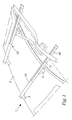
- the extendable roof rack arrangement 10 advantageously comprises a support bar 13, i.e. a third bar, as shown in figure 3 .
- the support bar 13 is fixedly attached to the first and the second load carrier foot 3, 4, at least when the first and the second load carrier foot 3, 4 is in the mounted position.
- the second bar 12 is pivotally arranged to the support bar 13 in the proximity of at least the first load carrier foot 3, but preferably in the proximity of the first and the second load carrier foot 3, 4.
- Figure 3 and 5 further defines the X, Y and Z dimensions used herein.
- the X dimension being equivalent with the width of the displaceable load carrying bar 11, i.e. the forward and rearward direction of the vehicle after the extendable roof rack arrangement 10 has been assembled thereto;
- the Z dimension being equivalent with the longitudinal direction of the displaceable load carrier bar 11, the second bar 12, the support bar 13 and the forth bar 14;
- the Y dimension being equivalent with the height, or the vertical direction of said bars 11, 12, 13, 14.
- the Z-X dimensions form a horizontal plane.
- the second and forth bar 12, 14 comprises an extension in the longitudinal direction, the Z-dimension, somewhat shorter than the support bar 13.
- the displaceable load carrier bar 11 comprises an extension in the longitudinal direction, the Z-dimension, of substantially the same length as the support bar 13. This enables a displacement locking system to be arranged at each end of the extendable roof rack arrangement 10.
- the second and forth bars 12, 14 comprises an extension of less than half the width of the support bar 13, as shown in figure 5 for example.
- the second bar, the support bar 13 and the forth bar 14 can comprise a substantially equal width.
- the second and forth bar 12, 14 are replaced by one bar.
- Such one bar can be e.g. formed from a unitary piece of material or being formed by interconnecting the second and the forth bar 12, 14 at appropriate place or places.
- the displaceable load carrying bar 11 comprises a substantially rectangular cross section.
- the second bar 12 is substantially encompassing the displaceable load carrying bar 11, cross section wise, as seen in figure 6 . Only the load carrying surface is exposed.
- the displaceable load carrying bar 11 comprises at least one C-shaped groove to accommodate attachment means for a load stop, cargo carrier device, such as a roof box, or any other sport or load utility.
- the displaceable load carrying bar 11 comprises a load receiving surface 40 adapted to receive a load for transportation.
- a C-shaped groove is advantageously arranged on the load receiving surface 40 of the displaceable load carrying bar 11.
Landscapes
- Engineering & Computer Science (AREA)
- Mechanical Engineering (AREA)
- Fittings On The Vehicle Exterior For Carrying Loads, And Devices For Holding Or Mounting Articles (AREA)
Description
- The present invention relates to an extendable vehicle rack arrangement having a stationary part and a displaceable part. The stationary part is pivotally connected to at least one of the load carrier feet.
- Car top rack systems, or roof rack arrangements, can be of the static type, having no movable parts, or of the slideable type, having an extendable load carrying surface. An extendable roof rack arrangement is disclosed in the published patent application
WO 2005/44618 - Another vehicle roof rack system is disclosed in the patent publication
AU 2003231667 A1 - Generally there are two different types of load carrier feet used in roof rack systems; clamp rack feet (including rack feets for rails) and fix point feet. A load carrier foot which uses a clamping force imparted between a support surface and a gripping member as primary attachment force is generally of the clamp rack type, and a load carrier foot which are cooperating with pre prepared positions on the vehicle, is generally of a fix point foot.
- During attachment of a clamp rack load carrier foot to the roof of the vehicle, the clamp rack load carrier foot rests on the roof and a grip member engages a ledge on the vehicle. The grip member is thereafter forced in an upwardly by means of attachment means, such as a screw. The attachment means imparts a clamping force between the support surface and the grip member which retains the clamp rack load carrier foot to the roof of the vehicle. A problem with a clamp rack load carrier foot of this type is that this force also imparts the clamp rack load carrier foot with a force component which acts to rotate the clamp rack load carrier foot towards the roof of the vehicle, i.e. each clamp rack load carrier foot tend to force themselves towards each other during attachment. As a consequence, intrinsic forces are formed within the load carrying bar. This could manifest itself by that the stationary part of the roof rack system bends, i.e. forms an arc shape along its length. Such intrinsic forces severely affect the performance of an extendable roof rack system as the extendable part can stick on the arc shaped stationary part. Intrinsic forces imparted via the clamp rack load carrier foot could also arise from misaligned load carrier feet or a wrongly positioned or assembled load carrier foot.
-
US 6428263 B1 discloses a vehicle rack arrangement according to the preamble ofclaim 1. - It is an object of the present invention to partly solve the above mentioned drawbacks, to provide a useful alternative to the above mentioned solutions or to at least reduce the impact of the above mentioned drawbacks. More specifically, this object is met by an extendable vehicle rack arrangement adapted to be attached to a vehicle. The extendable vehicle rack arrangement enables a displacement of a load carrying surface and comprises a first displaceable load carrying bar comprising a first load carrying surface, a second bar arranged in working cooperation with the displaceable load carrying bar.
- A first and a second load carrier foot are attached to the second bar. The displaceable load carrying bar is displaceable with respect to the second bar so as to provide for an extended or displaced load carrying surface after displacement. The second bar is pivotally attached, directly or indirectly, to at least the first load carrier foot, so as to enable a relative displacement of at least the first load carrier foot with respect to the second bar.
- The present invention effectively neutralises, or at least reduces, intrinsic forces which can arise in the extendable vehicle rack arrangement during or after attachment to the vehicle. Such intrinsic forces could also arise if cargo is displaced or unevenly positioned on the extendable vehicle rack arrangement. By reducing the intrinsic forces, the risk of damage to the vehicle, such as deformation of parts of the vehicle body, or the risk of stressing the components of the extendable vehicle rack arrangement can be reduced or removed.
- According to the invention the second bar is pivotally attached, directly or indirectly, to the first and second load carrier foot, so as to enable a relative displacement of the first and second load carrier feet with respect to the second bar. This enables in improved stress and intrinsic force reducing properties.
- According to an aspect of the invention, the second bar has a longitudinal axis, and the first load carrier foot is relatively displaceable in a direction along the first longitudinal axis. This provides a compensation joint between the load carrier foot and the second bar. Both the first and the second load carrier foot can comprise a compensation joint which permits a pivotally displacement and a longitudinal displacement of the second bar with respect to the load carrier feet.
- According to an aspect of the invention, the second bar can comprise a load carrying surface. In this embodiment, the second bar is specifically adapted for receiving a load. The first load carrying surface can be displaceable in both a first and a second longitudinal direction. Optionally the second bar is not configured to receive and carry a load, in which the extendable vehicle rack arrangement comprises a constant load carrying surface, although being displaceable. One advantage of having a constant load carrying surface is that the displaceable load carrying bar can be adapted to extend across substantially the whole length of the extendable vehicle rack arrangement, further enabling the first load carrying surface to be easily reachable and displaceable in a first and a second longitudinal direction. This enables a user to displace the displaceable load carrying bar on either side of the vehicle if desirable.
- According to an aspect of the invention, the extendable vehicle rack arrangement comprises at least one support bar. The at least one support bar extends between the first and second load carrier foot and provide rigidity to the first and the second load carrier foot and is substantially fixedly attached thereto. The support bar is at least substantially fixedly attached to the first and the second load carrier foot, at least when the first and the second load carrier foot is in the mounted position, as defined herein.
- In the embodiments having at least one support bar, the second bar is advantageously pivotally attached to the at least one support bar, so as to enable a relative displacement of the first load carrier foot, or the first and the second load carrier foot, with respect to the second bar. Optionally, the second bar can still be pivotally attached to the first and/or second load carrier foot, while still having a support bar there between.
- The support bar can be configured to receive and carry a load. In an embodiment, the support bar thus comprises a load carrying surface. This has been found to be advantageous if an extended load carrying surface is desired as it reduces the wear on the second bar, and any additional bar if present.
- According to an aspect of the invention, the displaceable load carrying bar can be arranged in working cooperation with an additional bar, similar to the second bar. The additional bar can be adapted to extend substantially parallel with the second bar. The displaceable load carrying bar can be readily supported by the second and additional bar, preventing a rotational motion of the displaceable load carrying bar around the longitudinal axis of the displaceable load carrying bar. The second and the additional bar can both be pivotally attached, or be connected via a compensation joint, to the first and the second load carrier foot, or optionally if present, to a support bar extending between the first and the second load carrier foot.
- In an embodiment, at least one support bar can be arranged between the second and the additional bar. In this case the extendable vehicle rack arrangement comprises a support bar, the additional bar is then referred to as the forth bar, i.e. the additional forth bar. The second and forth bars can be pivotally attached to the at least one support bar to enable a relative displacement of at least the first load carrier foot with respect to said second bar or advantageously to both the first and the second load carrier foot.
- The extendable vehicle rack arrangement is advantageously used when the first and second load carrier foot are of the clamping type load carrier foot having a support surface and a gripping member.
- In general terms, the present invention relates to an extendable vehicle rack arrangement comprising a first and a second load carrier foot and comprising a stationary part attached to said first and second load carrier foot and a displaceable part. The stationary part is pivotally connected to at least one of the load carrier feet. The extendable vehicle rack arrangement is advantageously an extendable vehicle top rack arrangement, even more advantageously an extendable roof rack arrangement.
- According to an aspect of the invention, the invention relates to an extendable load carrying bar arrangement for an extendable vehicle rack arrangement comprising
- a first displaceable load carrying bar comprising a first load carrying surface,
- at least a second bar arranged in working cooperation with the displaceable load carrying bar. The displaceable load carrying bar is displaceable with respect to the second bar so as to provide for an extended or displaced load carrying surface after displacement. The load carrying bar arrangement comprises means for connecting a first and a second load carrier foot at a first and second connection site. The first and second load carrier foot is operable between a dismounted position and a mounted position. At least the first connection site is adapted to connect to the first load carrier foot by means of a pivot connection so as to enable a relative displacement of at least the first load carrier foot with respect to the second bar after assembly and when being in the mounted position.
- The load carrying bar arrangement can be connected to a load carrier foot and can be sold separately from the load carrier feet if desired.
- The extendable load carrying bar arrangement can comprise an additional bar extending substantially parallel with the second bar. Using one or more addition bars, a more rigid construction is achieved. The at least one support bar can be arranged between the second and the additional bar advantageously.
- According to an aspect of the invention, the invention relates to a load carrier foot for an extendable vehicle rack arrangement. The load carrier foot is adapted to be attached to a surface of a vehicle. The load carrier foot comprises a connection site for receiving and connecting to an extendable load carrying bar arrangement to thereby form an extendable vehicle rack arrangement. The load carrier foot being operable between a dismounted position and a mounted position. The load carrier foot is further adapted to connect to the extendable load carrying bar arrangement by means of a pivot connection so as to enable a relative displacement of the load carrier foot with respect to the second bar after assembly and when being in the mounted position.
- The load carrier foot can be connected to a load carrying bar arrangement and can be sold separately from the load carrying bar arrangement if desired.
- The load carrier foot is advantageously of a clamping type load carrier foot having a support surface and a gripping member.
- The present invention will be described in greater detail with reference to the accompanying figures in which;
-
figure 1 shows a schematic view of two extendable vehicle rack arrangements according to the present invention in their extended positions and attached to a vehicle; -
figure 2 shows an extendable vehicle rack arrangements fromfigure 1 seen from the front of the vehicle; -
figure 3 shows an embodiment of the extendable vehicle rack arrangement as seen from the front of the vehicle; -
figure 4 shows the displaceable load carrying bar and the bar arrangement for attachment with the load carrier feet; -
figure 5 a cross section of parts of the bar arrangement and the connection to one of the load carrier feet and; -
figure 6 a cross section of parts of the bar arrangement and the connection to one of the load carrier feet. -
Figure 1 shows, from above and in perspective, avehicle 1 having aroof 2. Two extendableroof rack arrangements 10 are attached to theroof 2. One of the extendableroof rack arrangements 10 can be used in combination with a standard roof rack arrangement or optionally, as shown infigure 1 , two extendableroof rack arrangements 10 can be used. The extendableroof rack arrangement 10 enables a user to displace a displaceableload carrying bar 11 from a retracted position to a displaced position. In the displaced position, a user can easily place the cargo on the displaceableload carrying bar 11 and thereafter retract the displaceableload carrying bar 11 to its retracted position. -
Figure 1 shows how the tworoof rack arrangements 10 are positioned in their displaced position and acycle carrier rack 12 has been placed on the displaceableload carrying bars 11 of theroof rack arrangements 10. - As mentioned, the displaceable
load carrying bar 11 is operable between a retracted position and a displaced position. When the displaceableload carrying bar 11 is in the retracted position, the extendableroof rack arrangement 10 has a retracted load carrying surface, adapted to receive and carry a load. - According to an aspect of the present invention, the retracted load carrying surface is the load carrying surface which the extendable roof rack arrangement is intended to have when the vehicle is used, i.e. during transporting. If however the
roof rack arrangement 10 is provided with a load carrying bar lock, theroof rack arrangement 10 can be used during transporting even when theload carrying bar 11 is in the displaced position. - The displaceable
load carrying bar 11 comprises aload carrying surface 40 which is adapted to receive the load. When the displaceableload carrying bar 11 is in its displaced position, the extendableroof rack arrangement 10 has a displaced load carrying surface. In this embodiment, the load carrying surface is substantially constant in the retracted position and in the displaced position. According to an aspect of the invention, the load carrying surface can be increased when the displaceableload carrying bar 11 is in its displaced position. - The displaced position can be a plurality of different positions enabling a step wise displacement or increase of the load carrying surface, or optionally a continuous displacement or increase of the load carrying surface. The
load carrying bar 11 can be positioned at a minimum displaced position and a maximum displaced position. Between the minimum displaced position and a maximum displaced position, there can be a plurality of positions or an infinite number of positions for the displaceable load carrying bar. - The extendable
roof rack arrangement 10 is attached to theroof 2 of thevehicle 1 using a first and a secondload carrier foot 3, 4. It is of course possible that the extendableroof rack arrangement 10 can be attached to the cargo area of a vehicle, such as the rear cargo compartment or a loading platform of a vehicle. The first and the secondload carrier feet 3, 4 are adapted to be positioned between a dismounted position and a mounted position. In the mounted position, said extendableroof rack arrangement 10 is fixed to thevehicle 1 with at least a sufficient force to drive the vehicle under normal circumstances without risking that the extendableroof rack arrangement 10 comes off. When the first and secondload carrier foot 3, 4 is in the dismounted position, the extendableroof rack arrangement 10 can easily be removed from thevehicle 1 with normal effort. In general terms, an embodiment of the present invention relates to an extendable vehicle rack arrangement comprising a first and a secondload carrier foot 3, 4 and comprising a stationary part attached to said first and secondload carrier foot 3, 4 and a displaceable part. The stationary part is pivotally connected to at least one of theload carrier feet 3, 4. -
Figure 2 shows a schematic view of thevehicle 1 as seen towards the front of the vehicle. -
Figure 2 also shows an embodiment of the present invention in which the extendableroof rack arrangement 10 comprises a displaceableload carrying bar 11. Asecond bar 12 is attached to the first and the secondload carrier foot 3, 4 and extends at least there between. The firstload carrier foot 3 is pivotally attached to thesecond bar 12, as is shown in greater detail infigure 2 . The displaceableload carrier bar 11 is configured to be displaced, in this embodiment to slide along the length of thesecond bar 12, between a retracted position and a displaced position. It should be noted that the displaceableload carrier bar 11 could, in another embodiment, be folded out, or folded down, to a displaced position. - By pivotally connecting the first
load carrier foot 3 to thesecond bar 12, the intrinsic forces between the first and the secondload carrier foot 3, 4, which could arise from force components acting to rotate first and the second the load carrier foot, 3, 4, irregular placed cargo or misaligned load carrier feet providing different attachment forces between theload carrier feet 3, 4, can effectively be neutralized or reduced. By reducing or neutralizing such forces, the displaceableload carrying bar 11 can easily be displaced with respect to thesecond bar 12 without interfering intrinsic forces. Such intrinsic forces could clamp or hinder displacement of a displaceable part. - According to an embodiment of the present invention, both the first and the second
load carrier foot 3, 4 can be pivotally attached to thesecond bar 12. This enables an even better force reduction and/or force neutralization. - As is illustrated in
figure 2 , thesecond bar 12 is pivotally attached to the firstload carrier foot 3 by means of a compensation joint 20. In this embodiment, the compensation joint 20 comprises anaperture 21 and apin 22, which are adapted to compensate for the intrinsic forces between the first and secondload carrier foot 3, 4 if present. Theaperture 21 comprises a longitudinal extension, i.e. an extension parallel with the longitudinal direction of the displaceableload carrying bar 11, so as to compensate for both a pivotal displacement of the firstload carrier foot 3 with respect to thesecond bar 12 and a longitudinal displacement, with respect to thesecond bar 12. Theaperture 21 can however be circular or oval or the like, as long as the above mentioned function is present. - In the shown embodiment in
figure 2 , theaperture 21 is arranged on theload carrier foot 3 and thepin 22 is arranged on thesecond bar 12. In an alternative embodiment, theload carrier foot 3 could comprise a through going pin, or two protruding pins on each side, and thesecond bar 12 could comprise the aperture. - Alternatively, or optionally, the compensation joint 20 could comprise a flexible member, such as a rubber member, which attaches the
second bar 12 to the firstload carrier foot 3. Such rubber member could also compensate for intrinsic forces as mentioned above. Theaperture 21 could thus be formed in the rubber member and thepin 22 extend through the rubber member, permitting both a pivotally displacement and a longitudinal displacement. - The compensation joint 20 is advantageously adapted to prevent the
second bar 12 from displacement in a direction perpendicular to the longitudinal direction of thesecond bar 12, i.e. in a vertical direction indicated infigure 2 as the Y-dimension, while permitting thesecond bar 12 to be displaced in the longitudinal direction of thesecond bar 12 thereby eliminate or reduce intrinsic forces. - In cases where the
load carrier feet 3, 4 is of the type using a clamping force imparted between a support surface and a gripping member as primary attachment force, the extendableroof rack arrangement 10 advantageously comprises asupport bar 13, i.e. a third bar, as shown infigure 3 . In this embodiment, thesupport bar 13 is fixedly attached to the first and the secondload carrier foot 3, 4, at least when the first and the secondload carrier foot 3, 4 is in the mounted position. Thesecond bar 12 is pivotally arranged to thesupport bar 13 in the proximity of at least the firstload carrier foot 3, but preferably in the proximity of the first and the secondload carrier foot 3, 4. -
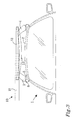
Figure 3 shows a schematic view of the extendableroof rack arrangement 10 after assembly with thevehicle 1. The first and the secondload carrier foot 3, 4 are thus in their mounted positions. As the first and the secondload carrier feet 3, 4 are of the clamping type, as described above, the first and the secondload carrier foot 3, 4 each comprises asupport surface 5 and a grip member 6. Thesupport surface 5 comprises a rubber material so as to provide for a friction and shock absorbing material towards thevehicle 1. During attachment to theroof 2 ofvehicle 1, theload carrier foot 3 rests on thesupport surface 5 whereafter the grip member 6 is forced in an upwardly and inwardly direction, as indicated by the arrow infigure 3 , by a user when mounting the extendableroof rack arrangement 10 using the attachment means, such as a screw or buckle. The attachment means imparts a clamping force between thesupport surface 5 and the gripping member 6 which retains theload carrier foot 3 to theroof 2 of thevehicle 1. - In the shown embodiment, the
second bar 12 is pivotally arranged to thesupport bar 13 in the proximity of the first and the secondload carrier foot 3, 4. At least at the firstload carrier foot 3, thesecond bar 12 is adapted to be displaced in the longitudinal direction of the second bar 12with respect to theload carrier foot 3. This removes the intrinsic forces imparted by the tiltedload carrier feet 3, 4 from the displaceableload carrying bar 11, and thus enables the displaceableload carrying bar 11 to slide on thesecond bar 12 without being subjected to the intrinsic forces. Such intrinsic forces could be bend forces subjected to thesupport bar 13, if present. Some of the intrinsic forces imparted due to the attachment of theload carrier feet 3, 4 are in this case absorbed by thesupport bar 13, which tend to adopt an arc shaped form. Such arc shaped form would severely reduce the ability to displace the displaceableload carrying bar 11 if not compensated by the pivotally attachment of thesecond bar 12 to the first and/or secondload carrier foot 3, 4. - Generally, the extendable roof rack arrangement can thus comprise sliding improvement means to minimize the friction between the first displaceable load carrying bar and the second bar. At least the
second bar 12 can in an embodiment be arranged with sliding improvement means, optionally, both the second and theforth bar 14 can be arranged with sliding improvement means. The sliding improvement means can be means such as ball bearings, low friction coatings, low friction materials, rollers, combinations thereof, or the like. -
Figure 4 shows parts of the extendableroof rack arrangement 10. More specifically,figure 4 shows the displaceableload carrier bar 11 in its displaced position. Thesecond bar 12 and thesupport bar 13 are arranged as described above. A forthbar 14 is arranged to thesupport bar 13 in the same manner as thesecond bar 12. By using twobars support bar 13 and by having both pivotally connected to thesupport bar 13, the displaceableload carrier bar 11 can slide steadily along the second and forth bar 12, 14. Cross directional forces to the longitudinal direction of the displaceableload carrier bar 11 imparted to the displaceableload carrier bar 11 are effectively absorbed in this embodiment. -
Figure 5 shows a cross section of the extendableroof rack arrangement 10 at thecompensation joint 20 of theload carrier foot 3.Figure 5 shows the displaceableload carrier bar 11, thesupport bar 13 and arranged on either side, the second and forth bar 12, 14. Each of the second and forth bar 12, 14 comprises a slidingsurface 30, i.e. a low friction surface. The slidingsurface 30 comprises of a coating, or a sliding material layer, adapted to provide a reduced friction between at least the displaceable load carrier bar 11 I and the second and forth bar 14. It should be noted however, that thesecond bar 12 and asupport bar 13 can be arranged side by side, if no forth bar is present. - As is noticed, both the second and the
forth bar load carrier foot 3 by means of a compensation joint 20. In this embodiment, the compensation joint 20 comprises twoapertures 21 and apin 22, which are adapted to compensate for the intrinsic forces between the first and secondload carrier feet 3, 4 if present. Thesupport bar 13 can thus bend to absorb forces without affecting the sliding ability of the displaceableload carrier bar 11, which slides on the second and forth bar 12, 14. - The displaceable
load carrying bar 11 comprises a substantially C-shaped cross section. This enables the second bar, thesupport bar 13, and theforth bar 14, to be substantially encompassed by the displaceable load carrier bar, cross section wise, as seen infigure 5 . The displaceableload carrier bar 11 comprises at least one C-shaped groove to accommodate attachment means for a load stop, cargo carrier device, such as a roof box, or any other sport or load utility. As shown infigure 5 , the displaceableload carrier bar 11 comprises aload receiving surface 40 adapted to receive a load for transportation. For example, a C-shaped groove is advantageously arranged on theload receiving surface 40 of the displaceableload carrier bar 11. Optionally or additionally, a C-shaped groove can be arranged on therearward side 41 or theforward side 42 of the displaceableload carrying bar 11, theforward side 42 being the side which is intended to be positioned in the forward direction of the vehicle. Optionally all or none of theload receiving surface 40 or the rearward orforward side - As mentioned above, in an embodiment of the present invention, the displaceable
load carrying bar 11 comprises a substantially C-shaped cross section. As such at least thesecond bar 12 can be substantially encompassed by the displaceableload carrying bar 11, and the connection to theload carrier foot 2, 4. This enables the displaceableload carrying bar 11 to be displaced along thesecond bar 12 in both a first and a second longitudinal direction, as is indicated in with the dotted arrow infigure 3 for example. According to an aspect of the present invention, the displaceableload carrying bar 11 can be adapted to be displaced in a first and a second longitudinal direction with respect to the retracted position. This enables a user to, independently of which side of the vehicle he intends to load a cargo onto the firstload carrying surface 40, can displace the displaceableload carrier bar 11 to an extended position to load a cargo. -
Figure 3 and5 further defines the X, Y and Z dimensions used herein. The X dimension being equivalent with the width of the displaceableload carrying bar 11, i.e. the forward and rearward direction of the vehicle after the extendableroof rack arrangement 10 has been assembled thereto; the Z dimension being equivalent with the longitudinal direction of the displaceableload carrier bar 11, thesecond bar 12, thesupport bar 13 and theforth bar 14; the Y dimension being equivalent with the height, or the vertical direction of said bars 11, 12, 13, 14. The Z-X dimensions form a horizontal plane. - The second and forth bar 12, 14 comprises an extension in the longitudinal direction, the Z-dimension, somewhat shorter than the
support bar 13. The displaceableload carrier bar 11 comprises an extension in the longitudinal direction, the Z-dimension, of substantially the same length as thesupport bar 13. This enables a displacement locking system to be arranged at each end of the extendableroof rack arrangement 10. - In an embodiment, the second and forth bars 12, 14 comprises an extension of less than half the width of the
support bar 13, as shown infigure 5 for example. However, the second bar, thesupport bar 13 and theforth bar 14 can comprise a substantially equal width. - In an alternative embodiment the second and forth bar 12, 14 are replaced by one bar. Such one bar can be e.g. formed from a unitary piece of material or being formed by interconnecting the second and the
forth bar - The vehicle could be a land vehicle such as lorry, a van, a car or a trailer, a sea vehicle such as a cargo boat, sailing boat or motor boat, an air vehicle, such as an airplane or helicopter, or the like. Land vehicles are however preferred vehicles.
-
Figure 6 shows a cross section of the extendableroof rack arrangement 10 at thecompensation joint 20 of theload carrier foot 3.Figure 6 shows the displaceableload carrier bar 11 and asecond bar 12. As is noticed, the displaceable load carrying bar is pivotally connected indirectly to the firstload carrier foot 3 by means of a compensation joint 20 to thesecond bar 12. In this embodiment, the compensation joint 20 comprises a first and a second wheel member 20a, 20b, which are adapted to compensate for the intrinsic forces between the first and secondload carrier feet 3, 4 if present. Thesecond bar 12 can thus bend to absorb forces without affecting the sliding ability of the displaceableload carrying bar 11, which can slide on the first and the second wheel member 20a, 20b. - The displaceable
load carrying bar 11 comprises a substantially rectangular cross section. Thesecond bar 12 is substantially encompassing the displaceableload carrying bar 11, cross section wise, as seen infigure 6 . Only the load carrying surface is exposed. The displaceableload carrying bar 11 comprises at least one C-shaped groove to accommodate attachment means for a load stop, cargo carrier device, such as a roof box, or any other sport or load utility. As shown infigure 6 , the displaceableload carrying bar 11 comprises aload receiving surface 40 adapted to receive a load for transportation. For example, a C-shaped groove is advantageously arranged on theload receiving surface 40 of the displaceableload carrying bar 11.
Claims (13)
- An extendable vehicle rack arrangement (10) adapted to carry a cargo on a vehicle (1), said extendable vehicle rack arrangement (10) comprising;- a displaceable load carrying bar (11) comprising a first load carrying surface (40), said displaceable load carrying bar (11) being operable between a retracted position, in which said load carrying surface (11) is a retracted load carrying surface (11), and a displaced position,- a second bar (12, 14) arranged in working cooperation with said displaceable load carrying bar (11),- a first and a second load carrier foot (3, 4) arranged to said second bar (12, 14) and adapted to be attached to a surface (2) of said vehicle (1),said displaceable load carrying bar (11) being displaceable with respect to said second bar (12, 14) so as to provide for an extended or displaced load carrying surface (40) after displacement,characterized in that
said second bar (12, 14) is pivotally connected, directly or indirectly, to at least said first load carrier foot (3), so as to enable a relative displacement of at least said first load carrier foot (3) with respect to said second bar (12, 14). - The extendable vehicle rack arrangement (10) according to claim 1, wherein said second bar (12, 14) is pivotally attached, directly or indirectly, to said first and second load carrier foot (3, 4), so as to enable a relative displacement of said first and second load carrier foot (3, 4) with respect to said second bar (12, 14).
- The extendable vehicle rack arrangement (10) according to claim 1 or 2, wherein said second bar (12, 14) has a longitudinal axis (Z), and that said first load carrier foot (3) is further relatively displaceable in a direction along said first longitudinal axis (Z).
- The extendable vehicle rack arrangement (10) according to any preceding claims, wherein said extendable vehicle rack arrangement (10) comprises at least one support bar (13), said at least one support bar (13) extends between said first and second load carrier foot (3, 4).
- The extendable vehicle rack arrangement (10) according to claim 4, wherein said at least one support bar (13) is substantially fixedly attached to said first and second load carrier foot (3, 4).
- The extendable vehicle rack arrangement (10) according to claim 5, wherein said second bar (12, 14) is pivotally attached to said at least one support bar (13), so as to enable a relative displacement of at least said first load carrier foot (3) with respect to said second bar (12, 14).
- The extendable vehicle rack arrangement (10) according to claim 6, wherein said second bar (12, 14) is pivotally attached to said first load carrier foot (3), or to said first and second load carrier foot (3, 4), so as to enable a relative displacement of at least said first load carrier foot (3) with respect to said second bar (12, 14).
- The extendable vehicle rack arrangement (10) according to any preceding claims, wherein said extendable roof rack arrangement (10) comprises an additional bar (14) extending substantially parallel with said second bar (12).
- The extendable vehicle rack arrangement (10) according to claim 8, wherein said at least one support bar (13) is arranged between said second and additional forth bar (12, 14).
- The extendable vehicle rack arrangement (10) according to claim 9, wherein said second and forth bars (12, 14) are pivotally attached to said at least one support bar (13).
- The extendable vehicle rack arrangement (10) according to any preceding claims, wherein said first and second load carrier foot (3, 4) are of a clamping type load carrier foot (3, 4) having a support surface (5) and a gripping member (6).
- The extendable vehicle rack arrangement (10) according to any preceding claims, wherein said surface (2) of said vehicle (1) is a roof (2) and that said extendable vehicle rack arrangement (10) is an extendable roof rack arrangement (10).
- The extendable vehicle rack arrangement (10) according to any preceding claims, wherein said first and said second load carrier foot (3, 4) are separate components of said extendable vehicle rack arrangement (10) and can be attached and detached from said extendable vehicle rack arrangement (10).
Priority Applications (5)
| Application Number | Priority Date | Filing Date | Title |
|---|---|---|---|
| EP10161145.7A EP2383151B1 (en) | 2010-04-27 | 2010-04-27 | Extendable vehicle rack arrangement. |
| AU2011246544A AU2011246544B2 (en) | 2010-04-27 | 2011-04-20 | Extendable vehicle rack arrangement |
| US13/643,711 US9162629B2 (en) | 2010-04-27 | 2011-04-20 | Extendable vehicle rack arrangement |
| PCT/EP2011/056340 WO2011134868A1 (en) | 2010-04-27 | 2011-04-20 | Extendable vehicle rack arrangement |
| CN201180030952.2A CN102958755B (en) | 2010-04-27 | 2011-04-20 | Extendible vehicles rack is arranged |
Applications Claiming Priority (1)
| Application Number | Priority Date | Filing Date | Title |
|---|---|---|---|
| EP10161145.7A EP2383151B1 (en) | 2010-04-27 | 2010-04-27 | Extendable vehicle rack arrangement. |
Publications (2)
| Publication Number | Publication Date |
|---|---|
| EP2383151A1 EP2383151A1 (en) | 2011-11-02 |
| EP2383151B1 true EP2383151B1 (en) | 2013-10-30 |
Family
ID=42710646
Family Applications (1)
| Application Number | Title | Priority Date | Filing Date |
|---|---|---|---|
| EP10161145.7A Active EP2383151B1 (en) | 2010-04-27 | 2010-04-27 | Extendable vehicle rack arrangement. |
Country Status (5)
| Country | Link |
|---|---|
| US (1) | US9162629B2 (en) |
| EP (1) | EP2383151B1 (en) |
| CN (1) | CN102958755B (en) |
| AU (1) | AU2011246544B2 (en) |
| WO (1) | WO2011134868A1 (en) |
Families Citing this family (5)
| Publication number | Priority date | Publication date | Assignee | Title |
|---|---|---|---|---|
| EP2383151B1 (en) | 2010-04-27 | 2013-10-30 | Thule Sweden AB | Extendable vehicle rack arrangement. |
| US20160159290A1 (en) * | 2014-12-05 | 2016-06-09 | Artin Tamaddon-Dallal | Collapsible rack system for a pick up truck |
| US10780837B2 (en) * | 2016-12-14 | 2020-09-22 | Yakima Products, Inc. | Vehicle rack with loading apparatus |
| CN110997413A (en) * | 2017-01-09 | 2020-04-10 | 勾弗莱特拉克有限公司 | Improvements in or relating to bicycle carrier supports |
| CN107472156B (en) * | 2017-08-17 | 2020-06-30 | 惠安德尔美机械有限公司 | Special article hanging device for SUV (sports utility vehicle) type |
Family Cites Families (15)
| Publication number | Priority date | Publication date | Assignee | Title |
|---|---|---|---|---|
| EP0433495A1 (en) * | 1989-12-15 | 1991-06-26 | Madige S.R.L. | Adjustable bar for luggage racks, ski racks, anything carrying racks and the like |
| US5071050A (en) * | 1990-08-02 | 1991-12-10 | Masco Industries, Inc. | Pivotable cross bar and stanchion connection |
| US5201911A (en) * | 1991-09-26 | 1993-04-13 | Douglas Lee | Mount for bicycle rack |
| JPH09510935A (en) * | 1994-01-26 | 1997-11-04 | アドヴァンスド アクセサリー システムズ リミテッド ライアビリティー カンパニー | Goods carrier |
| US5421495A (en) * | 1994-04-12 | 1995-06-06 | Inovative Bycicle Design Inc. | Vehicle roof rack |
| IT1279544B1 (en) * | 1995-02-17 | 1997-12-16 | Mauro Zona | LUGGAGE RACK FOR MOTOR VEHICLES. |
| US5884824A (en) * | 1996-07-23 | 1999-03-23 | Spring, Jr.; Joseph N. | Equipment transport rack for vehicles providing improved loading accessibility |
| US5782391A (en) * | 1996-11-22 | 1998-07-21 | Cretcher; Gary S. | Vehicle roof rack loading mechanism |
| US5988470A (en) * | 1998-02-09 | 1999-11-23 | Siciliano; Paul | Quick release and car roof rack system |
| SE9802146L (en) * | 1998-06-16 | 1999-11-01 | Mont Blanc Ind Ab | Cargo carrier |
| US6428263B1 (en) * | 2000-07-06 | 2002-08-06 | Thomas Schellens | Vehicular rooftop load elevating device |
| NZ520043A (en) | 2002-08-09 | 2005-04-29 | Hubco Ind Ltd | Vehicle roof rack |
| WO2005044618A2 (en) | 2003-11-05 | 2005-05-19 | Watermark Paddlesports, Inc. | Extendable crossbar system |
| US20070039985A1 (en) * | 2005-08-19 | 2007-02-22 | Charles Warren | Roof rack concept for passenger vehicles, incorporating reconfigurable, multipurpose storage roof for improved aerodynamics and aesthetics |
| EP2383151B1 (en) | 2010-04-27 | 2013-10-30 | Thule Sweden AB | Extendable vehicle rack arrangement. |
-
2010
- 2010-04-27 EP EP10161145.7A patent/EP2383151B1/en active Active
-
2011
- 2011-04-20 WO PCT/EP2011/056340 patent/WO2011134868A1/en active Application Filing
- 2011-04-20 US US13/643,711 patent/US9162629B2/en active Active
- 2011-04-20 AU AU2011246544A patent/AU2011246544B2/en not_active Ceased
- 2011-04-20 CN CN201180030952.2A patent/CN102958755B/en not_active Expired - Fee Related
Also Published As
| Publication number | Publication date |
|---|---|
| US9162629B2 (en) | 2015-10-20 |
| US20130206802A1 (en) | 2013-08-15 |
| AU2011246544B2 (en) | 2014-04-03 |
| CN102958755A (en) | 2013-03-06 |
| WO2011134868A1 (en) | 2011-11-03 |
| EP2383151A1 (en) | 2011-11-02 |
| CN102958755B (en) | 2016-05-11 |
Similar Documents
| Publication | Publication Date | Title |
|---|---|---|
| EP2383151B1 (en) | Extendable vehicle rack arrangement. | |
| EP2995505B1 (en) | Vehicular rack having modular design with outside handle and quick release | |
| US7712812B2 (en) | Flatbed extender system for a vehicle | |
| US5669654A (en) | Extendable rear gate for vehicle cargo bed | |
| EP2172368B1 (en) | System and method for vehicle article carrier having stowable cross bars | |
| AU2011246544A1 (en) | Extendable vehicle rack arrangement | |
| CN109249865B (en) | Bicycle rack mounted on vehicle | |
| EP2208644B1 (en) | Load carrier foot | |
| US9156411B2 (en) | Vehicle roof storage system | |
| EP3081417B1 (en) | Tonneau cover having tensioning system with cables | |
| WO2009071055A3 (en) | Motor vehicle seat | |
| EP2380777A1 (en) | Load carrier foot and a vehicle rack arrangement for a vehicle. | |
| CN104271429B (en) | Automotive steering post | |
| US20100193555A1 (en) | Auxiliary support device for a vehicle | |
| MX2015000743A (en) | Deploy and extend step pad. | |
| US20020014504A1 (en) | Load-carrier with movable carriage for automotive vehicle | |
| US11447074B2 (en) | Laterally extensible accessible vehicle cargo rack | |
| US20220017020A1 (en) | Multi-use adaptable hitch-mounted load support system | |
| US8662534B2 (en) | Rollover protection system with rollover body which can be pivoted out | |
| EP2777989A1 (en) | Powered bicycle racking system | |
| US20120074187A1 (en) | Deployable roof rack system | |
| US8267292B2 (en) | Load carrier for vehicle roof | |
| US20020070254A1 (en) | Moveable stowage assembly | |
| US20110002763A1 (en) | Motor vehicle having an extendable ramp | |
| US9539947B1 (en) | Running board bracket |
Legal Events
| Date | Code | Title | Description |
|---|---|---|---|
| AK | Designated contracting states |
Kind code of ref document: A1 Designated state(s): AT BE BG CH CY CZ DE DK EE ES FI FR GB GR HR HU IE IS IT LI LT LU LV MC MK MT NL NO PL PT RO SE SI SK SM TR |
|
| AX | Request for extension of the european patent |
Extension state: AL BA ME RS |
|
| 17P | Request for examination filed |
Effective date: 20111011 |
|
| PUAI | Public reference made under article 153(3) epc to a published international application that has entered the european phase |
Free format text: ORIGINAL CODE: 0009012 |
|
| 17Q | First examination report despatched |
Effective date: 20120820 |
|
| GRAP | Despatch of communication of intention to grant a patent |
Free format text: ORIGINAL CODE: EPIDOSNIGR1 |
|
| RIC1 | Information provided on ipc code assigned before grant |
Ipc: B60R 9/045 20060101AFI20130515BHEP Ipc: B60R 9/04 20060101ALN20130515BHEP |
|
| INTG | Intention to grant announced |
Effective date: 20130603 |
|
| GRAS | Grant fee paid |
Free format text: ORIGINAL CODE: EPIDOSNIGR3 |
|
| GRAA | (expected) grant |
Free format text: ORIGINAL CODE: 0009210 |
|
| AK | Designated contracting states |
Kind code of ref document: B1 Designated state(s): AT BE BG CH CY CZ DE DK EE ES FI FR GB GR HR HU IE IS IT LI LT LU LV MC MK MT NL NO PL PT RO SE SI SK SM TR |
|
| REG | Reference to a national code |
Ref country code: GB Ref legal event code: FG4D |
|
| REG | Reference to a national code |
Ref country code: CH Ref legal event code: EP |
|
| REG | Reference to a national code |
Ref country code: AT Ref legal event code: REF Ref document number: 638374 Country of ref document: AT Kind code of ref document: T Effective date: 20131115 |
|
| REG | Reference to a national code |
Ref country code: IE Ref legal event code: FG4D |
|
| REG | Reference to a national code |
Ref country code: DE Ref legal event code: R096 Ref document number: 602010011286 Country of ref document: DE Effective date: 20131219 |
|
| REG | Reference to a national code |
Ref country code: SE Ref legal event code: TRGR |
|
| REG | Reference to a national code |
Ref country code: NL Ref legal event code: VDEP Effective date: 20131030 |
|
| REG | Reference to a national code |
Ref country code: AT Ref legal event code: MK05 Ref document number: 638374 Country of ref document: AT Kind code of ref document: T Effective date: 20131030 |
|
| REG | Reference to a national code |
Ref country code: LT Ref legal event code: MG4D |
|
| PG25 | Lapsed in a contracting state [announced via postgrant information from national office to epo] |
Ref country code: IS Free format text: LAPSE BECAUSE OF FAILURE TO SUBMIT A TRANSLATION OF THE DESCRIPTION OR TO PAY THE FEE WITHIN THE PRESCRIBED TIME-LIMIT Effective date: 20140228 Ref country code: NO Free format text: LAPSE BECAUSE OF FAILURE TO SUBMIT A TRANSLATION OF THE DESCRIPTION OR TO PAY THE FEE WITHIN THE PRESCRIBED TIME-LIMIT Effective date: 20140130 Ref country code: BE Free format text: LAPSE BECAUSE OF FAILURE TO SUBMIT A TRANSLATION OF THE DESCRIPTION OR TO PAY THE FEE WITHIN THE PRESCRIBED TIME-LIMIT Effective date: 20131030 Ref country code: FI Free format text: LAPSE BECAUSE OF FAILURE TO SUBMIT A TRANSLATION OF THE DESCRIPTION OR TO PAY THE FEE WITHIN THE PRESCRIBED TIME-LIMIT Effective date: 20131030 Ref country code: LT Free format text: LAPSE BECAUSE OF FAILURE TO SUBMIT A TRANSLATION OF THE DESCRIPTION OR TO PAY THE FEE WITHIN THE PRESCRIBED TIME-LIMIT Effective date: 20131030 Ref country code: NL Free format text: LAPSE BECAUSE OF FAILURE TO SUBMIT A TRANSLATION OF THE DESCRIPTION OR TO PAY THE FEE WITHIN THE PRESCRIBED TIME-LIMIT Effective date: 20131030 Ref country code: HR Free format text: LAPSE BECAUSE OF FAILURE TO SUBMIT A TRANSLATION OF THE DESCRIPTION OR TO PAY THE FEE WITHIN THE PRESCRIBED TIME-LIMIT Effective date: 20131030 |
|
| PG25 | Lapsed in a contracting state [announced via postgrant information from national office to epo] |
Ref country code: LV Free format text: LAPSE BECAUSE OF FAILURE TO SUBMIT A TRANSLATION OF THE DESCRIPTION OR TO PAY THE FEE WITHIN THE PRESCRIBED TIME-LIMIT Effective date: 20131030 Ref country code: ES Free format text: LAPSE BECAUSE OF FAILURE TO SUBMIT A TRANSLATION OF THE DESCRIPTION OR TO PAY THE FEE WITHIN THE PRESCRIBED TIME-LIMIT Effective date: 20131030 Ref country code: CY Free format text: LAPSE BECAUSE OF FAILURE TO SUBMIT A TRANSLATION OF THE DESCRIPTION OR TO PAY THE FEE WITHIN THE PRESCRIBED TIME-LIMIT Effective date: 20131030 Ref country code: AT Free format text: LAPSE BECAUSE OF FAILURE TO SUBMIT A TRANSLATION OF THE DESCRIPTION OR TO PAY THE FEE WITHIN THE PRESCRIBED TIME-LIMIT Effective date: 20131030 |
|
| PG25 | Lapsed in a contracting state [announced via postgrant information from national office to epo] |
Ref country code: PT Free format text: LAPSE BECAUSE OF FAILURE TO SUBMIT A TRANSLATION OF THE DESCRIPTION OR TO PAY THE FEE WITHIN THE PRESCRIBED TIME-LIMIT Effective date: 20140228 |
|
| PG25 | Lapsed in a contracting state [announced via postgrant information from national office to epo] |
Ref country code: EE Free format text: LAPSE BECAUSE OF FAILURE TO SUBMIT A TRANSLATION OF THE DESCRIPTION OR TO PAY THE FEE WITHIN THE PRESCRIBED TIME-LIMIT Effective date: 20131030 |
|
| REG | Reference to a national code |
Ref country code: DE Ref legal event code: R097 Ref document number: 602010011286 Country of ref document: DE |
|
| PG25 | Lapsed in a contracting state [announced via postgrant information from national office to epo] |
Ref country code: RO Free format text: LAPSE BECAUSE OF FAILURE TO SUBMIT A TRANSLATION OF THE DESCRIPTION OR TO PAY THE FEE WITHIN THE PRESCRIBED TIME-LIMIT Effective date: 20131030 Ref country code: CZ Free format text: LAPSE BECAUSE OF FAILURE TO SUBMIT A TRANSLATION OF THE DESCRIPTION OR TO PAY THE FEE WITHIN THE PRESCRIBED TIME-LIMIT Effective date: 20131030 Ref country code: SK Free format text: LAPSE BECAUSE OF FAILURE TO SUBMIT A TRANSLATION OF THE DESCRIPTION OR TO PAY THE FEE WITHIN THE PRESCRIBED TIME-LIMIT Effective date: 20131030 Ref country code: IT Free format text: LAPSE BECAUSE OF FAILURE TO SUBMIT A TRANSLATION OF THE DESCRIPTION OR TO PAY THE FEE WITHIN THE PRESCRIBED TIME-LIMIT Effective date: 20131030 Ref country code: PL Free format text: LAPSE BECAUSE OF FAILURE TO SUBMIT A TRANSLATION OF THE DESCRIPTION OR TO PAY THE FEE WITHIN THE PRESCRIBED TIME-LIMIT Effective date: 20131030 |
|
| PLBE | No opposition filed within time limit |
Free format text: ORIGINAL CODE: 0009261 |
|
| STAA | Information on the status of an ep patent application or granted ep patent |
Free format text: STATUS: NO OPPOSITION FILED WITHIN TIME LIMIT |
|
| PG25 | Lapsed in a contracting state [announced via postgrant information from national office to epo] |
Ref country code: DK Free format text: LAPSE BECAUSE OF FAILURE TO SUBMIT A TRANSLATION OF THE DESCRIPTION OR TO PAY THE FEE WITHIN THE PRESCRIBED TIME-LIMIT Effective date: 20131030 |
|
| 26N | No opposition filed |
Effective date: 20140731 |
|
| REG | Reference to a national code |
Ref country code: DE Ref legal event code: R097 Ref document number: 602010011286 Country of ref document: DE Effective date: 20140731 |
|
| PG25 | Lapsed in a contracting state [announced via postgrant information from national office to epo] |
Ref country code: MC Free format text: LAPSE BECAUSE OF FAILURE TO SUBMIT A TRANSLATION OF THE DESCRIPTION OR TO PAY THE FEE WITHIN THE PRESCRIBED TIME-LIMIT Effective date: 20131030 Ref country code: LU Free format text: LAPSE BECAUSE OF FAILURE TO SUBMIT A TRANSLATION OF THE DESCRIPTION OR TO PAY THE FEE WITHIN THE PRESCRIBED TIME-LIMIT Effective date: 20140427 |
|
| REG | Reference to a national code |
Ref country code: CH Ref legal event code: PL |
|
| REG | Reference to a national code |
Ref country code: IE Ref legal event code: MM4A |
|
| PG25 | Lapsed in a contracting state [announced via postgrant information from national office to epo] |
Ref country code: LI Free format text: LAPSE BECAUSE OF NON-PAYMENT OF DUE FEES Effective date: 20140430 Ref country code: CH Free format text: LAPSE BECAUSE OF NON-PAYMENT OF DUE FEES Effective date: 20140430 |
|
| PG25 | Lapsed in a contracting state [announced via postgrant information from national office to epo] |
Ref country code: SI Free format text: LAPSE BECAUSE OF FAILURE TO SUBMIT A TRANSLATION OF THE DESCRIPTION OR TO PAY THE FEE WITHIN THE PRESCRIBED TIME-LIMIT Effective date: 20131030 |
|
| PG25 | Lapsed in a contracting state [announced via postgrant information from national office to epo] |
Ref country code: IE Free format text: LAPSE BECAUSE OF NON-PAYMENT OF DUE FEES Effective date: 20140427 |
|
| REG | Reference to a national code |
Ref country code: FR Ref legal event code: PLFP Year of fee payment: 7 |
|
| PG25 | Lapsed in a contracting state [announced via postgrant information from national office to epo] |
Ref country code: MT Free format text: LAPSE BECAUSE OF FAILURE TO SUBMIT A TRANSLATION OF THE DESCRIPTION OR TO PAY THE FEE WITHIN THE PRESCRIBED TIME-LIMIT Effective date: 20131030 |
|
| PG25 | Lapsed in a contracting state [announced via postgrant information from national office to epo] |
Ref country code: SM Free format text: LAPSE BECAUSE OF FAILURE TO SUBMIT A TRANSLATION OF THE DESCRIPTION OR TO PAY THE FEE WITHIN THE PRESCRIBED TIME-LIMIT Effective date: 20131030 |
|
| PG25 | Lapsed in a contracting state [announced via postgrant information from national office to epo] |
Ref country code: BG Free format text: LAPSE BECAUSE OF FAILURE TO SUBMIT A TRANSLATION OF THE DESCRIPTION OR TO PAY THE FEE WITHIN THE PRESCRIBED TIME-LIMIT Effective date: 20131030 Ref country code: GR Free format text: LAPSE BECAUSE OF FAILURE TO SUBMIT A TRANSLATION OF THE DESCRIPTION OR TO PAY THE FEE WITHIN THE PRESCRIBED TIME-LIMIT Effective date: 20140131 |
|
| PG25 | Lapsed in a contracting state [announced via postgrant information from national office to epo] |
Ref country code: TR Free format text: LAPSE BECAUSE OF FAILURE TO SUBMIT A TRANSLATION OF THE DESCRIPTION OR TO PAY THE FEE WITHIN THE PRESCRIBED TIME-LIMIT Effective date: 20131030 Ref country code: HU Free format text: LAPSE BECAUSE OF FAILURE TO SUBMIT A TRANSLATION OF THE DESCRIPTION OR TO PAY THE FEE WITHIN THE PRESCRIBED TIME-LIMIT; INVALID AB INITIO Effective date: 20100427 |
|
| REG | Reference to a national code |
Ref country code: FR Ref legal event code: PLFP Year of fee payment: 8 |
|
| REG | Reference to a national code |
Ref country code: FR Ref legal event code: PLFP Year of fee payment: 9 |
|
| PG25 | Lapsed in a contracting state [announced via postgrant information from national office to epo] |
Ref country code: MK Free format text: LAPSE BECAUSE OF FAILURE TO SUBMIT A TRANSLATION OF THE DESCRIPTION OR TO PAY THE FEE WITHIN THE PRESCRIBED TIME-LIMIT Effective date: 20131030 |
|
| PGFP | Annual fee paid to national office [announced via postgrant information from national office to epo] |
Ref country code: SE Payment date: 20220421 Year of fee payment: 13 Ref country code: GB Payment date: 20220419 Year of fee payment: 13 Ref country code: FR Payment date: 20220427 Year of fee payment: 13 |
|
| P01 | Opt-out of the competence of the unified patent court (upc) registered |
Effective date: 20230528 |
|
| REG | Reference to a national code |
Ref country code: SE Ref legal event code: EUG |
|
| GBPC | Gb: european patent ceased through non-payment of renewal fee |
Effective date: 20230427 |
|
| PG25 | Lapsed in a contracting state [announced via postgrant information from national office to epo] |
Ref country code: GB Free format text: LAPSE BECAUSE OF NON-PAYMENT OF DUE FEES Effective date: 20230427 |
|
| PG25 | Lapsed in a contracting state [announced via postgrant information from national office to epo] |
Ref country code: SE Free format text: LAPSE BECAUSE OF NON-PAYMENT OF DUE FEES Effective date: 20230428 Ref country code: GB Free format text: LAPSE BECAUSE OF NON-PAYMENT OF DUE FEES Effective date: 20230427 Ref country code: FR Free format text: LAPSE BECAUSE OF NON-PAYMENT OF DUE FEES Effective date: 20230430 |
|
| PGFP | Annual fee paid to national office [announced via postgrant information from national office to epo] |
Ref country code: DE Payment date: 20240429 Year of fee payment: 15 |