EP2383068A1 - Laser welding apparatus and method of laser welding - Google Patents
Laser welding apparatus and method of laser welding Download PDFInfo
- Publication number
- EP2383068A1 EP2383068A1 EP10733533A EP10733533A EP2383068A1 EP 2383068 A1 EP2383068 A1 EP 2383068A1 EP 10733533 A EP10733533 A EP 10733533A EP 10733533 A EP10733533 A EP 10733533A EP 2383068 A1 EP2383068 A1 EP 2383068A1
- Authority
- EP
- European Patent Office
- Prior art keywords
- flux
- welded
- objects
- laser beam
- welding
- Prior art date
- Legal status (The legal status is an assumption and is not a legal conclusion. Google has not performed a legal analysis and makes no representation as to the accuracy of the status listed.)
- Withdrawn
Links
- 238000003466 welding Methods 0.000 title claims abstract description 84
- 238000000034 method Methods 0.000 title claims abstract description 22
- 230000004907 flux Effects 0.000 claims abstract description 194
- 238000003825 pressing Methods 0.000 claims abstract description 15
- 239000012530 fluid Substances 0.000 claims abstract description 14
- 239000011347 resin Substances 0.000 claims description 27
- 229920005989 resin Polymers 0.000 claims description 27
- 229920001187 thermosetting polymer Polymers 0.000 claims description 23
- 238000002844 melting Methods 0.000 claims description 6
- 230000008018 melting Effects 0.000 claims description 6
- 239000000126 substance Substances 0.000 claims description 3
- 239000000463 material Substances 0.000 abstract description 9
- 230000000149 penetrating effect Effects 0.000 abstract description 8
- 239000011324 bead Substances 0.000 description 56
- 239000002184 metal Substances 0.000 description 40
- 229910052751 metal Inorganic materials 0.000 description 40
- 230000035515 penetration Effects 0.000 description 23
- 238000010586 diagram Methods 0.000 description 20
- 239000004576 sand Substances 0.000 description 17
- 125000006850 spacer group Chemical group 0.000 description 15
- 239000002893 slag Substances 0.000 description 10
- 230000007547 defect Effects 0.000 description 9
- RYGMFSIKBFXOCR-UHFFFAOYSA-N Copper Chemical compound [Cu] RYGMFSIKBFXOCR-UHFFFAOYSA-N 0.000 description 7
- 239000000919 ceramic Substances 0.000 description 7
- 229910052802 copper Inorganic materials 0.000 description 7
- 239000010949 copper Substances 0.000 description 7
- 230000001678 irradiating effect Effects 0.000 description 7
- 230000006866 deterioration Effects 0.000 description 6
- 239000000945 filler Substances 0.000 description 6
- 239000011521 glass Substances 0.000 description 6
- VYPSYNLAJGMNEJ-UHFFFAOYSA-N Silicium dioxide Chemical compound O=[Si]=O VYPSYNLAJGMNEJ-UHFFFAOYSA-N 0.000 description 5
- 239000004744 fabric Substances 0.000 description 4
- WSFSSNUMVMOOMR-UHFFFAOYSA-N Formaldehyde Chemical compound O=C WSFSSNUMVMOOMR-UHFFFAOYSA-N 0.000 description 3
- -1 Ai2O3 Chemical compound 0.000 description 2
- CPLXHLVBOLITMK-UHFFFAOYSA-N Magnesium oxide Chemical compound [Mg]=O CPLXHLVBOLITMK-UHFFFAOYSA-N 0.000 description 2
- GWEVSGVZZGPLCZ-UHFFFAOYSA-N Titan oxide Chemical compound O=[Ti]=O GWEVSGVZZGPLCZ-UHFFFAOYSA-N 0.000 description 2
- MCMNRKCIXSYSNV-UHFFFAOYSA-N Zirconium dioxide Chemical compound O=[Zr]=O MCMNRKCIXSYSNV-UHFFFAOYSA-N 0.000 description 2
- 229910052681 coesite Inorganic materials 0.000 description 2
- 229910052906 cristobalite Inorganic materials 0.000 description 2
- 239000000377 silicon dioxide Substances 0.000 description 2
- 229910052682 stishovite Inorganic materials 0.000 description 2
- 229910052905 tridymite Inorganic materials 0.000 description 2
- 239000004809 Teflon Substances 0.000 description 1
- 229920006362 Teflon® Polymers 0.000 description 1
- 230000005540 biological transmission Effects 0.000 description 1
- 230000015572 biosynthetic process Effects 0.000 description 1
- WUKWITHWXAAZEY-UHFFFAOYSA-L calcium difluoride Chemical compound [F-].[F-].[Ca+2] WUKWITHWXAAZEY-UHFFFAOYSA-L 0.000 description 1
- 229910001634 calcium fluoride Inorganic materials 0.000 description 1
- 230000015556 catabolic process Effects 0.000 description 1
- 238000001816 cooling Methods 0.000 description 1
- 238000006731 degradation reaction Methods 0.000 description 1
- 230000001627 detrimental effect Effects 0.000 description 1
- 230000000694 effects Effects 0.000 description 1
- 231100001261 hazardous Toxicity 0.000 description 1
- 238000010438 heat treatment Methods 0.000 description 1
- 238000003754 machining Methods 0.000 description 1
- 239000000155 melt Substances 0.000 description 1
- 229920001343 polytetrafluoroethylene Polymers 0.000 description 1
- 239000004810 polytetrafluoroethylene Substances 0.000 description 1
- 238000007781 pre-processing Methods 0.000 description 1
Images





Classifications
-
- B—PERFORMING OPERATIONS; TRANSPORTING
- B23—MACHINE TOOLS; METAL-WORKING NOT OTHERWISE PROVIDED FOR
- B23K—SOLDERING OR UNSOLDERING; WELDING; CLADDING OR PLATING BY SOLDERING OR WELDING; CUTTING BY APPLYING HEAT LOCALLY, e.g. FLAME CUTTING; WORKING BY LASER BEAM
- B23K26/00—Working by laser beam, e.g. welding, cutting or boring
- B23K26/20—Bonding
- B23K26/21—Bonding by welding
- B23K26/24—Seam welding
-
- B—PERFORMING OPERATIONS; TRANSPORTING
- B23—MACHINE TOOLS; METAL-WORKING NOT OTHERWISE PROVIDED FOR
- B23K—SOLDERING OR UNSOLDERING; WELDING; CLADDING OR PLATING BY SOLDERING OR WELDING; CUTTING BY APPLYING HEAT LOCALLY, e.g. FLAME CUTTING; WORKING BY LASER BEAM
- B23K26/00—Working by laser beam, e.g. welding, cutting or boring
- B23K26/20—Bonding
- B23K26/21—Bonding by welding
- B23K26/211—Bonding by welding with interposition of special material to facilitate connection of the parts
-
- B—PERFORMING OPERATIONS; TRANSPORTING
- B23—MACHINE TOOLS; METAL-WORKING NOT OTHERWISE PROVIDED FOR
- B23K—SOLDERING OR UNSOLDERING; WELDING; CLADDING OR PLATING BY SOLDERING OR WELDING; CUTTING BY APPLYING HEAT LOCALLY, e.g. FLAME CUTTING; WORKING BY LASER BEAM
- B23K26/00—Working by laser beam, e.g. welding, cutting or boring
- B23K26/20—Bonding
- B23K26/21—Bonding by welding
- B23K26/24—Seam welding
- B23K26/26—Seam welding of rectilinear seams
-
- B—PERFORMING OPERATIONS; TRANSPORTING
- B23—MACHINE TOOLS; METAL-WORKING NOT OTHERWISE PROVIDED FOR
- B23K—SOLDERING OR UNSOLDERING; WELDING; CLADDING OR PLATING BY SOLDERING OR WELDING; CUTTING BY APPLYING HEAT LOCALLY, e.g. FLAME CUTTING; WORKING BY LASER BEAM
- B23K37/00—Auxiliary devices or processes, not specially adapted for a procedure covered by only one of the other main groups of this subclass
- B23K37/04—Auxiliary devices or processes, not specially adapted for a procedure covered by only one of the other main groups of this subclass for holding or positioning work
- B23K37/0408—Auxiliary devices or processes, not specially adapted for a procedure covered by only one of the other main groups of this subclass for holding or positioning work for planar work
-
- B—PERFORMING OPERATIONS; TRANSPORTING
- B23—MACHINE TOOLS; METAL-WORKING NOT OTHERWISE PROVIDED FOR
- B23K—SOLDERING OR UNSOLDERING; WELDING; CLADDING OR PLATING BY SOLDERING OR WELDING; CUTTING BY APPLYING HEAT LOCALLY, e.g. FLAME CUTTING; WORKING BY LASER BEAM
- B23K37/00—Auxiliary devices or processes, not specially adapted for a procedure covered by only one of the other main groups of this subclass
- B23K37/06—Auxiliary devices or processes, not specially adapted for a procedure covered by only one of the other main groups of this subclass for positioning the molten material, e.g. confining it to a desired area
-
- B—PERFORMING OPERATIONS; TRANSPORTING
- B23—MACHINE TOOLS; METAL-WORKING NOT OTHERWISE PROVIDED FOR
- B23K—SOLDERING OR UNSOLDERING; WELDING; CLADDING OR PLATING BY SOLDERING OR WELDING; CUTTING BY APPLYING HEAT LOCALLY, e.g. FLAME CUTTING; WORKING BY LASER BEAM
- B23K2101/00—Articles made by soldering, welding or cutting
- B23K2101/18—Sheet panels
Definitions
- the present invention relates to a laser welding apparatus and a laser welding method suitable for use in welding large members for ships, bridges, and so on, and in particular, in welding where weld lengths are as long as several tens of meters.
- the measure described above still has a problem in that in the case where the gap is large or the plate thicknesses of the objects to be welded are increased, molten metal drips, causing a reverse side bead, that is, a penetration bead, to excessively protrude into a convex shape and a front surface bead to form a concave shape.
- the dripping of molten metal can be prevented by using a mechanism for holding a penetration bead in arc welding.
- a mechanism for holding a penetration bead include a mechanism using a gas, a mechanism using a metal plate, a mechanism using a ceramic block, a mechanism using glass cloth, and a mechanism using particulate flux.
- the mechanism using a gas has a problem in that the molten metal holding strength is insufficient in the case where a gap is present between the members.
- the mechanism using a metal plate has a problem in that a hazardous component may be mixed in the molten metal, making it necessary to remove the metal plate and so on after the welding work. Further, it has a problem in that it is difficult to bring the metal plate into close contact with the objects to be welded. It also has a problem in that it is necessary to enhance the laser beam penetration power, which requires a welding apparatus with larger output.
- the mechanism using a ceramic block has problems in that the ceramic evaporates due to the penetrating laser beam, causing a defect in the shape of the reverse side bead and detrimental defects, such as blowholes and cracks, in the weld metal due to blow back.
- the mechanism using glass cloth has a problem in that the glass cloth is cut by the penetrating laser beam, causing insufficient holding of the penetration bead. It also has a problem in that gas generated when the glass cloth is cut is mixed into the molten metal, causing defects.
- the mechanism using particulate flux has a problem in that when a penetrating laser beam falls directly onto the particulate flux, gas generated from the particulate flux causes defects, such as blowholes or porosities. It also has the problem of causing defects in which slag generated from the flux is included in the weld metal.
- An example of a welding method using particulate flux includes a welding method using a mechanism in which backing flux, sand (underlay flux), and a hose are layered in this order (an FB method or an RF method), which uses backing flux coated with thermosetting resin. Therefore, this method has a problem in that when the backing flux is directly exposed to a penetrating laser beam, gas is generated from the flux and the thermosetting resin, causing the defects described above.
- FCB method using a mechanism in which backing flux, a copper plate, and a hose are layered in this order from the side of the objects to be welded can suppress the occurrence of defects due to the generated gas described above because the backing flux contains no or little thermosetting resin that generates gas.
- the backing flux is brought into close contact with the objects to be welded by supporting the backing flux with the copper plate and pushing up the backing flux and the copper plate.
- the weld metal is held by the flux and the copper plate. Therefore, welding large components having a long weld line has the problem of a difficulty in pressing the backing flux and the copper plate uniformly along the entire length of the weld line.
- the copper plate is sometimes deformed due to heat caused by welding, thus posing the problem of difficulty in handling.
- the present invention is made to solve the above problems, and it is an object thereof to provide a laser welding apparatus and a laser welding method in which degradation in the quality of a welded portion can be prevented for welding thick-walled materials or a gap portion.
- a laser welding apparatus includes a particulate flux that is pressed against a first side of objects to be welded, which a laser beam irradiates from a second side; and a pushing section that expands by receiving a fluid supplied to push the flux toward the first side of the objects to be welded, wherein the laser beam that has penetrated the objects to be welded dose not pass through the flux.
- the amount of flux heated by the laser beam can be controlled, as compared with a case where the laser beam penetrates the flux. This can therefore control the amount of flux melted when heated, which controls the amount of flux that generates gas, thereby controlling the amount of gas generated. Furthermore, occurrence of a defect in which slag generated from the flux is included in the weld metal can be controlled.
- the particulate flux and the pushing section that expands when supplied with fluid are used, the flux can be uniformly pushed against the objects to be welded even if the weld line is long.
- the objects to be welded are welded by irradiating with a laser beam, the quantity of heat applied to the objects to be welded can be controlled, as compared with arc welding and so on. This can therefore control generation of thermal deformation of the objects to be welded.
- the objects to be welded are welded, with the flux pushed against the first side, the objects to be welded that is melted by the laser beam (that is, molten metal) are caught by the flux even if the plate thicknesses of the objects to be welded are large, thereby preventing it from dripping downward and the penetration bead from becoming an excessively convex shape. Even in the case where the gap portion present between the objects to be welded is welded, the molten metal is caught by the flux, thus allowing welding while adding a filler.
- the flux does not contain thermosetting resin or contain the thermosetting resin at less than or equal to about 2 wt%.
- thermosetting resin contained in the flux since the amount of thermosetting resin contained in the flux is small, the amount of gas generated from the flux when heated can be controlled. That is, since the content of thermosetting resin that generates gas when heated is low, the amount of gas generated from the entire flux can be controlled.
- the flux contains thermosetting resin that has already been made to generate gas in advance.
- thermosetting resin from which gas is previously generated allows the amount of gas generated from the flux to be controlled even if the flux is heated during welding.
- An example of the method for previously generating gas is a method of heating the thermosetting resin.
- a guiding section that guides gas generated from the flux heated by the heat of the laser beam to an unheated region of the flux.
- the shielding section between the pushing section and the flux, that blocks the laser beam.
- This configuration can prevent the pushing section from being irradiated with the laser beam while reducing the amount of flux.
- a driving unit or the like that moves the laser beam and the objects to be welded relative to each other fails, the laser beam may continue to irradiate the same portion. In such a case, this configuration can prevent the laser beam that has penetrated the objects to be welded and the flux from irradiating the pushing section.
- a supporting section between the pushing section and the flux, that is a group of particulate substances and that supports the backing flux.
- This configuration allows the flux to be supported with stability and to be uniformly pressed against the objects to be welded by the supporting section. In particular, this can make it easier to uniformly press the flux against the objects to be welded even if the weld line is long, as compared with the method of supporting the flux with a metal plate.
- a laser welding method includes a placement step of placing objects to be welded on the laser welding apparatus according to any of Claims 1 to 6; a pressing step of pressing the flux against the objects to be welded by supplying fluid to the pressing section; and a welding step of welding the objects to be welded by radiating a laser beam thereto.
- a laser welding method includes a placement step of placing objects to be welded on a particulate flux; a pressing step of pressing the flux against the objects to be welded; and a welding step of performing welding while controlling melting of the flux due to the laser beam that has penetrated the objects to be welded when the laser beam irradiates the objects to be welded.
- the laser welding apparatus and the laser welding method of the present invention even in the case where a laser beam irradiating the objects to be welded falls directly onto the flux penetrating the objects to be welded, the amount of gas generated from the flux and so on can be controlled, thus offering the advantage of preventing the deterioration of the quality of the welded portion. Furthermore, since the objects to be welded are welded, with the flux pushed thereagainst, the objects to be welded that are melted by the laser beam (that is, molten metal) are caught by the flux even if the plate thicknesses of the objects to be welded are large, thereby preventing it from dripping downward and the penetration bead from becoming an excessively convex shape. Therefore, this offers the advantage of preventing the deterioration of the quality of the welded portion.
- FIG. 1 is a schematic diagram illustrating the configuration of the penetration-bead holding apparatus according to this embodiment.
- a penetration-bead holding apparatus (laser welding apparatus) 1 of this embodiment is used to hold a penetration bead B while welding objects to be welded W, which are large structural components of ships and so on, through the use of a laser. For example, it is used to weld the objects to be welded W having a gap G, as shown in Fig. 1 .
- the penetration-bead holding apparatus 1 is provided with a housing 2, flux 3, under-sand (supporting section) 4, and a hose (pushing section) 5.
- the housing 2 supports the flux 3, the under-sand 4, and the hose 5 and is disposed in contact with the objects to be welded W during welding.
- the housing 2 is provided with a groove 21 extending along the gap G between the objects to be welded W (in the direction perpendicular to the plane of Fig. 1 ) and a flange 22 extending from the open ends of the groove 21 along the objects to be welded W.
- the groove 21 accommodates therein the flux 3, the under-sand 4, and the hose 5.
- the flange 22 is a portion that is brought into contact with the objects to be welded W when the penetration-bead holding apparatus 1 is disposed on the objects to be welded W.
- the flux 3 is disposed in a position facing the gap G between the objects to be welded W and comes into contact with dripping molten metal during welding.
- the flux 3 is formed in a particulate form and is disposed to form a layer in the groove 21.
- Examples of the thickness of the layer formed of the flux 3 are within the range from about 2 mm to about 50 mm, and more preferably, within the range from about 5 mm to about 20 mm.
- the thickness of the layer of the flux 3 can be reduced, and in the case where the plate thicknesses of the objects to be welded W are large, the thickness of the layer of the flux 3 needs to be increased.
- the thickness of the layer of the flux 3 it is preferable to adjust the thickness of the layer of the flux 3 depending on the materials of the objects to be welded W, the output of the laser beam which is set on the basis of the plate thickness and the amount by which a laser beam penetrates the objects to be welded W. That is, since the flux 3 is replaced every welding and cannot be reused, increasing the thickness of the layer of the flux 3 more than is necessary will increase the time and labor required to replace the flux 3 and increase an unreusable flux 3. Thus, it is preferable to adjust the thickness of the layer of the flux 3 as appropriate.
- the flux 3 examples include fluxes containing SiO 2 as the main component (for example, fluxes containing about 30 wt% to 50 wt%) with which MgO, ZrO 2 , CaF 2 , TiO 2 , Ai 2 O 3 , CaO, or the like is mixed.
- MgO, ZrO 2 , CaF 2 , TiO 2 , Ai 2 O 3 , CaO, or the like is mixed.
- thermosetting resin the surface of the particulate flux 3 may be coated with thermosetting resin; it is not particularly so limited.
- the flux 3 is coated with thermosetting resin, it is preferable that the flux 3 contain thermosetting resin of less than or equal to about 2 wt%.
- thermosetting resin such as a crosslinked resin or a formaldehyde resin
- thermosetting resin it is not particularly limited.
- the under-sand 4 is disposed between the flux 3 and the hose 5 and supports the flux 3.
- the under-sand 4 may be a known one and is not particularly limited.
- under-sand 4 allows the flux 3 to be supported stably and to be uniformly pressed against the objects to be welded W. In particular, this can make it easier to uniformly press the flux 3 against the objects to be welded W even if the weld line is long, as compared with the method of supporting the flux 3 with a metal plate, such as a copper plate.
- the hose 5 supports the flux 3 and the under-sand 4 and presses the flux 3 against the objects to be welded W by expanding by receiving a supply of fluid, such as a pressurized gas.
- a supply of fluid such as a pressurized gas.
- examples of the pressure of fluid supplied to the hose 5 are within the range from about 19.6 kPa to about 196 kPa (about 0.2 kgf/cm 2 to about 2.0 kgf/cm 2 ), and more preferably, within the range from about 49 kPa to about 98 kPa (about 0.5 kgf/cm 2 to about 1.0 kgf/cm 2 ).
- the hose 5 may be a known one and is not particularly limited.
- reactive-force applying sections 6 are provided such that they sandwich the objects to be welded W with the penetration-bead holding apparatus 1.
- the reactive-force applying sections 6 generate a reactive force against the force generated by the hose 5 and pressing the flux 3 against the objects to be welded W.
- Examples of the configuration of the reactive-force applying sections 6 include a configuration in which magnets attracted to the surfaces of the objects to be welded W on which a laser beam is incident (front surfaces) and the surfaces with which the penetration-bead holding apparatus 1 is brought into contact (back surfaces) are provided, with which a reactive force is applied to the objects to be welded W; a configuration in which a reactive force is applied by placing a heavy object on the front surfaces; and a configuration having a mechanism for pressing the front surfaces.
- the objects to be welded W are disposed at a predetermined position, as shown in Fig. 1 .
- the hose 5 is placed in the groove 21, and the penetration-bead holding apparatus 1 filled with the under-sand 4 and the flux 3 is brought into contact with the objects to be welded W (placement step). Specifically, the penetration-bead holding apparatus 1 is placed such that the flux 3 is pressed along the gap G serving as a weld line.
- a predetermined-pressure fluid is supplied to the hose 5, so that the flux 3 is pressed against the objects to be welded W (pressing step). That is, the hose 5 expands when the predetermined-pressure fluid is supplied to push up the under-sand 4 and the flux 3 toward the objects to be welded W. Thus, the flux 3 is pressed against the objects to be welded.
- the reactive force described above is applied from the reactive-force applying section 6 to the objects to be welded W.
- the reactive force indicates a force against a force with which the flux 3 is pressed against the objects to be welded W.
- a laser beam irradiates the objects to be welded W to weld the objects to be welded W (welding step). At that time, the objects to be welded W irradiated with the laser beam melt into a high-temperature molten metal and fill the gap G.
- the gap G has a large width, so that it is difficult to perform welding whereby the gap is sufficiently filled only by the objects to be welded W, a filler is used. That is, the gap G is filled by melting the filler, for example, by irradiating with a laser beam or employing arc welding in combination therewith in the vicinity of the gap G.
- the flux 3 located in the vicinity of the gap G melts due to the heat of the molten metal and so on and irradiation with a laser beam that has passed through the gap G and a laser beam that has penetrated the molten metal of the objects to be welded W and so on.
- the molten metal that has dripped from the gap G is caught by the melted flux 3.
- the molten metal caught by the flux 3 is solidified with cooling to form the penetration bead B.
- a slag layer formed from the flux 3 is formed on the surface of the thus-formed penetration bead B.
- a laser beam to irradiate the objects to be welded W is adjusted to an output at which it enters the flux 3 to a depth from about 1 mm to about 15 mm.
- the melted flux thickness is set to the order of 15 mm or less by adjusting the distance between the laser beam and the arc.
- the quantity of heat input by the laser beam is controlled so as to be proportional to the plate thicknesses of the objects to be welded W.
- a state in which a laser beam has not passed through the layer of the flux 3 and a state in which it has passed therethrough will be described below.
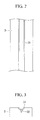
- Fig. 2 is a schematic diagram illustrating the state of the flux through which the laser beam has not passed.
- Fig. 3 is a cross-sectional view illustrating the state of the flux in Fig. 2 .
- Fig. 4 is a picture showing the state of the flux through which the laser beam has not passed.
- solidified slag 31 is formed on the molten metal of the flux 3 through which the laser beam has not passed, in other words, in a region that is in contact with the penetration bead B.
- the solidified slag 31 does not contain bubbles 33, which are formed in the flux 3 through which the laser beam has passed.
- the depth of the recess in the solidified slag 31 is a desired depth. In other words, the recess has a depth at which the penetration bead B can be formed at a desired height.
- a melted layer 32 of the flux 3 which is melted into glass by the laser beam is formed in the layer of the flux 3.
- This melted layer 32 is formed more thinly, as compared with the case where the laser beam has passed through the layer of the flux 3.
- Fig. 5 is a schematic diagram illustrating the state of the flux through which the laser beam has passed.
- Fig. 6 is a cross sectional view illustrating the state of the flux in Fig. 5 .
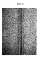
- Figs. 7 and 8 are pictures showing the state of the flux through which the laser beam has passed.
- the solidified slag 31 is formed on the molten metal in the flux 3 through which the laser beam has not passed, in other words, in a region that is in contact with the penetration bead B, as shown in Figs. 5 and 6 .
- the solidified slag 31 contains bubbles 33 due to gas generated from the flux 3 when a laser beam has passed therethrough. Furthermore, the depth of the recess in the solidified slag 31 is deeper than a desired depth. In other words, the recess has a depth at which the penetration bead B can be formed higher than the desired height.
- the melted layer 32 of the flux 3, which is melded by the laser beam, is formed in the layer of the flux 3.
- This melted layer 32 is formed more thickly, as compared with the case where the laser beam has not passed through the layer of the flux 3.
- the amount of gas generated from the flux 3 and so on can be controlled even if the laser beam irradiating the objects to be welded W penetrates the objects to be welded W to fall directly on the flux 3.
- the amount of the flux 3 heated or melted by the laser beam is controlled, as compared with the case where the laser beam penetrates the flux 3. This therefore controls the amount of the flux 3 that generates gas when heated, thus controlling the amount of gas generated. As a result, this can prevent generation of blowholes in the weld metal due to the gas, thereby preventing deterioration in quality.
- the particulate flux 3 and the hose 5 that expands when supplied with fluid are used, the flux 3 can be uniformly pushed against the objects to be welded W even if the weld line is long. As a result, deterioration in the quality of the welded portion, such as dripping of the penetration bead B and excessively convex shape of the penetration bead B, can be prevented
- the objects to be welded W are welded through the use of a laser beam, the quantity of heat applied to the objects to be welded W can be controlled, as compared with arc welding and so on. This can therefore control generation of thermal deformation of the objects to be welded W.
- the objects to be welded W are welded, with the flux 3 pushed against the back thereof, the objects to be welded W melted by the laser beam (that is, molten metal) are caught by the flux 3 even if the plate thicknesses of the objects to be welded W are large, thereby preventing it from dripping downward and the penetration bead B from becoming an excessively convex shape. Even in the case where the gap G portion present in the flux 3 is welded, the molten metal is caught by the flux, thus allowing welding while adding a filler.
- the flux 3 may be one containing thermosetting resin less than or equal to about 2 wt%, as in the above embodiment, or alternatively, the flux 3 may be one containing thermosetting resin from which gas is previously generated by preheating and is not particularly so limited.
- gas may be previously generated by preheating, or alternatively, after the flux 3 is preheated to generate gas, the flux 3 may be spread in the groove 21 of the penetration-bead holding apparatus 1 and is not particularly so limited.
- thermosetting resin from which gas is previously generated allows the amount of gas generated from the flux 3 to be controlled even if the flux 3 is heated during welding. This can therefore prevent generation of blowholes due to the gas in the weld metal, thereby preventing deterioration in quality. Furthermore, even the flux 3 containing much thermosetting resin can be used in the penetration-bead holding apparatus 1 of this embodiment.
- Fig. 9 is a schematic diagram illustrating the configuration of the penetration-bead holding apparatus of this embodiment.
- Fig. 10 is a schematic diagram illustrating the placement positions of spacers in Fig. 9 . Components the same as those in the first embodiment are given the same reference signs and descriptions thereof will be omitted.
- a penetration-bead holding apparatus 101 includes the housing 2, the flux 3, the under-sand 4, the hose 5, and spacers (guiding sections) 107.
- Fig. 11 is a schematic diagram illustrating the configuration of the spacers in Fig. 9 .
- the spacers 107 are cylindrical members made of metal or resin, as shown in Fig. 11 , which guide gas generated from the flux heated by the heat of a laser beam to the unheated region of the flux.
- the spacers 107 are disposed between the flux 3 and the objects to be welded W in a state in which they are embedded in the flux 3.
- the spacers 107 are disposed in an orientation in which the central axis of the cylinder intersects the extending direction of the penetration bead B, more preferably, in a direction perpendicular thereto.
- the spacers 107 are disposed at both sides of the objects to be welded W, with the penetration bead B therebetween, and are disposed along the penetration bead B or the weld line, with a certain distance therebetween.
- Fig. 12 is a schematic diagram illustrating another embodiment of the spacer in Fig. 11 .
- the cylindrical spacers 107 may be used as in the above embodiment, or alternatively, semicylindrical spacers (guiding sections) 107A may be used, as shown in Fig. 12 , and it is not particularly so limited.
- FIG. 13 is a schematic diagram illustrating the configuration of the penetration-bead holding apparatus of this embodiment. Components the same as those in the first embodiment are given the same reference signs and descriptions thereof will be omitted.
- a penetration-bead holding apparatus 201 includes the housing 2, the flux 3, the under-sand 4, the hose 5, and a thin metal plate (shielding section) 207.
- the thin metal plate 207 prevents damage to the hose 5 due to a laser beam and prevents transmission of a laser beam.
- the thin metal plate 207 is a metal plate disposed so as to cover the top of the hose 5 and disposed inside the under-sand 4 in the vicinity of the hose 5 and may be either arcshaped or planar shaped in cross section, as shown in Fig. 13 .
- the above configuration can prevent the hose 5 from being irradiated with the laser beam.
- the laser beam may continue to irradiate the same portion.
- this configuration can prevent the laser beam, that has penetrated the objects to be welded W and the flux 3, from irradiating the hose 5. This allows the hose 5 to continue to press the flux 3 against the objects to be welded W, thus allowing formation of the stable penetration bead B.
- Fig. 14 is a schematic diagram illustrating another example of the penetration-bead holding apparatus in Fig. 13 . Damage to the hose 5 due to a laser beam may be prevented using either the thin metal plate 207, as in the above embodiment, or a ceramic plate (shielding section) 207A instead of the thin metal plate 207, as shown in Fig. 14 , and is not particularly so limited.
- the ceramic plate 207A is a planar plate formed of ceramic so as to cover the top of the hose 5 and is disposed inside the under-sand 4 in the vicinity of the hose 5.
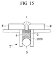
- Fig. 15 is a schematic diagram illustrating yet another example of the penetration-bead holding apparatus in Fig. 13 . Damage to the hose 5 due to a laser beam may be prevented using either the thin metal plate 207, as in the above embodiment, or a particulate shield (shielding section) 207B instead of the thin metal plate 207, as shown in Fig. 15 , and is not particularly so limited.
- the particulate shield 207B is a particulate substance formed of polytetrafluoroethylene (Teflon (a registered trademark)), which is laid between the hose 5 and the under-sand 4 to form a layer.
- Teflon polytetrafluoroethylene
- a layer formed of the under-sand 4 may be formed between the hose 5 and the flux 3, as in the embodiments described above, or a layer formed of the flux 3 may be formed directly on the hose 5, and is not particularly so limited.
Landscapes
- Physics & Mathematics (AREA)
- Optics & Photonics (AREA)
- Engineering & Computer Science (AREA)
- Mechanical Engineering (AREA)
- Plasma & Fusion (AREA)
- Laser Beam Processing (AREA)
- Electric Connection Of Electric Components To Printed Circuits (AREA)
Abstract
Description
- The present invention relates to a laser welding apparatus and a laser welding method suitable for use in welding large members for ships, bridges, and so on, and in particular, in welding where weld lengths are as long as several tens of meters.
- Conventionally, arc welding has been employed for welding large members for ships, bridges, and so on.
When large members are welded by arc welding, deformation occurs in the members due to weld heat input, and the task of correcting these deformations is absolutely essential. - It is known that welding using a high energy beam from a laser or the like (hereinafter expressed as laser welding) is effective as a method for controlling the occurrence of such deformation of members due to welding.
However, this welding method has a problem in that it requires high member alignment precision because it uses a beam focused to a small diameter.
For example, the gap needs to be within about 0.2 mm. - In welding work for ships, bridges, and so on, large members whose weld lines range from several meters to several tens of meters are to be welded, and thus, it is necessary to allow for a gap of at least about 1 mm.
Alternatively, it is necessary to keep the gap within about 0.2 mm by performing preprocessing, such as machining, on large members, followed by welding work. - If a gap is present, the laser beam passes through the gap during the laser welding described above, which makes it impossible to form a bead. Therefore, a measure for merging the gap by supplying a filler into the gap by adding a filler or in conjunction with arc welding is proposed (for example, see Patent Literature 1).
- {PTL} Japanese Unexamined Patent Application, Publication No.
2006-224130 - However, the measure described above still has a problem in that in the case where the gap is large or the plate thicknesses of the objects to be welded are increased, molten metal drips, causing a reverse side bead, that is, a penetration bead, to excessively protrude into a convex shape and a front surface bead to form a concave shape.
- On the other hand, the dripping of molten metal can be prevented by using a mechanism for holding a penetration bead in arc welding. Known examples of the mechanism for holding a penetration bead include a mechanism using a gas, a mechanism using a metal plate, a mechanism using a ceramic block, a mechanism using glass cloth, and a mechanism using particulate flux.
- However, the mechanism using a gas has a problem in that the molten metal holding strength is insufficient in the case where a gap is present between the members.
- The mechanism using a metal plate has a problem in that a hazardous component may be mixed in the molten metal, making it necessary to remove the metal plate and so on after the welding work. Further, it has a problem in that it is difficult to bring the metal plate into close contact with the objects to be welded. It also has a problem in that it is necessary to enhance the laser beam penetration power, which requires a welding apparatus with larger output.
- The mechanism using a ceramic block has problems in that the ceramic evaporates due to the penetrating laser beam, causing a defect in the shape of the reverse side bead and detrimental defects, such as blowholes and cracks, in the weld metal due to blow back.
- The mechanism using glass cloth has a problem in that the glass cloth is cut by the penetrating laser beam, causing insufficient holding of the penetration bead. It also has a problem in that gas generated when the glass cloth is cut is mixed into the molten metal, causing defects.
- The mechanism using particulate flux has a problem in that when a penetrating laser beam falls directly onto the particulate flux, gas generated from the particulate flux causes defects, such as blowholes or porosities. It also has the problem of causing defects in which slag generated from the flux is included in the weld metal.
- An example of a welding method using particulate flux includes a welding method using a mechanism in which backing flux, sand (underlay flux), and a hose are layered in this order (an FB method or an RF method), which uses backing flux coated with thermosetting resin. Therefore, this method has a problem in that when the backing flux is directly exposed to a penetrating laser beam, gas is generated from the flux and the thermosetting resin, causing the defects described above.
- On the other hand, a welding method (FCB method) using a mechanism in which backing flux, a copper plate, and a hose are layered in this order from the side of the objects to be welded can suppress the occurrence of defects due to the generated gas described above because the backing flux contains no or little thermosetting resin that generates gas.
- With the above configuration, the backing flux is brought into close contact with the objects to be welded by supporting the backing flux with the copper plate and pushing up the backing flux and the copper plate. During welding, the weld metal is held by the flux and the copper plate. Therefore, welding large components having a long weld line has the problem of a difficulty in pressing the backing flux and the copper plate uniformly along the entire length of the weld line.
Furthermore, the copper plate is sometimes deformed due to heat caused by welding, thus posing the problem of difficulty in handling. - The present invention is made to solve the above problems, and it is an object thereof to provide a laser welding apparatus and a laser welding method in which degradation in the quality of a welded portion can be prevented for welding thick-walled materials or a gap portion.
- To achieve the above object, the present invention provides the following solutions.
A laser welding apparatus according to a first aspect of the present invention includes a particulate flux that is pressed against a first side of objects to be welded, which a laser beam irradiates from a second side; and a pushing section that expands by receiving a fluid supplied to push the flux toward the first side of the objects to be welded, wherein the laser beam that has penetrated the objects to be welded dose not pass through the flux. - According to the first aspect of the present invention, even if the laser beam irradiating the objects to be welded penetrates the objects to be welded W to fall directly on the flux, melting of the flux can be controlled, and the amount of gas generated from the flux and so on can be controlled.
That is, since the penetrating laser beam is prevented from passing through the flux, the amount of flux heated by the laser beam can be controlled, as compared with a case where the laser beam penetrates the flux. This can therefore control the amount of flux melted when heated, which controls the amount of flux that generates gas, thereby controlling the amount of gas generated.
Furthermore, occurrence of a defect in which slag generated from the flux is included in the weld metal can be controlled. - On the other hand, since the particulate flux and the pushing section that expands when supplied with fluid are used, the flux can be uniformly pushed against the objects to be welded even if the weld line is long.
- Furthermore, since the objects to be welded are welded by irradiating with a laser beam, the quantity of heat applied to the objects to be welded can be controlled, as compared with arc welding and so on. This can therefore control generation of thermal deformation of the objects to be welded.
- Furthermore, since the objects to be welded are welded, with the flux pushed against the first side, the objects to be welded that is melted by the laser beam (that is, molten metal) are caught by the flux even if the plate thicknesses of the objects to be welded are large, thereby preventing it from dripping downward and the penetration bead from becoming an excessively convex shape.
Even in the case where the gap portion present between the objects to be welded is welded, the molten metal is caught by the flux, thus allowing welding while adding a filler. - In the first aspect of the present invention, preferably, the flux does not contain thermosetting resin or contain the thermosetting resin at less than or equal to about 2 wt%.
- With this configuration, since the amount of thermosetting resin contained in the flux is small, the amount of gas generated from the flux when heated can be controlled.
That is, since the content of thermosetting resin that generates gas when heated is low, the amount of gas generated from the entire flux can be controlled. - In the first aspect of the present invention, preferably, the flux contains thermosetting resin that has already been made to generate gas in advance.
- With this configuration, the use of thermosetting resin from which gas is previously generated allows the amount of gas generated from the flux to be controlled even if the flux is heated during welding.
An example of the method for previously generating gas is a method of heating the thermosetting resin. - In the first aspect of the present invention, it is preferable to have a guiding section that guides gas generated from the flux heated by the heat of the laser beam to an unheated region of the flux.
- With this configuration, gas generated from the heated flux is guided to the unheated region of the flux through the guiding section. Since the unheated flux serves as an escape route of the gas, thus suppressing occurrence of problems, such as blowholes.
- In the first aspect of the present invention, it is preferable to have a shielding section, between the pushing section and the flux, that blocks the laser beam.
- This configuration can prevent the pushing section from being irradiated with the laser beam while reducing the amount of flux.
In particular, if a driving unit or the like that moves the laser beam and the objects to be welded relative to each other fails, the laser beam may continue to irradiate the same portion. In such a case, this configuration can prevent the laser beam that has penetrated the objects to be welded and the flux from irradiating the pushing section. - In the first aspect of the present invention, it is preferable to have a supporting section, between the pushing section and the flux, that is a group of particulate substances and that supports the backing flux.
- This configuration allows the flux to be supported with stability and to be uniformly pressed against the objects to be welded by the supporting section. In particular, this can make it easier to uniformly press the flux against the objects to be welded even if the weld line is long, as compared with the method of supporting the flux with a metal plate.
- A laser welding method according to a second aspect of the present invention includes a placement step of placing objects to be welded on the laser welding apparatus according to any of
Claims 1 to 6; a pressing step of pressing the flux against the objects to be welded by supplying fluid to the pressing section; and a welding step of welding the objects to be welded by radiating a laser beam thereto. - According to the second aspect of the present invention, since laser welding is performed using the laser welding apparatus of the present invention described above, deterioration of the quality of the welded portion can be prevented even for welding thick-walled materials or a gap portion.
- A laser welding method according to a third aspect of the present invention includes a placement step of placing objects to be welded on a particulate flux; a pressing step of pressing the flux against the objects to be welded; and a welding step of performing welding while controlling melting of the flux due to the laser beam that has penetrated the objects to be welded when the laser beam irradiates the objects to be welded.
- According to the third aspect of the present invention, since welding is performed while controlling melting of the flux by the laser beam that has penetrated the objects to be welded, even for welding thick-walled materials or a gap portion.
- With the laser welding apparatus and the laser welding method of the present invention, even in the case where a laser beam irradiating the objects to be welded falls directly onto the flux penetrating the objects to be welded, the amount of gas generated from the flux and so on can be controlled, thus offering the advantage of preventing the deterioration of the quality of the welded portion.
Furthermore, since the objects to be welded are welded, with the flux pushed thereagainst, the objects to be welded that are melted by the laser beam (that is, molten metal) are caught by the flux even if the plate thicknesses of the objects to be welded are large, thereby preventing it from dripping downward and the penetration bead from becoming an excessively convex shape. Therefore, this offers the advantage of preventing the deterioration of the quality of the welded portion. -
- {
Fig. 1} Fig. 1 is a schematic diagram illustrating the configuration of a penetration-bead holding apparatus according to a first embodiment of the present invention. - {
Fig. 2} Fig. 2 is a schematic diagram illustrating the state of a flux through which a laser beam has not passed. - {
Fig. 3} Fig. 3 is a cross-sectional view illustrating the state of the flux inFig. 2 . - {
Fig. 4} Fig. 4 is a picture showing the state of the flux through which a laser beam has not passed. - {
Fig. 5} Fig. 5 is a schematic diagram illustrating the state of the flux through which a laser beam has passed. - {
Fig. 6} Fig. 6 is a cross sectional view illustrating the state of the flux inFig. 5 . - {
Fig. 7} Fig. 7 is a picture showing the state of the flux through which a laser beam has passed. - {
Fig. 8} Fig. 8 is a picture showing the state of the flux through which a laser beam has passed. - {
Fig. 9} Fig. 9 is a schematic diagram illustrating the configuration of a penetration-bead holding apparatus of a second embodiment of the present invention. - {
Fig. 10} Fig. 10 is a schematic diagram illustrating the placement positions of spacers inFig. 9 . - {
Fig. 11} Fig. 11 is a schematic diagram illustrating the configuration of the spacers inFig. 9 . - {
Fig. 12} Fig. 12 is a schematic diagram illustrating another embodiment of the spacer inFig. 11 . - {
Fig. 13} Fig. 13 is a schematic diagram illustrating the configuration of a penetration-bead holding apparatus of a third embodiment of the present invention. - {
Fig. 14} Fig. 14 is a schematic diagram illustrating another example of the penetration-bead holding apparatus inFig. 13 . - {
Fig. 15} Fig. 15 is a schematic diagram illustrating yet another example of the penetration-bead holding apparatus inFig. 13 . - A penetration-bead holding apparatus for use in laser welding according to a first embodiment of the present invention will be described with reference to
Figs. 1 to 8 .
Fig. 1 is a schematic diagram illustrating the configuration of the penetration-bead holding apparatus according to this embodiment.
A penetration-bead holding apparatus (laser welding apparatus) 1 of this embodiment is used to hold a penetration bead B while welding objects to be welded W, which are large structural components of ships and so on, through the use of a laser. For example, it is used to weld the objects to be welded W having a gap G, as shown inFig. 1 . - As shown in
Fig. 1 , the penetration-bead holding apparatus 1 is provided with ahousing 2,flux 3, under-sand (supporting section) 4, and a hose (pushing section) 5. - As shown in
Fig. 1 , thehousing 2 supports theflux 3, the under-sand 4, and thehose 5 and is disposed in contact with the objects to be welded W during welding.
Thehousing 2 is provided with agroove 21 extending along the gap G between the objects to be welded W (in the direction perpendicular to the plane ofFig. 1 ) and aflange 22 extending from the open ends of thegroove 21 along the objects to be welded W. - As shown in
Fig. 1 , thegroove 21 accommodates therein theflux 3, the under-sand 4, and thehose 5.
Theflange 22 is a portion that is brought into contact with the objects to be welded W when the penetration-bead holding apparatus 1 is disposed on the objects to be welded W. - As shown in
Fig. 1 , theflux 3 is disposed in a position facing the gap G between the objects to be welded W and comes into contact with dripping molten metal during welding. Theflux 3 is formed in a particulate form and is disposed to form a layer in thegroove 21. - Examples of the thickness of the layer formed of the
flux 3 are within the range from about 2 mm to about 50 mm, and more preferably, within the range from about 5 mm to about 20 mm.
For example, in the case where the plate thicknesses of the objects to be welded W are small, the thickness of the layer of theflux 3 can be reduced, and in the case where the plate thicknesses of the objects to be welded W are large, the thickness of the layer of theflux 3 needs to be increased. - In other words, it is preferable to adjust the thickness of the layer of the
flux 3 depending on the materials of the objects to be welded W, the output of the laser beam which is set on the basis of the plate thickness and the amount by which a laser beam penetrates the objects to be welded W.
That is, since theflux 3 is replaced every welding and cannot be reused, increasing the thickness of the layer of theflux 3 more than is necessary will increase the time and labor required to replace theflux 3 and increase anunreusable flux 3. Thus, it is preferable to adjust the thickness of the layer of theflux 3 as appropriate. - Examples of the
flux 3 include fluxes containing SiO2 as the main component (for example, fluxes containing about 30 wt% to 50 wt%) with which MgO, ZrO2, CaF2, TiO2, Ai2O3, CaO, or the like is mixed.
Thus, it is preferable to use theflux 3 whose slag viscosity, release property, and melting point are adjusted by containing MgO or the like in SiO2. - Furthermore, although this embodiment is described when applied to an example in which the
flux 3 is not coated with thermosetting resin, the surface of theparticulate flux 3 may be coated with thermosetting resin; it is not particularly so limited. - In the case where the
flux 3 is coated with thermosetting resin, it is preferable that theflux 3 contain thermosetting resin of less than or equal to about 2 wt%. - This can control the amount of gas generated from the
flux 3 when heated. That is, since the content of thermosetting resin that generates gas when heated is low, the amount of gas generated from theentire flux 3 can be controlled. This can prevent generation of blowholes due to the gas described above. - A known resin such as a crosslinked resin or a formaldehyde resin can be used as the thermosetting resin; it is not particularly limited.
- As shown in
Fig. 1 , the under-sand 4 is disposed between theflux 3 and thehose 5 and supports theflux 3.
The under-sand 4 may be a known one and is not particularly limited. - The use of the under-
sand 4 in this way allows theflux 3 to be supported stably and to be uniformly pressed against the objects to be welded W. In particular, this can make it easier to uniformly press theflux 3 against the objects to be welded W even if the weld line is long, as compared with the method of supporting theflux 3 with a metal plate, such as a copper plate. - As shown in
Fig. 1 , thehose 5 supports theflux 3 and the under-sand 4 and presses theflux 3 against the objects to be welded W by expanding by receiving a supply of fluid, such as a pressurized gas.
For example, in the case where compressed air is used as the fluid, examples of the pressure of fluid supplied to thehose 5 are within the range from about 19.6 kPa to about 196 kPa (about 0.2 kgf/cm2 to about 2.0 kgf/cm2), and more preferably, within the range from about 49 kPa to about 98 kPa (about 0.5 kgf/cm2 to about 1.0 kgf/cm2). - In the case where the pressure of fluid supplied is too high, a force by which the
flux 3 is pressed against the objects to be welded W becomes excessively strong to form the penetration bead B formed during welding into a concave shape. Furthermore, the gas generated from theflux 3 loses an escape route, which easily causes defects, such as blowholes.
In contrast, in the case where the pressure is low, the penetration bead B formed during welding cannot be prevented from being formed in an excessively convex form. - The
hose 5 may be a known one and is not particularly limited. - Furthermore, as shown in
Fig. 1 , reactive-force applying sections 6 are provided such that they sandwich the objects to be welded W with the penetration-bead holding apparatus 1.
The reactive-force applying sections 6 generate a reactive force against the force generated by thehose 5 and pressing theflux 3 against the objects to be welded W. By providing the reactive-force applying sections 6, deformation and movement of the objects to be welded W due to welding can be suppressed. - Examples of the configuration of the reactive-
force applying sections 6 include a configuration in which magnets attracted to the surfaces of the objects to be welded W on which a laser beam is incident (front surfaces) and the surfaces with which the penetration-bead holding apparatus 1 is brought into contact (back surfaces) are provided, with which a reactive force is applied to the objects to be welded W; a configuration in which a reactive force is applied by placing a heavy object on the front surfaces; and a configuration having a mechanism for pressing the front surfaces. - Next, laser welding using the above-configured penetration-
bead holding apparatus 1 will be described.
To perform laser welding of the objects to be welded W, first, the objects to be welded W are disposed at a predetermined position, as shown inFig. 1 . - Thereafter, the
hose 5 is placed in thegroove 21, and the penetration-bead holding apparatus 1 filled with the under-sand 4 and theflux 3 is brought into contact with the objects to be welded W (placement step).
Specifically, the penetration-bead holding apparatus 1 is placed such that theflux 3 is pressed along the gap G serving as a weld line. - When the penetration-
bead holding apparatus 1 is placed at the predetermined position, a predetermined-pressure fluid is supplied to thehose 5, so that theflux 3 is pressed against the objects to be welded W (pressing step).
That is, thehose 5 expands when the predetermined-pressure fluid is supplied to push up the under-sand 4 and theflux 3 toward the objects to be welded W. Thus, theflux 3 is pressed against the objects to be welded. - At that time, at the same time or before the predetermined-pressure fluid is supplied to the
hose 5, the reactive force described above is applied from the reactive-force applying section 6 to the objects to be welded W.
Here, the reactive force indicates a force against a force with which theflux 3 is pressed against the objects to be welded W. - A laser beam irradiates the objects to be welded W to weld the objects to be welded W (welding step). At that time, the objects to be welded W irradiated with the laser beam melt into a high-temperature molten metal and fill the gap G.
- Furthermore, in the case where the gap G has a large width, so that it is difficult to perform welding whereby the gap is sufficiently filled only by the objects to be welded W, a filler is used. That is, the gap G is filled by melting the filler, for example, by irradiating with a laser beam or employing arc welding in combination therewith in the vicinity of the gap G.
- At that time, the
flux 3 located in the vicinity of the gap G melts due to the heat of the molten metal and so on and irradiation with a laser beam that has passed through the gap G and a laser beam that has penetrated the molten metal of the objects to be welded W and so on. - Therefore, the molten metal that has dripped from the gap G is caught by the melted
flux 3. The molten metal caught by theflux 3 is solidified with cooling to form the penetration bead B.
A slag layer formed from theflux 3 is formed on the surface of the thus-formed penetration bead B. - On the other hand, a laser beam to irradiate the objects to be welded W is adjusted to an output at which it enters the
flux 3 to a depth from about 1 mm to about 15 mm. In the case where setting of the inclination angle of the laser and arc welding are used in combination with the output setting, the melted flux thickness is set to the order of 15 mm or less by adjusting the distance between the laser beam and the arc.
In other words, the quantity of heat input by the laser beam is controlled so as to be proportional to the plate thicknesses of the objects to be welded W. - Here, a state in which a laser beam has not passed through the layer of the
flux 3 and a state in which it has passed therethrough (or an excessively melted state) will be described below. First, the state of a layer of theflux 3 which a laser beam has not passed through is described, after which the state after a laser beam has passed therethrough will be described.
Fig. 2 is a schematic diagram illustrating the state of the flux through which the laser beam has not passed.Fig. 3 is a cross-sectional view illustrating the state of the flux inFig. 2 .Fig. 4 is a picture showing the state of the flux through which the laser beam has not passed. - As shown in
Figs. 2 and 3 , solidifiedslag 31 is formed on the molten metal of theflux 3 through which the laser beam has not passed, in other words, in a region that is in contact with the penetration bead B.
As shown inFigs. 2 and4 , the solidifiedslag 31 does not contain bubbles 33, which are formed in theflux 3 through which the laser beam has passed. Furthermore, the depth of the recess in the solidifiedslag 31 is a desired depth. In other words, the recess has a depth at which the penetration bead B can be formed at a desired height. - Furthermore, a melted
layer 32 of theflux 3 which is melted into glass by the laser beam is formed in the layer of theflux 3. This meltedlayer 32 is formed more thinly, as compared with the case where the laser beam has passed through the layer of theflux 3. -
Fig. 5 is a schematic diagram illustrating the state of the flux through which the laser beam has passed.Fig. 6 is a cross sectional view illustrating the state of the flux inFig. 5 .Figs. 7 and8 are pictures showing the state of the flux through which the laser beam has passed.
On the other hand, the solidifiedslag 31 is formed on the molten metal in theflux 3 through which the laser beam has not passed, in other words, in a region that is in contact with the penetration bead B, as shown inFigs. 5 and 6 . - As shown in
Figs. 5, 6 , and7 , the solidifiedslag 31 containsbubbles 33 due to gas generated from theflux 3 when a laser beam has passed therethrough. Furthermore, the depth of the recess in the solidifiedslag 31 is deeper than a desired depth. In other words, the recess has a depth at which the penetration bead B can be formed higher than the desired height. - Furthermore, the melted
layer 32 of theflux 3, which is melded by the laser beam, is formed in the layer of theflux 3. This meltedlayer 32 is formed more thickly, as compared with the case where the laser beam has not passed through the layer of theflux 3. - Since the above configuration prevents a penetrating laser beam from passing through the
flux 3 and controls the melted flux thickness, the amount of gas generated from theflux 3 and so on can be controlled even if the laser beam irradiating the objects to be welded W penetrates the objects to be welded W to fall directly on theflux 3.
In other words, with the above configuration, the amount of theflux 3 heated or melted by the laser beam is controlled, as compared with the case where the laser beam penetrates theflux 3. This therefore controls the amount of theflux 3 that generates gas when heated, thus controlling the amount of gas generated. As a result, this can prevent generation of blowholes in the weld metal due to the gas, thereby preventing deterioration in quality. - On the other hand, since the
particulate flux 3 and thehose 5 that expands when supplied with fluid are used, theflux 3 can be uniformly pushed against the objects to be welded W even if the weld line is long. As a result, deterioration in the quality of the welded portion, such as dripping of the penetration bead B and excessively convex shape of the penetration bead B, can be prevented - Furthermore, since the objects to be welded W are welded through the use of a laser beam, the quantity of heat applied to the objects to be welded W can be controlled, as compared with arc welding and so on. This can therefore control generation of thermal deformation of the objects to be welded W.
- Furthermore, since the objects to be welded W are welded, with the
flux 3 pushed against the back thereof, the objects to be welded W melted by the laser beam (that is, molten metal) are caught by theflux 3 even if the plate thicknesses of the objects to be welded W are large, thereby preventing it from dripping downward and the penetration bead B from becoming an excessively convex shape.
Even in the case where the gap G portion present in theflux 3 is welded, the molten metal is caught by the flux, thus allowing welding while adding a filler. - The
flux 3 may be one containing thermosetting resin less than or equal to about 2 wt%, as in the above embodiment, or alternatively, theflux 3 may be one containing thermosetting resin from which gas is previously generated by preheating and is not particularly so limited. - More specifically, after the
flux 3 is laid in thegroove 21 of the penetration-bead holding apparatus 1, gas may be previously generated by preheating, or alternatively, after theflux 3 is preheated to generate gas, theflux 3 may be spread in thegroove 21 of the penetration-bead holding apparatus 1 and is not particularly so limited. - The use of thermosetting resin from which gas is previously generated allows the amount of gas generated from the
flux 3 to be controlled even if theflux 3 is heated during welding. This can therefore prevent generation of blowholes due to the gas in the weld metal, thereby preventing deterioration in quality.
Furthermore, even theflux 3 containing much thermosetting resin can be used in the penetration-bead holding apparatus 1 of this embodiment. - Next, a second embodiment of the present invention will be described with reference to
Figs. 9 to 12 .
Although the basic configuration of the penetration-bead holding apparatus of this embodiment is similar to that of the first embodiment, the configuration in the vicinity of the layer of the flux differs from the first embodiment. Thus, the configuration around the flux will be described in this embodiment usingFigs. 9 to 12 , and descriptions of the other components and so on will be omitted.
Fig. 9 is a schematic diagram illustrating the configuration of the penetration-bead holding apparatus of this embodiment.Fig. 10 is a schematic diagram illustrating the placement positions of spacers inFig. 9 .
Components the same as those in the first embodiment are given the same reference signs and descriptions thereof will be omitted. - As shown in
Figs. 9 and 10 , a penetration-bead holding apparatus 101 includes thehousing 2, theflux 3, the under-sand 4, thehose 5, and spacers (guiding sections) 107. -
Fig. 11 is a schematic diagram illustrating the configuration of the spacers inFig. 9 .
Thespacers 107 are cylindrical members made of metal or resin, as shown inFig. 11 , which guide gas generated from the flux heated by the heat of a laser beam to the unheated region of the flux. - As shown in
Fig. 9 , thespacers 107 are disposed between theflux 3 and the objects to be welded W in a state in which they are embedded in theflux 3. Thespacers 107 are disposed in an orientation in which the central axis of the cylinder intersects the extending direction of the penetration bead B, more preferably, in a direction perpendicular thereto. - Furthermore, as shown in
Figs. 9 and 10 , thespacers 107 are disposed at both sides of the objects to be welded W, with the penetration bead B therebetween, and are disposed along the penetration bead B or the weld line, with a certain distance therebetween. - Since laser welding using the above-configured penetration-
bead holding apparatus 101 is the same as that of the first embodiment, a description thereof will be omitted. - With the above configuration, gas generated from the
heated flux 3 is guided to the unheated region of theflux 3 through thespacers 107. Since theunheated flux 3 has not been burned into glass, it serves as an escape route of the gas, thus suppressing the occurrence of problems, such as blowholes. -
Fig. 12 is a schematic diagram illustrating another embodiment of the spacer inFig. 11 .
Thecylindrical spacers 107 may be used as in the above embodiment, or alternatively, semicylindrical spacers (guiding sections) 107A may be used, as shown inFig. 12 , and it is not particularly so limited. - Next, a third embodiment of the present invention will be described with reference to
Figs. 13 to 15 .
Although the basic configuration of the penetration-bead holding apparatus of this embodiment is similar to that of the first embodiment, the configuration between the flux and the hose differs from the first embodiment. Thus, only the configuration between the flux and the hose will be described in this embodiment usingFigs. 13 to 15 , and descriptions of the other components and so on will be omitted.
Fig. 13 is a schematic diagram illustrating the configuration of the penetration-bead holding apparatus of this embodiment.
Components the same as those in the first embodiment are given the same reference signs and descriptions thereof will be omitted. - As shown in
Fig. 13 , a penetration-bead holding apparatus 201 includes thehousing 2, theflux 3, the under-sand 4, thehose 5, and a thin metal plate (shielding section) 207. - The
thin metal plate 207 prevents damage to thehose 5 due to a laser beam and prevents transmission of a laser beam.
Thethin metal plate 207 is a metal plate disposed so as to cover the top of thehose 5 and disposed inside the under-sand 4 in the vicinity of thehose 5 and may be either arcshaped or planar shaped in cross section, as shown inFig. 13 . - Since laser welding using the above-configured penetration-
bead holding apparatus 101 is the same as that of the first embodiment, a description thereof will be omitted. - The above configuration can prevent the
hose 5 from being irradiated with the laser beam. In particular, if a driving unit or the like that moves the laser beam and the objects to be welded W relative to each other fails, the laser beam may continue to irradiate the same portion. In such a case, this configuration can prevent the laser beam, that has penetrated the objects to be welded W and theflux 3, from irradiating thehose 5.
This allows thehose 5 to continue to press theflux 3 against the objects to be welded W, thus allowing formation of the stable penetration bead B. -
Fig. 14 is a schematic diagram illustrating another example of the penetration-bead holding apparatus inFig. 13 .
Damage to thehose 5 due to a laser beam may be prevented using either thethin metal plate 207, as in the above embodiment, or a ceramic plate (shielding section) 207A instead of thethin metal plate 207, as shown inFig. 14 , and is not particularly so limited. - The
ceramic plate 207A is a planar plate formed of ceramic so as to cover the top of thehose 5 and is disposed inside the under-sand 4 in the vicinity of thehose 5. -
Fig. 15 is a schematic diagram illustrating yet another example of the penetration-bead holding apparatus inFig. 13 .
Damage to thehose 5 due to a laser beam may be prevented using either thethin metal plate 207, as in the above embodiment, or a particulate shield (shielding section) 207B instead of thethin metal plate 207, as shown inFig. 15 , and is not particularly so limited. - The
particulate shield 207B is a particulate substance formed of polytetrafluoroethylene (Teflon (a registered trademark)), which is laid between thehose 5 and the under-sand 4 to form a layer. - Furthermore, either a layer formed of the under-
sand 4 may be formed between thehose 5 and theflux 3, as in the embodiments described above, or a layer formed of theflux 3 may be formed directly on thehose 5, and is not particularly so limited. -
- 1, 101, 201
- penetration-bead holding apparatus (laser welding apparatus)
- 3
- flux
- 4
- under-sand (supporting section)
- 5
- hose (pushing section)
- 107, 107A
- spacer (guiding section)
- 207
- thin metal plate (shielding section)
- 207A
- ceramic plate (shielding section)
- 207B
- particulate shield (shielding section)
- W
- object to be welded
Claims (8)
- A laser welding apparatus comprising:a particulate flux that is pressed against a first side of objects to be welded, which a laser beam irradiates from a second side; anda pushing section that expands by receiving a fluid supplied to push the flux toward the first side of the objects to be welded,wherein the laser beam that has penetrated the objects to be welded does not pass through the flux.
- The laser welding apparatus according to Claim 1, wherein the flux does not contain thermosetting resin or contain the thermosetting resin at less than or equal to about 2 wt%.
- The laser welding apparatus according to Claim 1, wherein the flux contains thermosetting resin that has already been made to generate gas in advance.
- The laser welding apparatus according to any of Claims 1 to 3, comprising a guiding section that guides gas generated from the flux heated by the heat of the laser beam to an unheated region of the flux.
- The laser welding apparatus according to any of Claims 1 to 4, comprising a shielding section, between the pushing section and the flux, that blocks the laser beam.
- The laser welding apparatus according to any of Claims 1 to 5, comprising a supporting section, between the pushing section and the flux, that is a group of particulate substances and that supports the backing flux.
- A laser welding method comprising:a placement step of placing objects to be welded on the laser welding apparatus according to any of Claims 1 to 6;a pressing step of pressing the flux against the objects to be welded by supplying fluid to the pressing section; anda welding step of welding the objects to be welded by radiating a laser beam thereto.
- A laser welding method comprising:a placement step of placing objects to be welded on a particulate flux;a pressing step of pressing the flux against the objects to be welded; anda welding step of performing welding while controlling melting of the flux due to the laser beam that has penetrated the objects to be welded when the laser beam irradiates the objects to be welded.
Applications Claiming Priority (2)
| Application Number | Priority Date | Filing Date | Title |
|---|---|---|---|
| JP2009013488A JP5383219B2 (en) | 2009-01-23 | 2009-01-23 | Laser welding apparatus and laser welding method |
| PCT/JP2010/050732 WO2010084926A1 (en) | 2009-01-23 | 2010-01-21 | Laser welding apparatus and method of laser welding |
Publications (2)
| Publication Number | Publication Date |
|---|---|
| EP2383068A1 true EP2383068A1 (en) | 2011-11-02 |
| EP2383068A4 EP2383068A4 (en) | 2017-06-28 |
Family
ID=42355978
Family Applications (1)
| Application Number | Title | Priority Date | Filing Date |
|---|---|---|---|
| EP10733533.3A Withdrawn EP2383068A4 (en) | 2009-01-23 | 2010-01-21 | Laser welding apparatus and method of laser welding |
Country Status (5)
| Country | Link |
|---|---|
| EP (1) | EP2383068A4 (en) |
| JP (1) | JP5383219B2 (en) |
| KR (1) | KR101275940B1 (en) |
| CN (1) | CN102196879B (en) |
| WO (1) | WO2010084926A1 (en) |
Families Citing this family (12)
| Publication number | Priority date | Publication date | Assignee | Title |
|---|---|---|---|---|
| KR20130055884A (en) * | 2011-11-21 | 2013-05-29 | 대우조선해양 주식회사 | Jig for welding metal material and welding method using welding jig |
| DE102012215147B4 (en) * | 2012-08-27 | 2017-04-27 | Trumpf Laser Gmbh | Laser processing head with spring-resistant shielding plates |
| FR3023979B1 (en) | 2014-07-17 | 2016-07-29 | Saint Gobain | ELECTROCONDUCTIVE SUPPORT FOR OLED, OLED INCORPORATING THE SAME, AND MANUFACTURING THE SAME. |
| US9545693B2 (en) * | 2014-10-07 | 2017-01-17 | Caterpillar Inc. | Consumable insert for welding |
| CN104723574B (en) * | 2015-03-30 | 2017-03-15 | 台州市黄岩双盛塑模有限公司 | Glass fiber compound material bend pipe automatic numerical control wrapping machine |
| JP6511664B2 (en) * | 2016-02-17 | 2019-05-15 | 株式会社ナ・デックスプロダクツ | Laser welding method |
| CN105834587B (en) * | 2016-05-28 | 2017-10-13 | 北京工业大学 | A kind of method for laser welding of solder flux auxiliary |
| CN109807479A (en) * | 2017-11-21 | 2019-05-28 | 惠州市德瑞达科技股份有限公司 | A laser welding positioning device and welding process |
| KR102215745B1 (en) * | 2019-05-09 | 2021-02-18 | 오스템임플란트 주식회사 | Tooth Scan APPARATUS AND METHOD FOR Performing Panoramic Photographing Using A Distance Sensor |
| JP7518051B2 (en) * | 2021-09-29 | 2024-07-17 | 株式会社神戸製鋼所 | One-sided butt welding method and manufacturing method for welded joint |
| CN117961290B (en) * | 2024-04-01 | 2024-08-02 | 深圳市桓日激光有限公司 | Welding gun |
| CN119387934B (en) * | 2024-11-28 | 2025-10-03 | 哈尔滨工业大学 | Electron beam welding-brazing composite welding method |
Family Cites Families (9)
| Publication number | Priority date | Publication date | Assignee | Title |
|---|---|---|---|---|
| US3548489A (en) * | 1966-08-04 | 1970-12-22 | Kobe Steel Ltd | One-side back bead-forming butt-welding process using a thermosetting backing composite |
| CN85104150B (en) * | 1985-06-04 | 1987-03-11 | 机械工业部哈尔滨焊接研究所 | Double-wire narrow-gap submerged-arc welding method |
| JPH03180287A (en) * | 1989-12-11 | 1991-08-06 | Kawasaki Steel Corp | Laser beam welding method |
| JP3103742B2 (en) * | 1995-02-15 | 2000-10-30 | 川崎製鉄株式会社 | Laser welding method for high carbon steel strip |
| JPH1158060A (en) * | 1997-08-19 | 1999-03-02 | Mitsubishi Motors Corp | Laser butt welding jig and welded structure by laser butt welding |
| JP3327819B2 (en) * | 1997-09-17 | 2002-09-24 | 昭和電工株式会社 | How to join metal materials |
| JP2001353591A (en) * | 2000-06-12 | 2001-12-25 | Showa Denko Kk | Filler wire for laser welding feed wire of aluminum alloy, method for welding aluminum alloy, and welding member made of aluminum alloy |
| JP2002224840A (en) * | 2001-01-29 | 2002-08-13 | Kawasaki Steel Corp | Open pipe welding method |
| JP2006224130A (en) * | 2005-02-16 | 2006-08-31 | Nippon Steel Corp | Combined welding with laser and mag arc |
-
2009
- 2009-01-23 JP JP2009013488A patent/JP5383219B2/en active Active
-
2010
- 2010-01-21 WO PCT/JP2010/050732 patent/WO2010084926A1/en not_active Ceased
- 2010-01-21 CN CN201080003002.6A patent/CN102196879B/en active Active
- 2010-01-21 KR KR1020117009374A patent/KR101275940B1/en not_active Expired - Fee Related
- 2010-01-21 EP EP10733533.3A patent/EP2383068A4/en not_active Withdrawn
Non-Patent Citations (1)
| Title |
|---|
| See references of WO2010084926A1 * |
Also Published As
| Publication number | Publication date |
|---|---|
| JP2010167466A (en) | 2010-08-05 |
| JP5383219B2 (en) | 2014-01-08 |
| CN102196879A (en) | 2011-09-21 |
| WO2010084926A1 (en) | 2010-07-29 |
| KR101275940B1 (en) | 2013-06-17 |
| EP2383068A4 (en) | 2017-06-28 |
| CN102196879B (en) | 2014-03-12 |
| KR20110061636A (en) | 2011-06-09 |
Similar Documents
| Publication | Publication Date | Title |
|---|---|---|
| JP5383219B2 (en) | Laser welding apparatus and laser welding method | |
| CN102615428B (en) | The method for laser welding of steel plate and laser soldering device | |
| CA2655749C (en) | Method of and device for butt welding without weld filler materials thin metal sheets using clamping pressing devices, at least one pressing element being suitable for applying two or more distinct pressure levels | |
| CA2802611C (en) | Method of laser welding | |
| CN115943011B (en) | Laser welding method | |
| US20120024828A1 (en) | Method of hybrid welding and hybrid welding apparatus | |
| EP2373456B1 (en) | Method of repairing a metallic artefact | |
| EP2206576A1 (en) | Method for sealing cracks on surface | |
| JP2005021912A (en) | Laser welding method for section steel | |
| JP2013126668A (en) | Overlay welding method and overlay welding apparatus | |
| JP2010167435A (en) | Laser welding method | |
| KR102520937B1 (en) | Method for Quartz Welding with Laser | |
| JPH09216078A (en) | Method and equipment for laser beam welding | |
| US9908194B2 (en) | Method for establishing a permanent bond between a ferrous alloy and an aluminium or an aluminium alloy | |
| JPWO2020158878A1 (en) | Crack repair method | |
| JP2009248104A (en) | Weld bead shaping method | |
| KR102520939B1 (en) | Laser Welding Device and Method for Controlling the Same | |
| KR102520938B1 (en) | Laser Welding Device and Method for Controlling Laser Welding Device | |
| JP2006289386A (en) | Dissimilar metal joining method, joining apparatus and joining member using high energy beam | |
| JP3663628B2 (en) | Laser cladding method | |
| JP2025036901A (en) | Laser Welding Equipment | |
| JP2009034713A (en) | Laser beam welding method | |
| KR20040057331A (en) | Apparatus for Hybrid Welding of Laser-Arc and Method Thereof | |
| JP2008284559A (en) | Welding method | |
| KR20110073792A (en) | Laser welding method |
Legal Events
| Date | Code | Title | Description |
|---|---|---|---|
| PUAI | Public reference made under article 153(3) epc to a published international application that has entered the european phase |
Free format text: ORIGINAL CODE: 0009012 |
|
| 17P | Request for examination filed |
Effective date: 20110427 |
|
| AK | Designated contracting states |
Kind code of ref document: A1 Designated state(s): AT BE BG CH CY CZ DE DK EE ES FI FR GB GR HR HU IE IS IT LI LT LU LV MC MK MT NL NO PL PT RO SE SI SK SM TR |
|
| DAX | Request for extension of the european patent (deleted) | ||
| RA4 | Supplementary search report drawn up and despatched (corrected) |
Effective date: 20170530 |
|
| RIC1 | Information provided on ipc code assigned before grant |
Ipc: B23K 37/06 20060101ALI20170523BHEP Ipc: B23K 26/26 20140101ALI20170523BHEP Ipc: B23K 37/04 20060101ALI20170523BHEP Ipc: B23K 26/211 20140101ALI20170523BHEP Ipc: B23K 26/24 20140101AFI20170523BHEP Ipc: B23K 101/18 20060101ALN20170523BHEP |
|
| GRAP | Despatch of communication of intention to grant a patent |
Free format text: ORIGINAL CODE: EPIDOSNIGR1 |
|
| RIC1 | Information provided on ipc code assigned before grant |
Ipc: B23K 26/26 20060101ALI20180508BHEP Ipc: B23K 26/24 20060101AFI20180508BHEP Ipc: B23K 101/18 20060101ALN20180508BHEP Ipc: B23K 37/06 20060101ALI20180508BHEP Ipc: B23K 37/04 20060101ALI20180508BHEP Ipc: B23K 26/211 20140101ALI20180508BHEP |
|
| INTG | Intention to grant announced |
Effective date: 20180606 |
|
| RAP1 | Party data changed (applicant data changed or rights of an application transferred) |
Owner name: MITSUBISHI SHIPBUILDING CO., LTD. |
|
| STAA | Information on the status of an ep patent application or granted ep patent |
Free format text: STATUS: THE APPLICATION IS DEEMED TO BE WITHDRAWN |
|
| 18D | Application deemed to be withdrawn |
Effective date: 20181017 |