EP2383040B1 - Electrostatic coalescing device - Google Patents
Electrostatic coalescing device Download PDFInfo
- Publication number
- EP2383040B1 EP2383040B1 EP11155616.3A EP11155616A EP2383040B1 EP 2383040 B1 EP2383040 B1 EP 2383040B1 EP 11155616 A EP11155616 A EP 11155616A EP 2383040 B1 EP2383040 B1 EP 2383040B1
- Authority
- EP
- European Patent Office
- Prior art keywords
- transformer
- power supply
- plates
- external power
- insulation
- Prior art date
- Legal status (The legal status is an assumption and is not a legal conclusion. Google has not performed a legal analysis and makes no representation as to the accuracy of the status listed.)
- Active
Links
- 238000004804 winding Methods 0.000 claims description 49
- 238000009413 insulation Methods 0.000 claims description 34
- 229910052751 metal Inorganic materials 0.000 claims description 20
- 239000002184 metal Substances 0.000 claims description 20
- 229910000831 Steel Inorganic materials 0.000 claims description 16
- 239000010959 steel Substances 0.000 claims description 16
- 239000012530 fluid Substances 0.000 claims description 13
- XLYOFNOQVPJJNP-UHFFFAOYSA-N water Substances O XLYOFNOQVPJJNP-UHFFFAOYSA-N 0.000 description 19
- 239000003921 oil Substances 0.000 description 18
- 239000000839 emulsion Substances 0.000 description 15
- 230000005684 electric field Effects 0.000 description 11
- 230000001681 protective effect Effects 0.000 description 6
- 238000000926 separation method Methods 0.000 description 5
- 238000004581 coalescence Methods 0.000 description 4
- 238000009434 installation Methods 0.000 description 3
- 238000002955 isolation Methods 0.000 description 3
- 230000035559 beat frequency Effects 0.000 description 2
- 239000004020 conductor Substances 0.000 description 2
- 238000010276 construction Methods 0.000 description 2
- 239000010779 crude oil Substances 0.000 description 2
- 238000004519 manufacturing process Methods 0.000 description 2
- 239000000463 material Substances 0.000 description 2
- 230000001737 promoting effect Effects 0.000 description 2
- 241001415288 Coccidae Species 0.000 description 1
- RYGMFSIKBFXOCR-UHFFFAOYSA-N Copper Chemical compound [Cu] RYGMFSIKBFXOCR-UHFFFAOYSA-N 0.000 description 1
- 229910052782 aluminium Inorganic materials 0.000 description 1
- XAGFODPZIPBFFR-UHFFFAOYSA-N aluminium Chemical compound [Al] XAGFODPZIPBFFR-UHFFFAOYSA-N 0.000 description 1
- 230000000903 blocking effect Effects 0.000 description 1
- 238000005266 casting Methods 0.000 description 1
- 230000015556 catabolic process Effects 0.000 description 1
- 229910052802 copper Inorganic materials 0.000 description 1
- 239000010949 copper Substances 0.000 description 1
- 230000008878 coupling Effects 0.000 description 1
- 238000010168 coupling process Methods 0.000 description 1
- 238000005859 coupling reaction Methods 0.000 description 1
- 238000006731 degradation reaction Methods 0.000 description 1
- 230000001419 dependent effect Effects 0.000 description 1
- 230000008021 deposition Effects 0.000 description 1
- 230000005484 gravity Effects 0.000 description 1
- 239000011810 insulating material Substances 0.000 description 1
- 239000007788 liquid Substances 0.000 description 1
- 230000014759 maintenance of location Effects 0.000 description 1
- 239000011159 matrix material Substances 0.000 description 1
- 239000000203 mixture Substances 0.000 description 1
- 238000012986 modification Methods 0.000 description 1
- 230000004048 modification Effects 0.000 description 1
- 125000005608 naphthenic acid group Chemical group 0.000 description 1
- 239000000615 nonconductor Substances 0.000 description 1
- JTJMJGYZQZDUJJ-UHFFFAOYSA-N phencyclidine Chemical class C1CCCCN1C1(C=2C=CC=CC=2)CCCCC1 JTJMJGYZQZDUJJ-UHFFFAOYSA-N 0.000 description 1
- 238000005498 polishing Methods 0.000 description 1
- 239000004576 sand Substances 0.000 description 1
- 238000007789 sealing Methods 0.000 description 1
- 239000013049 sediment Substances 0.000 description 1
- 239000007762 w/o emulsion Substances 0.000 description 1
Images


Classifications
-
- B—PERFORMING OPERATIONS; TRANSPORTING
- B03—SEPARATION OF SOLID MATERIALS USING LIQUIDS OR USING PNEUMATIC TABLES OR JIGS; MAGNETIC OR ELECTROSTATIC SEPARATION OF SOLID MATERIALS FROM SOLID MATERIALS OR FLUIDS; SEPARATION BY HIGH-VOLTAGE ELECTRIC FIELDS
- B03C—MAGNETIC OR ELECTROSTATIC SEPARATION OF SOLID MATERIALS FROM SOLID MATERIALS OR FLUIDS; SEPARATION BY HIGH-VOLTAGE ELECTRIC FIELDS
- B03C11/00—Separation by high-voltage electrical fields, not provided for in other groups of this subclass
-
- B—PERFORMING OPERATIONS; TRANSPORTING
- B01—PHYSICAL OR CHEMICAL PROCESSES OR APPARATUS IN GENERAL
- B01D—SEPARATION
- B01D17/00—Separation of liquids, not provided for elsewhere, e.g. by thermal diffusion
- B01D17/06—Separation of liquids from each other by electricity
-
- B—PERFORMING OPERATIONS; TRANSPORTING
- B03—SEPARATION OF SOLID MATERIALS USING LIQUIDS OR USING PNEUMATIC TABLES OR JIGS; MAGNETIC OR ELECTROSTATIC SEPARATION OF SOLID MATERIALS FROM SOLID MATERIALS OR FLUIDS; SEPARATION BY HIGH-VOLTAGE ELECTRIC FIELDS
- B03C—MAGNETIC OR ELECTROSTATIC SEPARATION OF SOLID MATERIALS FROM SOLID MATERIALS OR FLUIDS; SEPARATION BY HIGH-VOLTAGE ELECTRIC FIELDS
- B03C2201/00—Details of magnetic or electrostatic separation
- B03C2201/02—Electrostatic separation of liquids from liquids
Definitions
- the present invention relates to an electrostatic coalescing device.
- the invention is particularly applicable to electrostatic coalescing devices for promoting the coalescence of water in an emulsion comprising oil and water.
- the invention is applicable to any type of coalescing application where it possible to promote the coalescence of an emulsion component in an emulsion comprising a mixture of at least two different fluid components by means of an electric field applied to the emulsion.
- electrostatic coalescing devices in order to achieve water droplet enlargement or coalescence of water in water-in-oil emulsions, whereupon the water can be separated more easily from the oil, e.g. by means of gravitational separation or the like.
- An electrostatic coalescing device can be employed to speed up the separation of any emulsion where the continuous phase is an electrical insulator, such as oil, and the dispersed phase has a different permittivity than said continuous phase.
- the dispersed phase may for instance be an electrical conductor, such as water.
- an electrostatic coalescing device an emulsion is subjected to an alternating current field or to a continuous or pulsed direct current field.
- WO 03/049834 A1 discloses an electrostatic coalescing device comprising several planar sheet-shaped electrodes extending in parallel with each other so as to form flow passages for an emulsion between each pair of adjacent electrodes. Different electric potentials are applied to the electrodes so as to form an electric field between each pair of adjacent electrodes, which e.g. will promote the coalescence of water contained in a water-in-oil emulsion flowing through the flow passages between the electrodes.
- This system requires an external high voltage transformer and a high voltage connection between the transformer and the electrodes.
- WO 2003/039706 discloses an electrostatic coalescing device comprising a number of tubular electrostatic coalescer elements.
- the tubular elements are extending in the flow direction and are arranged in a matrix substantially covering the entire cross sectional area of said vessel.
- An electrical field is applied to the fluids flowing through said coalescer elements.
- the electrodes may be insulated and energized trough a capacitive coupling from a central module.
- a complete transformer may be moulded into a central module.
- the high voltage secondary winding of the transformer may be insulated from the fluid, whereas the primary terminal winding is accessible from the outside.
- WO 2007/135503 and WO 2007/135506 describes an electrostatic coalescing device comprising pairs of sheet-shaped electrodes arranged at a distance from each other side-by-side so as to form a flow passage between them.
- Each of the electrodes comprising a sheet-shaped conductive member of electrically conductive material, the mutual distance between the conductive members of the two electrodes of a pair varies along the electrodes as seen in a direction perpendicular to the intended flow direction of fluid passing through the flow passage between the electrodes.
- a power supply supplies mutually different electric potentials to the conductive members of the electrodes of said pair so as to form an electric field between the electrodes.
- An electrode pair is connected to an external transformer. High voltage connections are complicated, highly sensitive to fouling, bulky, and not flexible.
- the object of the present invention is to provide an electrostatic coalescing device of new and advantageous design.
- the inventive coalescing device comprises: a vessel or a pipe through which a fluid to be treated may flow, at least one metal electrode plate and transformer arranged inside said pipe/vessel, wherein said electrode plate and transformer are fully enclosed by insulation to form a module, and wherein said transformer comprises a low voltage connection so that it can be electrically connected to an external alternating low voltage source/power supply located outside the vessel/pipe, said transformer having a first end of a high voltage winding connected electrically to the metal plate within the insulation, wherein the module is configured to be fully submerged in the flow to be treated.
- a second end of the high voltage winding may be carried out of the insulation and electrically connected to a ground potential of the vessel/pipe.
- the external power supply/voltage source may be electrically connected to a low voltage winding of the transformer.
- the electrical connection from the external power supply/voltage source to the low voltage winding of the transformer may be carried through the vessel or pipe in a steel tubing, wherein said steel tubing is mechanically connected to the insulation and is carried into/through the insulation.
- both ends of the low voltage winding may be carried through the insulation and out of said vessel/pipe in the protecting steel tubing and connected to the external power supply.
- a second end of the low voltage winding of the transformer may, within the insulation, be connected to the second end of the high voltage winding connected to the ground potential, and a first end of the low voltage winding is carried out of the insulation in the protecting steel tubing and electrically connected to a first terminal of the external power supply, wherein a second terminal of the external power supply is connected to the ground potential.
- the electrostatic coalescing device may further comprise a number of adjacent insulated metal electrode plates, each of said insulated plates having a dedicated integrated transformer, wherein a grounded conductive plate is arranged between any adjacent pair of insulated plates.
- the electrostatic coalescing device may further comprise a number of adjacent insulated metal electrode plates, each of said insulated plates having a dedicated integrated transformer and a dedicated external power supply, wherein the ends of the low voltage winding of every other plate are electrically twisted providing adjacent plates to be energized with an opposite polarity.
- the electrostatic coalescing device may alternatively comprise a number of adjacent insulated metal electrode plates, each of said insulated plates having a dedicated integrated transformer and a dedicated external power supply, wherein the first end of the low voltage winding of every other plate is electrically twisted providing adjacent plates to be energized with an opposite polarity.
- the electrostatic coalescing device may as a further alternative embodiment comprise a number of insulated plates, each plate having a dedicated integrated transformer, wherein every other external power supply has the opposite terminal connected to a ground potential.
- the external power supplies/voltage sources may be connected to a common timer for synchronization, providing said insulated plates with an alternating voltage with a same frequency and a common time reference.
- the present invention relates to an element which can comprise a coalescing device located inside a pipe, a vessel, a tank, etc.
- the invention provides a fully electrically insulated high voltage coalescing sheet.
- the purpose of the high voltage coalescing sheet is to establish a high voltage electric field inside the volume of the pipe, vessel, or tank.
- the number of coalescing sheets is defined by the wanted field magnitude in the fluid in said vessel, pipe, or tank and the diameter of its cross-section.
- the use of sheets, as compared with pipes/channels as in WO 2003/039706 also enables constructions of long elements. Pipes/channels are prone to plugging and deposition of sand and other material in the fluid to be coalesced, and cannot be made very long.
- the use of sheet also enables construction of an oil polishing tool, since a high field may be created over a larger area, providing longer retention times in the electric field.
- the present invention also provides a configuration with no obstructions in the vertical direction, and sediments will therefore fall to the bottom of the tank and will not plug the equipment. Since the transformer is provided on a plate inside the insulation, the distance between the plates and the voltage may easily be varied. In this way, blocking of the coalescing device may be avoided at the same time as a high field between the plates is maintained.
- the invention according to the present invention has only one plate connected to the high-voltage power supply means.
- the advantage of the present configuration is that no high-voltage connectors are needed.
- High-voltage connectors in fluids consisting of crude oil and water is a well known challenge that is both expensive and sets strong limits on the flexibility of electrode arrangements.
- Another large advantage of the present invention compared to WO 2007/135506 is the flexibility of on-site adjustments of the electrode arrangement. In WO 2007/135506 , much of the assembly has to be performed in controlled environments on-shore, while the present invention, due to the fact that each plate is totally insulated together with its high-voltage power supply means, can be assembled on-site.
- the present invention can tolerate being fully submerged in water or standing in gas phase. There will also be less electrical stresses on the insulation, since an earthed connector is not provided directly on the insulation.
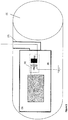
- FIG. 1 A very schematic illustration of an electrostatic coalescing device according to an embodiment of the invention is shown in Figure 1 .
- the electrostatic coalescing device is located inside a vessel or pipe 1.
- the vessel/pipe is provided with an inlet for receiving an emulsion to be treated by the coalescing device.
- the flow direction of the flow to be treated is in Figure 1 from left to right.
- Inside the vessel/pipe there is a metal (e.g. steel, aluminum, copper etc.) electrode plate 2 connected to a transformer 4.
- the metal electrode plate 2 and the transformer are fully enclosed by insulation 3.
- the transformer is energized from an external alternating low voltage source 5.
- the low voltage source is arranged on the outside of the pipe or vessel 1 in Figure 1 .
- the transformer has a first end of a high voltage winding 4a connected electrically to the metal plate 2.
- the second end of the high voltage winding 4a of the transformer is connected to a ground potential 6 of said vessel or pipe 1.
- the connection to ground 6 from the transformer is carried out of the insulation 3 in a fluid tight manner to ensure that no leakage shall occur into the enclosed metal plate and transformer.
- the low voltage winding 4b of the transformer is connected to an external power supply. This connection is also carried out of the insulation 3 in a fluid tight manner protected by a steel tubing 7.
- the protective steel tubing 7 is mechanically connected to the insulation 3 and to the pipe or vessel 1 wall, to provide a fluid tight guide for the connection from the low voltage side of the transformer to the external power source 5.
- the fluid tight mechanical connection to the insulation can be achieved either by sealings (e.g. o-rings) or by casting a connector into the insulation which is then welded to the protective tubing.
- sealings e.g. o-rings
- casting a connector into the insulation which is then welded to the protective tubing.
- On the vessel or pipe a standard penetrator design in a nozzle can be used or the protective tubing can be welded directly to the vessel or pipe wall.
- the plate and the transformer are molded in an insulating material forming an integrated module. Only a low voltage connection to the transformer from the outside is needed. Since a high voltage connector system is not used in the embodiment in Figure 1 , it is possible to vary the distance between the plates providing a highly flexible solution. The distance between the plates may be individually controlled, making it possible to minimize the risk of fouling and clogging of the device. This is important in installation on fields with crude oils containing large amounts of naphthenic acids, hard scale or soft scale.
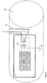
- Figure 2 provides a further embodiment of an electrostatic treater.
- the flow to be treated by the coalescing device is from left to right.
- the embodiment in Figure 2 provides a solution for energizing the plates through a plus/minus connection from the plates to an external power supply.
- both the ends/terminals of the low voltage winding of the transformer are connected to the external power supply 5.
- the connection to the external power supply is also provided inside the protective steel tubing 7, as in the embodiment in Figure 1 .
- the second end of the high voltage winding 4a of the transformer is connected to a ground potential 6 of said vessel or pipe 1.
- FIG 3 shows very schematically an alternative embodiment of an electrostatic treater.
- the flow to be treated by the coalescing device is from left to right.
- the embodiment in Figure 3 provides an alternative solution for energizing the plates through a plus/minus connection from the plates to an external power supply.
- a second end of a low voltage winding 4b of the transformer is within the insulation connected to a first terminal/end of the high voltage winding 4a.
- the second terminal/end of the low voltage winding 4b and the second terminal/end of the high voltage winding 4a are further connected to a ground potential 6 of said vessel or pipe.
- the first terminal/end of the low voltage winding 4b is carried out of the insulation through the protecting steel tubing 7 and electrically connected to the external power supply 5.
- the external power supply 5 is connected to a ground potential 6.
- the embodiment in Figure 3 only uses two wirings through the isolation material surrounding the metal plate and transformer. This provides termination of less wirings, reducing the installation time. In an offshore environment this may in particular be important. One connection may take 5 minutes, and an installation of a coalescing device may require connection of 300-400 plates. Also, a retrofit of the separator will take considerably less time, considerably reducing the production loss for the oil companies during such retrofit.
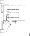
- FIG 4 shows very schematically an alternative embodiment of an electrostatic coalescer.
- the electrostatic coalescer is illustrated in a top view.
- the flow of emulsion to be treated is from the bottom to the top in Figure 4 .
- the electrostatic coalescer is in Figure 4 provided with a pair of insulated electrodes arranged at a distance from each other side-by-side so as to form a flow passage between them. Between any adjacent pair of such insulated plates there is a grounded conductive plate 2a.
- the conductive plate is grounded to the ground potential 6 of said vessel or pipe.
- the high voltage electric field is established by at least one plate according to Figures 1 or 2 , separated by a conductive electrode connected to ground. In this configuration a high voltage field is set up between the insulated plate and the conductive grounded plate.
- Figure 4 provides a solution for providing an electrical field between the plates in the coalescing device, using an active insulated electrode and a passive grounded electrode.
- the passive electrode may be insulated or may not be insulated.
- An electrical field is created, generated by the transformer, between the active and the passive electrode.
- the solution in Figure 4 does neither require synchronization of the active electrodes, since the passive electrode provides a grounded separation potential between the active electrodes.
- the solution in Figure 4 uses a higher peak voltage than a solution using a field between two active plus/minus electrodes (symmetrical system).
- the passive electrode is grounded.
- the extremal values on the voltage on the active electrode should be twice as high as compared to ground.
- the insulation on the active electrode will be exposed to twice the field when the plates are submerged into water (very conductive). Due to possible degradation/discharge of the insulation, it is desired to have a field as low as possible in the insulation.
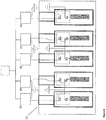
- FIG. 5 shows very schematically an alternative embodiment of an electrode configuration of an electrostatic coalescing device in the form of a number of insulated metal electrode plates 2, each plate having a dedicated integrated transformer 4.
- the flow of emulsion to be treated is from the bottom to the top.
- Each plate with transformer is also provided with an external dedicated power supply 5.
- the external power supply is a voltage source.
- the electrical connective wiring between the low voltage side of the transformer 4b and the dedicated power supply 5 is electrically twisted for every other plate. Both ends/terminals of the low voltage winding of the transformer are connected to the external power supply 5 as in the embodiment shown in Figure 2 .
- the connection to the external power supply is provided inside a protective steel tubing 7 and the wiring is twisted inside said tubing.
- All the external power supplies/voltage sources 5 are connected to a common timer 8 for synchronization.
- the timer 8 provides all insulating plates with an alternating voltage having the same frequency and with a common time reference, wherein adjacent plates are energized with the opposite polarity.
- the metal electrode plate 2 and the transformer are fully enclosed by insulation 3.
- the first end of a high voltage winding 4a of the transformer is connected electrically to the metal plate 2.
- the electrodes are connected in pairs, as the second end of the high voltage winding 4a of the transformer is connected to a high voltage winding 4a of an adjacent plate 2, and further connected to a ground potential 6 of the pipe or vessel.
- the embodiment in Figure 5 provides a +/- system, where all the electrodes are active.
- the electrodes used are according to the embodiment shown in Figure 2 .
- all the electrodes are supplied with a voltage having the same frequency, and where adjacent electrodes are provided with a potential of the opposite polarity.
- the opposite polarity is provided to the insulated plates themselves.
- all the dedicated power supplies start synchronously and have the same frequencies.
- the power supplies provide a voltage symmetrically about ground, since one end of the high voltage transformer is grounded. Every other plate should be out of phase by 180°, requiring that the wirings of every other power supply are twisted, as illustrated in Figure 5 .
- FIG 6 shows schematically a further alternative embodiment of an electrode configuration of an electrostatic coalescing device having a number of insulated metal electrode plates 2 (as shown in Figure 3 ), each plate having a dedicated integrated transformer 4.
- the flow of emulsion to be treated is from the bottom to the top.
- Each plate with transformer is also provided with an external dedicated power supply 5.
- the external power supply is an alternating voltage source.
- a second end of a low voltage winding 4b of the transformer is within the insulation connected to a first terminal/end of the high voltage winding 4a.
- the second terminal/end of the low voltage winding 4b and the second terminal/end of the high voltage winding 4a are further connected to a ground potential 6 of said vessel or pipe.
- the electrodes are connected in pairs, as the second terminal/end of the low voltage winding 4b and the second end of the high voltage winding 4a of the transformer is further connected to a corresponding high voltage winding 4a and low voltage winding 4b of an adjacent plate 2, and further connected to a ground potential 6 of the pipe or vessel.
- the first terminal/end of the low voltage winding 4b is carried out of the insulation through the protecting steel tubing 7 and electrically connected to the external power supply 5.
- the pairs of electrodes as defined above also have an opposite channel of their corresponding external power supplies 5 connected to each other, and further connected to the ground potential 6 of said pipe or vessel.
- the ground potential of said transformer terminals and the power supplies are the same. As in the embodiment in Figure 5 all the external power supplies are connected to the same timer 8 for synchronization.
- the embodiment in Figure 6 provides a +/- system, where all the electrodes are active. However, the electrodes used are according to Figure 3 . Also, in the embodiment in Figure 6 , to avoid beat frequencies, all the dedicated power supplies start synchronously and have the same frequencies. However, one pole of each power supply is grounded. The other pole is connected to the low voltage terminal 4b of the cast-in transformer. In order to achieve every other plate having a +/- potential, adjacent power supplies are connected to ground/earth through the opposite poles.
- inventions shown in Figures 4 , 5 and 6 provide rows of two or more sets/modules with parallel planar electrodes arranged in parallel with the flow direction of the emulsion providing a flow passage between them.
- the present invention can tolerate being fully submerged in water or standing in gas phase. As an earthed connector is not arranged directly in contact with the isolation, less electrical stresses are provided to the isolation.
- the invention is applicable to any type of oil-treatment line, it is particularly advantageous in offshore and onshore applications involving a coalescing device arranged for promoting or effectuating separation of water from oil or water droplet enlargement.
Landscapes
- Physics & Mathematics (AREA)
- Thermal Sciences (AREA)
- Chemical & Material Sciences (AREA)
- Chemical Kinetics & Catalysis (AREA)
- Production Of Liquid Hydrocarbon Mixture For Refining Petroleum (AREA)
- Electrostatic Separation (AREA)
Description
- The present invention relates to an electrostatic coalescing device.
- The invention is particularly applicable to electrostatic coalescing devices for promoting the coalescence of water in an emulsion comprising oil and water. However, the invention is applicable to any type of coalescing application where it possible to promote the coalescence of an emulsion component in an emulsion comprising a mixture of at least two different fluid components by means of an electric field applied to the emulsion.
- In the oil and gas industry where oil is extracted from one or more wells in an oil field, oil will be extracted together with water. The water has to be removed from the oil and this is mainly done by means of settling tanks in which the oil is permitted to settle under the action of gravity. However, stable oil-water emulsions may develop during the production of the oil. For example, the use of gas-liquid cyclones might contribute to a stable emulsion that will be difficult to separate only by means of settling. After having passed through, for example, a series of gravitational settling tanks, a certain amount of water normally remains in the oil in the form of droplets. In order to promote the separation of this remaining water content, which is difficult to separate from the oil only by means of further gravitational settling, different types of coalescing devices have been proposed taking advantage of the fact that water and oil have different permittivity.
- It is well known to use electrostatic coalescing devices in order to achieve water droplet enlargement or coalescence of water in water-in-oil emulsions, whereupon the water can be separated more easily from the oil, e.g. by means of gravitational separation or the like. An electrostatic coalescing device can be employed to speed up the separation of any emulsion where the continuous phase is an electrical insulator, such as oil, and the dispersed phase has a different permittivity than said continuous phase. The dispersed phase may for instance be an electrical conductor, such as water. In an electrostatic coalescing device, an emulsion is subjected to an alternating current field or to a continuous or pulsed direct current field.
-
WO 03/049834 A1 -
WO 2003/039706 discloses an electrostatic coalescing device comprising a number of tubular electrostatic coalescer elements. The tubular elements are extending in the flow direction and are arranged in a matrix substantially covering the entire cross sectional area of said vessel. An electrical field is applied to the fluids flowing through said coalescer elements. The electrodes may be insulated and energized trough a capacitive coupling from a central module. A complete transformer may be moulded into a central module. The high voltage secondary winding of the transformer may be insulated from the fluid, whereas the primary terminal winding is accessible from the outside. -
WO 2007/135503 andWO 2007/135506 describes an electrostatic coalescing device comprising pairs of sheet-shaped electrodes arranged at a distance from each other side-by-side so as to form a flow passage between them. Each of the electrodes comprising a sheet-shaped conductive member of electrically conductive material, the mutual distance between the conductive members of the two electrodes of a pair varies along the electrodes as seen in a direction perpendicular to the intended flow direction of fluid passing through the flow passage between the electrodes. A power supply supplies mutually different electric potentials to the conductive members of the electrodes of said pair so as to form an electric field between the electrodes. An electrode pair is connected to an external transformer. High voltage connections are complicated, highly sensitive to fouling, bulky, and not flexible. - The object of the present invention is to provide an electrostatic coalescing device of new and advantageous design.
- According to the invention, this object is achieved by an electrostatic coalescing device having the features defined in
claim 1. - The inventive coalescing device comprises: a vessel or a pipe through which a fluid to be treated may flow, at least one metal electrode plate and transformer arranged inside said pipe/vessel, wherein said electrode plate and transformer are fully enclosed by insulation to form a module, and wherein said transformer comprises a low voltage connection so that it can be electrically connected to an external alternating low voltage source/power supply located outside the vessel/pipe, said transformer having a first end of a high voltage winding connected electrically to the metal plate within the insulation, wherein the module is configured to be fully submerged in the flow to be treated.
- A second end of the high voltage winding may be carried out of the insulation and electrically connected to a ground potential of the vessel/pipe. The external power supply/voltage source may be electrically connected to a low voltage winding of the transformer. The electrical connection from the external power supply/voltage source to the low voltage winding of the transformer may be carried through the vessel or pipe in a steel tubing, wherein said steel tubing is mechanically connected to the insulation and is carried into/through the insulation. In an embodiment both ends of the low voltage winding may be carried through the insulation and out of said vessel/pipe in the protecting steel tubing and connected to the external power supply. In a further embodiment a second end of the low voltage winding of the transformer may, within the insulation, be connected to the second end of the high voltage winding connected to the ground potential, and a first end of the low voltage winding is carried out of the insulation in the protecting steel tubing and electrically connected to a first terminal of the external power supply, wherein a second terminal of the external power supply is connected to the ground potential.
- The electrostatic coalescing device may further comprise a number of adjacent insulated metal electrode plates, each of said insulated plates having a dedicated integrated transformer, wherein a grounded conductive plate is arranged between any adjacent pair of insulated plates. Alternatively, the electrostatic coalescing device may further comprise a number of adjacent insulated metal electrode plates, each of said insulated plates having a dedicated integrated transformer and a dedicated external power supply, wherein the ends of the low voltage winding of every other plate are electrically twisted providing adjacent plates to be energized with an opposite polarity. The electrostatic coalescing device may alternatively comprise a number of adjacent insulated metal electrode plates, each of said insulated plates having a dedicated integrated transformer and a dedicated external power supply, wherein the first end of the low voltage winding of every other plate is electrically twisted providing adjacent plates to be energized with an opposite polarity. The electrostatic coalescing device may as a further alternative embodiment comprise a number of insulated plates, each plate having a dedicated integrated transformer, wherein every other external power supply has the opposite terminal connected to a ground potential. The external power supplies/voltage sources may be connected to a common timer for synchronization, providing said insulated plates with an alternating voltage with a same frequency and a common time reference.
- The present invention relates to an element which can comprise a coalescing device located inside a pipe, a vessel, a tank, etc. The invention provides a fully electrically insulated high voltage coalescing sheet. The purpose of the high voltage coalescing sheet is to establish a high voltage electric field inside the volume of the pipe, vessel, or tank. The number of coalescing sheets is defined by the wanted field magnitude in the fluid in said vessel, pipe, or tank and the diameter of its cross-section. The use of sheets, as compared with pipes/channels as in
WO 2003/039706 , also enables constructions of long elements. Pipes/channels are prone to plugging and deposition of sand and other material in the fluid to be coalesced, and cannot be made very long. The use of sheet also enables construction of an oil polishing tool, since a high field may be created over a larger area, providing longer retention times in the electric field. The present invention also provides a configuration with no obstructions in the vertical direction, and sediments will therefore fall to the bottom of the tank and will not plug the equipment. Since the transformer is provided on a plate inside the insulation, the distance between the plates and the voltage may easily be varied. In this way, blocking of the coalescing device may be avoided at the same time as a high field between the plates is maintained. - In contrast to the solution described in
WO 2007/135506 , where at least two plates were connected to the same power supply means, the invention according to the present invention has only one plate connected to the high-voltage power supply means. The advantage of the present configuration is that no high-voltage connectors are needed. High-voltage connectors in fluids consisting of crude oil and water is a well known challenge that is both expensive and sets strong limits on the flexibility of electrode arrangements. Another large advantage of the present invention compared toWO 2007/135506 , is the flexibility of on-site adjustments of the electrode arrangement. InWO 2007/135506 , much of the assembly has to be performed in controlled environments on-shore, while the present invention, due to the fact that each plate is totally insulated together with its high-voltage power supply means, can be assembled on-site. - As with other fully insulated electrodes, the present invention can tolerate being fully submerged in water or standing in gas phase. There will also be less electrical stresses on the insulation, since an earthed connector is not provided directly on the insulation.
- Further advantages as well as advantageous features of the inventive coalescing device will appear from the following description and the dependent claims.
- With reference to the appended drawings, a specific description of preferred embodiments of the invention cited as examples follows below. In the drawings:
-
Figure 1 is a schematic side view of an electrostatic coalescer/treater according to a first embodiment of the invention. Flow is from left to right. -
Figure 2 is a schematic side view of an electrostatic coalescer according to a second embodiment of the invention. Flow is from left to right. -
Figure 3 is a schematic side view of an electrostatic coalescer according to a third embodiment of the invention. Flow is from right to left. -
Figure 4 is a schematic side view of an electrostatic coalescer according to an embodiment of the invention. Flow is from bottom to top. The external low-voltage source is moved to the side in order to make the sketch more understandable. -
Figure 5 is a schematic side view of an electrostatic coalescer according to an embodiment of the invention.Top view. Flow is from bottom to top. The external low-voltage sources are moved to the top in order to make the sketch more understandable. -
Figure 6 is a schematic side view of an electrostatic coalescer according to an embodiment of the invention. Top view. Flow is from bottom to top. The external low-voltage sources are moved to the top in order to make the sketch more understandable. - The present invention will be described with reference to the drawings. The same reference numerals are used for the same of similar features in all the drawings and throughout the description.
- A very schematic illustration of an electrostatic coalescing device according to an embodiment of the invention is shown in
Figure 1 . The electrostatic coalescing device is located inside a vessel orpipe 1. The vessel/pipe is provided with an inlet for receiving an emulsion to be treated by the coalescing device. The flow direction of the flow to be treated is inFigure 1 from left to right. Inside the vessel/pipe there is a metal (e.g. steel, aluminum, copper etc.)electrode plate 2 connected to atransformer 4. Themetal electrode plate 2 and the transformer are fully enclosed byinsulation 3. The transformer is energized from an external alternatinglow voltage source 5. The low voltage source is arranged on the outside of the pipe orvessel 1 inFigure 1 . The transformer has a first end of a high voltage winding 4a connected electrically to themetal plate 2. The second end of the high voltage winding 4a of the transformer is connected to aground potential 6 of said vessel orpipe 1. The connection toground 6 from the transformer is carried out of theinsulation 3 in a fluid tight manner to ensure that no leakage shall occur into the enclosed metal plate and transformer. The low voltage winding 4b of the transformer is connected to an external power supply. This connection is also carried out of theinsulation 3 in a fluid tight manner protected by asteel tubing 7. Theprotective steel tubing 7 is mechanically connected to theinsulation 3 and to the pipe orvessel 1 wall, to provide a fluid tight guide for the connection from the low voltage side of the transformer to theexternal power source 5. The fluid tight mechanical connection to the insulation can be achieved either by sealings (e.g. o-rings) or by casting a connector into the insulation which is then welded to the protective tubing. On the vessel or pipe a standard penetrator design in a nozzle can be used or the protective tubing can be welded directly to the vessel or pipe wall. - In the embodiment in
Figure 1 the plate and the transformer are molded in an insulating material forming an integrated module. Only a low voltage connection to the transformer from the outside is needed. Since a high voltage connector system is not used in the embodiment inFigure 1 , it is possible to vary the distance between the plates providing a highly flexible solution. The distance between the plates may be individually controlled, making it possible to minimize the risk of fouling and clogging of the device. This is important in installation on fields with crude oils containing large amounts of naphthenic acids, hard scale or soft scale. -
Figure 2 provides a further embodiment of an electrostatic treater. The flow to be treated by the coalescing device is from left to right. The embodiment inFigure 2 provides a solution for energizing the plates through a plus/minus connection from the plates to an external power supply. In this embodiment both the ends/terminals of the low voltage winding of the transformer are connected to theexternal power supply 5. The connection to the external power supply is also provided inside theprotective steel tubing 7, as in the embodiment inFigure 1 . As in the embodiment inFigure 1 , the second end of the high voltage winding 4a of the transformer is connected to aground potential 6 of said vessel orpipe 1. -
Figure 3 shows very schematically an alternative embodiment of an electrostatic treater. The flow to be treated by the coalescing device is from left to right. The embodiment inFigure 3 provides an alternative solution for energizing the plates through a plus/minus connection from the plates to an external power supply. InFigure 3 , a second end of a low voltage winding 4b of the transformer is within the insulation connected to a first terminal/end of the high voltage winding 4a. The second terminal/end of the low voltage winding 4b and the second terminal/end of the high voltage winding 4a are further connected to aground potential 6 of said vessel or pipe. The first terminal/end of the low voltage winding 4b is carried out of the insulation through the protectingsteel tubing 7 and electrically connected to theexternal power supply 5. Theexternal power supply 5 is connected to aground potential 6. Compared to the embodiment inFigure 2 , the embodiment inFigure 3 only uses two wirings through the isolation material surrounding the metal plate and transformer. This provides termination of less wirings, reducing the installation time. In an offshore environment this may in particular be important. One connection may take 5 minutes, and an installation of a coalescing device may require connection of 300-400 plates. Also, a retrofit of the separator will take considerably less time, considerably reducing the production loss for the oil companies during such retrofit. -
Figure 4 shows very schematically an alternative embodiment of an electrostatic coalescer. The electrostatic coalescer is illustrated in a top view. The flow of emulsion to be treated is from the bottom to the top inFigure 4 . The electrostatic coalescer is inFigure 4 provided with a pair of insulated electrodes arranged at a distance from each other side-by-side so as to form a flow passage between them. Between any adjacent pair of such insulated plates there is a grounded conductive plate 2a. The conductive plate is grounded to theground potential 6 of said vessel or pipe. Here the high voltage electric field is established by at least one plate according toFigures 1 or2 , separated by a conductive electrode connected to ground. In this configuration a high voltage field is set up between the insulated plate and the conductive grounded plate. Since all high-voltage plates are separated by a grounded plate on the same ground potential to which the second end of the high voltage winding is connected, phase differences in the electric field from different plates will not interfere with each other. Such interference may lead to cancelling of the electric field in the space between the high-voltage plates, which should be avoided. -
Figure 4 provides a solution for providing an electrical field between the plates in the coalescing device, using an active insulated electrode and a passive grounded electrode. The passive electrode may be insulated or may not be insulated. An electrical field is created, generated by the transformer, between the active and the passive electrode. The solution inFigure 4 does neither require synchronization of the active electrodes, since the passive electrode provides a grounded separation potential between the active electrodes. However, the solution inFigure 4 uses a higher peak voltage than a solution using a field between two active plus/minus electrodes (symmetrical system). InFigure 4 the passive electrode is grounded. To achieve the same field as in a symmetrical system, the extremal values on the voltage on the active electrode should be twice as high as compared to ground. In an active/passive system, the insulation on the active electrode will be exposed to twice the field when the plates are submerged into water (very conductive). Due to possible degradation/discharge of the insulation, it is desired to have a field as low as possible in the insulation. -
Figure 5 shows very schematically an alternative embodiment of an electrode configuration of an electrostatic coalescing device in the form of a number of insulatedmetal electrode plates 2, each plate having a dedicatedintegrated transformer 4. The flow of emulsion to be treated is from the bottom to the top. Each plate with transformer is also provided with an externaldedicated power supply 5. The external power supply is a voltage source. The electrical connective wiring between the low voltage side of thetransformer 4b and thededicated power supply 5 is electrically twisted for every other plate. Both ends/terminals of the low voltage winding of the transformer are connected to theexternal power supply 5 as in the embodiment shown inFigure 2 . The connection to the external power supply is provided inside aprotective steel tubing 7 and the wiring is twisted inside said tubing. All the external power supplies/voltage sources 5 are connected to a common timer 8 for synchronization. The timer 8 provides all insulating plates with an alternating voltage having the same frequency and with a common time reference, wherein adjacent plates are energized with the opposite polarity. - As in the previous embodiment described in
Figure 2 , themetal electrode plate 2 and the transformer are fully enclosed byinsulation 3. The first end of a high voltage winding 4a of the transformer is connected electrically to themetal plate 2. The electrodes are connected in pairs, as the second end of the high voltage winding 4a of the transformer is connected to a high voltage winding 4a of anadjacent plate 2, and further connected to aground potential 6 of the pipe or vessel. - The embodiment in
Figure 5 provides a +/- system, where all the electrodes are active. The electrodes used are according to the embodiment shown inFigure 2 . In such a system all the electrodes are supplied with a voltage having the same frequency, and where adjacent electrodes are provided with a potential of the opposite polarity. InFigure 5 the opposite polarity is provided to the insulated plates themselves. To avoid beat frequencies, all the dedicated power supplies start synchronously and have the same frequencies. The power supplies provide a voltage symmetrically about ground, since one end of the high voltage transformer is grounded. Every other plate should be out of phase by 180°, requiring that the wirings of every other power supply are twisted, as illustrated inFigure 5 . Although not shown inFigure 5 , it is also possible to use the electrodes according to the embodiment shown inFigure 1 orFigure 3 . In the embodiments inFigure 1 andFigure 3 , only a first end of the low voltage winding 4b of the transformer is taken out of the insulation, through theprotective steel tubing 7 and to theexternal power supply 5. When using the electrodes from the embodiments inFigures 1 and3 , the first end of the low voltage winding 4b is twisted, meaning that the first ends of thelow voltage windings 4b of adjacent electrodes are connected to terminals of the dedicatedexternal power supplies 5 having opposite polarity. -
Figure 6 shows schematically a further alternative embodiment of an electrode configuration of an electrostatic coalescing device having a number of insulated metal electrode plates 2 (as shown inFigure 3 ), each plate having a dedicatedintegrated transformer 4. The flow of emulsion to be treated is from the bottom to the top. Each plate with transformer is also provided with an externaldedicated power supply 5. The external power supply is an alternating voltage source. InFigure 6 a second end of a low voltage winding 4b of the transformer is within the insulation connected to a first terminal/end of the high voltage winding 4a. The second terminal/end of the low voltage winding 4b and the second terminal/end of the high voltage winding 4a are further connected to aground potential 6 of said vessel or pipe. The electrodes are connected in pairs, as the second terminal/end of the low voltage winding 4b and the second end of the high voltage winding 4a of the transformer is further connected to a corresponding high voltage winding 4a and low voltage winding 4b of anadjacent plate 2, and further connected to aground potential 6 of the pipe or vessel.
The first terminal/end of the low voltage winding 4b is carried out of the insulation through the protectingsteel tubing 7 and electrically connected to theexternal power supply 5. The pairs of electrodes as defined above also have an opposite channel of their correspondingexternal power supplies 5 connected to each other, and further connected to theground potential 6 of said pipe or vessel. The ground potential of said transformer terminals and the power supplies are the same. As in the embodiment inFigure 5 all the external power supplies are connected to the same timer 8 for synchronization. - As in
Figure 5 , the embodiment inFigure 6 provides a +/- system, where all the electrodes are active. However, the electrodes used are according toFigure 3 . Also, in the embodiment inFigure 6 , to avoid beat frequencies, all the dedicated power supplies start synchronously and have the same frequencies. However, one pole of each power supply is grounded. The other pole is connected to thelow voltage terminal 4b of the cast-in transformer. In order to achieve every other plate having a +/- potential, adjacent power supplies are connected to ground/earth through the opposite poles. - The embodiments shown in
Figures 4 ,5 and6 provide rows of two or more sets/modules with parallel planar electrodes arranged in parallel with the flow direction of the emulsion providing a flow passage between them. - As with other fully insulated electrodes, the present invention can tolerate being fully submerged in water or standing in gas phase. As an earthed connector is not arranged directly in contact with the isolation, less electrical stresses are provided to the isolation.
- Although the invention is applicable to any type of oil-treatment line, it is particularly advantageous in offshore and onshore applications involving a coalescing device arranged for promoting or effectuating separation of water from oil or water droplet enlargement.
- The invention is of course not in any way restricted to the embodiments described above. On the contrary, many possibilities to modifications thereof will be apparent to a person with ordinary skill in the art without departing from the scope of the invention as defined in the appended claims.
Claims (11)
- An electrostatic coalescing device comprising:- a vessel (1) or a pipe (1) through which a fluid to be treated may flow,- at least one metal electrode plate (2) and transformer (4) arranged inside said pipe/vessel (1), wherein the metal electrode plate (2) and the transformer (4) are fully enclosed by insulation (3) to form a module, and wherein said transformer (4) comprises a low voltage connection so that it can be electrically connected to an external alternating low voltage source/power supply (5) located outside the vessel/pipe (1), said transformer having a first end of a high voltage winding (4a) connected electrically to the metal plate (2) within the insulation (3),wherein the module is configured to be fully submerged in the flow to be treated.
- An electrostatic coalescing device according to claim 1, wherein a second end of the high voltage winding (4a) is carried out of the insulation and electrically connected to a ground potential (6) of the vessel/pipe (1).
- An electrostatic coalescing device according to claim 1 or 2, further comprising an external power supply/voltage source (5) which is electrically connected to a low voltage winding (4b) of the transformer (4).
- An electrostatic coalescing device according to claim 3, wherein the electrical connection from the external power supply/voltage source (5) to the low voltage winding (4b) of the transformer (4) is carried through the vessel (1) or pipe (1) in a steel tubing (7), wherein said steel tubing (7) is mechanically connected to the insulation (3) and is carried into/through the insulation (3).
- An electrostatic coalescing device according to claim 4, wherein both ends of the low voltage winding (4b) are carried through the insulation (3) and out of said vessel/pipe (1) in the steel tubing (7) and connected to the external power supply (5).
- An electrostatic coalescing device according to claim 4, wherein a second end of the low voltage winding (4b) of the transformer (4) is, within the insulation (3), connected to the second end of the high voltage winding (4a) connected to the ground potential (6), and that a first end of the low voltage winding (4b) is carried out of the insulation (3) in the steel tubing (7) and electrically connected to a first terminal of the external power supply (5), wherein a second terminal of the external power supply (5) is connected to the ground potential (6).
- An electrostatic coalescing device according to one of claims 1-6 , comprising a number of adjacent insulated metal electrode plates (2), each of said insulated plates (2) having a dedicated integrated transformer (5), wherein a grounded conductive plate (2a) is arranged between any adjacent pair of insulated plates (2).
- An electrostatic coalescing device according to one of claims 1-5, comprising a number of adjacent insulated metal electrode plates (2), each of said insulated plates (2) having a dedicated integrated transformer (4) and a dedicated external power supply (5), wherein the ends of the low voltage winding (4b) of every other plate (2) are electrically twisted providing adjacent plates (2) to be energized with an opposite polarity.
- An electrostatic coalescing device according to claim 6, comprising a number of adjacent insulated metal electrode plates (2), each of said insulated plates (2) having a dedicated integrated transformer (4) and a dedicated external power supply (5), wherein the first end of the low voltage winding (4b) of every other plate (2) is electrically twisted providing adjacent plates (2) to be energized with an opposite polarity.
- An electrostatic coalescing device according to one of claims 3-4 or 6, comprising a number of insulated plates (2), each plate having a dedicated integrated transformer (4), wherein every other external power supply (5) has the opposite terminal connected to a ground potential.
- An electrostatic coalescing device according to one of claims 8-10, wherein the external power supplies/voltage sources (5) are connected to a common timer (8) for synchronization, providing said insulated plates (2) with an alternating voltage with a same frequency and a common time reference.
Applications Claiming Priority (1)
| Application Number | Priority Date | Filing Date | Title |
|---|---|---|---|
| NO20100613A NO332147B1 (en) | 2010-04-28 | 2010-04-28 | Electrostatic coalescing device |
Publications (2)
| Publication Number | Publication Date |
|---|---|
| EP2383040A1 EP2383040A1 (en) | 2011-11-02 |
| EP2383040B1 true EP2383040B1 (en) | 2020-01-15 |
Family
ID=44170086
Family Applications (1)
| Application Number | Title | Priority Date | Filing Date |
|---|---|---|---|
| EP11155616.3A Active EP2383040B1 (en) | 2010-04-28 | 2011-02-23 | Electrostatic coalescing device |
Country Status (3)
| Country | Link |
|---|---|
| US (1) | US9039884B2 (en) |
| EP (1) | EP2383040B1 (en) |
| NO (1) | NO332147B1 (en) |
Families Citing this family (10)
| Publication number | Priority date | Publication date | Assignee | Title |
|---|---|---|---|---|
| WO2010054074A1 (en) * | 2008-11-05 | 2010-05-14 | Fmc Technologies, Inc. | Electrostatic coalescer with resonance tracking circuit |
| US10023811B2 (en) | 2016-09-08 | 2018-07-17 | Saudi Arabian Oil Company | Integrated gas oil separation plant for crude oil and natural gas processing |
| US10260010B2 (en) | 2017-01-05 | 2019-04-16 | Saudi Arabian Oil Company | Simultaneous crude oil dehydration, desalting, sweetening, and stabilization |
| CN107033948B (en) * | 2017-06-08 | 2018-12-25 | 江苏金门能源装备有限公司 | Using the Desalting and Dewatering from Crude Oil equipment and processing method of not same electric field combined application |
| CN108048128B (en) * | 2018-01-12 | 2023-10-31 | 北京石油化工学院 | External electrostatic coalescer of transformer |
| CN110328052B (en) * | 2019-05-30 | 2024-03-26 | 福建师范大学 | Electrostatic precipitator for server |
| US11398781B2 (en) * | 2019-11-05 | 2022-07-26 | Cameron International Corporation | Power supply unit, system and method for coalescence of multi-phase liquid mixtures |
| US11857895B2 (en) | 2021-11-03 | 2024-01-02 | Saudi Arabian Oil Company | Bi-phase (Scott-T) transformer double volted AC electrostatic coalescer |
| EP4197613A1 (en) * | 2021-12-17 | 2023-06-21 | Sulzer Management AG | A method for protecting the coalescer elements of an electrostatic coalescer device against electrically induced erosion and/or partial discharges |
| EP4385624A1 (en) * | 2022-12-16 | 2024-06-19 | Sulzer Management AG | A coalescer element with a two-layer electrical insulation |
Family Cites Families (8)
| Publication number | Priority date | Publication date | Assignee | Title |
|---|---|---|---|---|
| US4804453A (en) * | 1982-06-07 | 1989-02-14 | National Tank Company | Resolution of emulsions with multiple electric fields |
| US4702815A (en) * | 1986-05-05 | 1987-10-27 | National Tank Company | Distributed charge composition electrodes and desalting system |
| NO316109B1 (en) | 2001-11-07 | 2003-12-15 | Aibel As | A coalescer device |
| PL351182A1 (en) | 2001-12-13 | 2003-06-16 | Abb Sp Zoo | Electrostatic separator |
| US7758738B2 (en) * | 2002-08-07 | 2010-07-20 | National Tank Company | Separating multiple components of a stream |
| NO330039B1 (en) | 2006-05-16 | 2011-02-07 | Hamworthy Plc | Electrostatic coalescence |
| NO331954B1 (en) * | 2006-05-16 | 2012-05-14 | Hamworthy Plc | An electrostatic coalescing device |
| NO328576B1 (en) * | 2006-05-26 | 2010-03-22 | Hamworthy Plc | Electrical device |
-
2010
- 2010-04-28 NO NO20100613A patent/NO332147B1/en unknown
-
2011
- 2011-02-23 EP EP11155616.3A patent/EP2383040B1/en active Active
- 2011-03-24 US US13/070,536 patent/US9039884B2/en active Active
Non-Patent Citations (1)
| Title |
|---|
| None * |
Also Published As
| Publication number | Publication date |
|---|---|
| EP2383040A1 (en) | 2011-11-02 |
| US9039884B2 (en) | 2015-05-26 |
| NO332147B1 (en) | 2012-07-09 |
| NO20100613A1 (en) | 2011-10-31 |
| US20110266152A1 (en) | 2011-11-03 |
Similar Documents
| Publication | Publication Date | Title |
|---|---|---|
| EP2383040B1 (en) | Electrostatic coalescing device | |
| AU2002343160B2 (en) | Electrostatic coalescer device and use of the device | |
| EP1461131B1 (en) | An electrostatic separator | |
| AU2002343160A1 (en) | Electrostatic coalescer device and use of the device | |
| CN101173182B (en) | Novel crude oil emulsion electrostatic dehydrator | |
| US8282804B2 (en) | Electrostatic coalescing device | |
| WO2009101436A1 (en) | Rf heating of a dielectric fluid | |
| AU2002256837B2 (en) | A device for coalescing a fluid | |
| EP3262663B1 (en) | Subsea transformer with seawater high resistance ground | |
| AU2002256837A1 (en) | A device for coalescing a fluid | |
| US7964079B2 (en) | Electrostatic coalescing device | |
| CN103773428B (en) | A kind of high efficiency electrical desalting and dehydration equipment and application | |
| WO2008066392A2 (en) | Electrostatic coalescer | |
| GB1582040A (en) | Dual field electric treater |
Legal Events
| Date | Code | Title | Description |
|---|---|---|---|
| 17P | Request for examination filed |
Effective date: 20110408 |
|
| AK | Designated contracting states |
Kind code of ref document: A1 Designated state(s): AL AT BE BG CH CY CZ DE DK EE ES FI FR GB GR HR HU IE IS IT LI LT LU LV MC MK MT NL NO PL PT RO RS SE SI SK SM TR |
|
| AX | Request for extension of the european patent |
Extension state: BA ME |
|
| PUAI | Public reference made under article 153(3) epc to a published international application that has entered the european phase |
Free format text: ORIGINAL CODE: 0009012 |
|
| STAA | Information on the status of an ep patent application or granted ep patent |
Free format text: STATUS: EXAMINATION IS IN PROGRESS |
|
| 17Q | First examination report despatched |
Effective date: 20171117 |
|
| RAP1 | Party data changed (applicant data changed or rights of an application transferred) |
Owner name: SULZER MANAGEMENT AG |
|
| GRAP | Despatch of communication of intention to grant a patent |
Free format text: ORIGINAL CODE: EPIDOSNIGR1 |
|
| STAA | Information on the status of an ep patent application or granted ep patent |
Free format text: STATUS: GRANT OF PATENT IS INTENDED |
|
| INTG | Intention to grant announced |
Effective date: 20191018 |
|
| GRAS | Grant fee paid |
Free format text: ORIGINAL CODE: EPIDOSNIGR3 |
|
| GRAA | (expected) grant |
Free format text: ORIGINAL CODE: 0009210 |
|
| STAA | Information on the status of an ep patent application or granted ep patent |
Free format text: STATUS: THE PATENT HAS BEEN GRANTED |
|
| AK | Designated contracting states |
Kind code of ref document: B1 Designated state(s): AL AT BE BG CH CY CZ DE DK EE ES FI FR GB GR HR HU IE IS IT LI LT LU LV MC MK MT NL NO PL PT RO RS SE SI SK SM TR |
|
| REG | Reference to a national code |
Ref country code: CH Ref legal event code: EP Ref country code: GB Ref legal event code: FG4D |
|
| REG | Reference to a national code |
Ref country code: IE Ref legal event code: FG4D |
|
| REG | Reference to a national code |
Ref country code: AT Ref legal event code: REF Ref document number: 1224687 Country of ref document: AT Kind code of ref document: T Effective date: 20200215 |
|
| REG | Reference to a national code |
Ref country code: DE Ref legal event code: R096 Ref document number: 602011064605 Country of ref document: DE |
|
| REG | Reference to a national code |
Ref country code: NO Ref legal event code: T2 Effective date: 20200115 |
|
| REG | Reference to a national code |
Ref country code: NL Ref legal event code: FP |
|
| REG | Reference to a national code |
Ref country code: LT Ref legal event code: MG4D |
|
| PG25 | Lapsed in a contracting state [announced via postgrant information from national office to epo] |
Ref country code: FI Free format text: LAPSE BECAUSE OF FAILURE TO SUBMIT A TRANSLATION OF THE DESCRIPTION OR TO PAY THE FEE WITHIN THE PRESCRIBED TIME-LIMIT Effective date: 20200115 Ref country code: RS Free format text: LAPSE BECAUSE OF FAILURE TO SUBMIT A TRANSLATION OF THE DESCRIPTION OR TO PAY THE FEE WITHIN THE PRESCRIBED TIME-LIMIT Effective date: 20200115 Ref country code: PT Free format text: LAPSE BECAUSE OF FAILURE TO SUBMIT A TRANSLATION OF THE DESCRIPTION OR TO PAY THE FEE WITHIN THE PRESCRIBED TIME-LIMIT Effective date: 20200607 |
|
| PG25 | Lapsed in a contracting state [announced via postgrant information from national office to epo] |
Ref country code: HR Free format text: LAPSE BECAUSE OF FAILURE TO SUBMIT A TRANSLATION OF THE DESCRIPTION OR TO PAY THE FEE WITHIN THE PRESCRIBED TIME-LIMIT Effective date: 20200115 Ref country code: BG Free format text: LAPSE BECAUSE OF FAILURE TO SUBMIT A TRANSLATION OF THE DESCRIPTION OR TO PAY THE FEE WITHIN THE PRESCRIBED TIME-LIMIT Effective date: 20200415 Ref country code: LV Free format text: LAPSE BECAUSE OF FAILURE TO SUBMIT A TRANSLATION OF THE DESCRIPTION OR TO PAY THE FEE WITHIN THE PRESCRIBED TIME-LIMIT Effective date: 20200115 Ref country code: SE Free format text: LAPSE BECAUSE OF FAILURE TO SUBMIT A TRANSLATION OF THE DESCRIPTION OR TO PAY THE FEE WITHIN THE PRESCRIBED TIME-LIMIT Effective date: 20200115 Ref country code: IS Free format text: LAPSE BECAUSE OF FAILURE TO SUBMIT A TRANSLATION OF THE DESCRIPTION OR TO PAY THE FEE WITHIN THE PRESCRIBED TIME-LIMIT Effective date: 20200515 Ref country code: GR Free format text: LAPSE BECAUSE OF FAILURE TO SUBMIT A TRANSLATION OF THE DESCRIPTION OR TO PAY THE FEE WITHIN THE PRESCRIBED TIME-LIMIT Effective date: 20200416 |
|
| REG | Reference to a national code |
Ref country code: CH Ref legal event code: PL |
|
| REG | Reference to a national code |
Ref country code: DE Ref legal event code: R097 Ref document number: 602011064605 Country of ref document: DE |
|
| REG | Reference to a national code |
Ref country code: BE Ref legal event code: MM Effective date: 20200229 |
|
| PG25 | Lapsed in a contracting state [announced via postgrant information from national office to epo] |
Ref country code: CZ Free format text: LAPSE BECAUSE OF FAILURE TO SUBMIT A TRANSLATION OF THE DESCRIPTION OR TO PAY THE FEE WITHIN THE PRESCRIBED TIME-LIMIT Effective date: 20200115 Ref country code: RO Free format text: LAPSE BECAUSE OF FAILURE TO SUBMIT A TRANSLATION OF THE DESCRIPTION OR TO PAY THE FEE WITHIN THE PRESCRIBED TIME-LIMIT Effective date: 20200115 Ref country code: SK Free format text: LAPSE BECAUSE OF FAILURE TO SUBMIT A TRANSLATION OF THE DESCRIPTION OR TO PAY THE FEE WITHIN THE PRESCRIBED TIME-LIMIT Effective date: 20200115 Ref country code: MC Free format text: LAPSE BECAUSE OF FAILURE TO SUBMIT A TRANSLATION OF THE DESCRIPTION OR TO PAY THE FEE WITHIN THE PRESCRIBED TIME-LIMIT Effective date: 20200115 Ref country code: SM Free format text: LAPSE BECAUSE OF FAILURE TO SUBMIT A TRANSLATION OF THE DESCRIPTION OR TO PAY THE FEE WITHIN THE PRESCRIBED TIME-LIMIT Effective date: 20200115 Ref country code: DK Free format text: LAPSE BECAUSE OF FAILURE TO SUBMIT A TRANSLATION OF THE DESCRIPTION OR TO PAY THE FEE WITHIN THE PRESCRIBED TIME-LIMIT Effective date: 20200115 Ref country code: EE Free format text: LAPSE BECAUSE OF FAILURE TO SUBMIT A TRANSLATION OF THE DESCRIPTION OR TO PAY THE FEE WITHIN THE PRESCRIBED TIME-LIMIT Effective date: 20200115 Ref country code: ES Free format text: LAPSE BECAUSE OF FAILURE TO SUBMIT A TRANSLATION OF THE DESCRIPTION OR TO PAY THE FEE WITHIN THE PRESCRIBED TIME-LIMIT Effective date: 20200115 Ref country code: LU Free format text: LAPSE BECAUSE OF NON-PAYMENT OF DUE FEES Effective date: 20200223 Ref country code: LT Free format text: LAPSE BECAUSE OF FAILURE TO SUBMIT A TRANSLATION OF THE DESCRIPTION OR TO PAY THE FEE WITHIN THE PRESCRIBED TIME-LIMIT Effective date: 20200115 |
|
| REG | Reference to a national code |
Ref country code: AT Ref legal event code: MK05 Ref document number: 1224687 Country of ref document: AT Kind code of ref document: T Effective date: 20200115 |
|
| PLBE | No opposition filed within time limit |
Free format text: ORIGINAL CODE: 0009261 |
|
| STAA | Information on the status of an ep patent application or granted ep patent |
Free format text: STATUS: NO OPPOSITION FILED WITHIN TIME LIMIT |
|
| PG25 | Lapsed in a contracting state [announced via postgrant information from national office to epo] |
Ref country code: LI Free format text: LAPSE BECAUSE OF NON-PAYMENT OF DUE FEES Effective date: 20200229 Ref country code: CH Free format text: LAPSE BECAUSE OF NON-PAYMENT OF DUE FEES Effective date: 20200229 |
|
| 26N | No opposition filed |
Effective date: 20201016 |
|
| PG25 | Lapsed in a contracting state [announced via postgrant information from national office to epo] |
Ref country code: AT Free format text: LAPSE BECAUSE OF FAILURE TO SUBMIT A TRANSLATION OF THE DESCRIPTION OR TO PAY THE FEE WITHIN THE PRESCRIBED TIME-LIMIT Effective date: 20200115 Ref country code: IE Free format text: LAPSE BECAUSE OF NON-PAYMENT OF DUE FEES Effective date: 20200223 |
|
| PG25 | Lapsed in a contracting state [announced via postgrant information from national office to epo] |
Ref country code: PL Free format text: LAPSE BECAUSE OF FAILURE TO SUBMIT A TRANSLATION OF THE DESCRIPTION OR TO PAY THE FEE WITHIN THE PRESCRIBED TIME-LIMIT Effective date: 20200115 Ref country code: SI Free format text: LAPSE BECAUSE OF FAILURE TO SUBMIT A TRANSLATION OF THE DESCRIPTION OR TO PAY THE FEE WITHIN THE PRESCRIBED TIME-LIMIT Effective date: 20200115 Ref country code: BE Free format text: LAPSE BECAUSE OF NON-PAYMENT OF DUE FEES Effective date: 20200229 |
|
| PG25 | Lapsed in a contracting state [announced via postgrant information from national office to epo] |
Ref country code: TR Free format text: LAPSE BECAUSE OF FAILURE TO SUBMIT A TRANSLATION OF THE DESCRIPTION OR TO PAY THE FEE WITHIN THE PRESCRIBED TIME-LIMIT Effective date: 20200115 Ref country code: MT Free format text: LAPSE BECAUSE OF FAILURE TO SUBMIT A TRANSLATION OF THE DESCRIPTION OR TO PAY THE FEE WITHIN THE PRESCRIBED TIME-LIMIT Effective date: 20200115 Ref country code: CY Free format text: LAPSE BECAUSE OF FAILURE TO SUBMIT A TRANSLATION OF THE DESCRIPTION OR TO PAY THE FEE WITHIN THE PRESCRIBED TIME-LIMIT Effective date: 20200115 |
|
| PG25 | Lapsed in a contracting state [announced via postgrant information from national office to epo] |
Ref country code: MK Free format text: LAPSE BECAUSE OF FAILURE TO SUBMIT A TRANSLATION OF THE DESCRIPTION OR TO PAY THE FEE WITHIN THE PRESCRIBED TIME-LIMIT Effective date: 20200115 Ref country code: AL Free format text: LAPSE BECAUSE OF FAILURE TO SUBMIT A TRANSLATION OF THE DESCRIPTION OR TO PAY THE FEE WITHIN THE PRESCRIBED TIME-LIMIT Effective date: 20200115 |
|
| P01 | Opt-out of the competence of the unified patent court (upc) registered |
Effective date: 20230608 |
|
| PGFP | Annual fee paid to national office [announced via postgrant information from national office to epo] |
Ref country code: NL Payment date: 20240219 Year of fee payment: 14 |
|
| PGFP | Annual fee paid to national office [announced via postgrant information from national office to epo] |
Ref country code: DE Payment date: 20240219 Year of fee payment: 14 Ref country code: GB Payment date: 20240219 Year of fee payment: 14 |
|
| PGFP | Annual fee paid to national office [announced via postgrant information from national office to epo] |
Ref country code: NO Payment date: 20240222 Year of fee payment: 14 Ref country code: IT Payment date: 20240228 Year of fee payment: 14 Ref country code: FR Payment date: 20240221 Year of fee payment: 14 |