EP2382904A1 - Adjustable food processor with guide ramp - Google Patents
Adjustable food processor with guide ramp Download PDFInfo
- Publication number
- EP2382904A1 EP2382904A1 EP11163933A EP11163933A EP2382904A1 EP 2382904 A1 EP2382904 A1 EP 2382904A1 EP 11163933 A EP11163933 A EP 11163933A EP 11163933 A EP11163933 A EP 11163933A EP 2382904 A1 EP2382904 A1 EP 2382904A1
- Authority
- EP
- European Patent Office
- Prior art keywords
- rotating disk
- cutting blade
- food
- control knob
- assembly
- Prior art date
- Legal status (The legal status is an assumption and is not a legal conclusion. Google has not performed a legal analysis and makes no representation as to the accuracy of the status listed.)
- Granted
Links
- 235000013305 food Nutrition 0.000 title claims abstract description 90
- 230000001419 dependent effect Effects 0.000 claims 3
- 230000008859 change Effects 0.000 description 3
- 238000000034 method Methods 0.000 description 3
- 238000012986 modification Methods 0.000 description 3
- 230000004048 modification Effects 0.000 description 3
- 239000000853 adhesive Substances 0.000 description 2
- 230000001070 adhesive effect Effects 0.000 description 2
- 230000003247 decreasing effect Effects 0.000 description 2
- 239000000463 material Substances 0.000 description 2
- 240000002129 Malva sylvestris Species 0.000 description 1
- 235000006770 Malva sylvestris Nutrition 0.000 description 1
- 235000013351 cheese Nutrition 0.000 description 1
- 235000013399 edible fruits Nutrition 0.000 description 1
- 235000012055 fruits and vegetables Nutrition 0.000 description 1
- 235000013372 meat Nutrition 0.000 description 1
- 230000007246 mechanism Effects 0.000 description 1
- 239000007769 metal material Substances 0.000 description 1
- 238000002156 mixing Methods 0.000 description 1
- 230000002093 peripheral effect Effects 0.000 description 1
- 230000008569 process Effects 0.000 description 1
- 235000013311 vegetables Nutrition 0.000 description 1
Images



Classifications
-
- A—HUMAN NECESSITIES
- A47—FURNITURE; DOMESTIC ARTICLES OR APPLIANCES; COFFEE MILLS; SPICE MILLS; SUCTION CLEANERS IN GENERAL
- A47J—KITCHEN EQUIPMENT; COFFEE MILLS; SPICE MILLS; APPARATUS FOR MAKING BEVERAGES
- A47J43/00—Implements for preparing or holding food, not provided for in other groups of this subclass
- A47J43/04—Machines for domestic use not covered elsewhere, e.g. for grinding, mixing, stirring, kneading, emulsifying, whipping or beating foodstuffs, e.g. power-driven
- A47J43/07—Parts or details, e.g. mixing tools, whipping tools
- A47J43/0716—Parts or details, e.g. mixing tools, whipping tools for machines with tools driven from the lower side
- A47J43/0722—Mixing, whipping or cutting tools
-
- B—PERFORMING OPERATIONS; TRANSPORTING
- B26—HAND CUTTING TOOLS; CUTTING; SEVERING
- B26D—CUTTING; DETAILS COMMON TO MACHINES FOR PERFORATING, PUNCHING, CUTTING-OUT, STAMPING-OUT OR SEVERING
- B26D3/00—Cutting work characterised by the nature of the cut made; Apparatus therefor
- B26D3/18—Cutting work characterised by the nature of the cut made; Apparatus therefor to obtain cubes or the like
- B26D3/22—Cutting work characterised by the nature of the cut made; Apparatus therefor to obtain cubes or the like using rotating knives
- B26D3/225—Cutting work characterised by the nature of the cut made; Apparatus therefor to obtain cubes or the like using rotating knives with adjustable knives
-
- B—PERFORMING OPERATIONS; TRANSPORTING
- B26—HAND CUTTING TOOLS; CUTTING; SEVERING
- B26D—CUTTING; DETAILS COMMON TO MACHINES FOR PERFORATING, PUNCHING, CUTTING-OUT, STAMPING-OUT OR SEVERING
- B26D7/00—Details of apparatus for cutting, cutting-out, stamping-out, punching, perforating, or severing by means other than cutting
- B26D7/26—Means for mounting or adjusting the cutting member; Means for adjusting the stroke of the cutting member
- B26D7/2628—Means for adjusting the position of the cutting member
-
- B—PERFORMING OPERATIONS; TRANSPORTING
- B26—HAND CUTTING TOOLS; CUTTING; SEVERING
- B26D—CUTTING; DETAILS COMMON TO MACHINES FOR PERFORATING, PUNCHING, CUTTING-OUT, STAMPING-OUT OR SEVERING
- B26D1/00—Cutting through work characterised by the nature or movement of the cutting member or particular materials not otherwise provided for; Apparatus or machines therefor; Cutting members therefor
- B26D1/01—Cutting through work characterised by the nature or movement of the cutting member or particular materials not otherwise provided for; Apparatus or machines therefor; Cutting members therefor involving a cutting member which does not travel with the work
- B26D1/12—Cutting through work characterised by the nature or movement of the cutting member or particular materials not otherwise provided for; Apparatus or machines therefor; Cutting members therefor involving a cutting member which does not travel with the work having a cutting member moving about an axis
- B26D1/25—Cutting through work characterised by the nature or movement of the cutting member or particular materials not otherwise provided for; Apparatus or machines therefor; Cutting members therefor involving a cutting member which does not travel with the work having a cutting member moving about an axis with a non-circular cutting member
- B26D1/26—Cutting through work characterised by the nature or movement of the cutting member or particular materials not otherwise provided for; Apparatus or machines therefor; Cutting members therefor involving a cutting member which does not travel with the work having a cutting member moving about an axis with a non-circular cutting member moving about an axis substantially perpendicular to the line of cut
- B26D1/28—Cutting through work characterised by the nature or movement of the cutting member or particular materials not otherwise provided for; Apparatus or machines therefor; Cutting members therefor involving a cutting member which does not travel with the work having a cutting member moving about an axis with a non-circular cutting member moving about an axis substantially perpendicular to the line of cut and rotating continuously in one direction during cutting
- B26D1/29—Cutting through work characterised by the nature or movement of the cutting member or particular materials not otherwise provided for; Apparatus or machines therefor; Cutting members therefor involving a cutting member which does not travel with the work having a cutting member moving about an axis with a non-circular cutting member moving about an axis substantially perpendicular to the line of cut and rotating continuously in one direction during cutting with cutting member mounted in the plane of a rotating disc, e.g. for slicing beans
-
- B—PERFORMING OPERATIONS; TRANSPORTING
- B26—HAND CUTTING TOOLS; CUTTING; SEVERING
- B26D—CUTTING; DETAILS COMMON TO MACHINES FOR PERFORATING, PUNCHING, CUTTING-OUT, STAMPING-OUT OR SEVERING
- B26D3/00—Cutting work characterised by the nature of the cut made; Apparatus therefor
- B26D3/24—Cutting work characterised by the nature of the cut made; Apparatus therefor to obtain segments other than slices, e.g. cutting pies
- B26D3/26—Cutting work characterised by the nature of the cut made; Apparatus therefor to obtain segments other than slices, e.g. cutting pies specially adapted for cutting fruit or vegetables, e.g. for onions
Definitions
- the present disclosure relates generally to a domestic food processor, and more particularly to a food processor having a control for adjusting the cutting thickness of the food processor.
- a food processor is a motorized domestic appliance for manipulating (e.g., chopping, slicing, dicing, shredding, grating, or blending) food items.
- Such an appliance includes a bowl with a removable lid. Food items are inserted into the bowl through a feed tube formed in the lid where they are cut by motor-driven cutting tool.
- Food processors typically come equipped with a number of interchangeable cutting tools for slicing, shredding, or other food processing operations.
- One common cutting tool is a rotating disk-type cutter.
- Such a cutting tool includes a rotating disk having a cutting blade fixed thereto. The cutting blade is secured to the rotating disk at a location adjacent to an aperture formed in the disk so that pieces of food cut by the blade fall through the aperture and collect in the bottom of the bowl.
- a food processing device includes a base having a motor positioned therein, a removable bowl coupled to the base, and a removable lid coupled to the bowl so as to define a processing chamber.
- the lid has a feed tube that opens into the bowl.
- the food processing device also includes a blade assembly positioned in the processing chamber, which is driven by the motor and includes a cutting blade to cut food items advanced through the feed tube, and a rotating disk upwardly and downwardly moveable relative to the cutting blade to adjust the distance between an upper surface of the rotating disk and the cutting blade.
- the food processing device also includes an adjustment assembly operable to move the rotating disk relative to the cutting blade.
- the adjustment assembly includes a control knob coupled to the blade assembly and is positioned above the upper surface of the rotating disk, and a threaded sleeve coupled to the rotating disk and is positioned in the control knob.
- the rotating disk may divide the processing chamber into an upper compartment and a lower compartment
- the blade assembly may include a mounting arm having a ramp defined therein to guide food items from the upper compartment to the lower compartment.
- the ramp may have an inclined surface extending outwardly in a radial direction from a first end to a second end.
- the inclined surface may have a first angle of inclination at the first end and a second angle of inclination at the second end.
- the first angle of inclination may be greater than or equal to the second angle of inclination.
- the first angle of inclination may be approximately 25 degrees.
- the second angle of inclination may be approximately 15 degrees.
- the rotating disk may have a counterweight secured thereto, and the threaded sleeve may be positioned between the mounting arm and the counterweight.
- rotation of the control knob in a first direction may cause upward movement of the rotating disk, and rotation of the control knob in a second direction may cause downward movement of the rotating disk.
- the blade assembly may include a central shaft coupled to the control knob, and the central shaft may be received in the threaded sleeve. Rotation of the control knob may cause the threaded sleeve to move upwardly and downwardly along the central shaft.
- a food slicer assembly for a food processor.
- the food slicer assembly includes a cutting blade, a mounting arm, which has a ramp defined therein, that is positioned below the cutting blade, and a rotating disk moveable to a plurality of positions relative to the cutting blade to adjust the distance between its upper surface and the cutting blade.
- An adjustment assembly is operable to move the rotating disk relative to the cutting blade.
- the adjustment assembly includes an internally-threaded control knob positioned above the upper surface of the rotating disk, and an externally-threaded sleeve coupled to the rotating disk that is positioned in the control knob.
- the food slicer assembly may further include a central shaft that is coupled at an upper end to the control knob and is positioned in the sleeve.
- the mounting arm may extend outwardly from a first end secured to the central shaft to a second end positioned adjacent to an outer rim of the rotating disk.
- the ramp may have an inclined surface extending in a radial direction from the first end of the mounting arm to the second end of the mounting arm. The inclined surface may have a first angle of inclination at the first end that is greater than or equal to a second angle of inclination at the second end.
- the rotating disk may include a counterweight, and the sleeve may be positioned between the counterweight and the mounting arm.
- a food processor includes a base having a motor positioned therein, a removable bowl coupled to the base, and a removable lid coupled to the bowl so as to define a processing chamber.
- the lid has a feed tube that opens into the bowl.
- a cutting blade is positioned in the bowl and driven by the motor to cut food items advanced through the feed tube.
- a rotating disk is upwardly and downwardly moveable relative to the cutting blade to adjust the distance therebetween.
- the rotating disk divides the processing chamber into an upper compartment and a lower compartment.
- a ramp is positioned below the cutting blade to guide food items from the upper compartment into the lower compartment.
- the food processor further includes an adjustment assembly operable to move the rotating disk relative to the cutting blade.
- the adjustment assembly includes a user-operated control device positioned above the rotating disk.
- the adjustment assembly may include an externally-threaded sleeve coupled to the rotating disk, and the user-operated control device may include an internally-threaded control knob having a grip.
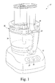
- FIG. 1 is a perspective view of a food processor
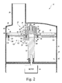
- FIG. 2 is a partial cross-sectional view of the food processor of FIG. 1 ;
- FIG. 3 is a view similar to FIG. 2 , showing the rotating disk of the food slicer assembly in another position relative to the cutting blade;
- FIG. 4 is a perspective view of a food slicer assembly of the food processor of FIG. 1 ;
- FIG. 5 is a partial cross sectional view of the food slicer assembly of FIG. 4 taken along the line 5-5;
- FIG. 6 is a partial cross sectional view of the food slicer assembly of FIG. 4 taken along the line 6-6 showing the angle of inclination of the ramp.
- a food processing device or food processor 10 is shown.
- a food processor is the KitchenAid® 12-Cup Ultra Wide MouthTM Food Processor, Base Model No. KFPW760OB, which is commercially available from Whirlpool Corporation of Benton Harbor, MI, U.S.A.
- the food processor 10 has a base 12 that houses a motor 14 (shown schematically in FIG. 2 ) and a control unit (not shown). Under the control of the control unit, the motor's output shaft 16 drives a cutting blade 18 (see FIG. 2 ) to cut food items such as cheeses, meats, fruits, and vegetables.
- the base 12 also includes one or more buttons, switches, dials, or other types of controls 20.
- a user operates the controls 20 to control the operation of the motor 14 and hence the food processor 10. For instance, one of the controls 20 may be operable to turn the motor 14 on and off, while another control 20 may change the motor's speed.
- control unit may comprise analog and/or digital circuitry to process electrical signals received from the motor 14 (or other components of the food processor 10) and provide electrical control signals to the motor or other components of the food processor 10.
- control unit may be embodied as a microcontroller that executes firmware routines to control the operation of the food processor 10.
- a removable bowl 22 is secured to the base 12.
- the bowl's handle facilitates placement of the bowl 22 on the base 12.
- the bowl 22 includes a removable lid 26 secured to its upper peripheral edge.
- the lid 26 has a feed tube 28 formed thereon through which food items such as fruits and vegetables are inserted into the bowl 22 to be processed by the food processor 10.
- Collectively, the lid 26 and the bowl 22 define a processing chamber 24 where food items are processed by the cutting blade 18.
- the bowl 22, lid 26, and feed tube 28 are generally made of a transparent or translucent plastic material, so that the contents of the food processor 10 can be viewed by a user without removing the lid 26 from the bowl 22.
- one or more locking mechanisms may be used to lock the bowl to the base 12 and the lid 26 to the bowl 22.
- the output shaft 16 of the motor 14 is coupled to a drive stem 30.
- the drive stem 30 is in turn coupled to a food slicer assembly 32.
- the food slicer assembly 32 includes a rotating disk 34, a thickness adjustment assembly 36, and a blade assembly 38, with the cutting blade 18 being one component thereof.
- the rotating disk 34 effectively divides the processing chamber 24 into an upper compartment 40 located between the disk 34 and the lid 26, and a lower compartment 42 located below the rotating disk 34.
- a vertical distance, D, between the cutting edge 44 of the cutting blade 18 and the upper surface 46 of the rotating disk 34 defines a cutting thickness.
- the thickness of the pieces of food items cut by the food processor 10 is determined by the distance D between the cutting edge 44 of the cutting blade 18 and the upper surface 46 of the rotating disk 34.
- the distance D between the cutting edge 44 of the cutting blade 18 and the upper surface 46 of the rotating disk 34 is increased, thicker pieces of food items are created, with thinner pieces of food items being created when the distance D between the cutting edge 44 of the cutting blade 18 and the upper surface 46 of the rotating disk 34 is decreased.
- the rotating disk 34 includes a planar body 52 and a rim 54 that extends upwardly from the outer perimeter of the planar body 52.
- the rotating disk 34 has a diameter that is slightly less than the inner diameter of the bowl 22 such that the rim 54 is positioned adjacent to, but spaced slightly apart from, the inner wall of the bowl to permit rotation of the disk 34 within the bowl 22.
- the rotating disk 34 is embodied as a monolithic structure (e.g., a single molded or cast part).
- the components of the rotating disk 34 e.g., body 52 and rim 54
- the thickness adjustment assembly 36 is operable by a user to vary the cutting thickness of the food processor 10 thereby creating thicker or thinner pieces of cut food items.
- the adjustment assembly 36 includes a hub 60 and a user-operated control device 62.
- the hub 60 includes a base 64 and a hollow sleeve 66 extending upwardly therefrom.
- a number of fasteners 68 i.e., screws
- the hub 60 and the rotating disk 34 may be integrally formed as a monolithic structure.
- the sleeve 66 extends through an opening 69 formed in the planar body 52.
- External threads 70 are defined on a portion of an outer surface 72 of the sleeve 66.
- the user-operated control device 62 is positioned above the upper surface 46 of the rotating disk 34. As shown in FIGS. 2-4 , the user-operated control device 62 includes a control knob 74.
- the control knob 74 has a body 76 that extends from a lower end 78 to an upper end 80.
- the body 76 includes a knurled grip 82 formed in the upper end 80 and an annular flange 84 extending outwardly from the lower end 78. It should be appreciated that other user-activated control devices, such as levers, dials, buttons, or the like, may be substituted for the control knob.
- the body 76 of the control knob 74 has an aperture 86 formed in the lower end 78 that receives the sleeve 66 of the hub 60.
- the inner surface 88 of the aperture 86 has internal threads 90 defined therein that correspond to the external threads 70 of the hub 60.
- the internal threads 90 of the control knob 74 threadingly engage the external threads 70 of the hub 60 to move the hub 60 (and hence the rotating disk 34) upwardly and downwardly relative to the cutting blade 18.
- clockwise rotation of the control knob 74 causes upward movement of the hub 60 (and hence the rotating disk 34)
- counter-clockwise rotation of the control knob 74 causes downward movement of the hub 60 (and hence the rotating disk 34).
- a central shaft 98 of the blade assembly 38 is received in the hollow sleeve 66 of the adjustment assembly 36 and is secured at an upper end 102 to the control knob 74.
- the central shaft 98 extends from the upper end 102 to a lower end 104, which is has an opening 106 that receives the drive stem 30.
- the slicer assembly 32 is coupled to the output shaft 16 such that the slicer assembly 32 may be driven by the motor 14.
- the blade assembly 38 also includes a mounting arm 110 extending from an inner end 112, which is secured to the lower end 104 of the central shaft 98, to an outer end 114, which is positioned adjacent to the rim 54 of the rotating disk 34.
- the central shaft 98 and mounting arm 110 are formed as a single monolithic component from a plastic or metallic material. It should be appreciated that in other embodiments the shaft 98 and arm 110 may be formed as separate components that are joined during final assembly by an adhesive or other suitable fastener.
- the cutting blade 18 is secured to an upper surface 116 of the mounting arm 110.
- a number of fasteners 120 i.e., screws
- the fasteners 120 may take the form of T-stakes, pins, posts, or other structures capable of securing the cutting blade 18 to the mounting arm 110.
- the mounting arm 110 may include an overmold that receives the cutting blade 18.
- the opening 69 formed in the planar body 52 extends radially outward and receives the mounting arm 110 and the cutting blade 18.
- the food slicer assembly 32 also includes a counterweight 126 coupled to the planar body 52 adjacent to the outer perimeter of the rotating disk 34.
- the hub 60 is positioned between the counterweight 126 and the cutting blade 18.
- the counterweight 126 is sized to offset the weight of the mounting arm 110 and the cutting blade 18. In that way, the counterweight 126 balances the slicer assembly 32 as it is rotated.
- the separate counterweight 126 may be omitted and additional material may be added to the rim 54 and the planar body 52 such that the counterweight is incorporated into the rotating disk 34.
- the user may change the cutting position of the rotating disk 34 using the control knob 74.
- the control knob 74 When the control knob 74 is rotated, the hub 60 translates upwardly and downwardly along the central shaft 98 to change the thickness of the food items being processed by the food processor 10.
- counter-clockwise rotation of the control knob 74 causes downward movement of the hub 60 (and hence rotating disk 34), which increases the distance D between the cutting edge 44 of the cutting blade 18 and the upper surface 46 of the rotating disk 34 and thereby produces thicker pieces of food items.
- the motor 14 causes the blade assembly 38 to rotate.
- the blade assembly 38 acts on the hub 60 secured to the rotating disk 34 such that the rotating disk 34 and the blade assembly 38 rotate together.
- Food items inserted through the feed tube 28 are urged into contact with the upper surface 46 of the rotating disk 34 while being acted upon (i.e., cut) by the cutting blade 18. Cut food items, along with other food items small enough to fit within the throat 124, pass from the upper compartment 40 through the throat 124.
- a ramp 130 defined in the mounting arm 110 guides food items from the upper compartment 40 to the lower compartment 42.
- the ramp 130 is positioned adjacent to and below the cutting blade 18 and includes an inclined surface 132 extending downwardly from the underside of cutting blade 18.
- the inclined surface 132 extends from the inner end 112 of the mounting arm 110 radially outward to the outer end 114 of the mounting arm 110.
- the inner end 112 defines an inner sidewall 134 for the ramp 130
- the outer end 114 of the mounting arm 110 defines an outer sidewall 136. In that way, the inclined surface 132 is encapsulated or captured between the sidewalls 134, 136, thereby reducing the potential for food items to travel outside of the processing path and thus reducing unwanted debris.
- the slope or angle of the inclined surface 132 relative to the cutting blade 18 changes as the inclined surface 132 extends radially outward.
- the inclined surface 132 has an angle of inclination ⁇ at the outer end 114.
- the inclined surface 132 has an angle of inclination ⁇ that is greater than the angle ⁇ .
- the angle ⁇ is approximately 15 degrees
- the angle ⁇ is approximately 25 degrees.
- angles ⁇ , ⁇ may be greater than or less than those of the illustrative embodiment. Additionally, in some embodiments, the angles ⁇ , ⁇ may be equal. In still other embodiments, the inclined surface 132 may be convex or concave in one or more directions.
- food processing device 10 is herein illustrated as a conventional domestic food processor, the features and aspects disclosed herein can also be implemented in other types of food processing devices such as automatic food slicers, dicers, ice shavers and the like.
- the rotating disk could be directly coupled to motor, and the blade could be moveable relative to the rotating disk.
Landscapes
- Engineering & Computer Science (AREA)
- Mechanical Engineering (AREA)
- Life Sciences & Earth Sciences (AREA)
- Forests & Forestry (AREA)
- Food Science & Technology (AREA)
- Food-Manufacturing Devices (AREA)
Abstract
Description
- The present disclosure relates generally to a domestic food processor, and more particularly to a food processor having a control for adjusting the cutting thickness of the food processor.
- A food processor is a motorized domestic appliance for manipulating (e.g., chopping, slicing, dicing, shredding, grating, or blending) food items. Such an appliance includes a bowl with a removable lid. Food items are inserted into the bowl through a feed tube formed in the lid where they are cut by motor-driven cutting tool.
- Food processors typically come equipped with a number of interchangeable cutting tools for slicing, shredding, or other food processing operations. One common cutting tool is a rotating disk-type cutter. Such a cutting tool includes a rotating disk having a cutting blade fixed thereto. The cutting blade is secured to the rotating disk at a location adjacent to an aperture formed in the disk so that pieces of food cut by the blade fall through the aperture and collect in the bottom of the bowl.
- According to one aspect of the disclosure, a food processing device is disclosed. The food processing device includes a base having a motor positioned therein, a removable bowl coupled to the base, and a removable lid coupled to the bowl so as to define a processing chamber. The lid has a feed tube that opens into the bowl. The food processing device also includes a blade assembly positioned in the processing chamber, which is driven by the motor and includes a cutting blade to cut food items advanced through the feed tube, and a rotating disk upwardly and downwardly moveable relative to the cutting blade to adjust the distance between an upper surface of the rotating disk and the cutting blade. The food processing device also includes an adjustment assembly operable to move the rotating disk relative to the cutting blade. The adjustment assembly includes a control knob coupled to the blade assembly and is positioned above the upper surface of the rotating disk, and a threaded sleeve coupled to the rotating disk and is positioned in the control knob.
- In some embodiments, the rotating disk may divide the processing chamber into an upper compartment and a lower compartment, and the blade assembly may include a mounting arm having a ramp defined therein to guide food items from the upper compartment to the lower compartment. In some embodiments, the ramp may have an inclined surface extending outwardly in a radial direction from a first end to a second end.
- The inclined surface may have a first angle of inclination at the first end and a second angle of inclination at the second end. In some embodiments, the first angle of inclination may be greater than or equal to the second angle of inclination. Additionally, in some embodiments, the first angle of inclination may be approximately 25 degrees. In some embodiments, the second angle of inclination may be approximately 15 degrees.
- In some embodiments, the rotating disk may have a counterweight secured thereto, and the threaded sleeve may be positioned between the mounting arm and the counterweight. In some embodiments, rotation of the control knob in a first direction may cause upward movement of the rotating disk, and rotation of the control knob in a second direction may cause downward movement of the rotating disk.
- In some embodiments, the blade assembly may include a central shaft coupled to the control knob, and the central shaft may be received in the threaded sleeve. Rotation of the control knob may cause the threaded sleeve to move upwardly and downwardly along the central shaft.
- According to another aspect, a food slicer assembly for a food processor is disclosed. The food slicer assembly includes a cutting blade, a mounting arm, which has a ramp defined therein, that is positioned below the cutting blade, and a rotating disk moveable to a plurality of positions relative to the cutting blade to adjust the distance between its upper surface and the cutting blade. An adjustment assembly is operable to move the rotating disk relative to the cutting blade. The adjustment assembly includes an internally-threaded control knob positioned above the upper surface of the rotating disk, and an externally-threaded sleeve coupled to the rotating disk that is positioned in the control knob.
- In some embodiments, the food slicer assembly may further include a central shaft that is coupled at an upper end to the control knob and is positioned in the sleeve. The mounting arm may extend outwardly from a first end secured to the central shaft to a second end positioned adjacent to an outer rim of the rotating disk. In some embodiments, the ramp may have an inclined surface extending in a radial direction from the first end of the mounting arm to the second end of the mounting arm. The inclined surface may have a first angle of inclination at the first end that is greater than or equal to a second angle of inclination at the second end. In some embodiments, the rotating disk may include a counterweight, and the sleeve may be positioned between the counterweight and the mounting arm.
- According to another aspect, a food processor includes a base having a motor positioned therein, a removable bowl coupled to the base, and a removable lid coupled to the bowl so as to define a processing chamber. The lid has a feed tube that opens into the bowl. A cutting blade is positioned in the bowl and driven by the motor to cut food items advanced through the feed tube. A rotating disk is upwardly and downwardly moveable relative to the cutting blade to adjust the distance therebetween. The rotating disk divides the processing chamber into an upper compartment and a lower compartment. A ramp is positioned below the cutting blade to guide food items from the upper compartment into the lower compartment. The food processor further includes an adjustment assembly operable to move the rotating disk relative to the cutting blade. The adjustment assembly includes a user-operated control device positioned above the rotating disk.
- In some embodiments, the adjustment assembly may include an externally-threaded sleeve coupled to the rotating disk, and the user-operated control device may include an internally-threaded control knob having a grip.
- The invention will be further described by way of example in the following detailed description which particularly refers to the accompanying figures, in which:
-
FIG. 1 is a perspective view of a food processor; -
FIG. 2 is a partial cross-sectional view of the food processor ofFIG. 1 ; -
FIG. 3 is a view similar toFIG. 2 , showing the rotating disk of the food slicer assembly in another position relative to the cutting blade; -
FIG. 4 is a perspective view of a food slicer assembly of the food processor ofFIG. 1 ; -
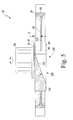
FIG. 5 is a partial cross sectional view of the food slicer assembly ofFIG. 4 taken along the line 5-5; and -
FIG. 6 is a partial cross sectional view of the food slicer assembly ofFIG. 4 taken along the line 6-6 showing the angle of inclination of the ramp. - While the concepts of the present disclosure are susceptible to various modifications and alternative forms, specific exemplary embodiments thereof have been shown by way of example in the drawings and will herein be described in detail. It should be understood, however, that there is no intent to limit the concepts of the present disclosure to the particular forms disclosed, but on the contrary, the intention is to cover all modifications, equivalents, and alternatives falling within the scope of the invention as defined by the appended claims.
- Referring to
FIG. 1 , a food processing device orfood processor 10 is shown. One example of a food processor is the KitchenAid® 12-Cup Ultra Wide Mouth™ Food Processor, Base Model No. KFPW760OB, which is commercially available from Whirlpool Corporation of Benton Harbor, MI, U.S.A. Thefood processor 10 has abase 12 that houses a motor 14 (shown schematically inFIG. 2 ) and a control unit (not shown). Under the control of the control unit, the motor'soutput shaft 16 drives a cutting blade 18 (seeFIG. 2 ) to cut food items such as cheeses, meats, fruits, and vegetables. Thebase 12 also includes one or more buttons, switches, dials, or other types ofcontrols 20. A user operates thecontrols 20 to control the operation of themotor 14 and hence thefood processor 10. For instance, one of thecontrols 20 may be operable to turn themotor 14 on and off, while anothercontrol 20 may change the motor's speed. - As will be understood by those skilled in the art, the control unit may comprise analog and/or digital circuitry to process electrical signals received from the motor 14 (or other components of the food processor 10) and provide electrical control signals to the motor or other components of the
food processor 10. For example, the control unit may be embodied as a microcontroller that executes firmware routines to control the operation of thefood processor 10. - A
removable bowl 22 is secured to thebase 12. The bowl's handle facilitates placement of thebowl 22 on thebase 12. Thebowl 22 includes aremovable lid 26 secured to its upper peripheral edge. Thelid 26 has afeed tube 28 formed thereon through which food items such as fruits and vegetables are inserted into thebowl 22 to be processed by thefood processor 10. Collectively, thelid 26 and thebowl 22 define aprocessing chamber 24 where food items are processed by thecutting blade 18. - The
bowl 22,lid 26, and feedtube 28 are generally made of a transparent or translucent plastic material, so that the contents of thefood processor 10 can be viewed by a user without removing thelid 26 from thebowl 22. Moreover, one or more locking mechanisms may be used to lock the bowl to thebase 12 and thelid 26 to thebowl 22. - As shown in
FIGS. 2 and3 , when theremovable bowl 22 is secured to thebase 12, theoutput shaft 16 of themotor 14 is coupled to adrive stem 30. Thedrive stem 30 is in turn coupled to afood slicer assembly 32. As shown inFIGS. 2-4 , thefood slicer assembly 32 includes arotating disk 34, athickness adjustment assembly 36, and ablade assembly 38, with thecutting blade 18 being one component thereof. Therotating disk 34 effectively divides theprocessing chamber 24 into anupper compartment 40 located between thedisk 34 and thelid 26, and alower compartment 42 located below therotating disk 34. A vertical distance, D, between the cuttingedge 44 of thecutting blade 18 and theupper surface 46 of therotating disk 34 defines a cutting thickness. In other words, the thickness of the pieces of food items cut by thefood processor 10 is determined by the distance D between the cuttingedge 44 of thecutting blade 18 and theupper surface 46 of therotating disk 34. When the distance D between the cuttingedge 44 of thecutting blade 18 and theupper surface 46 of therotating disk 34 is increased, thicker pieces of food items are created, with thinner pieces of food items being created when the distance D between the cuttingedge 44 of thecutting blade 18 and theupper surface 46 of therotating disk 34 is decreased. - The
rotating disk 34 includes aplanar body 52 and arim 54 that extends upwardly from the outer perimeter of theplanar body 52. Therotating disk 34 has a diameter that is slightly less than the inner diameter of thebowl 22 such that therim 54 is positioned adjacent to, but spaced slightly apart from, the inner wall of the bowl to permit rotation of thedisk 34 within thebowl 22. In the exemplary embodiment described herein, therotating disk 34 is embodied as a monolithic structure (e.g., a single molded or cast part). However, it should be appreciated that the components of the rotating disk 34 (e.g.,body 52 and rim 54) may be embodied as separate components secured to one another by an adhesive or other suitable fastener. - The
thickness adjustment assembly 36 is operable by a user to vary the cutting thickness of thefood processor 10 thereby creating thicker or thinner pieces of cut food items. Theadjustment assembly 36 includes ahub 60 and a user-operatedcontrol device 62. Thehub 60 includes abase 64 and ahollow sleeve 66 extending upwardly therefrom. A number of fasteners 68 (i.e., screws) extend through theplanar body 52 into thebase 64, thereby rigidly securing therotating disk 34 to thehub 60. It will be appreciated that in other embodiments thehub 60 and therotating disk 34 may be integrally formed as a monolithic structure. As shown inFIGS. 2 and3 , thesleeve 66 extends through anopening 69 formed in theplanar body 52.External threads 70 are defined on a portion of an outer surface 72 of thesleeve 66. - The user-operated
control device 62 is positioned above theupper surface 46 of therotating disk 34. As shown inFIGS. 2-4 , the user-operatedcontrol device 62 includes acontrol knob 74. Thecontrol knob 74 has abody 76 that extends from alower end 78 to anupper end 80. Thebody 76 includes aknurled grip 82 formed in theupper end 80 and anannular flange 84 extending outwardly from thelower end 78. It should be appreciated that other user-activated control devices, such as levers, dials, buttons, or the like, may be substituted for the control knob. - As shown in
FIGS. 2 and3 , thebody 76 of thecontrol knob 74 has anaperture 86 formed in thelower end 78 that receives thesleeve 66 of thehub 60. Theinner surface 88 of theaperture 86 hasinternal threads 90 defined therein that correspond to theexternal threads 70 of thehub 60. Theinternal threads 90 of thecontrol knob 74 threadingly engage theexternal threads 70 of thehub 60 to move the hub 60 (and hence the rotating disk 34) upwardly and downwardly relative to thecutting blade 18. For example, clockwise rotation of thecontrol knob 74 causes upward movement of the hub 60 (and hence the rotating disk 34), while counter-clockwise rotation of thecontrol knob 74 causes downward movement of the hub 60 (and hence the rotating disk 34). - As shown in
FIGS. 2 and3 , acentral shaft 98 of theblade assembly 38 is received in thehollow sleeve 66 of theadjustment assembly 36 and is secured at anupper end 102 to thecontrol knob 74. Thecentral shaft 98 extends from theupper end 102 to alower end 104, which is has anopening 106 that receives thedrive stem 30. In that way, theslicer assembly 32 is coupled to theoutput shaft 16 such that theslicer assembly 32 may be driven by themotor 14. Theblade assembly 38 also includes a mountingarm 110 extending from aninner end 112, which is secured to thelower end 104 of thecentral shaft 98, to anouter end 114, which is positioned adjacent to therim 54 of therotating disk 34. In the illustrative embodiment, thecentral shaft 98 and mountingarm 110 are formed as a single monolithic component from a plastic or metallic material. It should be appreciated that in other embodiments theshaft 98 andarm 110 may be formed as separate components that are joined during final assembly by an adhesive or other suitable fastener. - The
cutting blade 18 is secured to an upper surface 116 of the mountingarm 110. A number of fasteners 120 (i.e., screws) positioned at arear edge 122 of thecutting blade 18 extend into the mountingarm 110, thereby rigidly securing thecutting blade 18 to the mountingarm 110. It will be appreciated that in other embodiments thefasteners 120 may take the form of T-stakes, pins, posts, or other structures capable of securing thecutting blade 18 to the mountingarm 110. Additionally, the mountingarm 110 may include an overmold that receives thecutting blade 18. - As shown in
FIG. 4 , theopening 69 formed in theplanar body 52 extends radially outward and receives the mountingarm 110 and thecutting blade 18. When thefood slicer assembly 32 is assembled, a gap orthroat 124 is defined between the cuttingedge 44 and thebody 52, as best seen inFIGS. 4 and5 . Thefood slicer assembly 32 also includes acounterweight 126 coupled to theplanar body 52 adjacent to the outer perimeter of therotating disk 34. As shown inFIGS. 2 and3 , thehub 60 is positioned between thecounterweight 126 and thecutting blade 18. Thecounterweight 126 is sized to offset the weight of the mountingarm 110 and thecutting blade 18. In that way, thecounterweight 126 balances theslicer assembly 32 as it is rotated. In other embodiments, theseparate counterweight 126 may be omitted and additional material may be added to therim 54 and theplanar body 52 such that the counterweight is incorporated into therotating disk 34. - During operation, the user may change the cutting position of the
rotating disk 34 using thecontrol knob 74. When thecontrol knob 74 is rotated, thehub 60 translates upwardly and downwardly along thecentral shaft 98 to change the thickness of the food items being processed by thefood processor 10. In particular, counter-clockwise rotation of thecontrol knob 74 causes downward movement of the hub 60 (and hence rotating disk 34), which increases the distance D between the cuttingedge 44 of thecutting blade 18 and theupper surface 46 of therotating disk 34 and thereby produces thicker pieces of food items. Oppositely, when thecontrol knob 74 is rotated clockwise, thehub 60 is moved upwardly along thecentral shaft 98 and the distance D between the cuttingedge 44 of thecutting blade 18 and theupper surface 46 of therotating disk 34 is decreased, thereby producing thinner pieces of food items. - When the
food processor 10 is activated, themotor 14 causes theblade assembly 38 to rotate. Theblade assembly 38 acts on thehub 60 secured to therotating disk 34 such that therotating disk 34 and theblade assembly 38 rotate together. Food items inserted through thefeed tube 28 are urged into contact with theupper surface 46 of therotating disk 34 while being acted upon (i.e., cut) by thecutting blade 18. Cut food items, along with other food items small enough to fit within thethroat 124, pass from theupper compartment 40 through thethroat 124. - A
ramp 130 defined in the mountingarm 110 guides food items from theupper compartment 40 to thelower compartment 42. As shown inFIG. 5 , theramp 130 is positioned adjacent to and below thecutting blade 18 and includes aninclined surface 132 extending downwardly from the underside of cuttingblade 18. Theinclined surface 132 extends from theinner end 112 of the mountingarm 110 radially outward to theouter end 114 of the mountingarm 110. As shown inFIGS. 2 and3 , theinner end 112 defines aninner sidewall 134 for theramp 130, while theouter end 114 of the mountingarm 110 defines anouter sidewall 136. In that way, theinclined surface 132 is encapsulated or captured between thesidewalls - As shown in
FIGS. 5 and6 , the slope or angle of theinclined surface 132 relative to thecutting blade 18 changes as theinclined surface 132 extends radially outward. As shown inFIG. 5 , which is a cross-section of theslicer assembly 32 taken at theouter end 114 of the mountingarm 110, theinclined surface 132 has an angle of inclination α at theouter end 114. As shown inFIG. 6 , which is a cross-section of theslicer assembly 32 taken at theinner end 112 of the mountingarm 110, theinclined surface 132 has an angle of inclination β that is greater than the angle α. In the illustrative embodiment, the angle α is approximately 15 degrees, and the angle β is approximately 25 degrees. It will be appreciated that in other embodiments the angles α, β may be greater than or less than those of the illustrative embodiment. Additionally, in some embodiments, the angles α, β may be equal. In still other embodiments, theinclined surface 132 may be convex or concave in one or more directions. - While the disclosure has been illustrated and described in detail in the drawings and foregoing description, such an illustration and description is to be considered as exemplary and not restrictive in character, it being understood that only illustrative embodiments have been shown and described and that all changes and modifications that come within the spirit of the disclosure are desired to be protected.
- For example, while
food processing device 10 is herein illustrated as a conventional domestic food processor, the features and aspects disclosed herein can also be implemented in other types of food processing devices such as automatic food slicers, dicers, ice shavers and the like. Similarly, in other embodiments, the rotating disk could be directly coupled to motor, and the blade could be moveable relative to the rotating disk. - There are a plurality of advantages arising from the various features of the method, apparatus, and system described above. It will be noted that alternative embodiments of the method, apparatus, and system of the present disclosure may not include all of the features described yet still fall within the scope of the invention as defined by the appended claims.
Claims (12)
- A food processing device comprising: a base having a motor positioned therein, a removable bowl coupled to the base, a removable lid coupled to the bowl so as to define a processing chamber, the lid having a feed tube that opens into the bowl, a cutting blade driven by the motor to cut food items advanced through the feed tube, a rotating disk upwardly and downwardly moveable relative to the cutting blade to adjust the distance therebetween, and an adjustment assembly operable to move the rotating disk relative to the cutting blade, wherein the adjustment assembly includes a user-operable control device positioned above the rotating disk.
- The food processing device of claim 1, wherein:the cutting blade is included in a blade assembly positioned in the processing chamber; the rotating disk includes an upper surface, said adjustable distance being between the upper surface of the rotating disk and the cutting blade; and wherein the user-operable control device comprises (i) a control knob coupled to the blade assembly and positioned above the upper surface of the rotating disk and (ii) a threaded sleeve coupled to the rotating disk and positioned in the control knob.
- The food processing device of claim 2, wherein: the rotating disk divides the processing chamber into an upper compartment and a lower compartment, and the blade assembly includes a mounting arm having a ramp defined therein to guide food items from the upper compartment to the lower compartment.
- The food processing device of claim 2 or 3, wherein: the blade assembly includes a central shaft coupled to the control knob, the central shaft being received in the threaded sleeve, and rotation of the control knob causes the threaded sleeve to move upwardly and downwardly along the central shaft.
- A food slicer assembly for a food processor, comprising: a cutting blade, a mounting arm positioned below the cutting blade, the mounting arm having a ramp defined therein, a rotating disk including an upper surface, the rotating disk being moveable to a plurality of positions relative to the cutting blade to adjust the distance between the upper surface and the cutting blade, and an adjustment assembly operable to move the rotating disk relative to the cutting blade, wherein the adjustment assembly includes (i) an internally-threaded control knob positioned above the upper surface of the rotating disk, and (ii) an externally-threaded sleeve coupled to the rotating disk and positioned in the control knob.
- The food slicer assembly of claim 5, further comprising: a central shaft coupled at an upper end to the control knob and positioned in the sleeve, wherein the mounting arm extends outwardly from a first end secured to the central shaft to a second end positioned adjacent to an outer rim of the rotating disk.
- A food processor according to claim 1 wherein: the rotating disk divides the processing chamber into an upper compartment and a lower compartment, and a ramp is positioned below the cutting blade to guide food items from the upper compartment into the lower compartment.
- The food processor of claim 7, wherein the adjustment assembly includes an externally-threaded sleeve coupled to the rotating disk, the user-operated control device includes an internally-threaded control knob having a grip, and the sleeve is positioned in the control knob.
- The food processor of claim 2 or the food slicer assembly of claim 5, or any claim dependent from them, wherein: rotation of the control knob in a first direction causes upward movement of the rotating disk, and
rotation of the control knob in a second direction causes downward movement of the rotating disk. - The food processor of claim 3 or 7, or the slicer assembly of any of claims 5, or any claim dependent from them, wherein the ramp includes an inclined surface, the inclined surface extending outwardly in a radial direction from a first end to a second end and having a first angle of inclination at the first end that is greater than or equal to a second angle of inclination at the second end.
- The food processor or slicer assembly of claim 10, wherein the first angle of inclination is approximately 25 degrees and/or the second angle of inclination is approximately 15 degrees.
- The food processor of claim 2 or the slicer assembly of claim 5, or any claim dependent from them, wherein the rotating disk has a counterweight secured thereto, and the threaded sleeve is positioned between the mounting arm and the counterweight.
Applications Claiming Priority (1)
| Application Number | Priority Date | Filing Date | Title |
|---|---|---|---|
| US12/769,796 US8439285B2 (en) | 2010-04-29 | 2010-04-29 | Adjustable food processor with guide ramp |
Publications (2)
| Publication Number | Publication Date |
|---|---|
| EP2382904A1 true EP2382904A1 (en) | 2011-11-02 |
| EP2382904B1 EP2382904B1 (en) | 2013-11-06 |
Family
ID=44269251
Family Applications (1)
| Application Number | Title | Priority Date | Filing Date |
|---|---|---|---|
| EP11163933.2A Not-in-force EP2382904B1 (en) | 2010-04-29 | 2011-04-27 | Adjustable food processor with guide ramp |
Country Status (4)
| Country | Link |
|---|---|
| US (2) | US8439285B2 (en) |
| EP (1) | EP2382904B1 (en) |
| AU (1) | AU2011201948B2 (en) |
| CA (1) | CA2736231C (en) |
Cited By (3)
| Publication number | Priority date | Publication date | Assignee | Title |
|---|---|---|---|---|
| FR3034974A1 (en) * | 2015-04-17 | 2016-10-21 | Seb Sa | ROTARY CUTTING TOOL |
| CN107617499A (en) * | 2017-08-07 | 2018-01-23 | 昆明理工大学 | A kind of double-deck pulverizer mill and its Ginding process |
| US12053123B2 (en) | 2022-03-02 | 2024-08-06 | Sharkninja Operating Llc | Adjustable blade assembly for a food processor |
Families Citing this family (23)
| Publication number | Priority date | Publication date | Assignee | Title |
|---|---|---|---|---|
| US10449685B2 (en) | 2010-04-29 | 2019-10-22 | Whirlpool Corporation | Food processor with adjustable blade assembly |
| DK2561780T3 (en) * | 2011-08-25 | 2014-09-29 | Electrolux Professionel Sas | Cutting disc for cutting food and associated appliance. |
| US8944357B2 (en) | 2012-10-30 | 2015-02-03 | Whirlpool Corporation | Multifunctional food processing tool for use with a food processing device |
| USD694572S1 (en) | 2013-02-28 | 2013-12-03 | Whirlpool Corporation | Food processor |
| US9033269B2 (en) | 2013-03-01 | 2015-05-19 | Whirlpool Corporation | Linear path food processor |
| US10413109B2 (en) | 2013-03-13 | 2019-09-17 | Spectrum Brands, Inc. | Food preparation appliance for steam cooking and food processing |
| US9867504B2 (en) * | 2013-04-08 | 2018-01-16 | Conair Corporation | Locking mechanism for food processor blade assembly |
| CN203619410U (en) * | 2013-11-28 | 2014-06-04 | 广东德豪润达电气股份有限公司 | Food processor with shredding/slicing function |
| US20150245925A1 (en) * | 2014-02-28 | 2015-09-03 | Bacterin International, Inc. | Cutting assembly and method of use |
| EP3130264B1 (en) * | 2015-07-23 | 2020-02-05 | Sunbeam Products, Inc. | Food processor with slice selector disc |
| CN108430285A (en) * | 2015-10-20 | 2018-08-21 | 品谱公司 | Food processor helical cut attachment |
| USD796896S1 (en) * | 2015-12-03 | 2017-09-12 | Seb S.A. | Electric food processor with a chopper bowl |
| US10334986B2 (en) | 2016-07-13 | 2019-07-02 | Eternal East (HK) Ltd. | Method and device for making nut butter and nut milk |
| US10086523B2 (en) | 2016-10-17 | 2018-10-02 | Paul Roman RODRIGUEZ, JR. | Adjustable slicer |
| USD850221S1 (en) * | 2017-03-10 | 2019-06-04 | Eternal East (HK) Ltd. | Nut milk maker |
| USD878847S1 (en) | 2017-09-06 | 2020-03-24 | Eternal East (HK) Ltd. | Nut milk maker |
| US11166592B2 (en) | 2017-09-25 | 2021-11-09 | Whirlpool Corporation | Food processor |
| JP7060444B2 (en) * | 2018-05-23 | 2022-04-26 | 株式会社アイホー | Food slicer |
| CA3132666A1 (en) * | 2019-03-06 | 2020-09-10 | Innovative Brewing, Llc | Devices and methods for brewing beverages |
| US11618176B2 (en) * | 2019-04-11 | 2023-04-04 | Sunbeam Products, Inc. | Multifunction food slicer |
| TWD211462S (en) * | 2020-01-16 | 2021-05-11 | 比利時商寶貝利斯法寇有限公司 | Electric chopper |
| ES2916251B2 (en) | 2020-12-29 | 2022-12-27 | Sammic Sl | Refined Detachable Cutting Assembly |
| CN112847552A (en) * | 2021-01-05 | 2021-05-28 | 中山市欧博尔电器有限公司 | Dicing device |
Citations (4)
| Publication number | Priority date | Publication date | Assignee | Title |
|---|---|---|---|---|
| US4560111A (en) * | 1984-01-04 | 1985-12-24 | Alfredo Cavalli | Electric household appliance for cutting fruit, vegetables and similar food products into small sticks or chunks of variable thickness |
| FR2582497A1 (en) * | 1985-05-31 | 1986-12-05 | Coggiola Marcel | Cutting device for food processor |
| US20080156913A1 (en) * | 2006-12-19 | 2008-07-03 | Jill Kreutzer Orent | Food processor |
| US20090314168A1 (en) * | 2007-12-12 | 2009-12-24 | Krasznai Charles Z | Adjustable width slicing disc for a food processor |
Family Cites Families (17)
| Publication number | Priority date | Publication date | Assignee | Title |
|---|---|---|---|---|
| US2189199A (en) | 1938-09-03 | 1940-02-06 | Bush Ag | Spacing apparatus |
| US3199860A (en) | 1962-09-10 | 1965-08-10 | Moberg Frank | Sheet material cutting apparatus |
| US3623525A (en) | 1970-05-13 | 1971-11-30 | Raymond Kieves | Adjustable radially arranged food-slicing assembly |
| US4190208A (en) | 1978-10-27 | 1980-02-26 | General Electric Company | Processor and cutter disc |
| US4283979A (en) * | 1979-07-10 | 1981-08-18 | North American Philips Corporation | Adjustable slicing blade assembly |
| US4364525A (en) | 1980-06-06 | 1982-12-21 | Mcclean John W | Blade attachment for food processor |
| IT1152315B (en) | 1982-08-03 | 1986-12-31 | Alfredo Cavalli | MULTI-PURPOSE APPARATUS FOR MINCING, SLICING OR CUTTING IN TOUCHES OR STICKS VEGETABLES AND FOOD PRODUCTS |
| DE3644267A1 (en) | 1986-12-23 | 1988-07-07 | Bosch Siemens Hausgeraete | Cutting insert for a working container of a food processor |
| DE3718728C1 (en) * | 1987-06-04 | 1988-07-28 | Braun Ag | Rasp or cutting tool arrangement for chopping food, in particular for food processors |
| JPH02140503U (en) | 1989-04-28 | 1990-11-26 | ||
| EP1267638A4 (en) * | 2000-03-30 | 2003-05-14 | Melvin R Kennedy | Method and system for processing food |
| WO2003057355A1 (en) | 2001-12-27 | 2003-07-17 | Tilia International, Inc. | Food preparation system |
| DE10328506B4 (en) | 2003-06-18 | 2005-05-04 | Börner Kunststoff- und Metallwarenfabrik GmbH | slicer |
| FR2862199B1 (en) | 2003-11-14 | 2007-05-25 | Seb Sa | CULINARY PREPARATION HOUSEHOLD APPLIANCE HOUSING WITH AN ACCESSORIES STORAGE BRACKET |
| JP2007117444A (en) * | 2005-10-28 | 2007-05-17 | Izumi Products Co | Electric grating processor and grater |
| SE531916C2 (en) * | 2008-01-24 | 2009-09-08 | Haellde Maskiner Ab | Cutting disc |
| US8671832B2 (en) * | 2009-12-10 | 2014-03-18 | Whirlpool Corporation | Food processor with an external control for adjusting cutting thickness |
-
2010
- 2010-04-29 US US12/769,796 patent/US8439285B2/en not_active Expired - Fee Related
-
2011
- 2011-04-04 CA CA2736231A patent/CA2736231C/en active Active
- 2011-04-27 EP EP11163933.2A patent/EP2382904B1/en not_active Not-in-force
- 2011-04-29 AU AU2011201948A patent/AU2011201948B2/en not_active Ceased
-
2013
- 2013-04-17 US US13/864,397 patent/US8777140B2/en active Active
Patent Citations (4)
| Publication number | Priority date | Publication date | Assignee | Title |
|---|---|---|---|---|
| US4560111A (en) * | 1984-01-04 | 1985-12-24 | Alfredo Cavalli | Electric household appliance for cutting fruit, vegetables and similar food products into small sticks or chunks of variable thickness |
| FR2582497A1 (en) * | 1985-05-31 | 1986-12-05 | Coggiola Marcel | Cutting device for food processor |
| US20080156913A1 (en) * | 2006-12-19 | 2008-07-03 | Jill Kreutzer Orent | Food processor |
| US20090314168A1 (en) * | 2007-12-12 | 2009-12-24 | Krasznai Charles Z | Adjustable width slicing disc for a food processor |
Cited By (4)
| Publication number | Priority date | Publication date | Assignee | Title |
|---|---|---|---|---|
| FR3034974A1 (en) * | 2015-04-17 | 2016-10-21 | Seb Sa | ROTARY CUTTING TOOL |
| CN107617499A (en) * | 2017-08-07 | 2018-01-23 | 昆明理工大学 | A kind of double-deck pulverizer mill and its Ginding process |
| US12053123B2 (en) | 2022-03-02 | 2024-08-06 | Sharkninja Operating Llc | Adjustable blade assembly for a food processor |
| US12440068B2 (en) | 2022-03-02 | 2025-10-14 | Sharkninja Operating Llc | Adjustable blade assembly for a food processor |
Also Published As
| Publication number | Publication date |
|---|---|
| CA2736231A1 (en) | 2011-10-29 |
| EP2382904B1 (en) | 2013-11-06 |
| AU2011201948B2 (en) | 2016-03-24 |
| US20130228642A1 (en) | 2013-09-05 |
| US20110265666A1 (en) | 2011-11-03 |
| CA2736231C (en) | 2017-02-28 |
| US8439285B2 (en) | 2013-05-14 |
| US8777140B2 (en) | 2014-07-15 |
| AU2011201948A1 (en) | 2011-11-17 |
Similar Documents
| Publication | Publication Date | Title |
|---|---|---|
| EP2382904B1 (en) | Adjustable food processor with guide ramp | |
| US10427316B2 (en) | Food processor with adjustable blade assembly | |
| CA2736238C (en) | Food processor with cutting blade assembly support | |
| US9655474B2 (en) | Food processing device with an externally operated adjustment mechanism | |
| US8671832B2 (en) | Food processor with an external control for adjusting cutting thickness | |
| AU2013201466B2 (en) | Food processor and adjustable cutting assembly | |
| US8833683B2 (en) | Food processor with external control for operating an adjustable cutting tool | |
| AU2014200290A1 (en) | Linear path food processor |
Legal Events
| Date | Code | Title | Description |
|---|---|---|---|
| AK | Designated contracting states |
Kind code of ref document: A1 Designated state(s): AL AT BE BG CH CY CZ DE DK EE ES FI FR GB GR HR HU IE IS IT LI LT LU LV MC MK MT NL NO PL PT RO RS SE SI SK SM TR |
|
| AX | Request for extension of the european patent |
Extension state: BA ME |
|
| PUAI | Public reference made under article 153(3) epc to a published international application that has entered the european phase |
Free format text: ORIGINAL CODE: 0009012 |
|
| 17P | Request for examination filed |
Effective date: 20120502 |
|
| GRAP | Despatch of communication of intention to grant a patent |
Free format text: ORIGINAL CODE: EPIDOSNIGR1 |
|
| INTG | Intention to grant announced |
Effective date: 20130603 |
|
| GRAS | Grant fee paid |
Free format text: ORIGINAL CODE: EPIDOSNIGR3 |
|
| GRAA | (expected) grant |
Free format text: ORIGINAL CODE: 0009210 |
|
| AK | Designated contracting states |
Kind code of ref document: B1 Designated state(s): AL AT BE BG CH CY CZ DE DK EE ES FI FR GB GR HR HU IE IS IT LI LT LU LV MC MK MT NL NO PL PT RO RS SE SI SK SM TR |
|
| REG | Reference to a national code |
Ref country code: GB Ref legal event code: FG4D |
|
| REG | Reference to a national code |
Ref country code: CH Ref legal event code: EP |
|
| REG | Reference to a national code |
Ref country code: AT Ref legal event code: REF Ref document number: 638840 Country of ref document: AT Kind code of ref document: T Effective date: 20131215 |
|
| REG | Reference to a national code |
Ref country code: IE Ref legal event code: FG4D |
|
| REG | Reference to a national code |
Ref country code: DE Ref legal event code: R096 Ref document number: 602011003609 Country of ref document: DE Effective date: 20140102 |
|
| REG | Reference to a national code |
Ref country code: NL Ref legal event code: VDEP Effective date: 20131106 |
|
| REG | Reference to a national code |
Ref country code: AT Ref legal event code: MK05 Ref document number: 638840 Country of ref document: AT Kind code of ref document: T Effective date: 20131106 |
|
| REG | Reference to a national code |
Ref country code: LT Ref legal event code: MG4D |
|
| PG25 | Lapsed in a contracting state [announced via postgrant information from national office to epo] |
Ref country code: HR Free format text: LAPSE BECAUSE OF FAILURE TO SUBMIT A TRANSLATION OF THE DESCRIPTION OR TO PAY THE FEE WITHIN THE PRESCRIBED TIME-LIMIT Effective date: 20131106 Ref country code: LT Free format text: LAPSE BECAUSE OF FAILURE TO SUBMIT A TRANSLATION OF THE DESCRIPTION OR TO PAY THE FEE WITHIN THE PRESCRIBED TIME-LIMIT Effective date: 20131106 Ref country code: SE Free format text: LAPSE BECAUSE OF FAILURE TO SUBMIT A TRANSLATION OF THE DESCRIPTION OR TO PAY THE FEE WITHIN THE PRESCRIBED TIME-LIMIT Effective date: 20131106 Ref country code: NL Free format text: LAPSE BECAUSE OF FAILURE TO SUBMIT A TRANSLATION OF THE DESCRIPTION OR TO PAY THE FEE WITHIN THE PRESCRIBED TIME-LIMIT Effective date: 20131106 Ref country code: FI Free format text: LAPSE BECAUSE OF FAILURE TO SUBMIT A TRANSLATION OF THE DESCRIPTION OR TO PAY THE FEE WITHIN THE PRESCRIBED TIME-LIMIT Effective date: 20131106 Ref country code: IS Free format text: LAPSE BECAUSE OF FAILURE TO SUBMIT A TRANSLATION OF THE DESCRIPTION OR TO PAY THE FEE WITHIN THE PRESCRIBED TIME-LIMIT Effective date: 20140306 Ref country code: NO Free format text: LAPSE BECAUSE OF FAILURE TO SUBMIT A TRANSLATION OF THE DESCRIPTION OR TO PAY THE FEE WITHIN THE PRESCRIBED TIME-LIMIT Effective date: 20140206 |
|
| PG25 | Lapsed in a contracting state [announced via postgrant information from national office to epo] |
Ref country code: LV Free format text: LAPSE BECAUSE OF FAILURE TO SUBMIT A TRANSLATION OF THE DESCRIPTION OR TO PAY THE FEE WITHIN THE PRESCRIBED TIME-LIMIT Effective date: 20131106 Ref country code: ES Free format text: LAPSE BECAUSE OF FAILURE TO SUBMIT A TRANSLATION OF THE DESCRIPTION OR TO PAY THE FEE WITHIN THE PRESCRIBED TIME-LIMIT Effective date: 20131106 Ref country code: RS Free format text: LAPSE BECAUSE OF FAILURE TO SUBMIT A TRANSLATION OF THE DESCRIPTION OR TO PAY THE FEE WITHIN THE PRESCRIBED TIME-LIMIT Effective date: 20131106 Ref country code: AT Free format text: LAPSE BECAUSE OF FAILURE TO SUBMIT A TRANSLATION OF THE DESCRIPTION OR TO PAY THE FEE WITHIN THE PRESCRIBED TIME-LIMIT Effective date: 20131106 Ref country code: BE Free format text: LAPSE BECAUSE OF FAILURE TO SUBMIT A TRANSLATION OF THE DESCRIPTION OR TO PAY THE FEE WITHIN THE PRESCRIBED TIME-LIMIT Effective date: 20131106 |
|
| PG25 | Lapsed in a contracting state [announced via postgrant information from national office to epo] |
Ref country code: PT Free format text: LAPSE BECAUSE OF FAILURE TO SUBMIT A TRANSLATION OF THE DESCRIPTION OR TO PAY THE FEE WITHIN THE PRESCRIBED TIME-LIMIT Effective date: 20140306 |
|
| PG25 | Lapsed in a contracting state [announced via postgrant information from national office to epo] |
Ref country code: EE Free format text: LAPSE BECAUSE OF FAILURE TO SUBMIT A TRANSLATION OF THE DESCRIPTION OR TO PAY THE FEE WITHIN THE PRESCRIBED TIME-LIMIT Effective date: 20131106 |
|
| REG | Reference to a national code |
Ref country code: DE Ref legal event code: R097 Ref document number: 602011003609 Country of ref document: DE |
|
| PG25 | Lapsed in a contracting state [announced via postgrant information from national office to epo] |
Ref country code: SK Free format text: LAPSE BECAUSE OF FAILURE TO SUBMIT A TRANSLATION OF THE DESCRIPTION OR TO PAY THE FEE WITHIN THE PRESCRIBED TIME-LIMIT Effective date: 20131106 Ref country code: CZ Free format text: LAPSE BECAUSE OF FAILURE TO SUBMIT A TRANSLATION OF THE DESCRIPTION OR TO PAY THE FEE WITHIN THE PRESCRIBED TIME-LIMIT Effective date: 20131106 Ref country code: RO Free format text: LAPSE BECAUSE OF FAILURE TO SUBMIT A TRANSLATION OF THE DESCRIPTION OR TO PAY THE FEE WITHIN THE PRESCRIBED TIME-LIMIT Effective date: 20131106 Ref country code: PL Free format text: LAPSE BECAUSE OF FAILURE TO SUBMIT A TRANSLATION OF THE DESCRIPTION OR TO PAY THE FEE WITHIN THE PRESCRIBED TIME-LIMIT Effective date: 20131106 |
|
| PLBE | No opposition filed within time limit |
Free format text: ORIGINAL CODE: 0009261 |
|
| STAA | Information on the status of an ep patent application or granted ep patent |
Free format text: STATUS: NO OPPOSITION FILED WITHIN TIME LIMIT |
|
| PG25 | Lapsed in a contracting state [announced via postgrant information from national office to epo] |
Ref country code: DK Free format text: LAPSE BECAUSE OF FAILURE TO SUBMIT A TRANSLATION OF THE DESCRIPTION OR TO PAY THE FEE WITHIN THE PRESCRIBED TIME-LIMIT Effective date: 20131106 |
|
| 26N | No opposition filed |
Effective date: 20140807 |
|
| REG | Reference to a national code |
Ref country code: DE Ref legal event code: R097 Ref document number: 602011003609 Country of ref document: DE Effective date: 20140807 |
|
| PG25 | Lapsed in a contracting state [announced via postgrant information from national office to epo] |
Ref country code: LU Free format text: LAPSE BECAUSE OF FAILURE TO SUBMIT A TRANSLATION OF THE DESCRIPTION OR TO PAY THE FEE WITHIN THE PRESCRIBED TIME-LIMIT Effective date: 20140427 Ref country code: MC Free format text: LAPSE BECAUSE OF FAILURE TO SUBMIT A TRANSLATION OF THE DESCRIPTION OR TO PAY THE FEE WITHIN THE PRESCRIBED TIME-LIMIT Effective date: 20131106 |
|
| REG | Reference to a national code |
Ref country code: CH Ref legal event code: PL |
|
| REG | Reference to a national code |
Ref country code: IE Ref legal event code: MM4A |
|
| PG25 | Lapsed in a contracting state [announced via postgrant information from national office to epo] |
Ref country code: LI Free format text: LAPSE BECAUSE OF NON-PAYMENT OF DUE FEES Effective date: 20140430 Ref country code: CH Free format text: LAPSE BECAUSE OF NON-PAYMENT OF DUE FEES Effective date: 20140430 |
|
| PG25 | Lapsed in a contracting state [announced via postgrant information from national office to epo] |
Ref country code: SI Free format text: LAPSE BECAUSE OF FAILURE TO SUBMIT A TRANSLATION OF THE DESCRIPTION OR TO PAY THE FEE WITHIN THE PRESCRIBED TIME-LIMIT Effective date: 20131106 |
|
| PG25 | Lapsed in a contracting state [announced via postgrant information from national office to epo] |
Ref country code: IE Free format text: LAPSE BECAUSE OF NON-PAYMENT OF DUE FEES Effective date: 20140427 |
|
| REG | Reference to a national code |
Ref country code: FR Ref legal event code: PLFP Year of fee payment: 6 |
|
| PG25 | Lapsed in a contracting state [announced via postgrant information from national office to epo] |
Ref country code: MT Free format text: LAPSE BECAUSE OF FAILURE TO SUBMIT A TRANSLATION OF THE DESCRIPTION OR TO PAY THE FEE WITHIN THE PRESCRIBED TIME-LIMIT Effective date: 20131106 |
|
| PG25 | Lapsed in a contracting state [announced via postgrant information from national office to epo] |
Ref country code: SM Free format text: LAPSE BECAUSE OF FAILURE TO SUBMIT A TRANSLATION OF THE DESCRIPTION OR TO PAY THE FEE WITHIN THE PRESCRIBED TIME-LIMIT Effective date: 20131106 |
|
| PG25 | Lapsed in a contracting state [announced via postgrant information from national office to epo] |
Ref country code: BG Free format text: LAPSE BECAUSE OF FAILURE TO SUBMIT A TRANSLATION OF THE DESCRIPTION OR TO PAY THE FEE WITHIN THE PRESCRIBED TIME-LIMIT Effective date: 20131106 Ref country code: GR Free format text: LAPSE BECAUSE OF FAILURE TO SUBMIT A TRANSLATION OF THE DESCRIPTION OR TO PAY THE FEE WITHIN THE PRESCRIBED TIME-LIMIT Effective date: 20140207 Ref country code: CY Free format text: LAPSE BECAUSE OF FAILURE TO SUBMIT A TRANSLATION OF THE DESCRIPTION OR TO PAY THE FEE WITHIN THE PRESCRIBED TIME-LIMIT Effective date: 20131106 |
|
| PG25 | Lapsed in a contracting state [announced via postgrant information from national office to epo] |
Ref country code: HU Free format text: LAPSE BECAUSE OF FAILURE TO SUBMIT A TRANSLATION OF THE DESCRIPTION OR TO PAY THE FEE WITHIN THE PRESCRIBED TIME-LIMIT; INVALID AB INITIO Effective date: 20110427 Ref country code: TR Free format text: LAPSE BECAUSE OF FAILURE TO SUBMIT A TRANSLATION OF THE DESCRIPTION OR TO PAY THE FEE WITHIN THE PRESCRIBED TIME-LIMIT Effective date: 20131106 |
|
| REG | Reference to a national code |
Ref country code: FR Ref legal event code: PLFP Year of fee payment: 7 |
|
| REG | Reference to a national code |
Ref country code: FR Ref legal event code: PLFP Year of fee payment: 8 |
|
| PG25 | Lapsed in a contracting state [announced via postgrant information from national office to epo] |
Ref country code: MK Free format text: LAPSE BECAUSE OF FAILURE TO SUBMIT A TRANSLATION OF THE DESCRIPTION OR TO PAY THE FEE WITHIN THE PRESCRIBED TIME-LIMIT Effective date: 20131106 |
|
| PG25 | Lapsed in a contracting state [announced via postgrant information from national office to epo] |
Ref country code: AL Free format text: LAPSE BECAUSE OF FAILURE TO SUBMIT A TRANSLATION OF THE DESCRIPTION OR TO PAY THE FEE WITHIN THE PRESCRIBED TIME-LIMIT Effective date: 20131106 |
|
| PGFP | Annual fee paid to national office [announced via postgrant information from national office to epo] |
Ref country code: FR Payment date: 20230309 Year of fee payment: 13 |
|
| PGFP | Annual fee paid to national office [announced via postgrant information from national office to epo] |
Ref country code: IT Payment date: 20230310 Year of fee payment: 13 Ref country code: GB Payment date: 20230309 Year of fee payment: 13 |
|
| P01 | Opt-out of the competence of the unified patent court (upc) registered |
Effective date: 20230522 |
|
| PGFP | Annual fee paid to national office [announced via postgrant information from national office to epo] |
Ref country code: DE Payment date: 20230307 Year of fee payment: 13 |
|
| REG | Reference to a national code |
Ref country code: DE Ref legal event code: R119 Ref document number: 602011003609 Country of ref document: DE |
|
| GBPC | Gb: european patent ceased through non-payment of renewal fee |
Effective date: 20240427 |
|
| PG25 | Lapsed in a contracting state [announced via postgrant information from national office to epo] |
Ref country code: DE Free format text: LAPSE BECAUSE OF NON-PAYMENT OF DUE FEES Effective date: 20241105 |
|
| PG25 | Lapsed in a contracting state [announced via postgrant information from national office to epo] |
Ref country code: GB Free format text: LAPSE BECAUSE OF NON-PAYMENT OF DUE FEES Effective date: 20240427 |
|
| PG25 | Lapsed in a contracting state [announced via postgrant information from national office to epo] |
Ref country code: FR Free format text: LAPSE BECAUSE OF NON-PAYMENT OF DUE FEES Effective date: 20240430 |
|
| PG25 | Lapsed in a contracting state [announced via postgrant information from national office to epo] |
Ref country code: GB Free format text: LAPSE BECAUSE OF NON-PAYMENT OF DUE FEES Effective date: 20240427 Ref country code: FR Free format text: LAPSE BECAUSE OF NON-PAYMENT OF DUE FEES Effective date: 20240430 Ref country code: DE Free format text: LAPSE BECAUSE OF NON-PAYMENT OF DUE FEES Effective date: 20241105 |
|
| PG25 | Lapsed in a contracting state [announced via postgrant information from national office to epo] |
Ref country code: IT Free format text: LAPSE BECAUSE OF NON-PAYMENT OF DUE FEES Effective date: 20240427 |