EP2381978B1 - Split ring resonator antenna adapted for use in wirelessly controlled medical device - Google Patents
Split ring resonator antenna adapted for use in wirelessly controlled medical device Download PDFInfo
- Publication number
- EP2381978B1 EP2381978B1 EP09801361.8A EP09801361A EP2381978B1 EP 2381978 B1 EP2381978 B1 EP 2381978B1 EP 09801361 A EP09801361 A EP 09801361A EP 2381978 B1 EP2381978 B1 EP 2381978B1
- Authority
- EP
- European Patent Office
- Prior art keywords
- pump assembly
- assembly
- infusion pump
- reservoir
- antenna
- Prior art date
- Legal status (The legal status is an assumption and is not a legal conclusion. Google has not performed a legal analysis and makes no representation as to the accuracy of the status listed.)
- Active
Links
- 238000001802 infusion Methods 0.000 claims description 68
- 239000012530 fluid Substances 0.000 claims description 64
- 230000005540 biological transmission Effects 0.000 claims description 21
- 238000012545 processing Methods 0.000 claims description 18
- 239000003989 dielectric material Substances 0.000 claims description 6
- 238000005086 pumping Methods 0.000 claims description 3
- 230000003071 parasitic effect Effects 0.000 claims description 2
- NOESYZHRGYRDHS-UHFFFAOYSA-N insulin Chemical compound N1C(=O)C(NC(=O)C(CCC(N)=O)NC(=O)C(CCC(O)=O)NC(=O)C(C(C)C)NC(=O)C(NC(=O)CN)C(C)CC)CSSCC(C(NC(CO)C(=O)NC(CC(C)C)C(=O)NC(CC=2C=CC(O)=CC=2)C(=O)NC(CCC(N)=O)C(=O)NC(CC(C)C)C(=O)NC(CCC(O)=O)C(=O)NC(CC(N)=O)C(=O)NC(CC=2C=CC(O)=CC=2)C(=O)NC(CSSCC(NC(=O)C(C(C)C)NC(=O)C(CC(C)C)NC(=O)C(CC=2C=CC(O)=CC=2)NC(=O)C(CC(C)C)NC(=O)C(C)NC(=O)C(CCC(O)=O)NC(=O)C(C(C)C)NC(=O)C(CC(C)C)NC(=O)C(CC=2NC=NC=2)NC(=O)C(CO)NC(=O)CNC2=O)C(=O)NCC(=O)NC(CCC(O)=O)C(=O)NC(CCCNC(N)=N)C(=O)NCC(=O)NC(CC=3C=CC=CC=3)C(=O)NC(CC=3C=CC=CC=3)C(=O)NC(CC=3C=CC(O)=CC=3)C(=O)NC(C(C)O)C(=O)N3C(CCC3)C(=O)NC(CCCCN)C(=O)NC(C)C(O)=O)C(=O)NC(CC(N)=O)C(O)=O)=O)NC(=O)C(C(C)CC)NC(=O)C(CO)NC(=O)C(C(C)O)NC(=O)C1CSSCC2NC(=O)C(CC(C)C)NC(=O)C(NC(=O)C(CCC(N)=O)NC(=O)C(CC(N)=O)NC(=O)C(NC(=O)C(N)CC=1C=CC=CC=1)C(C)C)CC1=CN=CN1 NOESYZHRGYRDHS-UHFFFAOYSA-N 0.000 description 22
- 239000000463 material Substances 0.000 description 15
- 239000000758 substrate Substances 0.000 description 14
- 102000004877 Insulin Human genes 0.000 description 11
- 108090001061 Insulin Proteins 0.000 description 11
- 229940125396 insulin Drugs 0.000 description 11
- 238000010586 diagram Methods 0.000 description 10
- 239000012528 membrane Substances 0.000 description 10
- 238000004891 communication Methods 0.000 description 9
- 238000013461 design Methods 0.000 description 8
- 230000006835 compression Effects 0.000 description 7
- 238000007906 compression Methods 0.000 description 7
- 239000000853 adhesive Substances 0.000 description 5
- 230000001070 adhesive effect Effects 0.000 description 5
- 239000003814 drug Substances 0.000 description 5
- 238000000034 method Methods 0.000 description 5
- RYGMFSIKBFXOCR-UHFFFAOYSA-N Copper Chemical compound [Cu] RYGMFSIKBFXOCR-UHFFFAOYSA-N 0.000 description 4
- PXHVJJICTQNCMI-UHFFFAOYSA-N Nickel Chemical compound [Ni] PXHVJJICTQNCMI-UHFFFAOYSA-N 0.000 description 4
- 230000008901 benefit Effects 0.000 description 4
- 150000001875 compounds Chemical class 0.000 description 4
- 229910052802 copper Inorganic materials 0.000 description 4
- 239000010949 copper Substances 0.000 description 4
- 229940079593 drug Drugs 0.000 description 4
- 210000003414 extremity Anatomy 0.000 description 4
- 239000004642 Polyimide Substances 0.000 description 3
- 230000009286 beneficial effect Effects 0.000 description 3
- 230000010354 integration Effects 0.000 description 3
- 239000004033 plastic Substances 0.000 description 3
- 229920001721 polyimide Polymers 0.000 description 3
- 230000002265 prevention Effects 0.000 description 3
- 238000012546 transfer Methods 0.000 description 3
- 238000001990 intravenous administration Methods 0.000 description 2
- 238000005259 measurement Methods 0.000 description 2
- 238000012544 monitoring process Methods 0.000 description 2
- BASFCYQUMIYNBI-UHFFFAOYSA-N platinum Chemical compound [Pt] BASFCYQUMIYNBI-UHFFFAOYSA-N 0.000 description 2
- 230000001225 therapeutic effect Effects 0.000 description 2
- RNFJDJUURJAICM-UHFFFAOYSA-N 2,2,4,4,6,6-hexaphenoxy-1,3,5-triaza-2$l^{5},4$l^{5},6$l^{5}-triphosphacyclohexa-1,3,5-triene Chemical compound N=1P(OC=2C=CC=CC=2)(OC=2C=CC=CC=2)=NP(OC=2C=CC=CC=2)(OC=2C=CC=CC=2)=NP=1(OC=1C=CC=CC=1)OC1=CC=CC=C1 RNFJDJUURJAICM-UHFFFAOYSA-N 0.000 description 1
- 229920002799 BoPET Polymers 0.000 description 1
- 239000011188 CEM-1 Substances 0.000 description 1
- 239000011189 CEM-2 Substances 0.000 description 1
- 239000011190 CEM-3 Substances 0.000 description 1
- 239000011191 CEM-4 Substances 0.000 description 1
- 239000011192 CEM-5 Substances 0.000 description 1
- 101100257127 Caenorhabditis elegans sma-2 gene Proteins 0.000 description 1
- 101100257133 Caenorhabditis elegans sma-3 gene Proteins 0.000 description 1
- 101100257134 Caenorhabditis elegans sma-4 gene Proteins 0.000 description 1
- 230000005355 Hall effect Effects 0.000 description 1
- 241001465754 Metazoa Species 0.000 description 1
- 239000005041 Mylar™ Substances 0.000 description 1
- 229910000990 Ni alloy Inorganic materials 0.000 description 1
- 239000004809 Teflon Substances 0.000 description 1
- 229920006362 Teflon® Polymers 0.000 description 1
- 229910001069 Ti alloy Inorganic materials 0.000 description 1
- 238000010521 absorption reaction Methods 0.000 description 1
- 238000004026 adhesive bonding Methods 0.000 description 1
- 230000033228 biological regulation Effects 0.000 description 1
- -1 biologicals Chemical class 0.000 description 1
- 229960000074 biopharmaceutical Drugs 0.000 description 1
- 230000015556 catabolic process Effects 0.000 description 1
- 239000000919 ceramic Substances 0.000 description 1
- 238000012512 characterization method Methods 0.000 description 1
- 230000000295 complement effect Effects 0.000 description 1
- 239000004020 conductor Substances 0.000 description 1
- 238000013270 controlled release Methods 0.000 description 1
- 238000006731 degradation reaction Methods 0.000 description 1
- 230000001419 dependent effect Effects 0.000 description 1
- 206010012601 diabetes mellitus Diseases 0.000 description 1
- 238000012377 drug delivery Methods 0.000 description 1
- 230000005672 electromagnetic field Effects 0.000 description 1
- 238000005516 engineering process Methods 0.000 description 1
- 230000002349 favourable effect Effects 0.000 description 1
- 239000003063 flame retardant Substances 0.000 description 1
- 230000006870 function Effects 0.000 description 1
- 230000010224 hepatic metabolism Effects 0.000 description 1
- 210000004394 hip joint Anatomy 0.000 description 1
- 238000003780 insertion Methods 0.000 description 1
- 230000037431 insertion Effects 0.000 description 1
- 238000010255 intramuscular injection Methods 0.000 description 1
- 239000007927 intramuscular injection Substances 0.000 description 1
- 229910052741 iridium Inorganic materials 0.000 description 1
- GKOZUEZYRPOHIO-UHFFFAOYSA-N iridium atom Chemical compound [Ir] GKOZUEZYRPOHIO-UHFFFAOYSA-N 0.000 description 1
- 230000007257 malfunction Effects 0.000 description 1
- 210000003205 muscle Anatomy 0.000 description 1
- 229910052759 nickel Inorganic materials 0.000 description 1
- 150000002825 nitriles Chemical class 0.000 description 1
- 230000037081 physical activity Effects 0.000 description 1
- 229910052697 platinum Inorganic materials 0.000 description 1
- 229920001296 polysiloxane Polymers 0.000 description 1
- 230000001902 propagating effect Effects 0.000 description 1
- 238000007789 sealing Methods 0.000 description 1
- 238000000926 separation method Methods 0.000 description 1
- 229910001285 shape-memory alloy Inorganic materials 0.000 description 1
- 229910052709 silver Inorganic materials 0.000 description 1
- 239000004332 silver Substances 0.000 description 1
- 238000004088 simulation Methods 0.000 description 1
- 229910001220 stainless steel Inorganic materials 0.000 description 1
- 239000010935 stainless steel Substances 0.000 description 1
- 238000010254 subcutaneous injection Methods 0.000 description 1
- 239000007929 subcutaneous injection Substances 0.000 description 1
- 238000012360 testing method Methods 0.000 description 1
- 238000002366 time-of-flight method Methods 0.000 description 1
- 210000001519 tissue Anatomy 0.000 description 1
Images


Classifications
-
- A—HUMAN NECESSITIES
- A61—MEDICAL OR VETERINARY SCIENCE; HYGIENE
- A61M—DEVICES FOR INTRODUCING MEDIA INTO, OR ONTO, THE BODY; DEVICES FOR TRANSDUCING BODY MEDIA OR FOR TAKING MEDIA FROM THE BODY; DEVICES FOR PRODUCING OR ENDING SLEEP OR STUPOR
- A61M5/00—Devices for bringing media into the body in a subcutaneous, intra-vascular or intramuscular way; Accessories therefor, e.g. filling or cleaning devices, arm-rests
- A61M5/14—Infusion devices, e.g. infusing by gravity; Blood infusion; Accessories therefor
- A61M5/1413—Modular systems comprising interconnecting elements
-
- A—HUMAN NECESSITIES
- A61—MEDICAL OR VETERINARY SCIENCE; HYGIENE
- A61M—DEVICES FOR INTRODUCING MEDIA INTO, OR ONTO, THE BODY; DEVICES FOR TRANSDUCING BODY MEDIA OR FOR TAKING MEDIA FROM THE BODY; DEVICES FOR PRODUCING OR ENDING SLEEP OR STUPOR
- A61M5/00—Devices for bringing media into the body in a subcutaneous, intra-vascular or intramuscular way; Accessories therefor, e.g. filling or cleaning devices, arm-rests
- A61M5/14—Infusion devices, e.g. infusing by gravity; Blood infusion; Accessories therefor
- A61M5/142—Pressure infusion, e.g. using pumps
- A61M5/14244—Pressure infusion, e.g. using pumps adapted to be carried by the patient, e.g. portable on the body
- A61M5/14248—Pressure infusion, e.g. using pumps adapted to be carried by the patient, e.g. portable on the body of the skin patch type
-
- A—HUMAN NECESSITIES
- A61—MEDICAL OR VETERINARY SCIENCE; HYGIENE
- A61M—DEVICES FOR INTRODUCING MEDIA INTO, OR ONTO, THE BODY; DEVICES FOR TRANSDUCING BODY MEDIA OR FOR TAKING MEDIA FROM THE BODY; DEVICES FOR PRODUCING OR ENDING SLEEP OR STUPOR
- A61M5/00—Devices for bringing media into the body in a subcutaneous, intra-vascular or intramuscular way; Accessories therefor, e.g. filling or cleaning devices, arm-rests
- A61M5/14—Infusion devices, e.g. infusing by gravity; Blood infusion; Accessories therefor
- A61M5/168—Means for controlling media flow to the body or for metering media to the body, e.g. drip meters, counters ; Monitoring media flow to the body
- A61M5/16804—Flow controllers
- A61M5/16809—Flow controllers by repeated filling and emptying of an intermediate volume
-
- G—PHYSICS
- G01—MEASURING; TESTING
- G01F—MEASURING VOLUME, VOLUME FLOW, MASS FLOW OR LIQUID LEVEL; METERING BY VOLUME
- G01F11/00—Apparatus requiring external operation adapted at each repeated and identical operation to measure and separate a predetermined volume of fluid or fluent solid material from a supply or container, without regard to weight, and to deliver it
- G01F11/02—Apparatus requiring external operation adapted at each repeated and identical operation to measure and separate a predetermined volume of fluid or fluent solid material from a supply or container, without regard to weight, and to deliver it with measuring chambers which expand or contract during measurement
- G01F11/08—Apparatus requiring external operation adapted at each repeated and identical operation to measure and separate a predetermined volume of fluid or fluent solid material from a supply or container, without regard to weight, and to deliver it with measuring chambers which expand or contract during measurement of the diaphragm or bellows type
- G01F11/086—Apparatus requiring external operation adapted at each repeated and identical operation to measure and separate a predetermined volume of fluid or fluent solid material from a supply or container, without regard to weight, and to deliver it with measuring chambers which expand or contract during measurement of the diaphragm or bellows type using an auxiliary pressure to cooperate with the diaphragm or bellows
-
- H—ELECTRICITY
- H01—ELECTRIC ELEMENTS
- H01Q—ANTENNAS, i.e. RADIO AERIALS
- H01Q1/00—Details of, or arrangements associated with, antennas
- H01Q1/27—Adaptation for use in or on movable bodies
- H01Q1/273—Adaptation for carrying or wearing by persons or animals
-
- H—ELECTRICITY
- H01—ELECTRIC ELEMENTS
- H01Q—ANTENNAS, i.e. RADIO AERIALS
- H01Q9/00—Electrically-short antennas having dimensions not more than twice the operating wavelength and consisting of conductive active radiating elements
- H01Q9/04—Resonant antennas
- H01Q9/16—Resonant antennas with feed intermediate between the extremities of the antenna, e.g. centre-fed dipole
- H01Q9/26—Resonant antennas with feed intermediate between the extremities of the antenna, e.g. centre-fed dipole with folded element or elements, the folded parts being spaced apart a small fraction of operating wavelength
- H01Q9/265—Open ring dipoles; Circular dipoles
-
- A—HUMAN NECESSITIES
- A61—MEDICAL OR VETERINARY SCIENCE; HYGIENE
- A61M—DEVICES FOR INTRODUCING MEDIA INTO, OR ONTO, THE BODY; DEVICES FOR TRANSDUCING BODY MEDIA OR FOR TAKING MEDIA FROM THE BODY; DEVICES FOR PRODUCING OR ENDING SLEEP OR STUPOR
- A61M5/00—Devices for bringing media into the body in a subcutaneous, intra-vascular or intramuscular way; Accessories therefor, e.g. filling or cleaning devices, arm-rests
- A61M5/14—Infusion devices, e.g. infusing by gravity; Blood infusion; Accessories therefor
- A61M5/142—Pressure infusion, e.g. using pumps
- A61M5/14244—Pressure infusion, e.g. using pumps adapted to be carried by the patient, e.g. portable on the body
- A61M2005/14268—Pressure infusion, e.g. using pumps adapted to be carried by the patient, e.g. portable on the body with a reusable and a disposable component
-
- A—HUMAN NECESSITIES
- A61—MEDICAL OR VETERINARY SCIENCE; HYGIENE
- A61M—DEVICES FOR INTRODUCING MEDIA INTO, OR ONTO, THE BODY; DEVICES FOR TRANSDUCING BODY MEDIA OR FOR TAKING MEDIA FROM THE BODY; DEVICES FOR PRODUCING OR ENDING SLEEP OR STUPOR
- A61M2205/00—General characteristics of the apparatus
- A61M2205/02—General characteristics of the apparatus characterised by a particular materials
- A61M2205/0266—Shape memory materials
-
- A—HUMAN NECESSITIES
- A61—MEDICAL OR VETERINARY SCIENCE; HYGIENE
- A61M—DEVICES FOR INTRODUCING MEDIA INTO, OR ONTO, THE BODY; DEVICES FOR TRANSDUCING BODY MEDIA OR FOR TAKING MEDIA FROM THE BODY; DEVICES FOR PRODUCING OR ENDING SLEEP OR STUPOR
- A61M2205/00—General characteristics of the apparatus
- A61M2205/18—General characteristics of the apparatus with alarm
-
- A—HUMAN NECESSITIES
- A61—MEDICAL OR VETERINARY SCIENCE; HYGIENE
- A61M—DEVICES FOR INTRODUCING MEDIA INTO, OR ONTO, THE BODY; DEVICES FOR TRANSDUCING BODY MEDIA OR FOR TAKING MEDIA FROM THE BODY; DEVICES FOR PRODUCING OR ENDING SLEEP OR STUPOR
- A61M2205/00—General characteristics of the apparatus
- A61M2205/33—Controlling, regulating or measuring
- A61M2205/3331—Pressure; Flow
-
- A—HUMAN NECESSITIES
- A61—MEDICAL OR VETERINARY SCIENCE; HYGIENE
- A61M—DEVICES FOR INTRODUCING MEDIA INTO, OR ONTO, THE BODY; DEVICES FOR TRANSDUCING BODY MEDIA OR FOR TAKING MEDIA FROM THE BODY; DEVICES FOR PRODUCING OR ENDING SLEEP OR STUPOR
- A61M2205/00—General characteristics of the apparatus
- A61M2205/33—Controlling, regulating or measuring
- A61M2205/3375—Acoustical, e.g. ultrasonic, measuring means
-
- A—HUMAN NECESSITIES
- A61—MEDICAL OR VETERINARY SCIENCE; HYGIENE
- A61M—DEVICES FOR INTRODUCING MEDIA INTO, OR ONTO, THE BODY; DEVICES FOR TRANSDUCING BODY MEDIA OR FOR TAKING MEDIA FROM THE BODY; DEVICES FOR PRODUCING OR ENDING SLEEP OR STUPOR
- A61M2205/00—General characteristics of the apparatus
- A61M2205/33—Controlling, regulating or measuring
- A61M2205/3379—Masses, volumes, levels of fluids in reservoirs, flow rates
- A61M2205/3393—Masses, volumes, levels of fluids in reservoirs, flow rates by weighing the reservoir
-
- A—HUMAN NECESSITIES
- A61—MEDICAL OR VETERINARY SCIENCE; HYGIENE
- A61M—DEVICES FOR INTRODUCING MEDIA INTO, OR ONTO, THE BODY; DEVICES FOR TRANSDUCING BODY MEDIA OR FOR TAKING MEDIA FROM THE BODY; DEVICES FOR PRODUCING OR ENDING SLEEP OR STUPOR
- A61M2205/00—General characteristics of the apparatus
- A61M2205/35—Communication
- A61M2205/3507—Communication with implanted devices, e.g. external control
- A61M2205/3515—Communication with implanted devices, e.g. external control using magnetic means
-
- A—HUMAN NECESSITIES
- A61—MEDICAL OR VETERINARY SCIENCE; HYGIENE
- A61M—DEVICES FOR INTRODUCING MEDIA INTO, OR ONTO, THE BODY; DEVICES FOR TRANSDUCING BODY MEDIA OR FOR TAKING MEDIA FROM THE BODY; DEVICES FOR PRODUCING OR ENDING SLEEP OR STUPOR
- A61M2205/00—General characteristics of the apparatus
- A61M2205/35—Communication
- A61M2205/3546—Range
- A61M2205/3569—Range sublocal, e.g. between console and disposable
-
- A—HUMAN NECESSITIES
- A61—MEDICAL OR VETERINARY SCIENCE; HYGIENE
- A61M—DEVICES FOR INTRODUCING MEDIA INTO, OR ONTO, THE BODY; DEVICES FOR TRANSDUCING BODY MEDIA OR FOR TAKING MEDIA FROM THE BODY; DEVICES FOR PRODUCING OR ENDING SLEEP OR STUPOR
- A61M2205/00—General characteristics of the apparatus
- A61M2205/35—Communication
- A61M2205/3576—Communication with non implanted data transmission devices, e.g. using external transmitter or receiver
-
- A—HUMAN NECESSITIES
- A61—MEDICAL OR VETERINARY SCIENCE; HYGIENE
- A61M—DEVICES FOR INTRODUCING MEDIA INTO, OR ONTO, THE BODY; DEVICES FOR TRANSDUCING BODY MEDIA OR FOR TAKING MEDIA FROM THE BODY; DEVICES FOR PRODUCING OR ENDING SLEEP OR STUPOR
- A61M2205/00—General characteristics of the apparatus
- A61M2205/50—General characteristics of the apparatus with microprocessors or computers
-
- A—HUMAN NECESSITIES
- A61—MEDICAL OR VETERINARY SCIENCE; HYGIENE
- A61M—DEVICES FOR INTRODUCING MEDIA INTO, OR ONTO, THE BODY; DEVICES FOR TRANSDUCING BODY MEDIA OR FOR TAKING MEDIA FROM THE BODY; DEVICES FOR PRODUCING OR ENDING SLEEP OR STUPOR
- A61M2205/00—General characteristics of the apparatus
- A61M2205/59—Aesthetic features, e.g. distraction means to prevent fears of child patients
-
- A—HUMAN NECESSITIES
- A61—MEDICAL OR VETERINARY SCIENCE; HYGIENE
- A61M—DEVICES FOR INTRODUCING MEDIA INTO, OR ONTO, THE BODY; DEVICES FOR TRANSDUCING BODY MEDIA OR FOR TAKING MEDIA FROM THE BODY; DEVICES FOR PRODUCING OR ENDING SLEEP OR STUPOR
- A61M2205/00—General characteristics of the apparatus
- A61M2205/60—General characteristics of the apparatus with identification means
- A61M2205/6018—General characteristics of the apparatus with identification means providing set-up signals for the apparatus configuration
-
- A—HUMAN NECESSITIES
- A61—MEDICAL OR VETERINARY SCIENCE; HYGIENE
- A61M—DEVICES FOR INTRODUCING MEDIA INTO, OR ONTO, THE BODY; DEVICES FOR TRANSDUCING BODY MEDIA OR FOR TAKING MEDIA FROM THE BODY; DEVICES FOR PRODUCING OR ENDING SLEEP OR STUPOR
- A61M2205/00—General characteristics of the apparatus
- A61M2205/70—General characteristics of the apparatus with testing or calibration facilities
-
- A—HUMAN NECESSITIES
- A61—MEDICAL OR VETERINARY SCIENCE; HYGIENE
- A61M—DEVICES FOR INTRODUCING MEDIA INTO, OR ONTO, THE BODY; DEVICES FOR TRANSDUCING BODY MEDIA OR FOR TAKING MEDIA FROM THE BODY; DEVICES FOR PRODUCING OR ENDING SLEEP OR STUPOR
- A61M2205/00—General characteristics of the apparatus
- A61M2205/75—General characteristics of the apparatus with filters
- A61M2205/7536—General characteristics of the apparatus with filters allowing gas passage, but preventing liquid passage, e.g. liquophobic, hydrophobic, water-repellent membranes
-
- A—HUMAN NECESSITIES
- A61—MEDICAL OR VETERINARY SCIENCE; HYGIENE
- A61M—DEVICES FOR INTRODUCING MEDIA INTO, OR ONTO, THE BODY; DEVICES FOR TRANSDUCING BODY MEDIA OR FOR TAKING MEDIA FROM THE BODY; DEVICES FOR PRODUCING OR ENDING SLEEP OR STUPOR
- A61M2205/00—General characteristics of the apparatus
- A61M2205/82—Internal energy supply devices
- A61M2205/8237—Charging means
-
- A—HUMAN NECESSITIES
- A61—MEDICAL OR VETERINARY SCIENCE; HYGIENE
- A61M—DEVICES FOR INTRODUCING MEDIA INTO, OR ONTO, THE BODY; DEVICES FOR TRANSDUCING BODY MEDIA OR FOR TAKING MEDIA FROM THE BODY; DEVICES FOR PRODUCING OR ENDING SLEEP OR STUPOR
- A61M2209/00—Ancillary equipment
- A61M2209/04—Tools for specific apparatus
- A61M2209/045—Tools for specific apparatus for filling, e.g. for filling reservoirs
-
- A—HUMAN NECESSITIES
- A61—MEDICAL OR VETERINARY SCIENCE; HYGIENE
- A61M—DEVICES FOR INTRODUCING MEDIA INTO, OR ONTO, THE BODY; DEVICES FOR TRANSDUCING BODY MEDIA OR FOR TAKING MEDIA FROM THE BODY; DEVICES FOR PRODUCING OR ENDING SLEEP OR STUPOR
- A61M2209/00—Ancillary equipment
- A61M2209/08—Supports for equipment
- A61M2209/084—Supporting bases, stands for equipment
- A61M2209/086—Docking stations
-
- A—HUMAN NECESSITIES
- A61—MEDICAL OR VETERINARY SCIENCE; HYGIENE
- A61M—DEVICES FOR INTRODUCING MEDIA INTO, OR ONTO, THE BODY; DEVICES FOR TRANSDUCING BODY MEDIA OR FOR TAKING MEDIA FROM THE BODY; DEVICES FOR PRODUCING OR ENDING SLEEP OR STUPOR
- A61M5/00—Devices for bringing media into the body in a subcutaneous, intra-vascular or intramuscular way; Accessories therefor, e.g. filling or cleaning devices, arm-rests
- A61M5/14—Infusion devices, e.g. infusing by gravity; Blood infusion; Accessories therefor
- A61M5/168—Means for controlling media flow to the body or for metering media to the body, e.g. drip meters, counters ; Monitoring media flow to the body
- A61M5/16886—Means for controlling media flow to the body or for metering media to the body, e.g. drip meters, counters ; Monitoring media flow to the body for measuring fluid flow rate, i.e. flowmeters
Definitions
- This application relates generally to split ring resonator antennas and more particularly to a split ring resonator antenna adapted for use in wirelessly controlled medical device
- Effective parenteral routes of drug delivery, as well as other fluids and compounds, such as subcutaneous injection, intramuscular injection, and intravenous (IV) administration include puncture of the skin with a needle or stylet.
- Insulin is an example of a therapeutic fluid that is self-injected by millions of diabetic patients. Users of parenterally delivered drugs may benefit from a wearable device that would automatically deliver needed drugs/compounds over a period of time.
- an infusion pump assembly in accordance with one aspect of the present invention.
- the infusion pump assembly includes a reservoir for receiving an infusible fluid, a pump assembly for pumping a quantity of infusible fluid from the reservoir to an exit, a first valve assembly configured to selectively isolate the pump assembly from the reservoir, a second valve assembly configured to selectively isolate the exit from the pumping assembly, and a split ring resonator antenna having a resonant frequency comprising a plurality of planar metallic layers.
- the split ring resonator antenna further includes an impedance matching circuit.
- the infusion pump assembly further includes at least one control unit and a transmitting and receiving base unit capable of powering the antenna.
- the split ring resonator antenna is coupled to the base unit and whereby the antenna wirelessly transmits and receives data from the at least one control unit, whereby the system minimizes the parasitic effects of dielectric materials in close proximity to a wearable radio frequency device.
- the apparatus further includes a signal processing component. wherein the signal processing component further comprising at least one filter. wherein the signal processing component further comprising at least one amplifier. wherein the signal processing component further comprising at least one switch.
- the infusion pump assembly further includes an external infusion set configured to deliver the infusible fluid to a user.
- the infusion pump assembly further includes a disposable housing assembly including the reservoir and a reusable housing assembly including a second portion of the fluid delivery system.
- an infusion pump assembly 100 may include a reusable housing assembly 102.
- Reusable housing assembly 102 may be constructed from any suitable material, such as a hard or rigid plastic, that will resist compression.
- suitable material such as a hard or rigid plastic
- use of durable materials and parts may improve quality and reduce costs by providing a reusable portion that lasts longer and is more durable, providing greater protection to components disposed therein.
- Reusable housing assembly 102 may include mechanical control assembly 104 having a pump assembly 106 and at least one valve assembly 108.
- Reusable housing assembly 102 may also include electrical control assembly 110 configured to provide one or more control signals to mechanical control assembly 104 and effectuate the basal and/or bolus delivery of an infusible fluid to a user.
- Disposable housing assembly 114 may include valve assembly 108 which may be configured to control the flow of the infusible fluid through a fluid path.
- Reusable housing assembly 102 may also include pump assembly 106 which may be configured to pump the infusible fluid from the fluid path to the user.
- Electrical control assembly 110 may monitor and control the amount of infusible fluid that has been and/or is being pumped. For example, electrical control assembly 110 may receive signals from volume sensor assembly 148 and calculate the amount of infusible fluid that has just been dispensed and determine, based upon the dosage required by the user, whether enough infusible fluid has been dispensed. If enough infusible fluid has not been dispensed, electrical control assembly 110 may determine that more infusible fluid should be pumped. Electrical control assembly 110 may provide the appropriate signal to mechanical control assembly 104 so that any additional necessary dosage may be pumped or electrical control assembly 110 may provide the appropriate signal to mechanical control assembly 104 so that the additional dosage may be dispensed with the next dosage. Alternatively, if too much infusible fluid has been dispensed, electrical control assembly 110 may provide the appropriate signal to mechanical control assembly 104 so that less infusible fluid may be dispensed in the next dosage.
- Mechanical control assembly 104 may include at least one shape-memory actuator 112. Pump assembly 106 and/or valve assembly 108 of mechanical control assembly 104 may be actuated by at least one shape-memory actuator, e.g., shape-memory actuator 112, which may be a shape-memory wire in wire or spring configuration. Shape memory actuator 112 may be operably connected to and activated by electrical control assembly 110, which may control the timing and the amount of heat and/or electrical energy used to actuate mechanical control assembly 104. Shape memory actuator 112 may be, for example, a conductive shape-memory alloy wire that changes shape with temperature. The temperature of shape-memory actuator 112 may be changed with a heater, or more conveniently, by application of electrical energy. Shape memory actuator 112 may be a shape memory wire constructed of nickel/titanium alloy, such as NITINOLTM or FLEXINOL®.
- Infusion pump assembly 100 may include a volume sensor assembly 148 configured to monitor the amount of fluid infused by infusion pump assembly 100.
- volume sensor assembly 148 may employ, for example, acoustic volume sensing.
- Acoustic volume measurement technology is the subject of U.S. Patent Nos. 5,575,310 and 5,755,683 assigned to DEKA Products Limited Partnership, as well as U.S. patent application Publication Nos. US 2007/0228071 A1 , US 2007/0219496 A1 , US 2007/0219480 A1 , US 2007/0219597 A1 , the entire disclosures of all of which are incorporated herein by reference.
- Infusion pump assembly 100 may be configured so that the volume measurements produced by volume sensor assembly 148 may be used to control, through a feedback loop, the amount of infusible fluid that is infused into the user.
- Infusion pump assembly 100 may further include a disposable housing assembly 114.
- disposable housing assembly 114 may be configured for a single use or for use for a specified period of time, e.g., three days or any other amount of time.
- Disposable housing assembly 114 may be configured such that any components in infusion pump assembly 100 that come in contact with the infusible fluid are disposed on and/or within disposable housing assembly 114.
- a fluid path or channel including a reservoir may be positioned within disposable housing assembly 114 and may be configured for a single use or for a specified number of uses before disposal.
- the disposable nature of disposable housing assembly 114 may improve sanitation of infusion pump assembly 100.
- disposable housing assembly 114 may be configured to releasably engage reusable housing assembly 102, and includes a cavity 116 that has a reservoir 118 for receiving an infusible fluid (not shown), e.g., insulin. Such releasable engagement may be accomplished by a screw-on, a twist-lock or a compression fit configuration, for example.
- Disposable housing assembly 114 and/or reusable housing assembly 102 may include an alignment assembly configured to assist in aligning disposable housing assembly 114 and reusable housing assembly 102 for engagement in a specific orientation.
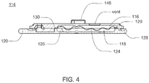
- base nub 120 and top nub 122 may be used as indicators of alignment and complete engagement.
- Cavity 116 may be at least partially formed by and integral to disposable housing assembly 114. Cavity 116 may include a membrane assembly 124 for at least partially defining reservoir 118. Reservoir 118 may be further defined by disposable housing assembly 114, e.g., by a recess 126 formed in base portion 128 of disposable housing assembly 114. For example, membrane assembly 124 may be disposed over recess 126 and attached to base portion 128, thereby forming reservoir 118. Membrane assembly 124 may be attached to base portion 128 by conventional means, such as gluing, heat sealing, and/or compression fitting, such that a seal 130 is formed between membrane assembly 124 and base portion 128.
- Membrane assembly 124 may be flexible and the space formed between membrane assembly 124 and recess 126 in base portion 128 may define reservoir 118. Reservoir 118 may be non-pressurized and in fluid communication with a fluid path (not shown). Membrane assembly 124 may be at least partially collapsible and cavity 116 may include a vent assembly, thereby advantageously preventing the buildup of a vacuum in reservoir 118 as the infusible fluid is delivered from reservoir 118 to the fluid path. In a preferred embodiment, membrane assembly 124 is fully collapsible, thus allowing for the complete delivery of the infusible fluid. Cavity 116 may be configured to provide sufficient space to ensure there is always some air space even when reservoir 118 is filled with infusible fluid.
- membranes and reservoirs described herein may be made from materials including but not limited to silicone, NITRILE, and any other material having desired resilience and properties for functioning as described herein. Additionally, other structures could serve the same purpose.
- a partially collapsible non pressurized reservoir may advantageously prevent the buildup of air in the reservoir as the fluid in the reservoir is depleted. Air buildup in a vented reservoir could prevent fluid egress from the reservoir, especially if the system is tilted so that an air pocket intervenes between the fluid contained in the reservoir and the septum of the reservoir. Tilting of the system is expected during normal operation as a wearable device.
- Reservoir 118 may be conveniently sized to hold an insulin supply sufficient for delivery over one or more days.
- reservoir 118 may hold about 1.00 to 3.00 ml of insulin.
- a 3.00 ml insulin reservoir may correspond to approximately a three day supply for about 90% of potential users.
- reservoir 118 may be any size or shape and may be adapted to hold any amount of insulin or other infusible fluid.
- the size and shape of cavity 116 and reservoir 118 is related to the type of infusible fluid that cavity 116 and reservoir 118 are adapted to hold.
- Disposable housing assembly 114 may include a support member 132 ( FIG. 3 ) configured to prevent accidental compression of reservoir 118. Compression of reservoir 118 may result in an unintentional dosage of infusible fluid being forced through the fluid path to the user.
- reusable housing assembly 102 and disposable housing assembly 114 may be constructed of a rigid material that is not easily compressible.
- support member 132 may be included within disposable housing assembly 114 to prevent compression of infusion pump assembly 100 and cavity 116 therein.
- Support member 132 may be a rigid projection from base portion 128.
- support member 132 may be disposed within cavity 116 and may prevent compression of reservoir 118.
- cavity 116 may be configured to provide sufficient space to ensure there is always some air space even when reservoir 118 is filled with infusible fluid. Accordingly, in the event that infusion pump assembly 100 is accidentally compressed, the infusible fluid may not be forced through cannula assembly 136 (e.g., shown in FIG. 9 ).
- Cavity 116 may include a septum assembly 146 ( FIG. 3 ) configured to allow reservoir 118 to be filled with the infusible fluid.
- Septum assembly 146 may be a conventional septum made from rubber or plastic and have a one-way fluid valve configured to allow a user to fill reservoir 118 from a syringe or other filling device.
- septum 146 may be located on the top of membrane assembly 124.
- cavity 116 may include a support structure (e.g., support member 132 in FIG. 3 ) for supporting the area about the back side of the septum so as to maintain the integrity of the septum seal when a needle is introducing infusible fluid into cavity 116.
- the support structure may be configured to support the septum while still allowing the introduction of the needle for introducing infusible fluid into cavity 116.
- Infusion pump assembly 100 may include an overfill prevention assembly (not shown) that may e.g., protrude into cavity 116 and may e.g., prevent the overfilling of reservoir 118.
- an overfill prevention assembly (not shown) that may e.g., protrude into cavity 116 and may e.g., prevent the overfilling of reservoir 118.
- reservoir 118 may be configured to be filled a plurality of times.
- reservoir 118 may be refillable through septum assembly 146.
- electronic control assembly 110 may monitor the fluid level of the infusible fluid in reservoir 118. When the fluid level reaches a low point, electronic control assembly 110 may provide a signal, such as a light or a vibration, to the user that reservoir 118 needs to be refilled.
- a syringe, or other filling device may be used to fill reservoir 118 through septum 146.
- Reservoir 118 may be configured to be filled a single time.
- a refill prevention assembly (not shown) may be utilized to prevent the refilling of reservoir 118, such that disposable housing assembly 114 may only be used once.
- the refill prevention assembly (not shown) may be a mechanical device or an electro-mechanical device.
- insertion of a syringe into septum assembly 146 for filling reservoir 118 may trigger a shutter to close over septum 146 after a single filling, thus preventing future access to septum 146.
- a sensor may indicate to electronic control assembly 110 that reservoir 118 has been filled once and may trigger a shutter to close over septum 146 after a single filling, thus preventing future access to septum 146.
- Other means of preventing refilling may be utilized and are considered to be within the scope of this disclosure.
- disposable housing assembly 114 may include septum assembly 146 that may be configured to allow reservoir 118 to be filled with the infusible fluid.
- Septum assembly 146 may be a conventional septum made from rubber or any other material that may function as a septum, or, in other embodiments, septum assembly 146 may be, but is not limited to, a plastic, or other material, one-way fluid valve.
- septum assembly 146 is configured to allow a user to fill reservoir 118 from a syringe or other filling device.
- Disposable housing assembly 114 may include a septum access assembly that may be configured to limit the number of times that the user may refill reservoir 118.
- infusion pump assembly 100 may include an external infusion set 134 configured to deliver the infusible fluid to a user.
- External infusion set 134 may be in fluid communication with cavity 118, e.g. by way of the fluid path.
- External infusion set 134 may be disposed adjacent to infusion pump assembly 100.
- external infusion set 134 may be configured for application remote from infusion pump assembly 100, as discussed in greater detail below.
- External infusion set 134 may include a cannula assembly 136, which may include a needle or a disposable cannula 138, and tubing assembly 140.
- Tubing assembly 140 may be in fluid communication with reservoir 118, for example, by way of the fluid path, and with cannula assembly 138 for example, either directly or by way of a cannula interface 142.
- External infusion set 134 may be a tethered infusion set, as discussed above regarding application remote from infusion pump assembly 100.
- external infusion set 134 may be in fluid communication with infusion pump assembly 100 through tubing assembly 140, which may be of any length desired by the user (e.g., 3-18 inches).
- tubing assembly 140 may be of any length desired by the user (e.g., 3-18 inches).
- infusion pump assembly 100 may be worn on the skin of a user with the use of adhesive patch 144, the length of tubing assembly 140 may enable the user to alternatively wear infusion pump assembly 100 in a pocket. This may be beneficial to users whose skin is easily irritated by application of adhesive patch 144.
- wearing and/or securing infusion pump assembly 100 in a pocket may be preferable for users engaged in physical activity.
- a hook and loop fastener system (e.g. such as hook and loop fastener systems offered by Velcro USA Inc. of Manchester, NH) may be utilized to allow for easy attachment / removal of an infusion pump assembly (e.g., infusion pump assembly 100) from the user.
- adhesive patch 144 may be attached to the skin of the user and may include an outward facing hook or loop surface.
- the lower surface of disposable housing assembly 114 may include a complementary hook or loop surface.
- the strength of the hook and loop connection may be stronger than the strength of the adhesive to skin connection. Accordingly, various hook and loop surface patterns may be utilized to regulate the strength of the hook and loop connection.
- the infusion pump assembly may be wirelessly controlled by a remote control device.
- a split ring resonator antenna may be used for wireless communication between the infusion pump assembly and the remote control device (or other remote device).
- the term "wirelessly controlled” refers to any device that may receive input, instructions, data, or other, wirelessly.
- a wirelessly controlled insulin pump refers to any insulin pump that may wirelessly transmit and/or receive data from another device.
- an insulin pump may both receive instructions via direct input by a user and may receive instructions wirelessly from a remote controller.
- an exemplary embodiment of a split ring resonator antenna adapted for use in a wirelessly controlled medical device, and is used in the exemplary embodiment of the infusion pump assembly, includes at least one split ring resonator antenna (hereinafter “SRR antenna”) 2508, a wearable electric circuit, such as a wirelessly controlled medical infusion apparatus (hereinafter “infusion apparatus”) 2514, capable of powering the antenna, and a control unit 2522.
- SRR antenna split ring resonator antenna
- infusion apparatus wirelessly controlled medical infusion apparatus
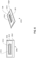
- a SRR antenna 2508 may reside on the surface of a nonconducting substrate base 2520, allowing a metallic layer (or layers) to resonate at a predetermined frequency.
- the substrate base 2520 may be composed of standard printed circuit board material such as Flame Retardant 2 (FR-2), FR-3, FR-4, FR-5, FR-6, G-10, CEM-1, CEM-2, CEM-3, CEM-4, CEM-5, Polyimide, Teflon, ceramics, or flexible Mylar.
- the metallic resonating bodies comprising a SRR antenna 2508 may be made of two rectangular metallic layers 2502, 2504, made of, for example, platinum, iridium, copper, nickel, stainless steel, silver or other conducting materials. In other various embodiments, a SRR antenna 2508 may contain only one metallic resonating body.
- a gold-plated copper outer layer 2502 surrounds, without physically contacting, a gold-plated copper inner ring 2504. That is, the inner ring 2504 resides in the cavity 2510 (or aperture) formed by the outer layer 2502.
- the inner ring 2504 may contain a gap, or split 2506, along its surface completely severing the material to form an incomplete ring shape.
- Both metallic resonating bodies 2502, 2504 may reside on the same planar surface of the substrate base 2520.
- the outer layer 2502 may by driven via a transmission line 2512 coupled to the outer layer 2502, for example. Additionally, in various other embodiments, a transmission line 2512 may be coupled to the inner ring 2504.
- Antenna design software such as AWR Microwave Office, capable of simulating electromagnetic geometries, such as, antenna performance, may significantly decrease the time required to produce satisfactory dimensions compared to physically fabricating and testing antennas.
- the SRR antenna 2508 may be designed such that the geometric dimensions of the resonant bodies 2502, 2504 facilitate an operational frequency of the 2.4GHz ISM Band.
- FIG. 132 depicts the exemplary dimensions of the inner ring 2504 and outer layer 2502, and the positioning of the cavity 2510 in which the inner ring 2504 resides.
- the distance in between the outer layer 2502 and the inner ring 2504 is a constant 0.005 inches along the perimeter of the cavity 2510.
- the distance between the outer layer and the inner ring may vary and in some embodiments, the operational frequency may vary.
- a SRR antenna 2508 may have dimensions such that it could be categorized as electrically small, that is, the greatest dimension of the antenna being less than one wavelength at operational frequency.
- a SRR antenna 2508 may be composed of one or more alternatively-shaped metallic outer layers, such as circular, pentagonal, octagonal, or hexagonal, surrounding one or more metallic inner layers of similar shape. Further, in various other embodiments, one or more metallic layers of a SRR antenna 2508 may contain gaps in the material.
- a SRR antenna 2508 having the exemplary geometry exhibits acceptable return loss and frequency values when placed in contact with human skin.
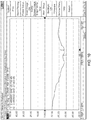
- return loss prior to contact with human skin is near -15 dB while monitoring a frequency band centered around the 2.44 GHz ISM Band.
- Return loss during contact with human skin remains a suitable value near -25 dB at the same frequency, yielding approximately 97% transmission power.
- Return loss of an Inverted-F antenna may exhibit a difference when the antenna contacts human skin, resulting in a low percentage of power transmitted outward from the antenna.
- return loss of an Inverted-F antenna prior to contact with human skin is near -25 dB at a frequency centered around 2.44 GHz.
- Return loss during contact with human skin is nearly -2 dB at the same frequency, yielding approximately 37% power transmission.
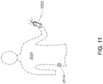
- one application of a SRR antenna 2508 may be integration into a wearable infusion apparatus 2514 capable of delivering fluid medication to a user/patient 2524.
- the safety of the user/patient is dependent on fluid operation between these electrical components, thus reliable wireless transmission to and from a control unit 2522 is of great importance.
- An infusion apparatus 2514 may be worn directly on the human body.
- such a device may be attached on or above the hip joint in direct contact with human skin, placing the SRR antenna 2508 at risk of unintended dielectric loading causing a frequency shift in electrical operation.
- electrical characteristics of the SRR antenna 2508 which allow it to be less sensitive to surrounding materials are beneficial in reducing or eliminating degradation to the performance.
- a controlling component such as a control unit 2522 (generally shown in FIG. 11 ), may be paired with an infusion apparatus 2514, and may be designed to transmit and receive wireless signals to and from the infusion apparatus 2514 at a predetermined frequency band, which, in the exemplary embodiment, is the 2.4GHz Industrial Scientific and Medical Band ("ISM band").
- the control unit 2522 serves as the main user interface through which a patient or third party may manage insulin delivery.
- infusion apparatus 2514 may utilize a SRR antenna 2508 to communicate with one or more control units 2522.
- a number of different wireless communication protocols may be used in conjunction with the SRR antenna 2508, as the protocol and data types to be transferred are independent of the electrical characteristics of the antenna.
- a bi-directional master/slave means of communication organizes the data transfer through the SRR antenna 2508.
- the control unit 2522 may act as the master by periodically polling the infusion apparatus 2514, or slave, for information. In the exemplary embodiment, only when the slave is polled, the slave may send signals to the control unit 2522 only when the slave is polled. However, in other embodiments, the slave may send signals before being polled.
- Signals sent by way of this system may include, but are not limited to, control, alarm, status, patient treatment profile, treatment logs, channel selection and negotiation, handshaking, encryption, and check-sum.
- transmission through the SRR antenna 2508 may also be halted during certain infusion operations as an added precaution against electrical disruption of administration of insulin to the patient.
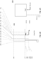
- the SRR antenna 2508 may be coupled to electrical source circuitry via one or more pins 2516 on a transmission line 2512.
- a transmission line may comprise a wire, pairs of wire, or other controlled impedance methods providing a signal path to the SRR antenna 2508.
- the transmission line 2512 may reside on the surface of the substrate base 2520 and may be composed of the same material as the SRR antenna 2508, such as gold-plated copper. Additionally, a ground plane may be attached to the surface of the substrate base opposite the transmission line 2512.
- the electrical circuitry coupled to the SRR antenna 2508 may apply an RF signal to the end of the transmission line 2512 nearest the circuitry, creating an electromagnetic field throughout, and propagating from, the SRR antenna 2508.
- the electrical circuitry coupled to the SRR antenna 2508 facilitates resonance at a predetermined frequency band, which, in the exemplary embodiment, is the 2.4GHz ISM band.
- transmission line 2512 and SRR antenna 2508 both have impedances of 50 Ohms to simplify circuit simulation and characterization.
- the transmission line and SRR antenna 2508 may have other impendence values, or a different resonating frequency.
- a signal processing component(s) 2518 such as, a filter, amplifier, or switch, may be integrated into the transmission line 2512, or at some point between the signal source connection pins 2516 and the SRR antenna 2508.
- the signal processing component 2518 is a band-pass filter to facilitate desired signal processing, such as, allowing only the exemplary frequency band to be transmitted to the antenna, and rejecting frequencies outside that range.
- a Combline band-pass filter 2518 may be included in the transmission line 2512 between the antenna and the signal source.
- any other signal processing device for example, but not limited to, filters, amplifiers, or any other signal processing devices known in the art.
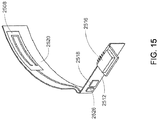
- a SRR antenna 2508 may be composed of metallic bodies capable of resonating on a flexible or rigid substrate. As shown in FIG. 7 and FIG. 8 , the exemplary embodiment incorporates a curved SRR antenna on a flexible Polyimide substrate 2520. Polyimide may be the exemplary material because it tends to be more flexible than alternative substrates. This configuration may allow for simplified integration into circular-shaped devices (such as a wirelessly controlled medical infusion apparatus 2514), devices with irregular-shaped external housing, or devices in which saving space is paramount.
- both control unit 2522 and base unit 2514 may incorporate a SRR antenna 2508. This configuration may prove beneficial where the control unit is meant to be handheld, in close proximity to human skin, or is likely to be in close proximity to a varying number of materials with varying dielectric constants.
- an impedance matching circuit 2526 may be integrated into the transmission line 2512.
- the impedance matching circuit 2526 may be integrated between the signal processing component(s) 2518 and the SRR antenna 2508.
- the embodiments including an impedance matching circuit 2526 eliminate the need for a ground plane for the SRR antenna 2508.
- FIGS. 135A and 135B outline drawings, showing the dimensions and the mechanical configuration, respectively, for one embodiment of the impedance matching circuit 2526 are shown. The dimensions shown in these FIGS. are for one embodiment of the impedance matching circuit 2526. However, in other embodiments, the dimensions may be different than those shown in FIGS. 16 and 17 .
- the dimensions used may depend on one or more factors, including, but not limited to, the thickness of the substrate 2512 and/or the material/ dielectric constant of the substrate 2512. For example, where a substrate has a lower dielectric constant, the geometry of the impedance matching circuit 2526 may be larger, and where the dielectric constant is higher, the geometry of the impedance matching circuit 2526 may be smaller.
- the size of the device in which the SRR antenna 2508 may be used may influence the substrate selected, i.e., the size of the device may influence the design of the impedance matching circuit 2526.
- the thickness of the substrate may influence the design, and in some embodiments, the shape of the substrate may change the design.
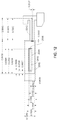
- FIG. 18 a diagram of the dimensions of the inner and outer portion of the exemplary embodiment of the SRR antenna, including an impedance matching circuit, is shown.
- the dimensions shown in FIGS. 132 and 136 are for one embodiment of the SRR antenna design. However, in other embodiments, the dimensions may be different than those shown in FIGS. 12 and 18 .
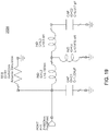
- FIG. 19 a schematic of one embodiment of the matching circuit, as shown in FIGS. 135A and 135B, is shown.
- the component values shown are representative of the geometry of the impendence matching circuit 2526 as shown in FIGS. 135A and 135B.
- the component values may vary with the impendence matching circuit 2526 design and/or geometry.
- FIGS. 20 and 21 another embodiment of the impedance matching circuit 2526 is shown.
- FIG. 22 a schematic of one embodiment of the matching circuit, as shown in FIGS. 20 and 21 , is shown.
- the component values shown are representative of the geometry of the impendence matching circuit 2526 as shown in FIGS. 20 and 21 .
- the component values may vary with the impendence matching circuit 2526 design and/or geometry.
- the design of the impendence matching circuit 2526 may vary.
- a SRR antenna 2508 may be integrated into a human or animal limb replacement.
- the electrical systems developed to control and simulate muscle movements require much more wiring and data transfer among subsystems. Wireless data transfer within a prosthetic limb may reduce weight through reduced physical wiring, conserve space, and allow greater freedom of movement.
- common antennas in such a system may be susceptible to dielectric loading.
- a prosthetic limb such as a robotic arm, may also come into contact with human skin or other dielectric materials and benefit from the reduction of electrical disturbances associated with such an antenna.
- the SRR antenna 2508 may be integrated into any device comprised of the electrical components capable of powering and transmitting/receiving data to an antenna and susceptible to electrical disturbances associated with proximity to dielectric materials.
- a SRR antenna 2508 may be integrated into a configuration of medical components in which one or more implantable medical devices, operating within the human body, communicate wirelessly to a handheld, body-mounted, or remote control unit.
- both body-mounted and in-body wireless devices may utilize a SRR antenna 2508 for wireless communication.
- one or more of the components utilizing a SRR antenna 2508 may be completely surrounded by human skin, tissue or other dielectric material.
- such a configuration may be used in conjunction with a heart monitoring/control system where stability and consistency of wireless data transmission are of fundamental concern.
- a SRR antenna 2508 may be integrated into the embodiments of the infusion pump assembly.
- the SRR antenna 2508 may be integrated into a configuration of medical components in which one or more electrical sensors positioned on, or attached to, the human body wirelessly communicate to a remote transceiving unit.
- a plurality of electrodes positioned on the body may be coupled to a wireless unit employing a SRR antenna 2508 for wireless transmission to a remotely located electrocardiogram machine.
- a wireless temperature sensor in contact with human skin may employ SRR antenna 2508 for wireless communication to a controller unit for temperature regulation of the room in which the sensor resides.
Description
- This application relates generally to split ring resonator antennas and more particularly to a split ring resonator antenna adapted for use in wirelessly controlled medical device
- Many potentially valuable medicines or compounds, including biologicals, are not orally active due to poor absorption, hepatic metabolism or other pharmacokinetic factors. Additionally, some therapeutic compounds, although they can be orally absorbed, are sometimes required to be administered so often it is difficult for a patient to maintain the desired schedule. In these cases, parenteral delivery is often employed or could be employed.
- Effective parenteral routes of drug delivery, as well as other fluids and compounds, such as subcutaneous injection, intramuscular injection, and intravenous (IV) administration include puncture of the skin with a needle or stylet. Insulin is an example of a therapeutic fluid that is self-injected by millions of diabetic patients. Users of parenterally delivered drugs may benefit from a wearable device that would automatically deliver needed drugs/compounds over a period of time.
- To this end, there have been efforts to design portable and wearable devices for the controlled release of therapeutics. Such devices are known to have a reservoir such as a cartridge, syringe, or bag, and to be electronically controlled. These devices suffer from a number of drawbacks including the malfunction rate. Reducing the size, weight and cost of these devices is also an ongoing challenge. Additionally, these devices often apply to the skin and pose the challenge of frequent re-location for application.
- In accordance with one aspect of the present invention an infusion pump assembly is disclosed. The infusion pump assembly includes a reservoir for receiving an infusible fluid, a pump assembly for pumping a quantity of infusible fluid from the reservoir to an exit, a first valve assembly configured to selectively isolate the pump assembly from the reservoir, a second valve assembly configured to selectively isolate the exit from the pumping assembly, and a split ring resonator antenna having a resonant frequency comprising a plurality of planar metallic layers.
- Some embodiments of this aspect of the invention include one or more of the following. Wherein the split ring resonator antenna further includes an impedance matching circuit. Wherein the infusion pump assembly further includes at least one control unit and a transmitting and receiving base unit capable of powering the antenna. The split ring resonator antenna is coupled to the base unit and whereby the antenna wirelessly transmits and receives data from the at least one control unit, whereby the system minimizes the parasitic effects of dielectric materials in close proximity to a wearable radio frequency device. Wherein the apparatus further includes a signal processing component. wherein the signal processing component further comprising at least one filter. wherein the signal processing component further comprising at least one amplifier. wherein the signal processing component further comprising at least one switch. Wherein the infusion pump assembly further includes an external infusion set configured to deliver the infusible fluid to a user. Wherein the infusion pump assembly further includes a disposable housing assembly including the reservoir and a reusable housing assembly including a second portion of the fluid delivery system.
- The details of one or more embodiments are set forth in the accompanying drawings and the description below. Other features and advantages will become apparent from the description, the drawings, and the claims.
-
-
FIG. 1 is a side view of an infusion pump assembly; -
FIG. 2 is a perspective view of the infusion pump assembly ofFIG. 1 ; -
FIG. 3 is an exploded view of various components of the infusion pump assembly ofFIG. 1 ; -
FIG. 4 is a cross-sectional view of the disposable housing assembly of the infusion pump assembly ofFIG. 1 ; -
FIG. 5 is a perspective view of the infusion pump assembly ofFIG. 1 showing an external infusion set; -
FIG. 6 is an exemplary diagram of a split ring resonator antenna; -
FIG. 7 is an exemplary diagram of a medical device configured to utilize a split ring resonator antenna; -
FIG. 8 is an exemplary diagram of a split ring resonator antenna and transmission line from a medical infusion device; -
FIG. 9 is a graph of the return loss of a split ring resonator antenna prior to contact with human skin; -
FIG. 10 is a graph of the return loss of a split ring resonator antenna during contact with human skin; -
FIG. 11 is an exemplary diagram of a split ring resonator antenna integrated into a device which operates within close proximity to dielectric material; -
FIG. 12 is a diagram of the dimensions of the inner and outer portion of the exemplary embodiment; -
FIG. 13 is a graph of the return loss of a non-split ring resonator antenna prior to contact with human skin; -
FIG. 14 is a graph of the return loss of a non-split ring resonator antenna during contact with human skin; -
FIG. 15 is an exemplary diagram of another embodiment of the split ring resonator antenna and transmission line from a medical infusion device; -
FIG. 16 is an outline drawings of the dimensions of the exemplary embodiment of the impedance matching circuit; -
FIG. 17 is a connection illustration of the impedance matching circuit shown inFIG. 16 ; -
FIG. 18 is a diagram of the dimensions of the inner and outer portion of the exemplary embodiment including an impedance matching circuit; -
FIG. 19 is a schematic diagram of the impedance matching circuit shown inFIG. 16 ; -
FIG. 20 is an outline drawings of the dimensions of one embodiment of the impedance matching circuit; -
FIG. 21 is a connection illustration of the impedance matching circuit shown inFIG. 16 ; and -
FIG. 22 is a schematic diagram of the impedance matching circuit shown inFIG. 16 . - Like reference symbols in the various drawings indicate like elements.
- Referring to
FIGS. 1-3 , aninfusion pump assembly 100 may include areusable housing assembly 102.Reusable housing assembly 102 may be constructed from any suitable material, such as a hard or rigid plastic, that will resist compression. For example, use of durable materials and parts may improve quality and reduce costs by providing a reusable portion that lasts longer and is more durable, providing greater protection to components disposed therein. -
Reusable housing assembly 102 may includemechanical control assembly 104 having apump assembly 106 and at least onevalve assembly 108.Reusable housing assembly 102 may also includeelectrical control assembly 110 configured to provide one or more control signals tomechanical control assembly 104 and effectuate the basal and/or bolus delivery of an infusible fluid to a user.Disposable housing assembly 114 may includevalve assembly 108 which may be configured to control the flow of the infusible fluid through a fluid path.Reusable housing assembly 102 may also includepump assembly 106 which may be configured to pump the infusible fluid from the fluid path to the user. -
Electrical control assembly 110 may monitor and control the amount of infusible fluid that has been and/or is being pumped. For example,electrical control assembly 110 may receive signals fromvolume sensor assembly 148 and calculate the amount of infusible fluid that has just been dispensed and determine, based upon the dosage required by the user, whether enough infusible fluid has been dispensed. If enough infusible fluid has not been dispensed,electrical control assembly 110 may determine that more infusible fluid should be pumped.Electrical control assembly 110 may provide the appropriate signal tomechanical control assembly 104 so that any additional necessary dosage may be pumped orelectrical control assembly 110 may provide the appropriate signal tomechanical control assembly 104 so that the additional dosage may be dispensed with the next dosage. Alternatively, if too much infusible fluid has been dispensed,electrical control assembly 110 may provide the appropriate signal tomechanical control assembly 104 so that less infusible fluid may be dispensed in the next dosage. -
Mechanical control assembly 104 may include at least one shape-memory actuator 112.Pump assembly 106 and/orvalve assembly 108 ofmechanical control assembly 104 may be actuated by at least one shape-memory actuator, e.g., shape-memory actuator 112, which may be a shape-memory wire in wire or spring configuration.Shape memory actuator 112 may be operably connected to and activated byelectrical control assembly 110, which may control the timing and the amount of heat and/or electrical energy used to actuatemechanical control assembly 104.Shape memory actuator 112 may be, for example, a conductive shape-memory alloy wire that changes shape with temperature. The temperature of shape-memory actuator 112 may be changed with a heater, or more conveniently, by application of electrical energy.Shape memory actuator 112 may be a shape memory wire constructed of nickel/titanium alloy, such as NITINOL™ or FLEXINOL®. -
Infusion pump assembly 100 may include avolume sensor assembly 148 configured to monitor the amount of fluid infused byinfusion pump assembly 100. For example,volume sensor assembly 148 may employ, for example, acoustic volume sensing. Acoustic volume measurement technology is the subject ofU.S. Patent Nos. 5,575,310 and5,755,683 assigned to DEKA Products Limited Partnership, as well as U.S. patent application Publication Nos.US 2007/0228071 A1 ,US 2007/0219496 A1 ,US 2007/0219480 A1 ,US 2007/0219597 A1 , the entire disclosures of all of which are incorporated herein by reference. Other alternative techniques for measuring fluid flow may also be used; for example, Doppler-based methods; the use of Hall-effect sensors in combination with a vane or flapper valve; the use of a strain beam (for example, related to a flexible member over a fluid reservoir to sense deflection of the flexible member); the use of capacitive sensing with plates; or thermal time of flight methods. One such alternative technique is disclosed inU.S. Patent application Serial No. 11/704,899 Infusion pump assembly 100 may be configured so that the volume measurements produced byvolume sensor assembly 148 may be used to control, through a feedback loop, the amount of infusible fluid that is infused into the user. -
Infusion pump assembly 100 may further include adisposable housing assembly 114. For example,disposable housing assembly 114 may be configured for a single use or for use for a specified period of time, e.g., three days or any other amount of time.Disposable housing assembly 114 may be configured such that any components ininfusion pump assembly 100 that come in contact with the infusible fluid are disposed on and/or withindisposable housing assembly 114. For example, a fluid path or channel including a reservoir, may be positioned withindisposable housing assembly 114 and may be configured for a single use or for a specified number of uses before disposal. The disposable nature ofdisposable housing assembly 114 may improve sanitation ofinfusion pump assembly 100. - Referring also to
FIG. 4 ,disposable housing assembly 114 may be configured to releasably engagereusable housing assembly 102, and includes acavity 116 that has areservoir 118 for receiving an infusible fluid (not shown), e.g., insulin. Such releasable engagement may be accomplished by a screw-on, a twist-lock or a compression fit configuration, for example.Disposable housing assembly 114 and/orreusable housing assembly 102 may include an alignment assembly configured to assist in aligningdisposable housing assembly 114 andreusable housing assembly 102 for engagement in a specific orientation. Similarly,base nub 120 andtop nub 122 may be used as indicators of alignment and complete engagement. -
Cavity 116 may be at least partially formed by and integral todisposable housing assembly 114.Cavity 116 may include amembrane assembly 124 for at least partially definingreservoir 118.Reservoir 118 may be further defined bydisposable housing assembly 114, e.g., by arecess 126 formed inbase portion 128 ofdisposable housing assembly 114. For example,membrane assembly 124 may be disposed overrecess 126 and attached tobase portion 128, thereby formingreservoir 118.Membrane assembly 124 may be attached tobase portion 128 by conventional means, such as gluing, heat sealing, and/or compression fitting, such that aseal 130 is formed betweenmembrane assembly 124 andbase portion 128.Membrane assembly 124 may be flexible and the space formed betweenmembrane assembly 124 andrecess 126 inbase portion 128 may definereservoir 118.Reservoir 118 may be non-pressurized and in fluid communication with a fluid path (not shown).Membrane assembly 124 may be at least partially collapsible andcavity 116 may include a vent assembly, thereby advantageously preventing the buildup of a vacuum inreservoir 118 as the infusible fluid is delivered fromreservoir 118 to the fluid path. In a preferred embodiment,membrane assembly 124 is fully collapsible, thus allowing for the complete delivery of the infusible fluid.Cavity 116 may be configured to provide sufficient space to ensure there is always some air space even whenreservoir 118 is filled with infusible fluid. - The membranes and reservoirs described herein may be made from materials including but not limited to silicone, NITRILE, and any other material having desired resilience and properties for functioning as described herein. Additionally, other structures could serve the same purpose.
- The use of a partially collapsible non pressurized reservoir may advantageously prevent the buildup of air in the reservoir as the fluid in the reservoir is depleted. Air buildup in a vented reservoir could prevent fluid egress from the reservoir, especially if the system is tilted so that an air pocket intervenes between the fluid contained in the reservoir and the septum of the reservoir. Tilting of the system is expected during normal operation as a wearable device.
-
Reservoir 118 may be conveniently sized to hold an insulin supply sufficient for delivery over one or more days. For example,reservoir 118 may hold about 1.00 to 3.00 ml of insulin. A 3.00 ml insulin reservoir may correspond to approximately a three day supply for about 90% of potential users. In other embodiments,reservoir 118 may be any size or shape and may be adapted to hold any amount of insulin or other infusible fluid. In some embodiments, the size and shape ofcavity 116 andreservoir 118 is related to the type of infusible fluid thatcavity 116 andreservoir 118 are adapted to hold. -
Disposable housing assembly 114 may include a support member 132 (FIG. 3 ) configured to prevent accidental compression ofreservoir 118. Compression ofreservoir 118 may result in an unintentional dosage of infusible fluid being forced through the fluid path to the user. In a preferred embodiment,reusable housing assembly 102 anddisposable housing assembly 114 may be constructed of a rigid material that is not easily compressible. However, as an added precaution,support member 132 may be included withindisposable housing assembly 114 to prevent compression ofinfusion pump assembly 100 andcavity 116 therein.Support member 132 may be a rigid projection frombase portion 128. For example,support member 132 may be disposed withincavity 116 and may prevent compression ofreservoir 118. - As discussed above,
cavity 116 may be configured to provide sufficient space to ensure there is always some air space even whenreservoir 118 is filled with infusible fluid. Accordingly, in the event thatinfusion pump assembly 100 is accidentally compressed, the infusible fluid may not be forced through cannula assembly 136 (e.g., shown inFIG. 9 ). -
Cavity 116 may include a septum assembly 146 (FIG. 3 ) configured to allowreservoir 118 to be filled with the infusible fluid.Septum assembly 146 may be a conventional septum made from rubber or plastic and have a one-way fluid valve configured to allow a user to fillreservoir 118 from a syringe or other filling device. In some embodiments,septum 146 may be located on the top ofmembrane assembly 124. In these embodiments,cavity 116 may include a support structure (e.g.,support member 132 inFIG. 3 ) for supporting the area about the back side of the septum so as to maintain the integrity of the septum seal when a needle is introducing infusible fluid intocavity 116. The support structure may be configured to support the septum while still allowing the introduction of the needle for introducing infusible fluid intocavity 116. -
Infusion pump assembly 100 may include an overfill prevention assembly (not shown) that may e.g., protrude intocavity 116 and may e.g., prevent the overfilling ofreservoir 118. - In some embodiments,
reservoir 118 may be configured to be filled a plurality of times. For example,reservoir 118 may be refillable throughseptum assembly 146. As infusible fluid may be dispensed to a user,electronic control assembly 110 may monitor the fluid level of the infusible fluid inreservoir 118. When the fluid level reaches a low point,electronic control assembly 110 may provide a signal, such as a light or a vibration, to the user thatreservoir 118 needs to be refilled. A syringe, or other filling device, may be used to fillreservoir 118 throughseptum 146. -
Reservoir 118 may be configured to be filled a single time. For example, a refill prevention assembly (not shown) may be utilized to prevent the refilling ofreservoir 118, such thatdisposable housing assembly 114 may only be used once. The refill prevention assembly (not shown) may be a mechanical device or an electro-mechanical device. For example, insertion of a syringe intoseptum assembly 146 for fillingreservoir 118 may trigger a shutter to close overseptum 146 after a single filling, thus preventing future access toseptum 146. Similarly, a sensor may indicate toelectronic control assembly 110 thatreservoir 118 has been filled once and may trigger a shutter to close overseptum 146 after a single filling, thus preventing future access toseptum 146. Other means of preventing refilling may be utilized and are considered to be within the scope of this disclosure. - As discussed above,
disposable housing assembly 114 may includeseptum assembly 146 that may be configured to allowreservoir 118 to be filled with the infusible fluid.Septum assembly 146 may be a conventional septum made from rubber or any other material that may function as a septum, or, in other embodiments,septum assembly 146 may be, but is not limited to, a plastic, or other material, one-way fluid valve. In various embodiments, including the exemplary embodiment,septum assembly 146 is configured to allow a user to fillreservoir 118 from a syringe or other filling device.Disposable housing assembly 114 may include a septum access assembly that may be configured to limit the number of times that the user may refillreservoir 118. - Referring also to
FIG. 5 ,infusion pump assembly 100 may include an external infusion set 134 configured to deliver the infusible fluid to a user. External infusion set 134 may be in fluid communication withcavity 118, e.g. by way of the fluid path. External infusion set 134 may be disposed adjacent toinfusion pump assembly 100. Alternatively, external infusion set 134 may be configured for application remote frominfusion pump assembly 100, as discussed in greater detail below. External infusion set 134 may include acannula assembly 136, which may include a needle or adisposable cannula 138, andtubing assembly 140.Tubing assembly 140 may be in fluid communication withreservoir 118, for example, by way of the fluid path, and withcannula assembly 138 for example, either directly or by way of acannula interface 142. - External infusion set 134 may be a tethered infusion set, as discussed above regarding application remote from
infusion pump assembly 100. For example, external infusion set 134 may be in fluid communication withinfusion pump assembly 100 throughtubing assembly 140, which may be of any length desired by the user (e.g., 3-18 inches). Thoughinfusion pump assembly 100 may be worn on the skin of a user with the use ofadhesive patch 144, the length oftubing assembly 140 may enable the user to alternatively wearinfusion pump assembly 100 in a pocket. This may be beneficial to users whose skin is easily irritated by application ofadhesive patch 144. Similarly, wearing and/or securinginfusion pump assembly 100 in a pocket may be preferable for users engaged in physical activity. - In addition to / as an alternative to
adhesive patch 144, a hook and loop fastener system (e.g. such as hook and loop fastener systems offered by Velcro USA Inc. of Manchester, NH) may be utilized to allow for easy attachment / removal of an infusion pump assembly (e.g., infusion pump assembly 100) from the user. Accordingly,adhesive patch 144 may be attached to the skin of the user and may include an outward facing hook or loop surface. Additionally, the lower surface ofdisposable housing assembly 114 may include a complementary hook or loop surface. Depending upon the separation resistance of the particular type of hook and loop fastener system employed, it may be possible for the strength of the hook and loop connection to be stronger than the strength of the adhesive to skin connection. Accordingly, various hook and loop surface patterns may be utilized to regulate the strength of the hook and loop connection. - In the exemplary embodiments, the infusion pump assembly may be wirelessly controlled by a remote control device. In the exemplary embodiments, a split ring resonator antenna may be used for wireless communication between the infusion pump assembly and the remote control device (or other remote device). The term "wirelessly controlled" refers to any device that may receive input, instructions, data, or other, wirelessly. Further, a wirelessly controlled insulin pump refers to any insulin pump that may wirelessly transmit and/or receive data from another device. Thus, for example, an insulin pump may both receive instructions via direct input by a user and may receive instructions wirelessly from a remote controller.
- Referring to
FIG. 6 an exemplary embodiment of a split ring resonator antenna adapted for use in a wirelessly controlled medical device, and is used in the exemplary embodiment of the infusion pump assembly, includes at least one split ring resonator antenna (hereinafter "SRR antenna") 2508, a wearable electric circuit, such as a wirelessly controlled medical infusion apparatus (hereinafter "infusion apparatus") 2514, capable of powering the antenna, and acontrol unit 2522. - In various embodiments, a
SRR antenna 2508 may reside on the surface of anonconducting substrate base 2520, allowing a metallic layer (or layers) to resonate at a predetermined frequency. Thesubstrate base 2520 may be composed of standard printed circuit board material such as Flame Retardant 2 (FR-2), FR-3, FR-4, FR-5, FR-6, G-10, CEM-1, CEM-2, CEM-3, CEM-4, CEM-5, Polyimide, Teflon, ceramics, or flexible Mylar. The metallic resonating bodies comprising aSRR antenna 2508 may be made of two rectangularmetallic layers SRR antenna 2508 may contain only one metallic resonating body. - In the exemplary embodiment, a gold-plated
copper outer layer 2502, surrounds, without physically contacting, a gold-plated copperinner ring 2504. That is, theinner ring 2504 resides in the cavity 2510 (or aperture) formed by theouter layer 2502. Theinner ring 2504 may contain a gap, or split 2506, along its surface completely severing the material to form an incomplete ring shape. Both metallic resonatingbodies substrate base 2520. In such a configuration, theouter layer 2502 may by driven via atransmission line 2512 coupled to theouter layer 2502, for example. Additionally, in various other embodiments, atransmission line 2512 may be coupled to theinner ring 2504. - Antenna design software, such as AWR Microwave Office, capable of simulating electromagnetic geometries, such as, antenna performance, may significantly decrease the time required to produce satisfactory dimensions compared to physically fabricating and testing antennas. Accordingly, with aid of such software, the
SRR antenna 2508 may be designed such that the geometric dimensions of theresonant bodies inner ring 2504 andouter layer 2502, and the positioning of thecavity 2510 in which theinner ring 2504 resides. The distance in between theouter layer 2502 and theinner ring 2504 is a constant 0.005 inches along the perimeter of thecavity 2510. However, in other embodiments, the distance between the outer layer and the inner ring may vary and in some embodiments, the operational frequency may vary. - In various embodiments, a
SRR antenna 2508 may have dimensions such that it could be categorized as electrically small, that is, the greatest dimension of the antenna being less than one wavelength at operational frequency. - In various other embodiments, a
SRR antenna 2508 may be composed of one or more alternatively-shaped metallic outer layers, such as circular, pentagonal, octagonal, or hexagonal, surrounding one or more metallic inner layers of similar shape. Further, in various other embodiments, one or more metallic layers of aSRR antenna 2508 may contain gaps in the material. - Referring to
FIG. 9 , aSRR antenna 2508 having the exemplary geometry exhibits acceptable return loss and frequency values when placed in contact with human skin. As shown in FIG. 130, focusing on the band of interest denoted bymarkers FIG. 10 , remains a suitable value near -25 dB at the same frequency, yielding approximately 97% transmission power. - These results are favorable especially as compared with a non-split ring resonator antenna type, such as the Inverted-F. Return loss of an Inverted-F antenna may exhibit a difference when the antenna contacts human skin, resulting in a low percentage of power transmitted outward from the antenna. By way of example, as shown in
FIG. 13 , and again focusing on the band of interest denoted bymarkers - In the exemplary embodiment, referring to
FIG. 12 andFIG. 7 , one application of aSRR antenna 2508 may be integration into awearable infusion apparatus 2514 capable of delivering fluid medication to a user/patient 2524. In such an application, the safety of the user/patient is dependent on fluid operation between these electrical components, thus reliable wireless transmission to and from acontrol unit 2522 is of great importance. - An
infusion apparatus 2514 may be worn directly on the human body. By way of example, such a device may be attached on or above the hip joint in direct contact with human skin, placing theSRR antenna 2508 at risk of unintended dielectric loading causing a frequency shift in electrical operation. However, in such an application, electrical characteristics of theSRR antenna 2508 which allow it to be less sensitive to surrounding materials are beneficial in reducing or eliminating degradation to the performance. A controlling component, such as a control unit 2522 (generally shown inFIG. 11 ), may be paired with aninfusion apparatus 2514, and may be designed to transmit and receive wireless signals to and from theinfusion apparatus 2514 at a predetermined frequency band, which, in the exemplary embodiment, is the 2.4GHz Industrial Scientific and Medical Band ("ISM band"). In the exemplary embodiment, thecontrol unit 2522 serves as the main user interface through which a patient or third party may manage insulin delivery. In other embodiments,infusion apparatus 2514 may utilize aSRR antenna 2508 to communicate with one ormore control units 2522. - In various embodiments, a number of different wireless communication protocols may be used in conjunction with the
SRR antenna 2508, as the protocol and data types to be transferred are independent of the electrical characteristics of the antenna. However, in the exemplary embodiment, a bi-directional master/slave means of communication organizes the data transfer through theSRR antenna 2508. Thecontrol unit 2522 may act as the master by periodically polling theinfusion apparatus 2514, or slave, for information. In the exemplary embodiment, only when the slave is polled, the slave may send signals to thecontrol unit 2522 only when the slave is polled. However, in other embodiments, the slave may send signals before being polled. Signals sent by way of this system may include, but are not limited to, control, alarm, status, patient treatment profile, treatment logs, channel selection and negotiation, handshaking, encryption, and check-sum. In some embodiments, transmission through theSRR antenna 2508 may also be halted during certain infusion operations as an added precaution against electrical disruption of administration of insulin to the patient. - In the exemplary embodiment, the
SRR antenna 2508 may be coupled to electrical source circuitry via one ormore pins 2516 on atransmission line 2512. In various other embodiments a transmission line may comprise a wire, pairs of wire, or other controlled impedance methods providing a signal path to theSRR antenna 2508. Thetransmission line 2512 may reside on the surface of thesubstrate base 2520 and may be composed of the same material as theSRR antenna 2508, such as gold-plated copper. Additionally, a ground plane may be attached to the surface of the substrate base opposite thetransmission line 2512. - The electrical circuitry coupled to the
SRR antenna 2508 may apply an RF signal to the end of thetransmission line 2512 nearest the circuitry, creating an electromagnetic field throughout, and propagating from, theSRR antenna 2508. The electrical circuitry coupled to theSRR antenna 2508 facilitates resonance at a predetermined frequency band, which, in the exemplary embodiment, is the 2.4GHz ISM band. Preferably,transmission line 2512 andSRR antenna 2508 both have impedances of 50 Ohms to simplify circuit simulation and characterization. However, in other various embodiments, the transmission line andSRR antenna 2508 may have other impendence values, or a different resonating frequency. - Referring to
FIG. 8 , a signal processing component(s) 2518, such as, a filter, amplifier, or switch, may be integrated into thetransmission line 2512, or at some point between the signal source connection pins 2516 and theSRR antenna 2508. In the exemplary embodiment, thesignal processing component 2518 is a band-pass filter to facilitate desired signal processing, such as, allowing only the exemplary frequency band to be transmitted to the antenna, and rejecting frequencies outside that range. In the exemplary embodiment, a Combline band-pass filter 2518 may be included in thetransmission line 2512 between the antenna and the signal source. However in other embodiments, any other signal processing device, for example, but not limited to, filters, amplifiers, or any other signal processing devices known in the art. - In various embodiments, a
SRR antenna 2508 may be composed of metallic bodies capable of resonating on a flexible or rigid substrate. As shown inFIG. 7 andFIG. 8 , the exemplary embodiment incorporates a curved SRR antenna on aflexible Polyimide substrate 2520. Polyimide may be the exemplary material because it tends to be more flexible than alternative substrates. This configuration may allow for simplified integration into circular-shaped devices (such as a wirelessly controlled medical infusion apparatus 2514), devices with irregular-shaped external housing, or devices in which saving space is paramount. - In various embodiments, both
control unit 2522 andbase unit 2514 may incorporate aSRR antenna 2508. This configuration may prove beneficial where the control unit is meant to be handheld, in close proximity to human skin, or is likely to be in close proximity to a varying number of materials with varying dielectric constants. - Referring now to
FIG. 15 , in various embodiments, animpedance matching circuit 2526 may be integrated into thetransmission line 2512. In some embodiments, theimpedance matching circuit 2526 may be integrated between the signal processing component(s) 2518 and theSRR antenna 2508. The embodiments including animpedance matching circuit 2526 eliminate the need for a ground plane for theSRR antenna 2508. Referring now to FIGS. 135A and 135B, outline drawings, showing the dimensions and the mechanical configuration, respectively, for one embodiment of theimpedance matching circuit 2526 are shown. The dimensions shown in these FIGS. are for one embodiment of theimpedance matching circuit 2526. However, in other embodiments, the dimensions may be different than those shown inFIGS. 16 and 17 . The dimensions used may depend on one or more factors, including, but not limited to, the thickness of thesubstrate 2512 and/or the material/ dielectric constant of thesubstrate 2512. For example, where a substrate has a lower dielectric constant, the geometry of theimpedance matching circuit 2526 may be larger, and where the dielectric constant is higher, the geometry of theimpedance matching circuit 2526 may be smaller. In some embodiments, the size of the device in which theSRR antenna 2508 may be used may influence the substrate selected, i.e., the size of the device may influence the design of theimpedance matching circuit 2526. For example, in some embodiments, the thickness of the substrate may influence the design, and in some embodiments, the shape of the substrate may change the design. - Referring now to
FIG. 18 , a diagram of the dimensions of the inner and outer portion of the exemplary embodiment of the SRR antenna, including an impedance matching circuit, is shown. The dimensions shown in FIGS. 132 and 136 are for one embodiment of the SRR antenna design. However, in other embodiments, the dimensions may be different than those shown inFIGS. 12 and18 . - Referring now to
FIG. 19 , a schematic of one embodiment of the matching circuit, as shown in FIGS. 135A and 135B, is shown. The component values shown are representative of the geometry of theimpendence matching circuit 2526 as shown in FIGS. 135A and 135B. The component values may vary with theimpendence matching circuit 2526 design and/or geometry. - Referring now to
FIGS. 20 and 21 , another embodiment of theimpedance matching circuit 2526 is shown. Referring now toFIG. 22 , a schematic of one embodiment of the matching circuit, as shown inFIGS. 20 and 21 , is shown. The component values shown are representative of the geometry of theimpendence matching circuit 2526 as shown inFIGS. 20 and 21 . The component values may vary with theimpendence matching circuit 2526 design and/or geometry. In various embodiments, the design of theimpendence matching circuit 2526 may vary. - In various other embodiments, a
SRR antenna 2508 may be integrated into a human or animal limb replacement. As prosthetic limbs are becoming more sophisticated the electrical systems developed to control and simulate muscle movements require much more wiring and data transfer among subsystems. Wireless data transfer within a prosthetic limb may reduce weight through reduced physical wiring, conserve space, and allow greater freedom of movement. However, common antennas in such a system may be susceptible to dielectric loading. Similar to the previously mentioned benefits of integrating aSRR antenna 2508 into a wirelessly controlled medical infusion apparatus, a prosthetic limb, such as a robotic arm, may also come into contact with human skin or other dielectric materials and benefit from the reduction of electrical disturbances associated with such an antenna. In other various embodiments, theSRR antenna 2508 may be integrated into any device comprised of the electrical components capable of powering and transmitting/receiving data to an antenna and susceptible to electrical disturbances associated with proximity to dielectric materials. - In various embodiments, a
SRR antenna 2508 may be integrated into a configuration of medical components in which one or more implantable medical devices, operating within the human body, communicate wirelessly to a handheld, body-mounted, or remote control unit. In certain embodiments, both body-mounted and in-body wireless devices may utilize aSRR antenna 2508 for wireless communication. Additionally, one or more of the components utilizing aSRR antenna 2508 may be completely surrounded by human skin, tissue or other dielectric material. By way of example, such a configuration may be used in conjunction with a heart monitoring/control system where stability and consistency of wireless data transmission are of fundamental concern. - In various other embodiments, a
SRR antenna 2508 may be integrated into the embodiments of the infusion pump assembly. In some embodiments, theSRR antenna 2508 may be integrated into a configuration of medical components in which one or more electrical sensors positioned on, or attached to, the human body wirelessly communicate to a remote transceiving unit. By way of example, a plurality of electrodes positioned on the body may be coupled to a wireless unit employing aSRR antenna 2508 for wireless transmission to a remotely located electrocardiogram machine. By way of further example, a wireless temperature sensor in contact with human skin may employSRR antenna 2508 for wireless communication to a controller unit for temperature regulation of the room in which the sensor resides.
Claims (12)
- An infusion pump assembly
comprising:a reservoir (118) for receiving an infusible fluid;a pump assembly (106) for pumping a quantity of infusible fluid from the reservoir to an exit;a first valve assembly (108) configured to selectively isolate the pump assembly from the reservoir;a second valve assembly (108) configured to selectively isolate the exit from the pump assembly; anda split ring resonator antenna (2508) having a resonant frequency comprising a plurality of planar metallic layers,the split ring resonator antenna comprising an outer ring (2502), an inner ring (2504), wherein the inner ring (2504) is surrounded by the outer ring (2502) without physically contacting the outer ring, the inner ring having a split (2506) and
an impedance matching circuit (2526), wherein the impedance matching circuit is integrated into a transmission line. - The infusion pump assembly of claim 1 wherein the infusion pump assembly further comprising:at least one control unit (2522); anda transmitting and receiving base unit (2514) capable of powering the antenna, wherein the split ring resonator antenna is coupled to the base unit and whereby the antenna wirelessly transmits and receives data from the at least one control unit, whereby the system minimizes the parasitic effects of dielectric materials in close proximity to a wearable radio frequency device.
- The infusion pump assembly of claim 2 further comprising a signal processing component (2518).
- The infusion pump assembly of claim 3, wherein the impedance matching circuit (2526) is integrated adjacent to the signal processing component (2518).
- The infusion pump assembly of claim 4, the signal processing component (2518) further comprising at least one filter.
- The infusion pump assembly of claim 4, the signal processing component (2518) further comprising at least one amplifier.
- The infusion pump assembly of claim 4, the signal processing component (2518) further comprising at least one switch.
- The infusion pump assembly of claim 2 further comprising an external infusion set (134) configured to deliver the infusible fluid to a user.
- The infusion pump assembly of claim 1 or 8 further comprising:a disposable housing assembly (114) including a first portion of a fluid delivery system and the reservoir; anda reusable housing assembly (102) including a second portion of the fluid delivery system.
- The system of claim 1 wherein the signal processing component further comprising at least one filter.
- The system of claim 1 wherein the signal processing component further comprising at least one amplifier.
- The system of claim 1 wherein the signal processing component further comprising at least one switch.
Applications Claiming Priority (2)
| Application Number | Priority Date | Filing Date | Title |
|---|---|---|---|
| US14178108P | 2008-12-31 | 2008-12-31 | |
| PCT/US2009/069491 WO2010078207A1 (en) | 2008-12-31 | 2009-12-23 | Split ring resonator antenna adapted for use in wirelessly controlled medical device |
Publications (2)
| Publication Number | Publication Date |
|---|---|
| EP2381978A1 EP2381978A1 (en) | 2011-11-02 |
| EP2381978B1 true EP2381978B1 (en) | 2017-07-12 |
Family
ID=44561351
Family Applications (1)
| Application Number | Title | Priority Date | Filing Date |
|---|---|---|---|
| EP09801361.8A Active EP2381978B1 (en) | 2008-12-31 | 2009-12-23 | Split ring resonator antenna adapted for use in wirelessly controlled medical device |
Country Status (2)
| Country | Link |
|---|---|
| EP (1) | EP2381978B1 (en) |
| CA (1) | CA2750335C (en) |
Cited By (2)
| Publication number | Priority date | Publication date | Assignee | Title |
|---|---|---|---|---|
| US11167081B2 (en) | 2016-06-16 | 2021-11-09 | Smiths Medical Asd, Inc. | Assemblies and methods for infusion pump system administration sets |
| US11801342B2 (en) | 2017-07-19 | 2023-10-31 | Smiths Medical Asd, Inc. | Housing arrangements for infusion pumps |
-
2009
- 2009-12-23 EP EP09801361.8A patent/EP2381978B1/en active Active
- 2009-12-23 CA CA2750335A patent/CA2750335C/en active Active
Non-Patent Citations (1)
| Title |
|---|
| None * |
Cited By (2)
| Publication number | Priority date | Publication date | Assignee | Title |
|---|---|---|---|---|
| US11167081B2 (en) | 2016-06-16 | 2021-11-09 | Smiths Medical Asd, Inc. | Assemblies and methods for infusion pump system administration sets |
| US11801342B2 (en) | 2017-07-19 | 2023-10-31 | Smiths Medical Asd, Inc. | Housing arrangements for infusion pumps |
Also Published As
| Publication number | Publication date |
|---|---|
| EP2381978A1 (en) | 2011-11-02 |
| CA2750335A1 (en) | 2010-07-08 |
| CA2750335C (en) | 2017-06-27 |
Similar Documents
| Publication | Publication Date | Title |
|---|---|---|
| EP1335764B1 (en) | Device and system for patient infusion | |
| EP1332440B1 (en) | Data collection assembly for patient infusion system | |
| EP1480711B1 (en) | Flow condition sensor for infusion device | |
| EP2453948B1 (en) | Apparatus, systems and methods for an infusion pump assembly | |
| CA2787178C (en) | Method and system for shape-memory alloy wire control | |
| AU2001288575A1 (en) | Devices, systems and methods for patient infusion | |
| JP2009530880A (en) | Secure pairing of electronic devices using complex communication means | |
| JP2009529930A (en) | Medical system with bi-purpose communication means | |
| US20040260233A1 (en) | Data collection assembly for patient infusion system | |
| US20040204673A1 (en) | Modular infusion device and method | |
| AU2001296588A1 (en) | Data collection assembly for patient infusion system | |
| JP2008531159A (en) | Device for changing the drug delivery flow rate | |
| WO2004006981A2 (en) | Flow restriction system and method for patient infusion device | |
| WO2010078207A1 (en) | Split ring resonator antenna adapted for use in wirelessly controlled medical device | |
| EP2381978B1 (en) | Split ring resonator antenna adapted for use in wirelessly controlled medical device | |
| EP2382688B1 (en) | Infusion pump with fill adapter system |
Legal Events
| Date | Code | Title | Description |
|---|---|---|---|
| PUAI | Public reference made under article 153(3) epc to a published international application that has entered the european phase |
Free format text: ORIGINAL CODE: 0009012 |
|
| 17P | Request for examination filed |
Effective date: 20110728 |
|
| AK | Designated contracting states |
Kind code of ref document: A1 Designated state(s): AT BE BG CH CY CZ DE DK EE ES FI FR GB GR HR HU IE IS IT LI LT LU LV MC MK MT NL NO PL PT RO SE SI SK SM TR |
|
| DAX | Request for extension of the european patent (deleted) | ||
| RIN1 | Information on inventor provided before grant (corrected) |
Inventor name: GRAY, LARRY, B. Inventor name: BLUMBERG, DAVID Inventor name: KAMEN, DEAN |
|
| 17Q | First examination report despatched |
Effective date: 20150701 |
|
| GRAP | Despatch of communication of intention to grant a patent |
Free format text: ORIGINAL CODE: EPIDOSNIGR1 |
|
| INTG | Intention to grant announced |
Effective date: 20161222 |
|
| GRAS | Grant fee paid |
Free format text: ORIGINAL CODE: EPIDOSNIGR3 |
|
| GRAJ | Information related to disapproval of communication of intention to grant by the applicant or resumption of examination proceedings by the epo deleted |
Free format text: ORIGINAL CODE: EPIDOSDIGR1 |
|
| GRAL | Information related to payment of fee for publishing/printing deleted |
Free format text: ORIGINAL CODE: EPIDOSDIGR3 |
|
| GRAR | Information related to intention to grant a patent recorded |
Free format text: ORIGINAL CODE: EPIDOSNIGR71 |
|
| GRAA | (expected) grant |
Free format text: ORIGINAL CODE: 0009210 |
|
| INTC | Intention to grant announced (deleted) | ||
| AK | Designated contracting states |
Kind code of ref document: B1 Designated state(s): AT BE BG CH CY CZ DE DK EE ES FI FR GB GR HR HU IE IS IT LI LT LU LV MC MK MT NL NO PL PT RO SE SI SK SM TR |
|
| INTG | Intention to grant announced |
Effective date: 20170602 |
|
| REG | Reference to a national code |
Ref country code: GB Ref legal event code: FG4D |
|
| REG | Reference to a national code |
Ref country code: CH Ref legal event code: EP |
|
| REG | Reference to a national code |
Ref country code: AT Ref legal event code: REF Ref document number: 907750 Country of ref document: AT Kind code of ref document: T Effective date: 20170715 |
|
| REG | Reference to a national code |
Ref country code: IE Ref legal event code: FG4D |
|
| REG | Reference to a national code |
Ref country code: DE Ref legal event code: R096 Ref document number: 602009047123 Country of ref document: DE |
|
| REG | Reference to a national code |
Ref country code: NL Ref legal event code: MP Effective date: 20170712 |
|
| REG | Reference to a national code |
Ref country code: LT Ref legal event code: MG4D |
|
| REG | Reference to a national code |
Ref country code: AT Ref legal event code: MK05 Ref document number: 907750 Country of ref document: AT Kind code of ref document: T Effective date: 20170712 |
|
| REG | Reference to a national code |
Ref country code: FR Ref legal event code: PLFP Year of fee payment: 9 |
|
| PG25 | Lapsed in a contracting state [announced via postgrant information from national office to epo] |
Ref country code: LT Free format text: LAPSE BECAUSE OF FAILURE TO SUBMIT A TRANSLATION OF THE DESCRIPTION OR TO PAY THE FEE WITHIN THE PRESCRIBED TIME-LIMIT Effective date: 20170712 Ref country code: SE Free format text: LAPSE BECAUSE OF FAILURE TO SUBMIT A TRANSLATION OF THE DESCRIPTION OR TO PAY THE FEE WITHIN THE PRESCRIBED TIME-LIMIT Effective date: 20170712 Ref country code: FI Free format text: LAPSE BECAUSE OF FAILURE TO SUBMIT A TRANSLATION OF THE DESCRIPTION OR TO PAY THE FEE WITHIN THE PRESCRIBED TIME-LIMIT Effective date: 20170712 Ref country code: NO Free format text: LAPSE BECAUSE OF FAILURE TO SUBMIT A TRANSLATION OF THE DESCRIPTION OR TO PAY THE FEE WITHIN THE PRESCRIBED TIME-LIMIT Effective date: 20171012 Ref country code: AT Free format text: LAPSE BECAUSE OF FAILURE TO SUBMIT A TRANSLATION OF THE DESCRIPTION OR TO PAY THE FEE WITHIN THE PRESCRIBED TIME-LIMIT Effective date: 20170712 Ref country code: HR Free format text: LAPSE BECAUSE OF FAILURE TO SUBMIT A TRANSLATION OF THE DESCRIPTION OR TO PAY THE FEE WITHIN THE PRESCRIBED TIME-LIMIT Effective date: 20170712 Ref country code: NL Free format text: LAPSE BECAUSE OF FAILURE TO SUBMIT A TRANSLATION OF THE DESCRIPTION OR TO PAY THE FEE WITHIN THE PRESCRIBED TIME-LIMIT Effective date: 20170712 |
|
| PG25 | Lapsed in a contracting state [announced via postgrant information from national office to epo] |
Ref country code: PL Free format text: LAPSE BECAUSE OF FAILURE TO SUBMIT A TRANSLATION OF THE DESCRIPTION OR TO PAY THE FEE WITHIN THE PRESCRIBED TIME-LIMIT Effective date: 20170712 Ref country code: IS Free format text: LAPSE BECAUSE OF FAILURE TO SUBMIT A TRANSLATION OF THE DESCRIPTION OR TO PAY THE FEE WITHIN THE PRESCRIBED TIME-LIMIT Effective date: 20171112 Ref country code: LV Free format text: LAPSE BECAUSE OF FAILURE TO SUBMIT A TRANSLATION OF THE DESCRIPTION OR TO PAY THE FEE WITHIN THE PRESCRIBED TIME-LIMIT Effective date: 20170712 Ref country code: BG Free format text: LAPSE BECAUSE OF FAILURE TO SUBMIT A TRANSLATION OF THE DESCRIPTION OR TO PAY THE FEE WITHIN THE PRESCRIBED TIME-LIMIT Effective date: 20171012 Ref country code: ES Free format text: LAPSE BECAUSE OF FAILURE TO SUBMIT A TRANSLATION OF THE DESCRIPTION OR TO PAY THE FEE WITHIN THE PRESCRIBED TIME-LIMIT Effective date: 20170712 Ref country code: GR Free format text: LAPSE BECAUSE OF FAILURE TO SUBMIT A TRANSLATION OF THE DESCRIPTION OR TO PAY THE FEE WITHIN THE PRESCRIBED TIME-LIMIT Effective date: 20171013 |
|
| REG | Reference to a national code |
Ref country code: DE Ref legal event code: R097 Ref document number: 602009047123 Country of ref document: DE |
|
| PG25 | Lapsed in a contracting state [announced via postgrant information from national office to epo] |
Ref country code: RO Free format text: LAPSE BECAUSE OF FAILURE TO SUBMIT A TRANSLATION OF THE DESCRIPTION OR TO PAY THE FEE WITHIN THE PRESCRIBED TIME-LIMIT Effective date: 20170712 Ref country code: CZ Free format text: LAPSE BECAUSE OF FAILURE TO SUBMIT A TRANSLATION OF THE DESCRIPTION OR TO PAY THE FEE WITHIN THE PRESCRIBED TIME-LIMIT Effective date: 20170712 Ref country code: DK Free format text: LAPSE BECAUSE OF FAILURE TO SUBMIT A TRANSLATION OF THE DESCRIPTION OR TO PAY THE FEE WITHIN THE PRESCRIBED TIME-LIMIT Effective date: 20170712 |
|
| PLBE | No opposition filed within time limit |
Free format text: ORIGINAL CODE: 0009261 |
|
| STAA | Information on the status of an ep patent application or granted ep patent |
Free format text: STATUS: NO OPPOSITION FILED WITHIN TIME LIMIT |
|
| PG25 | Lapsed in a contracting state [announced via postgrant information from national office to epo] |
Ref country code: SM Free format text: LAPSE BECAUSE OF FAILURE TO SUBMIT A TRANSLATION OF THE DESCRIPTION OR TO PAY THE FEE WITHIN THE PRESCRIBED TIME-LIMIT Effective date: 20170712 Ref country code: EE Free format text: LAPSE BECAUSE OF FAILURE TO SUBMIT A TRANSLATION OF THE DESCRIPTION OR TO PAY THE FEE WITHIN THE PRESCRIBED TIME-LIMIT Effective date: 20170712 Ref country code: SK Free format text: LAPSE BECAUSE OF FAILURE TO SUBMIT A TRANSLATION OF THE DESCRIPTION OR TO PAY THE FEE WITHIN THE PRESCRIBED TIME-LIMIT Effective date: 20170712 Ref country code: IT Free format text: LAPSE BECAUSE OF FAILURE TO SUBMIT A TRANSLATION OF THE DESCRIPTION OR TO PAY THE FEE WITHIN THE PRESCRIBED TIME-LIMIT Effective date: 20170712 |
|
| 26N | No opposition filed |
Effective date: 20180413 |
|
| REG | Reference to a national code |
Ref country code: CH Ref legal event code: PL |
|
| PG25 | Lapsed in a contracting state [announced via postgrant information from national office to epo] |
Ref country code: SI Free format text: LAPSE BECAUSE OF FAILURE TO SUBMIT A TRANSLATION OF THE DESCRIPTION OR TO PAY THE FEE WITHIN THE PRESCRIBED TIME-LIMIT Effective date: 20170712 |
|
| REG | Reference to a national code |
Ref country code: IE Ref legal event code: MM4A |
|
| PG25 | Lapsed in a contracting state [announced via postgrant information from national office to epo] |
Ref country code: LU Free format text: LAPSE BECAUSE OF NON-PAYMENT OF DUE FEES Effective date: 20171223 Ref country code: MT Free format text: LAPSE BECAUSE OF NON-PAYMENT OF DUE FEES Effective date: 20171223 |
|
| REG | Reference to a national code |
Ref country code: BE Ref legal event code: MM Effective date: 20171231 |
|
| PG25 | Lapsed in a contracting state [announced via postgrant information from national office to epo] |
Ref country code: IE Free format text: LAPSE BECAUSE OF NON-PAYMENT OF DUE FEES Effective date: 20171223 |
|
| PG25 | Lapsed in a contracting state [announced via postgrant information from national office to epo] |
Ref country code: BE Free format text: LAPSE BECAUSE OF NON-PAYMENT OF DUE FEES Effective date: 20171231 Ref country code: CH Free format text: LAPSE BECAUSE OF NON-PAYMENT OF DUE FEES Effective date: 20171231 Ref country code: LI Free format text: LAPSE BECAUSE OF NON-PAYMENT OF DUE FEES Effective date: 20171231 |
|
| PG25 | Lapsed in a contracting state [announced via postgrant information from national office to epo] |
Ref country code: HU Free format text: LAPSE BECAUSE OF FAILURE TO SUBMIT A TRANSLATION OF THE DESCRIPTION OR TO PAY THE FEE WITHIN THE PRESCRIBED TIME-LIMIT; INVALID AB INITIO Effective date: 20091223 Ref country code: MC Free format text: LAPSE BECAUSE OF FAILURE TO SUBMIT A TRANSLATION OF THE DESCRIPTION OR TO PAY THE FEE WITHIN THE PRESCRIBED TIME-LIMIT Effective date: 20170712 |
|
| PG25 | Lapsed in a contracting state [announced via postgrant information from national office to epo] |
Ref country code: CY Free format text: LAPSE BECAUSE OF NON-PAYMENT OF DUE FEES Effective date: 20170712 |
|
| PG25 | Lapsed in a contracting state [announced via postgrant information from national office to epo] |
Ref country code: MK Free format text: LAPSE BECAUSE OF FAILURE TO SUBMIT A TRANSLATION OF THE DESCRIPTION OR TO PAY THE FEE WITHIN THE PRESCRIBED TIME-LIMIT Effective date: 20170712 |
|
| PG25 | Lapsed in a contracting state [announced via postgrant information from national office to epo] |
Ref country code: TR Free format text: LAPSE BECAUSE OF FAILURE TO SUBMIT A TRANSLATION OF THE DESCRIPTION OR TO PAY THE FEE WITHIN THE PRESCRIBED TIME-LIMIT Effective date: 20170712 |
|
| PG25 | Lapsed in a contracting state [announced via postgrant information from national office to epo] |
Ref country code: PT Free format text: LAPSE BECAUSE OF FAILURE TO SUBMIT A TRANSLATION OF THE DESCRIPTION OR TO PAY THE FEE WITHIN THE PRESCRIBED TIME-LIMIT Effective date: 20170712 |
|
| PGFP | Annual fee paid to national office [announced via postgrant information from national office to epo] |
Ref country code: DE Payment date: 20221228 Year of fee payment: 14 |
|
| P01 | Opt-out of the competence of the unified patent court (upc) registered |
Effective date: 20230520 |
|
| PGFP | Annual fee paid to national office [announced via postgrant information from national office to epo] |
Ref country code: GB Payment date: 20231227 Year of fee payment: 15 |
|
| PGFP | Annual fee paid to national office [announced via postgrant information from national office to epo] |
Ref country code: FR Payment date: 20231227 Year of fee payment: 15 |