EP2381296A1 - Light control device and light control method - Google Patents
Light control device and light control method Download PDFInfo
- Publication number
- EP2381296A1 EP2381296A1 EP09834947A EP09834947A EP2381296A1 EP 2381296 A1 EP2381296 A1 EP 2381296A1 EP 09834947 A EP09834947 A EP 09834947A EP 09834947 A EP09834947 A EP 09834947A EP 2381296 A1 EP2381296 A1 EP 2381296A1
- Authority
- EP
- European Patent Office
- Prior art keywords
- phase
- pattern
- light
- distribution
- spatial light
- Prior art date
- Legal status (The legal status is an assumption and is not a legal conclusion. Google has not performed a legal analysis and makes no representation as to the accuracy of the status listed.)
- Granted
Links
- 238000000034 method Methods 0.000 title claims description 15
- 238000009826 distribution Methods 0.000 claims abstract description 135
- 238000012937 correction Methods 0.000 description 19
- 238000007493 shaping process Methods 0.000 description 17
- 230000000052 comparative effect Effects 0.000 description 11
- 230000003287 optical effect Effects 0.000 description 9
- 230000000694 effects Effects 0.000 description 6
- 238000003384 imaging method Methods 0.000 description 6
- 238000012545 processing Methods 0.000 description 5
- 230000015556 catabolic process Effects 0.000 description 2
- 230000008859 change Effects 0.000 description 2
- 238000006731 degradation reaction Methods 0.000 description 2
- 238000010586 diagram Methods 0.000 description 2
- 239000004973 liquid crystal related substance Substances 0.000 description 2
- 230000009467 reduction Effects 0.000 description 2
- 238000012827 research and development Methods 0.000 description 2
- 241001270131 Agaricus moelleri Species 0.000 description 1
- 230000008901 benefit Effects 0.000 description 1
- 230000005540 biological transmission Effects 0.000 description 1
- 238000005286 illumination Methods 0.000 description 1
- 238000012576 optical tweezer Methods 0.000 description 1
- 230000000737 periodic effect Effects 0.000 description 1
- 230000008569 process Effects 0.000 description 1
- 230000004044 response Effects 0.000 description 1
- 229910052710 silicon Inorganic materials 0.000 description 1
- 239000010703 silicon Substances 0.000 description 1
- 238000002834 transmittance Methods 0.000 description 1
- 238000009827 uniform distribution Methods 0.000 description 1
Images


Classifications
-
- G—PHYSICS
- G02—OPTICS
- G02B—OPTICAL ELEMENTS, SYSTEMS OR APPARATUS
- G02B26/00—Optical devices or arrangements for the control of light using movable or deformable optical elements
- G02B26/02—Optical devices or arrangements for the control of light using movable or deformable optical elements for controlling the intensity of light
-
- G—PHYSICS
- G02—OPTICS
- G02B—OPTICAL ELEMENTS, SYSTEMS OR APPARATUS
- G02B26/00—Optical devices or arrangements for the control of light using movable or deformable optical elements
- G02B26/08—Optical devices or arrangements for the control of light using movable or deformable optical elements for controlling the direction of light
- G02B26/0808—Optical devices or arrangements for the control of light using movable or deformable optical elements for controlling the direction of light by means of one or more diffracting elements
-
- B—PERFORMING OPERATIONS; TRANSPORTING
- B44—DECORATIVE ARTS
- B44C—PRODUCING DECORATIVE EFFECTS; MOSAICS; TARSIA WORK; PAPERHANGING
- B44C1/00—Processes, not specifically provided for elsewhere, for producing decorative surface effects
- B44C1/22—Removing surface-material, e.g. by engraving, by etching
-
- G—PHYSICS
- G02—OPTICS
- G02B—OPTICAL ELEMENTS, SYSTEMS OR APPARATUS
- G02B21/00—Microscopes
- G02B21/06—Means for illuminating specimens
- G02B21/08—Condensers
- G02B21/086—Condensers for transillumination only
-
- G—PHYSICS
- G02—OPTICS
- G02B—OPTICAL ELEMENTS, SYSTEMS OR APPARATUS
- G02B26/00—Optical devices or arrangements for the control of light using movable or deformable optical elements
- G02B26/06—Optical devices or arrangements for the control of light using movable or deformable optical elements for controlling the phase of light
-
- G—PHYSICS
- G02—OPTICS
- G02B—OPTICAL ELEMENTS, SYSTEMS OR APPARATUS
- G02B27/00—Optical systems or apparatus not provided for by any of the groups G02B1/00 - G02B26/00, G02B30/00
- G02B27/42—Diffraction optics, i.e. systems including a diffractive element being designed for providing a diffractive effect
- G02B27/4205—Diffraction optics, i.e. systems including a diffractive element being designed for providing a diffractive effect having a diffractive optical element [DOE] contributing to image formation, e.g. whereby modulation transfer function MTF or optical aberrations are relevant
-
- G—PHYSICS
- G03—PHOTOGRAPHY; CINEMATOGRAPHY; ANALOGOUS TECHNIQUES USING WAVES OTHER THAN OPTICAL WAVES; ELECTROGRAPHY; HOLOGRAPHY
- G03H—HOLOGRAPHIC PROCESSES OR APPARATUS
- G03H1/00—Holographic processes or apparatus using light, infrared or ultraviolet waves for obtaining holograms or for obtaining an image from them; Details peculiar thereto
- G03H1/04—Processes or apparatus for producing holograms
- G03H1/08—Synthesising holograms, i.e. holograms synthesized from objects or objects from holograms
- G03H1/0841—Encoding method mapping the synthesized field into a restricted set of values representative of the modulator parameters, e.g. detour phase coding
- G03H2001/085—Kinoform, i.e. phase only encoding wherein the computed field is processed into a distribution of phase differences
-
- G—PHYSICS
- G03—PHOTOGRAPHY; CINEMATOGRAPHY; ANALOGOUS TECHNIQUES USING WAVES OTHER THAN OPTICAL WAVES; ELECTROGRAPHY; HOLOGRAPHY
- G03H—HOLOGRAPHIC PROCESSES OR APPARATUS
- G03H2225/00—Active addressable light modulator
- G03H2225/30—Modulation
- G03H2225/32—Phase only
-
- G—PHYSICS
- G03—PHOTOGRAPHY; CINEMATOGRAPHY; ANALOGOUS TECHNIQUES USING WAVES OTHER THAN OPTICAL WAVES; ELECTROGRAPHY; HOLOGRAPHY
- G03H—HOLOGRAPHIC PROCESSES OR APPARATUS
- G03H2240/00—Hologram nature or properties
- G03H2240/50—Parameters or numerical values associated with holography, e.g. peel strength
- G03H2240/61—SLM related parameters, e.g. pixel size
Definitions
- the present invention relates to a light control device and a light control method.
- Spatial light modulators can modulate the intensity or phase of input light in each of a plurality of two-dimensionally arrayed pixels.
- Such spatial light modulators include an intensity modulation type spatial light modulator that can modulate only the intensity, a phase modulation type spatial light modulator that can modulate only the phase, and an intensity and phase modulation type spatial light modulator that can modulate both of the intensity and phase.
- Light output after being modulated in intensity or phase in each pixel of the spatial light modulator as a result of, for example, being condensed by a condensing optical system provided at a subsequent stage of the spatial light modulator, can process an object existing at its condensing position.
- the intensity modulating spatial light modulator adjusts the transmittance of input light pixel by pixel, and cannot use light of a part that has not been transmitted therethrough, and is thus inferior in light utilization efficiency. It is not easy for the intensity and phase modulating spatial light modulator to control intensity modulation and phase modulation in each pixel independently of each other, and handling thereof is difficult.
- the phase modulating spatial light modulator modulates the phase of input light pixel by pixel, and can output almost entire light, and is thus excellent in light utilization efficiency. Moreover, the phase modulating spatial light modulator, as a result of presenting a phase pattern prepared from a computer-generated hologram or the like, has a high degree of freedom in the phase distribution in a beam section of output light, and has a high degree of freedom in the condensing position of output light by the condensing optical system. As an application of light control using such a phase modulating spatial light modulator, processing of the surface and interior of a processing object, generation of a Laguerre-Gaussian mode beam, and the like can be mentioned.
- Non-Patent Literature 1 the intensity of outputting light that is phase-modulated pixel by pixel in the phase modulating spatial light modulator can be modulated.
- This is for causing the phase modulating spatial light modulator to present a phase pattern produced by superimposing a blazed grating pattern for light diffraction and a phase pattern having a predetermined phase modulation distribution, and adjusting the light diffraction efficiency in the spatial light modulator by adjusting the blazed grating pattern.
- light that is output after being diffracted by the spatial light modulator can have a desired intensity distribution and phase distribution in its beam section.
- phase folding when the phase modulation amount exceeds 2 ⁇ , it suffices to add or subtract 2n ⁇ with respect to the phase modulation amount (hereinafter, referred to as "phase folding") to thereby make the phase modulation amount a value within a range from 0 to 2 ⁇ . It has been considered that, even if the phase modulation amount after phase folding is thus provided as the phase modulation amount of each pixel of the spatial light modulator, no problem arises in principle.
- Conventional spatial light modulators are set so as to have a phase modulation range of 2 ⁇ . This is because, if the phase modulation range in the spatial light modulator is 2 ⁇ , a phase modulation exceeding 2 ⁇ can also be expressed in principle by performing phase folding in the phase pattern. Moreover, this is because a spatial light modulator having a phase modulation range exceeding 2 ⁇ is not only redundant, but also causes a reduction in resolution and a reduction in response speed in terms of the relationship between the input gradation value and phase modulation amount.
- Non-Patent Literature 1 Joseph P. Kirk and Alan L. Jones, "Phase-only complex-valued spatial filter,” Journal of the optical society of America, Vol. 61, No. 8, 1971
- the present inventor has been engaged in various research and development, taking advantage of being able to cause a phase modulating spatial light modulator to present a phase pattern produced by superimposing a blazed grating pattern and a predetermined phase pattern, and to modulate the intensity of outputting light that is phase-modulated pixel by pixel in this spatial light modulator.
- the present inventor in the course of research and development, has discovered that a phenomenon of the intensity distribution and the phase distribution in a beam section of light output from the spatial light modulator different from the desired effect may occur, that is, a phenomenon resulting in degradation in beam quality of light output from the spatial light modulator may occur. Further, the present inventor has discovered that the phenomenon is due to phase folding.
- the present invention has been made in order to solve the above problems, and it is an object of the present invention to provide a light control device and light control method capable of obtaining light having a desired beam section in the technique of causing a phase modulating spatial light modulator to present a phase pattern produced by superimposing a blazed grating pattern and a phase pattern having a predetermined phase modulation distribution.
- a light control device includes (1) a light source that outputs light, (2) a phase modulating spatial light modulator that is capable of phase modulation in each of a plurality of two-dimensionally arrayed pixels in a range of 4 ⁇ , is input with light output from the light source, presents a phase pattern to modulate the phase of light in each of the pixels, and outputs light after being phase-modulated by this phase pattern, and (3) a control unit that causes the spatial light modulator to present a phase pattern produced by superimposing a blazed grating pattern for light diffraction with a phase modulation range of 2 ⁇ or less and a phase pattern having a predetermined phase modulation distribution with a phase modulation range of 2 ⁇ or less, and adjusts the light diffraction efficiency in the spatial light modulator by adjusting the blazed grating pattern.
- the control unit causes the spatial light modulator to present a phase pattern for which the blazed grating pattern having a light diffraction efficiency distribution according to an intensity distribution in a beam section of a Laguerre-Gaussian mode beam with a specific index and the phase pattern having a phase modulation distribution according to a phase distribution in a beam section of the Laguerre-Gaussian mode beam are superimposed.
- control unit causes the spatial light modulator to present a phase pattern for which the blazed grating pattern having a light diffraction efficiency distribution according to an intensity distribution of light having a specific intensity distribution and phase distribution in a beam section and the phase pattern having a phase modulation distribution according to the phase distribution are superimposed.
- a light control method uses (1) a light source that outputs light, and (2) a phase modulating spatial light modulator that is capable of phase modulation in each of a plurality of two-dimensionally arrayed pixels in a range of 4 ⁇ , is input with light output from the light source, presents a phase pattern to modulate the phase of light in each of the pixels, and outputs light after being phase-modulated by this phase pattern, and (3) causes the spatial light modulator to present a phase pattern produced by superimposing a blazed grating pattern for light diffraction with a phase modulation range of 2 ⁇ or less and a phase pattern having a predetermined phase modulation distribution with a phase modulation range of 2 ⁇ or less, and adjusts the light diffraction efficiency in the spatial light modulator by adjusting the blazed grating pattern.
- the light control method according to the present invention causes the spatial light modulator to present a phase pattern for which the blazed grating pattern having a light diffraction efficiency distribution according to an intensity distribution in a beam section of a Laguerre-Gaussian mode beam with a specific index and the phase pattern having a phase modulation distribution according to a phase distribution in a beam section of the Laguerre-Gaussian mode beam are superimposed.
- the light control method according to the present invention causes the spatial light modulator to present a phase pattern for which the blazed grating pattern having a light diffraction efficiency distribution according to an intensity distribution of light having a specific intensity distribution and phase distribution in a beam section and the phase pattern having a phase modulation distribution according to the phase distribution are superimposed.
- light having a desired beam section can be obtained in the technique of causing a phase modulating spatial light modulator to present a phase pattern produced by superimposing a blazed grating pattern and a phase pattern having a predetermined phase modulation distribution.
- 1 ... light control device, 2 ... imaging device, 10 ... light source, 20 ... prism, 30 ... spatial light modulator, 31 ... drive unit, 32 ... control unit, 41 ... lens, 42 ... aperture, 43 ... lens.
- Fig. 1 is a configuration diagram of a light control device 1.
- the light control device 1 shown in this figure includes a light source 10, a prism 20, a spatial light modulator 30, a drive unit 31, a control unit 32, a lens 41, an aperture 42, and a lens 43. Also, in this figure, not only the light control device 1 but also an imaging device 2 is shown.
- the phase modulating spatial light modulator to be used in the present invention may be either a reflection type or a transmission type.
- the reflective spatial light modulator may be any of the LCOS (Liquid Crystal on Silicon) type, the MEMS (Micro Electro Mechanical Systems) type, and the optical address type.
- the transmissive spatial light modulator may be an LCD (Liquid Crystal Display) or the like.
- a reflective spatial light modulator is shown as the spatial light modulator 30.
- the light source 10 is for outputting light that is required to be phase-modulated by the spatial light modulator 30, is preferably a laser light source, may be a pulsed laser light source such as a femtosecond laser light source and a Nd:YAG laser light source, and may be a CW laser light source such as a He-Ne laser light source. It is preferable that light output from the light source 10 is collimated by a collimator lens after passing through a spatial filter.
- the prism 20 has a first reflecting surface 21 and a second reflecting surface 22.
- the first reflecting surface 21 of the prism 20 is input with light output from the light source 10, and reflects the light toward the spatial light modulator 30.
- the second reflecting surface 22 of the prism 20 is input with light output from the spatial light modulator 30, and reflects the light toward the lens 41.
- the spatial light modulator 30 is a phase modulating spatial light modulator, includes a plurality of two-dimensionally arrayed pixels, is capable of phase modulation in each of these pixels in a range of 4 ⁇ , and can present a phase pattern to modulate the phase of light in each of the pixels.
- the spatial light modulator 30 is input with light that has reached after being output from the light source 10 and reflected on the first reflecting surface 21 of the prism 20, and outputs the light after being phase-modulated by the phase pattern to the second reflecting surface 22 of the prism 20.
- Examples of the phase pattern to be presented in the spatial light modulator 30 that can be mentioned include a CGH (Computer-Generated Hologram) determined by numerical calculation.
- the drive unit 31 is for setting the phase modulation amount in each of the two-dimensionally arrayed pixels of the spatial light modulator 30, and provides a signal for the pixel-by-pixel setting of the phase modulation amount to the spatial light modulator 30.
- the drive unit 31 sets the phase modulation amount in each of the two-dimensionally arrayed pixels of the spatial light modulator 30 to thereby cause the spatial light modulator 30 to present a phase pattern.
- the control unit 32 is formed of, for example, a computer, and controls operation of the drive unit 31 to thereby cause a phase pattern to be written into the spatial light modulator 30 from the drive unit 31. That is, the control unit 32 stores a phase pattern A that is required to be presented by the spatial light modulator 30, or prepares that phase pattern A, and causes the phase pattern A to be written into the spatial light modulator 30 from the drive unit 31.
- This phase pattern A is produced by superimposing a blazed grating pattern for light diffraction with a phase modulation range of 2 ⁇ or less and a phase pattern having a predetermined phase modulation distribution with a phase modulation range of 2 ⁇ or less.
- This phase pattern having a predetermined phase modulation distribution preferably includes a component to realize a desired phase distribution in a light beam section, and also further includes a component to correct a phase distortion of an optical system including the spatial light modulator 30 in the light control device 1.
- the light diffraction efficiency in the spatial light modulator 30 can be adjusted by adjusting the blazed grating pattern.
- the lens 41 is input with light output from the spatial light modulator 30 and reflected on the second reflecting surface 22 of the prism 20.
- the lens 41 and the lens 43 form a 4f optical system, and has an opening of the aperture 42 disposed at a focal position therebetween.
- the aperture 42 is disposed so that only diffracted light of a desired order passes therethrough.
- the imaging device 2 receives light B output from the lens 43 of the light control device 1, and obtains an intensity distribution in a beam section of the light B.
- the imaging device 2 is for observing the quality of light output from the light control device 1. Also, in the case of use for processing or the like, a new lens is disposed at a subsequent stage of the lens 43, and a processing object is disposed at its condensing position.
- the general operation of the light control device 1 is as follows.
- the drive unit 31 controlled by the control section 32 a phase pattern produced by superimposing a blazed grating pattern and a phase pattern is presented in the spatial light modulator 30.
- the light output from the light source 10 is reflected on the first reflecting surface 21 of the prism 20, and input to the spatial light modulator 30.
- the light input to the spatial light modulator 30 is output after being diffracted by the blazed grating pattern out of the phase pattern presented in the spatial light modulator 30.
- the diffraction efficiency at that light diffraction varies depending on the shape of the blazed grating pattern, and may vary depending on the position on a light incident surface of the spatial light modulator 30.
- the light diffracted and output from the spatial light modulator 30 has been phase-modulated by the phase pattern having a predetermined phase modulation distribution out of the phase pattern presented in the spatial light modulator 30.
- the light output from the spatial light modulator 30 is reflected on the second reflecting surface 22 of the prism 20, passes through the lens 41, the aperture 42, and the lens 43, and received by the imaging device 2 to obtain an intensity distribution in a light beam section.
- the lens 41, the aperture 42, and the lens 43 are formed in a configuration to allow diffracted light of a desired diffraction order out of the light output from the spatial light modulator 30 to selectively pass therethrough. Therefore, the light B to be output to the imaging device 2 from the lens 43 is a light having a desired intensity distribution and phase distribution.
- phase pattern to be presented in the spatial light modulator 30 is produced by superimposing a blazed grating pattern for light diffraction and a phase pattern having a predetermined phase modulation distribution.
- Fig. 2 is a view showing a blazed grating pattern.
- the phase modulation amount (modulation width of 2 ⁇ ) of each pixel is shown by grayscale.
- a blazed grating pattern ⁇ grating having N pixels along a specific direction on the light incident surface of the spatial light modulator 30 as one period is expressed by the following formula (1).
- n denotes a pixel position within the period along the specific direction.
- k can take a value not less than 0 and not more than 1. Therefore, the blazed grating pattern ⁇ grating has a phase modulation range of 2k ⁇ , which is 2 ⁇ or less.
- the theoretical diffraction efficiency I +1th of this blazed grating pattern ⁇ grating is expressed by the following formula (2), and varies depending on the k-value. Where k takes a value of 1, the theoretical diffraction efficiency I +1th has the maximum value of 1.
- Fig. 3 is a chart showing an example of the phase modulation distribution in a blazed grating pattern ⁇ grating .
- the horizontal axis indicates the pixel position.
- Fig. 4 is a graph showing a relationship between the k-value and diffraction efficiency in a blazed grating pattern ⁇ grating presented in an actual spatial light modulator. As shown in this figure, the larger the k-value, the higher the diffraction efficiency. In addition, the angle of diffraction does not depend on the k-value.
- a phase pattern ⁇ result to be presented in the spatial light modulator 30 is a pattern for which the blazed grating pattern ⁇ grating as described above and a desired phase pattern ⁇ desire serving as a phase pattern are superimposed, and is expressed by the following formula (3).
- a phase pattern ⁇ result to be presented in the spatial light modulator 30 is produced by superimposing the blazed grating pattern ⁇ grating as described above, a desired phase pattern ⁇ desire serving as a phase pattern, and a distortion correction pattern ⁇ correction , and expressed by the following formula (4).
- the desired phase pattern ⁇ desire is a pattern to realize a desired phase distribution in a light beam section, and its phase modulation range is 2 ⁇ or less.
- the distortion correction pattern ⁇ correction is a pattern to correct a phase distortion of the optical system in the light control device 1, and the phase modulation range is generally on the order of a few ⁇ .
- the phase distortion of the optical system in the light control device 1 can exist in the first reflecting surface 21 and the second reflecting surface 22 of the prism 20, the spatial light modulator 30, and the lenses 41 and 43.
- the light diffracted and output from the spatial light modulator 30 where such a phase pattern ⁇ result is presented has a desired intensity distribution and phase distribution in its beam section.
- a phase pattern ⁇ phase in this formula (5) is the desired phase pattern ⁇ desire in the formula (3), or is alternatively a sum of the desired phase pattern ⁇ desire and the distortion correction pattern ⁇ correction in the formula (4).
- phase folding is performed for a phase pattern ⁇ phase , and the phase pattern ⁇ phase after phase folding is superimposed on the blazed grating pattern ⁇ grating to provide this as the phase pattern ⁇ result to be presented in the spatial light modulator 30.
- the phase pattern ⁇ phase after phase folding has a phase modulation range of 2 ⁇ or less.
- the phase pattern ⁇ result to be presented in the spatial light modulator 30 has a phase modulation range of 4 ⁇ or less in the present embodiment.
- the blazed grating pattern ⁇ grating included in this phase pattern ⁇ result one shown in Fig. 5 and Fig. 6 is considered.
- Fig. 5 is a chart showing an example of the phase modulation distribution in a blazed grating pattern.
- the horizontal axis indicates the pixel position.
- Fig. 6 is a table showing an example of the phase modulation amount of each pixel in the blazed grating pattern.
- the k-value is 0.5
- the N-value is 8
- the difference in the phase modulation amount between two adjacent pixels is 0.125 ⁇ .
- the blazed grating pattern ⁇ grating for approximately six periods is shown.
- Fig. 7 is a chart showing an example of the phase modulation distribution in a phase pattern.
- the horizontal axis indicates the pixel position.
- This phase pattern ⁇ phase as a result of phase folding of 2 ⁇ performed according to necessity, includes a part where the phase modulation amount is 0 and a part where the phase modulation amount is 1.25 ⁇ .
- Fig. 8 is a chart showing a phase modulation distribution in a phase pattern ⁇ result where the blazed grating pattern ⁇ grating ( Fig. 5 and Fig. 6 ) and the phase pattern ⁇ phase ( Fig. 7 ) are superimposed.
- the horizontal axis indicates the pixel position.
- the phase modulation amount is 2 ⁇ or more.
- Fig. 9 is a chart showing a phase modulation distribution in a phase pattern after performing phase folding by 2 ⁇ for the phase pattern ⁇ result ( Fig. 8 ).
- the horizontal axis indicates the pixel position.
- 2 ⁇ has been subtracted from the phase modulation amounts for pixels with phase modulation amounts exceeding 2 ⁇ in the phase pattern ⁇ result ( Fig. 8 ) before phase folding, and the phase modulation amount in each pixel is in a range from 0 to 2 ⁇ .
- the phase pattern ( Fig. 8 ) before phase folding (4 ⁇ or less) is presented in that spatial light modulator 30.
- the phase pattern ( Fig. 9 ) after phase folding is presented in that spatial light modulator.
- phase pattern ( Fig. 8 ) before phase folding and the phase pattern ( Fig. 9 ) after phase folding have mutually equivalent effects in principle.
- a region called a flyback region where the phase is rounded to cause an incorrect display exists in a part where the difference in the phase modulation amount between two adjacent pixels is large. That is, as compared to the phase pattern ( Fig. 8 ) before phase folding, in the phase pattern ( Fig. 9 ) after phase folding, the flyback regions exist at the positions shown by the arrows in the figure, and accordingly, light having a desired intensity distribution and phase distribution cannot be obtained.
- phase modulation amount In the case of a comparative example where the phase pattern ( Fig. 9 ) after phase folding is presented in the spatial light modulator having a phase modulation range of 2 ⁇ , the difference in the phase modulation amount between two adjacent pixels that has been slight before phase folding becomes approximately 2 ⁇ after phase folding.
- the phase modulation amount cannot completely sharply change, and crosstalk occurs between the two adjacent pixels.
- Such a part (flyback region) where crosstalk exists is considered to have a particularly remarkable effect when there is a step of approximately 2 ⁇ in the phase modulation amount between the two adjacent pixels and the flyback region exists within the periodic structure of a blazed grating pattern.
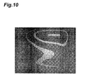
- Fig. 10 is a view showing the intensity distribution in a beam section of light output from a spatial light modulator as another example of the comparative example. This is a result obtained by displaying in the spatial light modulator 30 a pattern for which a blazed grating pattern ⁇ grating , a desired phase pattern ⁇ desire , and a distortion correction pattern ⁇ correction are superimposed, and phase folding is applied by 2 ⁇ .
- a spatial light modulator having a phase modulation amount of 2 ⁇ is used here.
- the desired phase pattern ⁇ desire is with the intention that the intensity distribution in a beam section of light output from the spatial light modulator becomes uniform.
- the black region in the figure is to extend over the whole area entirely.
- a phase pattern (for example, Fig. 8 ) with a phase modulation range of 4 ⁇ or less is presented in the spatial light modulator 30 having a phase modulation range of 4 ⁇ in each pixel. Therefore, light having a desired intensity distribution and phase distribution can be obtained in a beam section, without the necessity for performing phase folding.
- the Laguerre-Gaussian mode beam has an intensity distribution and phase distribution to be specified by a radial index and an azimuthal index in its beam section.
- description will be given of the case where a Laguerre-Gaussian mode beam with a radial index of 1 and an azimuthal index of 3 (hereinafter, described as an "LG 1,3 light") is generated.
- Fig. 11 is a view showing an intensity distribution in a beam section of an LG 1,3 light.
- a blazed grating pattern ⁇ grating is set so that the intensity distribution in a beam section becomes such a distribution as shown in the same figure.
- Fig. 12 is a view showing a blazed grating pattern ⁇ g rating to obtain the intensity distribution ( Fig. 11 ) in a beam section of an LG 1 , 3 light.
- Fig. 13 is a view showing a desired phase pattern ⁇ desire to obtain a phase distribution in a beam section of an LG 1,3 light.
- the phase modulation amount of each pixel is shown by grayscale.
- a phase pattern ⁇ result for generating an LG 1,3 light by the spatial light modulator 30 is a pattern for which the above-described blazed grating pattern ⁇ grating and desired phase pattern ⁇ desire are superimposed, and a distortion correction pattern ⁇ correction is further superimposed thereon.
- a phase pattern ⁇ phase being a sum of the desired phase pattern ⁇ desire and the distortion correction pattern ⁇ correction is applied with phase folding, and has a phase modulation range of 2 ⁇ or less.
- This phase pattern ⁇ result is presented in the spatial light modulator 30.
- phase pattern ⁇ result produced by superimposing a blazed grating pattern ⁇ grating for light diffraction with a phase modulation range of 2 ⁇ or less and a phase pattern ⁇ phase having a predetermined phase modulation distribution with a phase modulation range of 2 ⁇ or less is presented in the spatial light modulator 30 with a phase modulation range of 4 ⁇ , an LG 1,3 light having a desired intensity distribution and phase distribution can be obtained, without the necessity for performing phase folding for the phase pattern ⁇ result .
- Fig. 14 is a view showing an intensity distribution in a beam section of an LG 1 , 3 light generated by the present embodiment.
- Fig. 15 is a view showing an intensity distribution in a beam section of an LG 1 , 3 light generated by the comparative example.
- the LG 1 , 3 light generated by the present embodiment has an intensity distribution close to a desired one in comparison with the LG 1 , 3 light generated by the comparative example.
- a Laguerre-Gaussian mode beam to be thus generated by the light control device 1 according to the present embodiment is close to a desired one in terms of not only the phase distribution but also the intensity distribution in a beam section, and has high mode purity. Therefore, this Laguerre-Gaussian mode beam can be preferably used in optical tweezers or a quantum operation.
- Beam shaping is a technique for converting an input light where the intensity distribution in a beam section is non-uniform to an output light where the intensity distribution in a beam section is as desired.
- Fig. 16 is a chart showing examples of the intensity distribution before beam shaping and the intensity distribution after beam shaping.
- the solid line shows the intensity distribution before beam shaping, while the broken line shows the intensity distribution after beam shaping. It is provided that the closer to the center of the intensity distribution (solid line) before beam shaping, the stronger the intensity, and the intensity distribution (broken line) after beam shaping is uniform.
- a blazed grating pattern ⁇ grating to be used for this beam shaping, the distribution of k-values is set so as to have a diffraction efficiency distribution according to a ratio of the intensity distribution before beam shaping and the intensity distribution after beam shaping in a beam section.
- a phase pattern ⁇ result to be presented in the spatial light modulator 30 is provided as one for which a desired phase pattern ⁇ desire and a distortion correction pattern ⁇ correction are superimposed on this blazed grating pattern ⁇ grating .
- a phase pattern ⁇ phase being a sum of the desired phase pattern ⁇ desire and the distortion correction pattern ⁇ correction is applied with phase folding, and has a phase modulation range of 2 ⁇ or less.
- This phase pattern ⁇ result is presented in the spatial light modulator 30.
- the phase modulation range in this phase pattern ⁇ result is 4 ⁇ or less.
- phase pattern ⁇ result produced by superimposing a blazed grating pattern ⁇ grating for light diffraction with a phase modulation range of 2 ⁇ or less and a phase pattern ⁇ phase having a predetermined phase modulation distribution with a phase modulation range of 2 ⁇ or less is presented in the spatial light modulator 30 with a phase modulation range of 4 ⁇ , a light after beam shaping having a desired intensity distribution and phase distribution can be obtained, without the necessity for performing phase folding for the phase pattern ⁇ result .
- an input light where the intensity distribution in a beam section is non-uniform can be converted to an output light where the intensity distribution in a beam section is as desired.
- beam light with a Gaussian distribution can be shaped into beam light with a uniform distribution called a flat-top beam.
- Such a beam shaping technique is useful for processing applications, illumination for a microscope, and the like.
- the present invention provides a light control device capable of obtaining light having a desired beam section in the technique of causing a phase modulating spatial light modulator to present a phase pattern produced by superimposing a blazed grating pattern and a phase pattern having a predetermined phase modulation distribution.
Abstract
Description
- The present invention relates to a light control device and a light control method.
- Spatial light modulators can modulate the intensity or phase of input light in each of a plurality of two-dimensionally arrayed pixels. Such spatial light modulators include an intensity modulation type spatial light modulator that can modulate only the intensity, a phase modulation type spatial light modulator that can modulate only the phase, and an intensity and phase modulation type spatial light modulator that can modulate both of the intensity and phase. Light output after being modulated in intensity or phase in each pixel of the spatial light modulator, as a result of, for example, being condensed by a condensing optical system provided at a subsequent stage of the spatial light modulator, can process an object existing at its condensing position.
- The intensity modulating spatial light modulator adjusts the transmittance of input light pixel by pixel, and cannot use light of a part that has not been transmitted therethrough, and is thus inferior in light utilization efficiency. It is not easy for the intensity and phase modulating spatial light modulator to control intensity modulation and phase modulation in each pixel independently of each other, and handling thereof is difficult.
- On the other hand, the phase modulating spatial light modulator modulates the phase of input light pixel by pixel, and can output almost entire light, and is thus excellent in light utilization efficiency. Moreover, the phase modulating spatial light modulator, as a result of presenting a phase pattern prepared from a computer-generated hologram or the like, has a high degree of freedom in the phase distribution in a beam section of output light, and has a high degree of freedom in the condensing position of output light by the condensing optical system. As an application of light control using such a phase modulating spatial light modulator, processing of the surface and interior of a processing object, generation of a Laguerre-Gaussian mode beam, and the like can be mentioned.
- Moreover, it has been known that the intensity of outputting light that is phase-modulated pixel by pixel in the phase modulating spatial light modulator can be modulated (refer to Non-Patent Literature 1). This is for causing the phase modulating spatial light modulator to present a phase pattern produced by superimposing a blazed grating pattern for light diffraction and a phase pattern having a predetermined phase modulation distribution, and adjusting the light diffraction efficiency in the spatial light modulator by adjusting the blazed grating pattern. Accordingly, it has been considered that light that is output after being diffracted by the spatial light modulator can have a desired intensity distribution and phase distribution in its beam section.
- Moreover, it has been considered that, generally, since the phase α of a light wave is equivalent to a phase (α+2nπ), it is sufficient that optical phase modulation in each pixel of the spatial light modulator is possible in a range of 2π. Here, n is an arbitrary integer. For example, when the phase modulation amount exceeds 2π, it suffices to add or subtract 2nπ with respect to the phase modulation amount (hereinafter, referred to as "phase folding") to thereby make the phase modulation amount a value within a range from 0 to 2π. It has been considered that, even if the phase modulation amount after phase folding is thus provided as the phase modulation amount of each pixel of the spatial light modulator, no problem arises in principle.
- Conventional spatial light modulators are set so as to have a phase modulation range of 2π. This is because, if the phase modulation range in the spatial light modulator is 2π, a phase modulation exceeding 2π can also be expressed in principle by performing phase folding in the phase pattern. Moreover, this is because a spatial light modulator having a phase modulation range exceeding 2π is not only redundant, but also causes a reduction in resolution and a reduction in response speed in terms of the relationship between the input gradation value and phase modulation amount.
- Non-Patent Literature 1: Joseph P. Kirk and Alan L. Jones, "Phase-only complex-valued spatial filter," Journal of the optical society of America, Vol. 61, No. 8, 1971
- Meanwhile, the present inventor has been engaged in various research and development, taking advantage of being able to cause a phase modulating spatial light modulator to present a phase pattern produced by superimposing a blazed grating pattern and a predetermined phase pattern, and to modulate the intensity of outputting light that is phase-modulated pixel by pixel in this spatial light modulator. The present inventor, in the course of research and development, has discovered that a phenomenon of the intensity distribution and the phase distribution in a beam section of light output from the spatial light modulator different from the desired effect may occur, that is, a phenomenon resulting in degradation in beam quality of light output from the spatial light modulator may occur. Further, the present inventor has discovered that the phenomenon is due to phase folding.
- The present invention has been made in order to solve the above problems, and it is an object of the present invention to provide a light control device and light control method capable of obtaining light having a desired beam section in the technique of causing a phase modulating spatial light modulator to present a phase pattern produced by superimposing a blazed grating pattern and a phase pattern having a predetermined phase modulation distribution.
- A light control device according to the present invention includes (1) a light source that outputs light, (2) a phase modulating spatial light modulator that is capable of phase modulation in each of a plurality of two-dimensionally arrayed pixels in a range of 4π, is input with light output from the light source, presents a phase pattern to modulate the phase of light in each of the pixels, and outputs light after being phase-modulated by this phase pattern, and (3) a control unit that causes the spatial light modulator to present a phase pattern produced by superimposing a blazed grating pattern for light diffraction with a phase modulation range of 2π or less and a phase pattern having a predetermined phase modulation distribution with a phase modulation range of 2π or less, and adjusts the light diffraction efficiency in the spatial light modulator by adjusting the blazed grating pattern.
- In the light control device according to the present invention, it is preferable that the control unit causes the spatial light modulator to present a phase pattern for which the blazed grating pattern having a light diffraction efficiency distribution according to an intensity distribution in a beam section of a Laguerre-Gaussian mode beam with a specific index and the phase pattern having a phase modulation distribution according to a phase distribution in a beam section of the Laguerre-Gaussian mode beam are superimposed.
- Moreover, in the light control device according to the present invention, it is preferable that the control unit causes the spatial light modulator to present a phase pattern for which the blazed grating pattern having a light diffraction efficiency distribution according to an intensity distribution of light having a specific intensity distribution and phase distribution in a beam section and the phase pattern having a phase modulation distribution according to the phase distribution are superimposed.
- A light control method according to the present invention uses (1) a light source that outputs light, and (2) a phase modulating spatial light modulator that is capable of phase modulation in each of a plurality of two-dimensionally arrayed pixels in a range of 4π, is input with light output from the light source, presents a phase pattern to modulate the phase of light in each of the pixels, and outputs light after being phase-modulated by this phase pattern, and (3) causes the spatial light modulator to present a phase pattern produced by superimposing a blazed grating pattern for light diffraction with a phase modulation range of 2π or less and a phase pattern having a predetermined phase modulation distribution with a phase modulation range of 2π or less, and adjusts the light diffraction efficiency in the spatial light modulator by adjusting the blazed grating pattern.
- It is preferable that the light control method according to the present invention causes the spatial light modulator to present a phase pattern for which the blazed grating pattern having a light diffraction efficiency distribution according to an intensity distribution in a beam section of a Laguerre-Gaussian mode beam with a specific index and the phase pattern having a phase modulation distribution according to a phase distribution in a beam section of the Laguerre-Gaussian mode beam are superimposed.
- It is preferable that the light control method according to the present invention causes the spatial light modulator to present a phase pattern for which the blazed grating pattern having a light diffraction efficiency distribution according to an intensity distribution of light having a specific intensity distribution and phase distribution in a beam section and the phase pattern having a phase modulation distribution according to the phase distribution are superimposed.
- According to the present invention, light having a desired beam section can be obtained in the technique of causing a phase modulating spatial light modulator to present a phase pattern produced by superimposing a blazed grating pattern and a phase pattern having a predetermined phase modulation distribution.
-
- [
Fig. 1 ] is a configuration diagram of alight control device 1. - [
Fig. 2 ] is a view showing a blazed grating pattern. - [
Fig. 3 ] is a chart showing an example of the phase modulation distribution in a blazed grating pattern. - [
Fig. 4 ] is a graph showing a relationship between the k-value and diffraction efficiency in a blazed grating pattern presented in an actual spatial light modulator. - [
Fig. 5 ] is a chart showing an example of the phase modulation distribution in a blazed grating pattern. - [
Fig. 6 ] is a table showing an example of the phase modulation amount of each pixel in the blazed grating pattern. - [
Fig. 7 ] is a chart showing an example of the phase modulation distribution in a phase pattern. - [
Fig. 8 ] is a chart showing a phase modulation distribution in a phase pattern where the blazed grating pattern (Fig. 5 andFig. 6 ) and the phase pattern having a predetermined phase modulation distribution (Fig. 7 ) are superimposed. - [
Fig. 9 ] is a chart showing a phase modulation distribution in a phase pattern after performing phase folding for the phase pattern φresult (Fig. 8 ). - [
Fig. 10 ] is a view showing an example of the intensity distribution in a beam section of light output from a spatial light modulator in the case of a comparative example. - [
Fig. 11 ] is a view showing an intensity distribution in a beam section of an LG1,3 light. - [
Fig. 12 ] is a view showing a blazed grating pattern φgrating to obtain the intensity distribution (Fig. 11 ) in a beam section of an LG1,3 light. - [
Fig. 13 ] is a view showing a desired phase pattern φdesire to obtain a phase distribution in a beam section of an LG1,3 light. - [
Fig. 14 ] is a view showing an intensity distribution in a beam section of an LG1,3 light generated by the present embodiment. - [
Fig. 15 ] is a view showing an intensity distribution in a beam section of an LG1,3 light generated by the comparative example. - [
Fig. 16 ] is a chart showing examples of the intensity distribution before beam shaping and the intensity distribution after beam shaping. - 1 ... light control device, 2 ... imaging device, 10 ... light source, 20 ... prism, 30 ... spatial light modulator, 31 ... drive unit, 32 ... control unit, 41 ... lens, 42 ... aperture, 43 ... lens.
- Hereinafter, the best mode for carrying out the present invention will be described in detail with reference to the accompanying drawings. Also, the same components are denoted with the same reference numerals in the description of the drawings, and overlapping description will be omitted.
-
Fig. 1 is a configuration diagram of alight control device 1. Thelight control device 1 shown in this figure includes alight source 10, aprism 20, aspatial light modulator 30, adrive unit 31, acontrol unit 32, alens 41, anaperture 42, and alens 43. Also, in this figure, not only thelight control device 1 but also animaging device 2 is shown. - The phase modulating spatial light modulator to be used in the present invention may be either a reflection type or a transmission type. The reflective spatial light modulator may be any of the LCOS (Liquid Crystal on Silicon) type, the MEMS (Micro Electro Mechanical Systems) type, and the optical address type. Moreover, the transmissive spatial light modulator may be an LCD (Liquid Crystal Display) or the like. In
Fig. 1 , a reflective spatial light modulator is shown as the spatiallight modulator 30. - The
light source 10 is for outputting light that is required to be phase-modulated by the spatiallight modulator 30, is preferably a laser light source, may be a pulsed laser light source such as a femtosecond laser light source and a Nd:YAG laser light source, and may be a CW laser light source such as a He-Ne laser light source. It is preferable that light output from thelight source 10 is collimated by a collimator lens after passing through a spatial filter. - The
prism 20 has a first reflectingsurface 21 and a second reflectingsurface 22. The first reflectingsurface 21 of theprism 20 is input with light output from thelight source 10, and reflects the light toward the spatiallight modulator 30. The second reflectingsurface 22 of theprism 20 is input with light output from the spatiallight modulator 30, and reflects the light toward thelens 41. - The spatial
light modulator 30 is a phase modulating spatial light modulator, includes a plurality of two-dimensionally arrayed pixels, is capable of phase modulation in each of these pixels in a range of 4π, and can present a phase pattern to modulate the phase of light in each of the pixels. The spatiallight modulator 30 is input with light that has reached after being output from thelight source 10 and reflected on the first reflectingsurface 21 of theprism 20, and outputs the light after being phase-modulated by the phase pattern to the second reflectingsurface 22 of theprism 20. Examples of the phase pattern to be presented in the spatiallight modulator 30 that can be mentioned include a CGH (Computer-Generated Hologram) determined by numerical calculation. - The
drive unit 31 is for setting the phase modulation amount in each of the two-dimensionally arrayed pixels of the spatiallight modulator 30, and provides a signal for the pixel-by-pixel setting of the phase modulation amount to the spatiallight modulator 30. Thedrive unit 31 sets the phase modulation amount in each of the two-dimensionally arrayed pixels of the spatiallight modulator 30 to thereby cause the spatiallight modulator 30 to present a phase pattern. - The
control unit 32 is formed of, for example, a computer, and controls operation of thedrive unit 31 to thereby cause a phase pattern to be written into the spatiallight modulator 30 from thedrive unit 31. That is, thecontrol unit 32 stores a phase pattern A that is required to be presented by the spatiallight modulator 30, or prepares that phase pattern A, and causes the phase pattern A to be written into the spatiallight modulator 30 from thedrive unit 31. - This phase pattern A is produced by superimposing a blazed grating pattern for light diffraction with a phase modulation range of 2π or less and a phase pattern having a predetermined phase modulation distribution with a phase modulation range of 2π or less. This phase pattern having a predetermined phase modulation distribution preferably includes a component to realize a desired phase distribution in a light beam section, and also further includes a component to correct a phase distortion of an optical system including the spatial
light modulator 30 in thelight control device 1. The light diffraction efficiency in the spatiallight modulator 30 can be adjusted by adjusting the blazed grating pattern. - The
lens 41 is input with light output from the spatiallight modulator 30 and reflected on the second reflectingsurface 22 of theprism 20. Thelens 41 and thelens 43 form a 4f optical system, and has an opening of theaperture 42 disposed at a focal position therebetween. Theaperture 42 is disposed so that only diffracted light of a desired order passes therethrough. - The
imaging device 2 receives light B output from thelens 43 of thelight control device 1, and obtains an intensity distribution in a beam section of the light B. Theimaging device 2 is for observing the quality of light output from thelight control device 1. Also, in the case of use for processing or the like, a new lens is disposed at a subsequent stage of thelens 43, and a processing object is disposed at its condensing position. - The general operation of the
light control device 1 is as follows. By thedrive unit 31 controlled by thecontrol section 32, a phase pattern produced by superimposing a blazed grating pattern and a phase pattern is presented in the spatiallight modulator 30. The light output from thelight source 10 is reflected on the first reflectingsurface 21 of theprism 20, and input to the spatiallight modulator 30. - The light input to the spatial
light modulator 30 is output after being diffracted by the blazed grating pattern out of the phase pattern presented in the spatiallight modulator 30. The diffraction efficiency at that light diffraction varies depending on the shape of the blazed grating pattern, and may vary depending on the position on a light incident surface of the spatiallight modulator 30. Moreover, the light diffracted and output from the spatiallight modulator 30 has been phase-modulated by the phase pattern having a predetermined phase modulation distribution out of the phase pattern presented in the spatiallight modulator 30. - The light output from the spatial
light modulator 30 is reflected on the second reflectingsurface 22 of theprism 20, passes through thelens 41, theaperture 42, and thelens 43, and received by theimaging device 2 to obtain an intensity distribution in a light beam section. At this time, thelens 41, theaperture 42, and thelens 43 are formed in a configuration to allow diffracted light of a desired diffraction order out of the light output from the spatiallight modulator 30 to selectively pass therethrough. Therefore, the light B to be output to theimaging device 2 from thelens 43 is a light having a desired intensity distribution and phase distribution. - Next, the phase pattern to be presented in the spatial
light modulator 30 will be described in detail. This phase pattern is produced by superimposing a blazed grating pattern for light diffraction and a phase pattern having a predetermined phase modulation distribution.Fig. 2 is a view showing a blazed grating pattern. In this figure, the phase modulation amount (modulation width of 2π) of each pixel is shown by grayscale. When light is input to the spatiallight modulator 30 where such a blazed grating pattern is presented, the light is diffracted. The diffraction efficiency at that light diffraction varies depending on the shape of the blazed grating pattern. - A blazed grating pattern φgrating having N pixels along a specific direction on the light incident surface of the spatial
light modulator 30 as one period is expressed by the following formula (1). Here, n denotes a pixel position within the period along the specific direction. k can take a value not less than 0 and not more than 1. Therefore, the blazed grating pattern φgrating has a phase modulation range of 2kπ, which is 2π or less. -

- The theoretical diffraction efficiency I+1th of this blazed grating pattern φgrating is expressed by the following formula (2), and varies depending on the k-value. Where k takes a value of 1, the theoretical diffraction efficiency I+1th has the maximum value of 1.
-

- Therefore, if the k-values are uneven and distributed in the light incident surface of the spatial
light modulator 30, the light diffraction efficiency in the light incident surface of the spatiallight modulator 30 is also distributed.Fig. 3 is a chart showing an example of the phase modulation distribution in a blazed grating pattern φgrating. In this figure, the horizontal axis indicates the pixel position. As in the example shown in this figure, when the k-value becomes larger as it moves to the right, the diffraction efficiency becomes higher as it moves to the right.Fig. 4 is a graph showing a relationship between the k-value and diffraction efficiency in a blazed grating pattern φgrating presented in an actual spatial light modulator. As shown in this figure, the larger the k-value, the higher the diffraction efficiency. In addition, the angle of diffraction does not depend on the k-value. - A phase pattern φresult to be presented in the spatial
light modulator 30 is a pattern for which the blazed grating pattern φgrating as described above and a desired phase pattern φdesire serving as a phase pattern are superimposed, and is expressed by the following formula (3). Alternatively, a phase pattern φresult to be presented in the spatiallight modulator 30 is produced by superimposing the blazed grating pattern φgrating as described above, a desired phase pattern φdesire serving as a phase pattern, and a distortion correction pattern φcorrection, and expressed by the following formula (4). -

-

- The desired phase pattern φdesire is a pattern to realize a desired phase distribution in a light beam section, and its phase modulation range is 2π or less. Moreover, the distortion correction pattern φcorrection is a pattern to correct a phase distortion of the optical system in the
light control device 1, and the phase modulation range is generally on the order of a few π. The phase distortion of the optical system in thelight control device 1 can exist in the first reflectingsurface 21 and the second reflectingsurface 22 of theprism 20, the spatiallight modulator 30, and thelenses light modulator 30 where such a phase pattern φresult is presented has a desired intensity distribution and phase distribution in its beam section. - In the following, for simplification of description, the above-described formula (3) and formula (4) will be expressed by the following formula (5). A phase pattern φphase in this formula (5) is the desired phase pattern φdesire in the formula (3), or is alternatively a sum of the desired phase pattern φdesire and the distortion correction pattern φcorrection in the formula (4).
-

- Particularly, in the present embodiment, by the following formula (6), phase folding is performed for a phase pattern φphase, and the phase pattern φphase after phase folding is superimposed on the blazed grating pattern φgrating to provide this as the phase pattern φresult to be presented in the spatial
light modulator 30. The phase pattern φphase after phase folding has a phase modulation range of 2π or less. -

- The phase pattern φresult to be presented in the spatial
light modulator 30 has a phase modulation range of 4π or less in the present embodiment. As an example of the blazed grating pattern φgrating included in this phase pattern φresult, one shown inFig. 5 andFig. 6 is considered.Fig. 5 is a chart showing an example of the phase modulation distribution in a blazed grating pattern. In this figure, the horizontal axis indicates the pixel position. Moreover,Fig. 6 is a table showing an example of the phase modulation amount of each pixel in the blazed grating pattern. In this blazed grating pattern φgrating, the k-value is 0.5, the N-value is 8, and the difference in the phase modulation amount between two adjacent pixels is 0.125π. InFig. 5 , the blazed grating pattern φgrating for approximately six periods is shown. - As an example of the phase pattern φphase included in the phase pattern φresult, one shown in
Fig. 7 is considered.Fig. 7 is a chart showing an example of the phase modulation distribution in a phase pattern. In this figure, the horizontal axis indicates the pixel position. This phase pattern φphase, as a result of phase folding of 2π performed according to necessity, includes a part where the phase modulation amount is 0 and a part where the phase modulation amount is 1.25π. -
Fig. 8 is a chart showing a phase modulation distribution in a phase pattern φresult where the blazed grating pattern φgrating (Fig. 5 andFig. 6 ) and the phase pattern φphase (Fig. 7 ) are superimposed. In this figure, the horizontal axis indicates the pixel position. In the phase pattern φresult shown in this figure, the phase modulation amount is 2π or more. -
Fig. 9 is a chart showing a phase modulation distribution in a phase pattern after performing phase folding by 2π for the phase pattern φresult (Fig. 8 ). In this figure as well, the horizontal axis indicates the pixel position. In the phase modulation distribution in the phase pattern (Fig. 9 ) after phase folding, 2π has been subtracted from the phase modulation amounts for pixels with phase modulation amounts exceeding 2π in the phase pattern φresult (Fig. 8 ) before phase folding, and the phase modulation amount in each pixel is in a range from 0 to 2π. - In the case of the present embodiment where the spatial
light modulator 30 having a phase modulation range of 4π is used, the phase pattern (Fig. 8 ) before phase folding (4π or less) is presented in that spatiallight modulator 30. On the other hand, in the case of a comparative example where a spatial light modulator having a phase modulation range of 2π is used, the phase pattern (Fig. 9 ) after phase folding is presented in that spatial light modulator. - The phase pattern (
Fig. 8 ) before phase folding and the phase pattern (Fig. 9 ) after phase folding have mutually equivalent effects in principle. However, in an actual spatial light modulator, a region called a flyback region where the phase is rounded to cause an incorrect display exists in a part where the difference in the phase modulation amount between two adjacent pixels is large. That is, as compared to the phase pattern (Fig. 8 ) before phase folding, in the phase pattern (Fig. 9 ) after phase folding, the flyback regions exist at the positions shown by the arrows in the figure, and accordingly, light having a desired intensity distribution and phase distribution cannot be obtained. - In the case of a comparative example where the phase pattern (
Fig. 9 ) after phase folding is presented in the spatial light modulator having a phase modulation range of 2π, the difference in the phase modulation amount between two adjacent pixels that has been slight before phase folding becomes approximately 2π after phase folding. When an actual spatial light modulator is made to present such a phase pattern after phase folding, in a part where the difference in the phase modulation amount is large between two adjacent pixels in that spatial light modulator, the phase modulation amount cannot completely sharply change, and crosstalk occurs between the two adjacent pixels. Such a part (flyback region) where crosstalk exists is considered to have a particularly remarkable effect when there is a step of approximately 2π in the phase modulation amount between the two adjacent pixels and the flyback region exists within the periodic structure of a blazed grating pattern. - In the case where a change in the phase modulation amount in the phase pattern to be presented in the spatial light modulator is relatively moderate, there are few flyback regions, and the effect that the flyback regions have on the intensity distribution and phase distribution in a beam section of a light output from the spatial light modulator can be mostly disregarded.
-
Fig. 10 is a view showing the intensity distribution in a beam section of light output from a spatial light modulator as another example of the comparative example. This is a result obtained by displaying in the spatial light modulator 30 a pattern for which a blazed grating pattern φgrating, a desired phase pattern φdesire, and a distortion correction pattern φcorrection are superimposed, and phase folding is applied by 2π. A spatial light modulator having a phase modulation amount of 2π is used here. Moreover, the desired phase pattern φdesire is with the intention that the intensity distribution in a beam section of light output from the spatial light modulator becomes uniform. In the intended intensity distribution in a beam section of light, the black region in the figure is to extend over the whole area entirely. However, in the actually obtained intensity distribution in a beam section of light, regions with a strong intensity (white regions in the figure) exist against the intention described above. This is because, besides the blazed grating pattern φgrating having many flyback regions, the phase pattern φresult produced by superimposing thereon the desired phase pattern φdesire and the distortion correction pattern φcorrection has still more flyback regions. - In the comparative example, a part where a failure has been actually found in a beam section of output light is coincident with a place where the phase modulation amount sharply changes in the phase pattern. In an actual spatial light modulator, degradation in the quality of output light becomes a problem that cannot be disregarded. Thus, in the comparative example, light having a desired intensity distribution and phase distribution cannot be obtained due to the effect of flyback regions.
- On the other hand, in the present embodiment, a phase pattern (for example,
Fig. 8 ) with a phase modulation range of 4π or less is presented in the spatiallight modulator 30 having a phase modulation range of 4π in each pixel. Therefore, light having a desired intensity distribution and phase distribution can be obtained in a beam section, without the necessity for performing phase folding. - Next, description will be given of the case where a Laguerre-Gaussian mode beam is generated by use of the
light control device 1 according to the present embodiment. The Laguerre-Gaussian mode beam has an intensity distribution and phase distribution to be specified by a radial index and an azimuthal index in its beam section. In the following, description will be given of the case where a Laguerre-Gaussian mode beam with a radial index of 1 and an azimuthal index of 3 (hereinafter, described as an "LG1,3 light") is generated. -
Fig. 11 is a view showing an intensity distribution in a beam section of an LG1,3 light. A blazed grating pattern φgrating is set so that the intensity distribution in a beam section becomes such a distribution as shown in the same figure.Fig. 12 is a view showing a blazed grating pattern φgrating to obtain the intensity distribution (Fig. 11 ) in a beam section of an LG1,3 light. Moreover,Fig. 13 is a view showing a desired phase pattern φdesire to obtain a phase distribution in a beam section of an LG1,3 light. In each ofFig. 12 andFig. 13 , the phase modulation amount of each pixel is shown by grayscale. - A phase pattern φresult for generating an LG1,3 light by the spatial
light modulator 30 is a pattern for which the above-described blazed grating pattern φgrating and desired phase pattern φdesire are superimposed, and a distortion correction pattern φcorrection is further superimposed thereon. However, a phase pattern φphase being a sum of the desired phase pattern φdesire and the distortion correction pattern φcorrection is applied with phase folding, and has a phase modulation range of 2π or less. This phase pattern φresult is presented in the spatiallight modulator 30. - In the present embodiment, since a phase pattern φresult produced by superimposing a blazed grating pattern φgrating for light diffraction with a phase modulation range of 2π or less and a phase pattern φphase having a predetermined phase modulation distribution with a phase modulation range of 2π or less is presented in the spatial
light modulator 30 with a phase modulation range of 4π, an LG1,3 light having a desired intensity distribution and phase distribution can be obtained, without the necessity for performing phase folding for the phase pattern φresult. On the other hand, in the comparative example, since a spatial light modulator with a phase modulation range of 2π is used, a phase pattern after phase folding is displayed in that spatial light modulator, and therefore, an LG1,3 light having a desired intensity distribution and phase distribution cannot be obtained. -
Fig. 14 is a view showing an intensity distribution in a beam section of an LG1,3 light generated by the present embodiment. Moreover,Fig. 15 is a view showing an intensity distribution in a beam section of an LG1,3 light generated by the comparative example. As can be understood by comparing both, the LG1,3 light generated by the present embodiment has an intensity distribution close to a desired one in comparison with the LG1,3 light generated by the comparative example. - A Laguerre-Gaussian mode beam to be thus generated by the
light control device 1 according to the present embodiment is close to a desired one in terms of not only the phase distribution but also the intensity distribution in a beam section, and has high mode purity. Therefore, this Laguerre-Gaussian mode beam can be preferably used in optical tweezers or a quantum operation. - Next, description will be given of beam shaping using the
light control device 1 according to the present embodiment. Beam shaping is a technique for converting an input light where the intensity distribution in a beam section is non-uniform to an output light where the intensity distribution in a beam section is as desired.Fig. 16 is a chart showing examples of the intensity distribution before beam shaping and the intensity distribution after beam shaping. The solid line shows the intensity distribution before beam shaping, while the broken line shows the intensity distribution after beam shaping. It is provided that the closer to the center of the intensity distribution (solid line) before beam shaping, the stronger the intensity, and the intensity distribution (broken line) after beam shaping is uniform. - For a blazed grating pattern φgrating to be used for this beam shaping, the distribution of k-values is set so as to have a diffraction efficiency distribution according to a ratio of the intensity distribution before beam shaping and the intensity distribution after beam shaping in a beam section. Moreover, a phase pattern φresult to be presented in the spatial
light modulator 30 is provided as one for which a desired phase pattern φdesire and a distortion correction pattern φcorrection are superimposed on this blazed grating pattern φgrating. However, a phase pattern φphase being a sum of the desired phase pattern φdesire and the distortion correction pattern φcorrection is applied with phase folding, and has a phase modulation range of 2π or less. This phase pattern φresult is presented in the spatiallight modulator 30. The phase modulation range in this phase pattern φresult is 4π or less. - In the present embodiment, since a phase pattern φresult produced by superimposing a blazed grating pattern φgrating for light diffraction with a phase modulation range of 2π or less and a phase pattern φphase having a predetermined phase modulation distribution with a phase modulation range of 2π or less is presented in the spatial
light modulator 30 with a phase modulation range of 4π, a light after beam shaping having a desired intensity distribution and phase distribution can be obtained, without the necessity for performing phase folding for the phase pattern φresult. On the other hand, in the comparative example, since a spatial light modulator with a phase modulation range of 2π is used, a phase pattern after phase folding is displayed in that spatial light modulator, and therefore, a light after beam shaping having a desired intensity distribution and phase distribution cannot be obtained. - By thus performing beam shaping by the
light control device 1 according to the present embodiment, an input light where the intensity distribution in a beam section is non-uniform can be converted to an output light where the intensity distribution in a beam section is as desired. For example, beam light with a Gaussian distribution can be shaped into beam light with a uniform distribution called a flat-top beam. Such a beam shaping technique is useful for processing applications, illumination for a microscope, and the like. - The present invention provides a light control device capable of obtaining light having a desired beam section in the technique of causing a phase modulating spatial light modulator to present a phase pattern produced by superimposing a blazed grating pattern and a phase pattern having a predetermined phase modulation distribution.
Claims (6)
- A light control device comprising:a light source that outputs light;a phase modulating spatial light modulator that is capable of phase modulation in each of a plurality of two-dimensionally arrayed pixels in a range of 4π, is input with light output from the light source, presents a phase pattern to modulate the phase of light in each of the pixels, and outputs light after being phase-modulated by this phase pattern; anda control unit that causes the spatial light modulator to present a phase pattern produced by superimposing a blazed grating pattern for light diffraction with a phase modulation range of 2π or less and a phase pattern having a predetermined phase modulation distribution with a phase modulation range of 2π or less, and adjusts the light diffraction efficiency in the spatial light modulator by adjusting the blazed grating pattern.
- The light control device according to claim 1, wherein
the control unit causes the spatial light modulator to present a phase pattern for which the blazed grating pattern having a light diffraction efficiency distribution according to an intensity distribution in a beam section of a Laguerre-Gaussian mode beam with a specific index and the phase pattern having a phase modulation distribution according to a phase distribution in a beam section of the Laguerre-Gaussian mode beam are superimposed. - The light control device according to claim 1, wherein
the control unit causes the spatial light modulator to present a phase pattern for which the blazed grating pattern having a light diffraction efficiency distribution according to an intensity distribution of light having a specific intensity distribution and phase distribution in a beam section and the phase pattern having a phase modulation distribution according to the phase distribution are superimposed. - A light control method using:a light source that outputs light; anda phase modulating spatial light modulator that is capable of phase modulation in each of a plurality of two-dimensionally arrayed pixels in a range of 4π, is input with light output from the light source, presents a phase pattern to modulate the phase of light in each of the pixels, and outputs light after being phase-modulated by this phase pattern,for causing the spatial light modulator to present a phase pattern produced by superimposing a blazed grating pattern for light diffraction with a phase modulation range of 2π or less and a phase pattern having a predetermined phase modulation distribution with a phase modulation range of 2π or less, and adjusting the light diffraction efficiency in the spatial light modulator by adjusting the blazed grating pattern.
- The light control method according to claim 4, for causing the spatial light modulator to present a phase pattern for which the blazed grating pattern having a light diffraction efficiency distribution according to an intensity distribution in a beam section of a Laguerre-Gaussian mode beam with a specific index and the phase pattern having a phase modulation distribution according to a phase distribution in a beam section of the Laguerre-Gaussian mode beam are superimposed.
- The light control method according to claim 4, for causing the spatial light modulator to present a phase pattern for which the blazed grating pattern having a light diffraction efficiency distribution according to an intensity distribution of light having a specific intensity distribution and phase distribution in a beam section and the phase pattern having a phase modulation distribution according to the phase distribution are superimposed.
Applications Claiming Priority (2)
| Application Number | Priority Date | Filing Date | Title |
|---|---|---|---|
| JP2008327855A JP2010151948A (en) | 2008-12-24 | 2008-12-24 | Device and method for controlling light |
| PCT/JP2009/071443 WO2010074149A1 (en) | 2008-12-24 | 2009-12-24 | Light control device and light control method |
Publications (3)
| Publication Number | Publication Date |
|---|---|
| EP2381296A1 true EP2381296A1 (en) | 2011-10-26 |
| EP2381296A4 EP2381296A4 (en) | 2015-05-20 |
| EP2381296B1 EP2381296B1 (en) | 2016-10-05 |
Family
ID=42287756
Family Applications (1)
| Application Number | Title | Priority Date | Filing Date |
|---|---|---|---|
| EP09834947.5A Active EP2381296B1 (en) | 2008-12-24 | 2009-12-24 | Light control device and light control method |
Country Status (7)
| Country | Link |
|---|---|
| US (1) | US8610993B2 (en) |
| EP (1) | EP2381296B1 (en) |
| JP (1) | JP2010151948A (en) |
| KR (1) | KR101605219B1 (en) |
| CN (1) | CN102265207B (en) |
| ES (1) | ES2608466T3 (en) |
| WO (1) | WO2010074149A1 (en) |
Cited By (1)
| Publication number | Priority date | Publication date | Assignee | Title |
|---|---|---|---|---|
| WO2020020782A1 (en) * | 2018-07-23 | 2020-01-30 | Robert Bosch Gmbh | Device for beam shaping for a laser beam used for machining material |
Families Citing this family (8)
| Publication number | Priority date | Publication date | Assignee | Title |
|---|---|---|---|---|
| US8749463B2 (en) * | 2007-01-19 | 2014-06-10 | Hamamatsu Photonics K.K. | Phase-modulating apparatus |
| CN102621609B (en) * | 2012-04-11 | 2014-05-07 | 中国科学院上海光学精密机械研究所 | Etching device and etching method for any apodised fiber bragg grating |
| WO2014077092A1 (en) * | 2012-11-13 | 2014-05-22 | 浜松ホトニクス株式会社 | Light modulation device |
| JP6298050B2 (en) | 2013-06-06 | 2018-03-20 | 浜松ホトニクス株式会社 | Corresponding relationship identification method for adaptive optics system, wavefront distortion compensation method, adaptive optics system, and recording medium for storing adaptive optics system program |
| JP6382033B2 (en) * | 2014-08-29 | 2018-08-29 | 浜松ホトニクス株式会社 | Pulsed light shaping device |
| JP2016055319A (en) * | 2014-09-10 | 2016-04-21 | 浜松ホトニクス株式会社 | Light irradiation device and light irradiation method |
| JP6791088B2 (en) * | 2017-10-11 | 2020-11-25 | 株式会社Jvcケンウッド | Phase modulator |
| US11947104B2 (en) | 2019-09-10 | 2024-04-02 | Korea Basic Science Institute | Reflective spiral phase plate, and apparatus for generating Laguerre Gaussian beam comprising same |
Family Cites Families (14)
| Publication number | Priority date | Publication date | Assignee | Title |
|---|---|---|---|---|
| US5151814A (en) * | 1987-08-19 | 1992-09-29 | Hughes Aircraft Company | Phased array for optical beam control |
| JPH04163529A (en) * | 1990-10-29 | 1992-06-09 | Seiko Epson Corp | Optical phase modulator |
| JP2000010058A (en) * | 1998-06-18 | 2000-01-14 | Hamamatsu Photonics Kk | Spatial light modulating device |
| US6456419B1 (en) * | 2000-09-29 | 2002-09-24 | Innovative Technology Licensing, Llc | Frequency modulated liquid crystal beamsteering device |
| GB0121308D0 (en) * | 2001-09-03 | 2001-10-24 | Thomas Swan & Company Ltd | Optical processing |
| JP4420672B2 (en) * | 2001-10-25 | 2010-02-24 | 浜松ホトニクス株式会社 | Phase modulation apparatus and phase modulation method |
| JP4761432B2 (en) * | 2004-10-13 | 2011-08-31 | 株式会社リコー | Laser processing equipment |
| WO2006072581A1 (en) * | 2005-01-10 | 2006-07-13 | Medizinische Universität Innsbruck | Spiral phase contrast imaging in microscopy |
| US7283291B2 (en) * | 2005-04-08 | 2007-10-16 | The Boeing Company | High speed beam steering/field of view adjustment |
| US7633671B2 (en) * | 2005-04-08 | 2009-12-15 | The Boeing Company | High speed beam steering |
| JP4947639B2 (en) * | 2007-01-19 | 2012-06-06 | 浜松ホトニクス株式会社 | Reflection type phase change device and setting method of reflection type phase modulation device |
| US8749463B2 (en) * | 2007-01-19 | 2014-06-10 | Hamamatsu Photonics K.K. | Phase-modulating apparatus |
| JP5622571B2 (en) * | 2007-07-20 | 2014-11-12 | メディツィーニシェ・ウニヴェルジテート・インスブルックMedizinische Universitaet Innsbruck | Optical device comprising a pair of diffractive optical elements |
| GB2454246B (en) * | 2007-11-02 | 2010-03-10 | Light Blue Optics Ltd | Holographic image display systems |
-
2008
- 2008-12-24 JP JP2008327855A patent/JP2010151948A/en active Pending
-
2009
- 2009-12-24 WO PCT/JP2009/071443 patent/WO2010074149A1/en active Application Filing
- 2009-12-24 EP EP09834947.5A patent/EP2381296B1/en active Active
- 2009-12-24 CN CN200980152729.8A patent/CN102265207B/en active Active
- 2009-12-24 US US13/141,556 patent/US8610993B2/en active Active
- 2009-12-24 KR KR1020117015531A patent/KR101605219B1/en active IP Right Grant
- 2009-12-24 ES ES09834947.5T patent/ES2608466T3/en active Active
Non-Patent Citations (1)
| Title |
|---|
| See references of WO2010074149A1 * |
Cited By (1)
| Publication number | Priority date | Publication date | Assignee | Title |
|---|---|---|---|---|
| WO2020020782A1 (en) * | 2018-07-23 | 2020-01-30 | Robert Bosch Gmbh | Device for beam shaping for a laser beam used for machining material |
Also Published As
| Publication number | Publication date |
|---|---|
| EP2381296A4 (en) | 2015-05-20 |
| ES2608466T3 (en) | 2017-04-11 |
| EP2381296B1 (en) | 2016-10-05 |
| WO2010074149A1 (en) | 2010-07-01 |
| CN102265207A (en) | 2011-11-30 |
| US8610993B2 (en) | 2013-12-17 |
| CN102265207B (en) | 2014-03-26 |
| JP2010151948A (en) | 2010-07-08 |
| US20110317237A1 (en) | 2011-12-29 |
| KR20110096150A (en) | 2011-08-29 |
| KR101605219B1 (en) | 2016-03-21 |
Similar Documents
| Publication | Publication Date | Title |
|---|---|---|
| EP2381296B1 (en) | Light control device and light control method | |
| US9001411B2 (en) | Light control device and light control method | |
| US9488831B2 (en) | Aberration-correcting method, laser processing method using said aberration-correcting method, laser irradiation method using said aberration-correcting method, aberration-correcting device and aberration-correcting program | |
| US20210011300A1 (en) | Display device | |
| EP2888575B1 (en) | Stimulated emission depletion microscopy | |
| US10067401B2 (en) | Beam expander | |
| US8867113B2 (en) | Laser processing device and laser processing method | |
| US9442295B2 (en) | Beam-shaping device | |
| KR20150072151A (en) | Hologram printing apparatus and method for recording of holographic elements images using spatial light modulator | |
| EP3193207B1 (en) | Light irradiating device and light irradiating method | |
| WO2016087393A1 (en) | Multi-wavelength generalized phase contrast system and method | |
| CN105122116A (en) | Optical module and observation device | |
| JP2010058128A (en) | Laser beam irradiation apparatus and laser beam irradiation method | |
| Hoffmann et al. | Kilohertz binary phase modulator for pulsed laser sources using a digital micromirror device | |
| Steiger et al. | SLM-based off-axis Fourier filtering in microscopy with white light illumination | |
| US9798165B2 (en) | Light modulation device | |
| Bouchal et al. | Achromatic correction of diffractive dispersion in white light SLM imaging | |
| Matsumoto et al. | Modulation of the pupil function of microscope objective lens for multifocal multi-photon microscopy using a spatial light modulator |
Legal Events
| Date | Code | Title | Description |
|---|---|---|---|
| PUAI | Public reference made under article 153(3) epc to a published international application that has entered the european phase |
Free format text: ORIGINAL CODE: 0009012 |
|
| 17P | Request for examination filed |
Effective date: 20110720 |
|
| AK | Designated contracting states |
Kind code of ref document: A1 Designated state(s): AT BE BG CH CY CZ DE DK EE ES FI FR GB GR HR HU IE IS IT LI LT LU LV MC MK MT NL NO PL PT RO SE SI SK SM TR |
|
| DAX | Request for extension of the european patent (deleted) | ||
| RA4 | Supplementary search report drawn up and despatched (corrected) |
Effective date: 20150421 |
|
| RIC1 | Information provided on ipc code assigned before grant |
Ipc: G02B 26/08 20060101ALI20150415BHEP Ipc: G02B 21/08 20060101ALI20150415BHEP Ipc: G02B 26/06 20060101ALI20150415BHEP Ipc: G02B 27/09 20060101ALI20150415BHEP Ipc: G02B 27/42 20060101ALI20150415BHEP Ipc: G02F 1/01 20060101AFI20150415BHEP |
|
| REG | Reference to a national code |
Ref country code: DE Ref legal event code: R079 Ref document number: 602009041607 Country of ref document: DE Free format text: PREVIOUS MAIN CLASS: G02F0001010000 Ipc: G03H0001080000 |
|
| GRAP | Despatch of communication of intention to grant a patent |
Free format text: ORIGINAL CODE: EPIDOSNIGR1 |
|
| INTG | Intention to grant announced |
Effective date: 20160609 |
|
| RIC1 | Information provided on ipc code assigned before grant |
Ipc: G02B 26/06 20060101ALI20160527BHEP Ipc: G02B 21/08 20060101ALI20160527BHEP Ipc: G02B 27/42 20060101ALI20160527BHEP Ipc: G03H 1/08 20060101AFI20160527BHEP Ipc: G02B 26/08 20060101ALI20160527BHEP |
|
| GRAS | Grant fee paid |
Free format text: ORIGINAL CODE: EPIDOSNIGR3 |
|
| GRAA | (expected) grant |
Free format text: ORIGINAL CODE: 0009210 |
|
| AK | Designated contracting states |
Kind code of ref document: B1 Designated state(s): AT BE BG CH CY CZ DE DK EE ES FI FR GB GR HR HU IE IS IT LI LT LU LV MC MK MT NL NO PL PT RO SE SI SK SM TR |
|
| REG | Reference to a national code |
Ref country code: GB Ref legal event code: FG4D |
|
| REG | Reference to a national code |
Ref country code: CH Ref legal event code: EP |
|
| REG | Reference to a national code |
Ref country code: AT Ref legal event code: REF Ref document number: 835131 Country of ref document: AT Kind code of ref document: T Effective date: 20161015 |
|
| REG | Reference to a national code |
Ref country code: IE Ref legal event code: FG4D |
|
| REG | Reference to a national code |
Ref country code: FR Ref legal event code: PLFP Year of fee payment: 8 |
|
| REG | Reference to a national code |
Ref country code: DE Ref legal event code: R096 Ref document number: 602009041607 Country of ref document: DE |
|
| REG | Reference to a national code |
Ref country code: NL Ref legal event code: MP Effective date: 20161005 |
|
| REG | Reference to a national code |
Ref country code: LT Ref legal event code: MG4D |
|
| PG25 | Lapsed in a contracting state [announced via postgrant information from national office to epo] |
Ref country code: LV Free format text: LAPSE BECAUSE OF FAILURE TO SUBMIT A TRANSLATION OF THE DESCRIPTION OR TO PAY THE FEE WITHIN THE PRESCRIBED TIME-LIMIT Effective date: 20161005 |
|
| REG | Reference to a national code |
Ref country code: AT Ref legal event code: MK05 Ref document number: 835131 Country of ref document: AT Kind code of ref document: T Effective date: 20161005 |
|
| REG | Reference to a national code |
Ref country code: ES Ref legal event code: FG2A Ref document number: 2608466 Country of ref document: ES Kind code of ref document: T3 Effective date: 20170411 |
|
| PG25 | Lapsed in a contracting state [announced via postgrant information from national office to epo] |
Ref country code: NO Free format text: LAPSE BECAUSE OF FAILURE TO SUBMIT A TRANSLATION OF THE DESCRIPTION OR TO PAY THE FEE WITHIN THE PRESCRIBED TIME-LIMIT Effective date: 20170105 Ref country code: LT Free format text: LAPSE BECAUSE OF FAILURE TO SUBMIT A TRANSLATION OF THE DESCRIPTION OR TO PAY THE FEE WITHIN THE PRESCRIBED TIME-LIMIT Effective date: 20161005 Ref country code: SE Free format text: LAPSE BECAUSE OF FAILURE TO SUBMIT A TRANSLATION OF THE DESCRIPTION OR TO PAY THE FEE WITHIN THE PRESCRIBED TIME-LIMIT Effective date: 20161005 Ref country code: GR Free format text: LAPSE BECAUSE OF FAILURE TO SUBMIT A TRANSLATION OF THE DESCRIPTION OR TO PAY THE FEE WITHIN THE PRESCRIBED TIME-LIMIT Effective date: 20170106 |
|
| PG25 | Lapsed in a contracting state [announced via postgrant information from national office to epo] |
Ref country code: AT Free format text: LAPSE BECAUSE OF FAILURE TO SUBMIT A TRANSLATION OF THE DESCRIPTION OR TO PAY THE FEE WITHIN THE PRESCRIBED TIME-LIMIT Effective date: 20161005 Ref country code: BE Free format text: LAPSE BECAUSE OF FAILURE TO SUBMIT A TRANSLATION OF THE DESCRIPTION OR TO PAY THE FEE WITHIN THE PRESCRIBED TIME-LIMIT Effective date: 20161005 Ref country code: HR Free format text: LAPSE BECAUSE OF FAILURE TO SUBMIT A TRANSLATION OF THE DESCRIPTION OR TO PAY THE FEE WITHIN THE PRESCRIBED TIME-LIMIT Effective date: 20161005 Ref country code: PL Free format text: LAPSE BECAUSE OF FAILURE TO SUBMIT A TRANSLATION OF THE DESCRIPTION OR TO PAY THE FEE WITHIN THE PRESCRIBED TIME-LIMIT Effective date: 20161005 Ref country code: NL Free format text: LAPSE BECAUSE OF FAILURE TO SUBMIT A TRANSLATION OF THE DESCRIPTION OR TO PAY THE FEE WITHIN THE PRESCRIBED TIME-LIMIT Effective date: 20161005 Ref country code: PT Free format text: LAPSE BECAUSE OF FAILURE TO SUBMIT A TRANSLATION OF THE DESCRIPTION OR TO PAY THE FEE WITHIN THE PRESCRIBED TIME-LIMIT Effective date: 20170206 Ref country code: FI Free format text: LAPSE BECAUSE OF FAILURE TO SUBMIT A TRANSLATION OF THE DESCRIPTION OR TO PAY THE FEE WITHIN THE PRESCRIBED TIME-LIMIT Effective date: 20161005 Ref country code: IS Free format text: LAPSE BECAUSE OF FAILURE TO SUBMIT A TRANSLATION OF THE DESCRIPTION OR TO PAY THE FEE WITHIN THE PRESCRIBED TIME-LIMIT Effective date: 20170205 |
|
| REG | Reference to a national code |
Ref country code: DE Ref legal event code: R097 Ref document number: 602009041607 Country of ref document: DE |
|
| PG25 | Lapsed in a contracting state [announced via postgrant information from national office to epo] |
Ref country code: DK Free format text: LAPSE BECAUSE OF FAILURE TO SUBMIT A TRANSLATION OF THE DESCRIPTION OR TO PAY THE FEE WITHIN THE PRESCRIBED TIME-LIMIT Effective date: 20161005 Ref country code: EE Free format text: LAPSE BECAUSE OF FAILURE TO SUBMIT A TRANSLATION OF THE DESCRIPTION OR TO PAY THE FEE WITHIN THE PRESCRIBED TIME-LIMIT Effective date: 20161005 Ref country code: RO Free format text: LAPSE BECAUSE OF FAILURE TO SUBMIT A TRANSLATION OF THE DESCRIPTION OR TO PAY THE FEE WITHIN THE PRESCRIBED TIME-LIMIT Effective date: 20161005 Ref country code: SK Free format text: LAPSE BECAUSE OF FAILURE TO SUBMIT A TRANSLATION OF THE DESCRIPTION OR TO PAY THE FEE WITHIN THE PRESCRIBED TIME-LIMIT Effective date: 20161005 Ref country code: CZ Free format text: LAPSE BECAUSE OF FAILURE TO SUBMIT A TRANSLATION OF THE DESCRIPTION OR TO PAY THE FEE WITHIN THE PRESCRIBED TIME-LIMIT Effective date: 20161005 |
|
| REG | Reference to a national code |
Ref country code: CH Ref legal event code: PL |
|
| PLBE | No opposition filed within time limit |
Free format text: ORIGINAL CODE: 0009261 |
|
| STAA | Information on the status of an ep patent application or granted ep patent |
Free format text: STATUS: NO OPPOSITION FILED WITHIN TIME LIMIT |
|
| PG25 | Lapsed in a contracting state [announced via postgrant information from national office to epo] |
Ref country code: BG Free format text: LAPSE BECAUSE OF FAILURE TO SUBMIT A TRANSLATION OF THE DESCRIPTION OR TO PAY THE FEE WITHIN THE PRESCRIBED TIME-LIMIT Effective date: 20170105 Ref country code: SM Free format text: LAPSE BECAUSE OF FAILURE TO SUBMIT A TRANSLATION OF THE DESCRIPTION OR TO PAY THE FEE WITHIN THE PRESCRIBED TIME-LIMIT Effective date: 20161005 Ref country code: IT Free format text: LAPSE BECAUSE OF FAILURE TO SUBMIT A TRANSLATION OF THE DESCRIPTION OR TO PAY THE FEE WITHIN THE PRESCRIBED TIME-LIMIT Effective date: 20161005 |
|
| 26N | No opposition filed |
Effective date: 20170706 |
|
| PG25 | Lapsed in a contracting state [announced via postgrant information from national office to epo] |
Ref country code: MC Free format text: LAPSE BECAUSE OF FAILURE TO SUBMIT A TRANSLATION OF THE DESCRIPTION OR TO PAY THE FEE WITHIN THE PRESCRIBED TIME-LIMIT Effective date: 20161005 |
|
| REG | Reference to a national code |
Ref country code: IE Ref legal event code: MM4A |
|
| PG25 | Lapsed in a contracting state [announced via postgrant information from national office to epo] |
Ref country code: LI Free format text: LAPSE BECAUSE OF NON-PAYMENT OF DUE FEES Effective date: 20161231 Ref country code: LU Free format text: LAPSE BECAUSE OF NON-PAYMENT OF DUE FEES Effective date: 20161224 Ref country code: CH Free format text: LAPSE BECAUSE OF NON-PAYMENT OF DUE FEES Effective date: 20161231 |
|
| REG | Reference to a national code |
Ref country code: FR Ref legal event code: PLFP Year of fee payment: 9 |
|
| PG25 | Lapsed in a contracting state [announced via postgrant information from national office to epo] |
Ref country code: IE Free format text: LAPSE BECAUSE OF NON-PAYMENT OF DUE FEES Effective date: 20161224 Ref country code: SI Free format text: LAPSE BECAUSE OF FAILURE TO SUBMIT A TRANSLATION OF THE DESCRIPTION OR TO PAY THE FEE WITHIN THE PRESCRIBED TIME-LIMIT Effective date: 20161005 |
|
| PG25 | Lapsed in a contracting state [announced via postgrant information from national office to epo] |
Ref country code: HU Free format text: LAPSE BECAUSE OF FAILURE TO SUBMIT A TRANSLATION OF THE DESCRIPTION OR TO PAY THE FEE WITHIN THE PRESCRIBED TIME-LIMIT; INVALID AB INITIO Effective date: 20091224 Ref country code: CY Free format text: LAPSE BECAUSE OF FAILURE TO SUBMIT A TRANSLATION OF THE DESCRIPTION OR TO PAY THE FEE WITHIN THE PRESCRIBED TIME-LIMIT Effective date: 20161005 |
|
| PG25 | Lapsed in a contracting state [announced via postgrant information from national office to epo] |
Ref country code: TR Free format text: LAPSE BECAUSE OF FAILURE TO SUBMIT A TRANSLATION OF THE DESCRIPTION OR TO PAY THE FEE WITHIN THE PRESCRIBED TIME-LIMIT Effective date: 20161005 Ref country code: MK Free format text: LAPSE BECAUSE OF FAILURE TO SUBMIT A TRANSLATION OF THE DESCRIPTION OR TO PAY THE FEE WITHIN THE PRESCRIBED TIME-LIMIT Effective date: 20161005 |
|
| PG25 | Lapsed in a contracting state [announced via postgrant information from national office to epo] |
Ref country code: MT Free format text: LAPSE BECAUSE OF NON-PAYMENT OF DUE FEES Effective date: 20161224 |
|
| PGFP | Annual fee paid to national office [announced via postgrant information from national office to epo] |
Ref country code: ES Payment date: 20230109 Year of fee payment: 14 |
|
| P01 | Opt-out of the competence of the unified patent court (upc) registered |
Effective date: 20230517 |
|
| PGFP | Annual fee paid to national office [announced via postgrant information from national office to epo] |
Ref country code: GB Payment date: 20231102 Year of fee payment: 15 |
|
| PGFP | Annual fee paid to national office [announced via postgrant information from national office to epo] |
Ref country code: FR Payment date: 20231108 Year of fee payment: 15 Ref country code: DE Payment date: 20231031 Year of fee payment: 15 |
|
| PGFP | Annual fee paid to national office [announced via postgrant information from national office to epo] |
Ref country code: ES Payment date: 20240110 Year of fee payment: 15 |