EP2381286A2 - Système optique à grand champ de vision et procédé d'imagerie du sol - Google Patents
Système optique à grand champ de vision et procédé d'imagerie du sol Download PDFInfo
- Publication number
- EP2381286A2 EP2381286A2 EP11151597A EP11151597A EP2381286A2 EP 2381286 A2 EP2381286 A2 EP 2381286A2 EP 11151597 A EP11151597 A EP 11151597A EP 11151597 A EP11151597 A EP 11151597A EP 2381286 A2 EP2381286 A2 EP 2381286A2
- Authority
- EP
- European Patent Office
- Prior art keywords
- optical system
- fov
- optical
- mirror
- power
- Prior art date
- Legal status (The legal status is an assumption and is not a legal conclusion. Google has not performed a legal analysis and makes no representation as to the accuracy of the status listed.)
- Granted
Links
- 230000003287 optical effect Effects 0.000 title claims abstract description 141
- 238000003384 imaging method Methods 0.000 title claims description 17
- 238000000034 method Methods 0.000 title claims description 11
- 210000001747 pupil Anatomy 0.000 description 6
- 230000007423 decrease Effects 0.000 description 4
- 230000000694 effects Effects 0.000 description 4
- 241000226585 Antennaria plantaginifolia Species 0.000 description 3
- 230000009286 beneficial effect Effects 0.000 description 2
- 230000008901 benefit Effects 0.000 description 2
- 230000008859 change Effects 0.000 description 2
- 238000000701 chemical imaging Methods 0.000 description 2
- 230000006835 compression Effects 0.000 description 1
- 238000007906 compression Methods 0.000 description 1
- 230000001627 detrimental effect Effects 0.000 description 1
- 230000005670 electromagnetic radiation Effects 0.000 description 1
- 230000006872 improvement Effects 0.000 description 1
- 238000004519 manufacturing process Methods 0.000 description 1
- 238000012986 modification Methods 0.000 description 1
- 230000004048 modification Effects 0.000 description 1
- 230000001681 protective effect Effects 0.000 description 1
- 238000001228 spectrum Methods 0.000 description 1
Images


Classifications
-
- G—PHYSICS
- G02—OPTICS
- G02B—OPTICAL ELEMENTS, SYSTEMS OR APPARATUS
- G02B17/00—Systems with reflecting surfaces, with or without refracting elements
- G02B17/02—Catoptric systems, e.g. image erecting and reversing system
- G02B17/06—Catoptric systems, e.g. image erecting and reversing system using mirrors only, i.e. having only one curved mirror
- G02B17/0647—Catoptric systems, e.g. image erecting and reversing system using mirrors only, i.e. having only one curved mirror using more than three curved mirrors
- G02B17/0657—Catoptric systems, e.g. image erecting and reversing system using mirrors only, i.e. having only one curved mirror using more than three curved mirrors off-axis or unobscured systems in which all of the mirrors share a common axis of rotational symmetry
Definitions
- the present invention relates to a wide-field-of-view optical system and a method for imaging the ground.
- this application generally relates to optical systems, and more particularly to an all-reflective wide-field-of-view telescope with beneficial distortion correction.
- WFOV optical systems are of the inverse-telephoto family. This generally means that there is considerable negative optical power in the optical elements at the front of the optical system and considerable positive optical power in the optical elements at the rear of the optical system. In contrast to this, the family of telephoto optical forms has considerable positive optical power in front and considerable negative optical power at the rear. Examples of inverse- telephoto optical system are described, for instance, in U.S. Patent Application Publication No. 2008/0266687 , herein incorporated by reference in its entirety. These optical systems may be characterized, for example, as having a large negative powered first optical element, or the so-called "fish-eye" configuration.
- these systems have noticeable negative (or barrel) distortion, i.e., where the focal length at the edge of the field of view (FOV) is shorter than at the FOV center. This gives rise to image compression at the FOV edge.
- FOV field of view
- the shorter focal length at the FOV edge combines with the longer range at the FOV edges to greatly increase the ground sample distance (GSD). This is generally detrimental to the spatial resolution of optical systems at the FOV edges.
- a wide field of view (WFOV) optical system comprises: a negative optical-power primary mirror configured to receive and reflect light from an image scene; a low optical-power secondary mirror configured to receive and reflect light from the primary mirror; a negative optical-power tertiary mirror configured to receive and reflect light from the secondary mirror; and a positive optical-power quaternary mirror configured to receive and reflect light from the tertiary mirror, wherein the primary, secondary, tertiary and quaternary mirrors are configured to maintain an effective focal length (EFL) at edges of the field of view (FOV) of the optical system to be at least equal to that at the center of the FOV of the optical system so that a spatial resolution of the optical system essentially remains constant across the FOV.
- ETL effective focal length
- an aperture stop is located between the quaternary mirror and the image plane.
- the FOV of the optical system is configured to be approximately 60 degrees.
- the FOV of the optical system is configured to be approximately 120 degrees.
- the EFL at the edges of the FOV is greater than the EFL at the center of the FOV.
- the mirrors provide positive distortion at one of the edges of the FOV of about +15% or more.
- the mirrors provide positive distortion at one of the edges of the FOV of about +100% or more.
- the EFL at the edges of the FOV is essentially the same as the EFL at the center of the FOV.
- the optical system further comprises an imaging device located at the image plane of the optical system.
- the imaging device comprises a spectrometer.
- the optical system further comprises a housing for at least partially integrating and containing the mirrors.
- a method for imaging the ground from an altitude comprises: providing a wide field of view (WFOV) optical system including: a negative optical-power primary mirror configured to receive and reflect light from an image scene and reflect; a low optical-power secondary mirror configured to receive and reflect light from the primary mirror; a negative optical-power tertiary mirror configured to receive and reflect light from the secondary mirror; and a positive optical-power quaternary mirror configured to receive and reflect light from the tertiary mirror; and configuring the primary, secondary, tertiary and quaternary mirrors so as to maintain an effective focal length (EFL) at edges of a field of view (FOV) of the optical system to be at least equal to that at the center of the FOV of the optical system so that a spatial resolution of the optical system essentially remains constant across the FOV.
- ETL effective focal length
- the method further comprises positioning an aperture stop between the quaternary mirror and the image plane.
- the FOV of the optical system is configured to be approximately 60 degrees.
- the FOV of the optical system is configured to be approximately 120 degrees.
- the EFL at the edges of the FOV is greater than the EFL at the center of the FOV.
- the mirrors provide positive distortion at one of the edges of the FOV of about +15% or more.
- the mirrors provide positive distortion at one of the edges of the FOV of about +100% or more.
- the EFL at the edges of the FOV is about the same as the EFL at the center of the FOV.
- the method further comprises positioning an imaging device at the image plane of the optical system.
- the imaging device comprises a spectrometer.
- the method further comprises providing a housing for at least partially integrating and containing the mirrors.
- a WFOV reflective optical system which increases the FOV, while maintaining an effective focal length (EFL) at edges of the field of view (FOV) of the optical system to be at least equal to that at the center of the FOV of the optical system so as that the spatial resolution of the optical system does not degrade across the FOV (i.e., it essentially remains constant).
- EFL effective focal length
- positive distortion may be introduced wherein the EFL at an edge of the FOV is substantially greater than that at the center for the FOV.
- Figure 1 (a) illustrates scenario 100 depicting the viewing angle of a WFOV optical system 5 positioned above the ground and looking downward.
- a "wide field of view (WFOV) optical system” may be characterized as having a total FOV of 60 degrees or greater.
- WFOV optical system 5 may be mounted on a satellite, space station, rocket, airplane, helicopter, balloon, blimp, dirigible, cruise missile, autonomous drone aircraft, or other air- or space-based platforms. It may be may be configured to image ground 10 and/or ground-based objects. Different points A-E on ground 10 are depicted corresponding to different FOVs of optical system 5.
- the distance from optical system 5 to ground 10 at point C along the nadir is depicted as Rn.
- Rn The distance from optical system 5 to ground 10 at point C along the nadir (i.e., looking straight down to the ground from object 5) is depicted as Rn.
- the viewing distance from optical system 5 to points B and D on ground 10 is approximately 1.15 x Rn.
- the viewing distance from optical system 5 to points A and E on ground 10 is 2 x Rn.
- scenario 100 assumes a "flat-Earth" model.
- the flat-Earth model there is a 2:1 ratio of the viewing distance to nadir Rn at a FOV of 120 degrees.
- This flat-Earth assumption may be generally accurate for an altitude up to about 60,000 feet. Above that altitude, the flat-Earth model may no longer be suitable.
- LEO low Earth orbit
- Figures 1(b)-1(d) show the effects of different distortions on the FOV. While the FOV is shown as being square in these examples, it will be appreciated that the FOV may be circular or differently-shaped based on the optics of the particular optical system.
- Figure 1(b) shows image 50 of a 6 x 6 grid in FOV having no distortion. There is no noticeable change in the image shape at center O of the FOV compared to at the boundary edges of FOV.
- Figure 1(c) shows image 50' of the 6 x 6 grid shown in Figure 1(b) having negative distortion (i.e., where the EFL decreases with distance from the center of the FOV).
- This distortion causes a so-called “barrel” effect on the image making it appear to recede radially inwardly from center O of FOV; this is particularly evident at the FOV diagonal. By doing so, some spatial resolution at the boundary edges of FOV has been lost.
- Figure 1(d) shows image 50" of the 6 x 6 grid shown in Figure 1(b) having positive distortion (i.e., where the EFL increases with distance from the center of the FOV).
- the distortion causes a so-called "pincushion" effect in which the boundary edges of FOV of the image appear protruding outwardly to center O of FOV; this is particularly evident at the FOV diagonal.
- the spatial resolution at the edges of FOV has not been lost and may actually improve.
- Electronic distortion correction algorithms may be used to correct for negative and/or positive distortion as known in the art. These algorithms generally change the shape of the image collected. However, the lost spatial resolution at the edges of the FOV due to negative distortion cannot be regained and/or corrected by electronic distortion correction algorithms alone.
- Figures 2(a) and (b) depict a ray-trace section of WFOV optical system 200 in accordance with an embodiment.
- Figure 2(a) shows a side view
- Figure 2(b) shows a top view of optical system 200.
- Optical system 200 may be configured in some implementations as a wide angle large reflective unobscured systems (WALRUS)-type optical systems characterized as having significant negative optical power in the front mirror or mirrors (e.g., the primary, the primary and secondary or even the primary, secondary and tertiary) and significant positive optical power in the rear mirror or mirrors (e.g., the quaternary or possibly the tertiary and quaternary) and an external posterior aperture stop. As shown, optical system 200 may be configured provide a 60 degree line FOV.
- WALRUS wide angle large reflective unobscured systems
- Optical system 200 may include four optically powered mirrors.
- an "optically powered mirror” has a positive or negative optical power rather than zero optical power. Mirrors with positive or negative optical power are curved, while mirrors with zero optical power are substantially flat.
- negative optical-power primary mirror 210 low optical-power secondary mirror 220, negative optical-power tertiary mirror 230, and positive optical-power quaternary mirror 240 closest (as measured along the beam path) to image plane 260.
- Light from scene S is incident on primary mirror 210, reflects from the primary mirror 210 to secondary mirror 220, reflects from secondary mirror 220 to tertiary mirror 230, reflects from tertiary mirror 230 to quaternary mirror 240, and reflects from quaternary mirror 240 through aperture stop 250 to image plane 260.
- aperture stop 250 may be located essentially midway between the quaternary mirror 240 and image plane 260.
- Secondary mirror 220 is low optical-powered in that it has a much longer radius that than the other mirrors.
- the radius of secondary mirror 220 may be at least 10 times that of the radii of the other mirrors.
- the location of image plane 260 may be used for positioning an imaging device.
- a reflective double-pass spectrometer for hyperspectral imaging applications may be used, as described, for example, in U.S. Patent Application Publication No. 2008/0266687 , mentioned above.
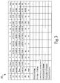
- Figure 3 shows one optical prescription 300 for an exemplary implementation of WFOV optical system 200 in accordance with an embodiment, and which is raytraced forward.
- Ad, Ae, Af, Ag are aspheric constants
- CC is a conic constant
- Yd is a decenter in the y direction
- Alpha is a tilt in the y direction meaning a rotational axis that runs parallel to the x axis.
- the configuration enables optical system 200 to have a 60 degree FOV, and positive distortion of about +15% or more.
- the positive sign distortion means that the focal length at the FOV edge is longer than that at the FOV center.
- Positive distortion (rather than negative distortion) is beneficial in this situation in that no spatial resolution of the image may be lost at the edges of the FOV.
- the ground sample distance (GSD) may remain constant.
- this positive distortion substantially counteracts the increased range at the edge of a +/- 30 deg. FOV, so that the GSD remains nearly constant across the FOV.
- the ground sample distance is maintained, and the spatial resolution of the optical system does not degrade across the FOV.
- optical system 200 may advantageously provide benefits for airborne and space-borne sensing systems, alike, including pan and hyperspectal imaging.
- Figure 4 is a plot of effective focal length (EFL) vs. the off-nadir view angle for a conventional inverse- telephoto optical system and WFOV optical system 200, respectively.
- the conventionally-depicted inverse- telephoto optical system might be configured consistent with the disclosure in U.S. Patent Application Publication No. 2008/0266687 , mentioned above.
- the plots shows distortion in the along-scan (A-S) direction and the cross-scan (C-S) direction.
- A-S direction generally corresponds to the view looking toward the ground parallel to the direction in which an optical system may be moving (e.g., in a trajectory, flight path, orbit, etc.).
- C-S generally direction corresponds to the view looking toward the ground orthogonal to the A-S direction.
- the EFL for the conventional optical system in both C-S and A-S directions significantly decreases. This may correspond to negative (or barrel) distortion of about -17% or more.
- the EFL for optical system 200 significantly increases in the C-S direction.
- the EFL in the A-S direction generally follows the trend of the C-S focal length and increases toward the FOV edge (although not as much). This may correspond to a positive (or pincushion) distortion of about +15% or more. Additionally, there is considerable less anamorphism with the A-S focal length average being about the same as the C-S focal length average. This permits optical system 200 to more closely track targets at both the center and at the edges of the field of view than the conventional optical system.
- Figures 5(a) and (b) depict a ray-trace section of WFOV optical system 500 in accordance with an embodiment.
- Figure 5(a) shows a side view
- Figure 5(b) shows a top view of optical system 500.
- Optical system 500 may be configured as a unobscured WALRUS-type optical system, and may be, in some instances, characterized as having significant negative optical power in the front mirror or mirrors and significant positive optical power in the rear mirror or mirrors and having an external posterior aperture stop. As shown, optical system 500 may be configured to provide a 120 degree FOV.
- Optical system 500 includes four optically powered mirrors. As depicted on the beam path beginning from image scene S, there is negative optical-power primary mirror 510, low optical-power secondary mirror 520, negative optical-power tertiary mirror 530, and positive optical-power quaternary mirror 540 closest (as measured along the beam path) to image plane 560.
- Light from scene S is incident on primary mirror 510, reflects from the primary mirror 510 to secondary mirror 520, reflects from secondary mirror 520 to tertiary mirror 530, reflects from tertiary mirror 530 to quaternary mirror 540, and reflects from quaternary mirror 540 through aperture stop 550 to image plane 560.
- aperture stop 550 may be located essentially midway between the quaternary mirror 540 and image plane 560.
- Secondary mirror 520 is low optical-powered in that it has a much longer radius that than the other mirrors.
- the radius of secondary mirror 520 may be at least 10 times that of the radii of the other mirrors.
- the location of image plane 560 may be used for positioning an imaging device.
- a reflective double-pass spectrometer for hyperspectral imaging applications may be used, as described, for example, in U.S. Patent Application Publication No. 2008/0266687 , mentioned above.
- Figure 6 shows one optical prescription 600 for one exemplary implementation of WFOV optical system 500 in accordance with an embodiment, and which is raytraced backward.
- the configuration enables optical system 500 to have a 120 degree FOV, and positive distortion of about +100% or more.
- optical prescription 600 proceeds from the image plane 560 to scene S.
- Raytrace programs have a series of mathematical algorithms, called ray aiming routines, that allow the program to "find" the appropriate coordinates on and trace rays through the optics entrance pupil. These algorithms work very well when the optics entrance pupil is near the front of the optics and when the FOV is small. However, when the entrance pupil is in the very back of the optics and when the FOV is very large, the algorithms can fail and diverge (as opposed to converge) on the desired coordinates. This fact is well-known to experienced optical designers. While optical prescription 600 for the 120 degree FOV embodiment is raytraced backwards, optical prescription 300 for the 60 degree FOV embodiment can generally be traced either way.
- the entrance pupil (as well as the aperture stop) are located at the very back of the optics, when the optics are raytraced forwards (as the light ordinarily progresses).
- FOVs that are at or below 60 degrees
- most raytracing algorithms generally work well.
- FOVs between 60 and 120 degrees i.e., that is +/- 30, and +/- 60 degree half FOV
- some raytracing algorithms can fail, and do not converge.
- optical prescription 600 was raytraced backward to overcome this problem. In the backwards direction, the entrance pupil is now at the front and the FOV is typically greatly increased by the pupil magnification.
- Figure 7 is a plot of EFL vs. the off-nadir view angle shows distortion in the C-S direction and A-S directions for a conventional inverse- telephoto optical system and WFOV optical system 500, respectively.
- the EFL for the conventional optical system slightly increases in the A-S direction and slightly decreases in the C-S direction. This may correspond to negative (barrel) distortion of about -21% or more.
- the EFL for optical system 500 significantly increases in both the A-S and the C-S directions. This may correspond to a positive (or pincushion) distortion of about +100% or more in the C-S direction with the A-S direction also being significantly improvement. Additionally, there is considerable less anamorphism with the A-S focal length average being about the same as the C-S focal length average. This permits optical system 500 to more closely track targets at both the center and at the edges of the field of view.
- Figure 8 shows both optical system 200 and optical system 500 depicted in a common scale. While optical system 500 having a 120 degree FOV is slightly longer than optical system 200 having a 60 degree FOV, optical system 500 is essentially no wider than optical system 200. Thus, both optical systems 200 and 500 can maintain excellent image quality and a compact size.
- Optical systems 200 and/or 500 may be disposed at least partially within a protective housing, and configured for imaging using an imaging detector.
- the imaging detector may be an infrared (IR) detector.
- IR infrared
- an IR detector configured to operate at cryogenic temperatures of about 77K may be provided.
- other detectors or sensors might also be used, for instance, that are configured to detect electromagnetic radiation (light) in other spectra, such as visible and/or ultraviolet (UV), depending on various requirements.
Landscapes
- Physics & Mathematics (AREA)
- General Physics & Mathematics (AREA)
- Optics & Photonics (AREA)
- Lenses (AREA)
Applications Claiming Priority (1)
| Application Number | Priority Date | Filing Date | Title |
|---|---|---|---|
| US12/766,041 US8023183B1 (en) | 2010-04-23 | 2010-04-23 | All-reflective wide-field-of-view telescope with beneficial distortion correction |
Publications (3)
| Publication Number | Publication Date |
|---|---|
| EP2381286A2 true EP2381286A2 (fr) | 2011-10-26 |
| EP2381286A3 EP2381286A3 (fr) | 2013-05-15 |
| EP2381286B1 EP2381286B1 (fr) | 2018-04-04 |
Family
ID=44025208
Family Applications (1)
| Application Number | Title | Priority Date | Filing Date |
|---|---|---|---|
| EP11151597.9A Active EP2381286B1 (fr) | 2010-04-23 | 2011-01-20 | Système optique à grand champ de vision et procédé d'imagerie du sol |
Country Status (3)
| Country | Link |
|---|---|
| US (1) | US8023183B1 (fr) |
| EP (1) | EP2381286B1 (fr) |
| IL (1) | IL210746A (fr) |
Cited By (1)
| Publication number | Priority date | Publication date | Assignee | Title |
|---|---|---|---|---|
| WO2021137902A1 (fr) * | 2020-01-02 | 2021-07-08 | Raytheon Company | Système d'orthorectification optique |
Families Citing this family (6)
| Publication number | Priority date | Publication date | Assignee | Title |
|---|---|---|---|---|
| US8416407B2 (en) * | 2010-05-03 | 2013-04-09 | Raytheon Company | Optical spectrometer with wide field of view fore-optics |
| US11402401B2 (en) | 2018-08-29 | 2022-08-02 | Drs Network & Imaging Systems, Llc | Method and system for scanning of a transparent plate during earth observation imaging |
| WO2021030277A1 (fr) | 2019-08-11 | 2021-02-18 | Youngwan Choi | Systèmes d'imagerie à base de quatre miroirs à faible facteur de forme |
| US11579430B2 (en) | 2019-08-11 | 2023-02-14 | Youngwan Choi | Small form factor, multispectral 4-mirror based imaging systems |
| US11668915B2 (en) | 2019-08-11 | 2023-06-06 | Youngwan Choi | Dioptric telescope for high resolution imaging in visible and infrared bands |
| US11268860B2 (en) | 2020-07-24 | 2022-03-08 | Raytheon Company | Radiometric calibration of detector |
Citations (1)
| Publication number | Priority date | Publication date | Assignee | Title |
|---|---|---|---|---|
| US20080266687A1 (en) | 2007-04-27 | 2008-10-30 | Raytheon Company | All-reflective, wide-field-of-view, inverse-telephoto optical system with external posterior aperture stop and long back focal length |
Family Cites Families (9)
| Publication number | Priority date | Publication date | Assignee | Title |
|---|---|---|---|---|
| US4598981A (en) | 1985-02-05 | 1986-07-08 | The United States Of America As Represented By The Administrator Of The National Aeronautics And Space Administration | Wide-angle flat field telescope |
| US4804258A (en) * | 1986-05-05 | 1989-02-14 | Hughes Aircraft Company | Four mirror afocal wide field of view optical system |
| JPH04333011A (ja) * | 1991-05-09 | 1992-11-20 | Nikon Corp | 反射縮小投影光学装置 |
| IL113789A (en) * | 1994-05-23 | 1999-01-26 | Hughes Aircraft Co | A non-focusing device with three hinged mirrors and a corrective mirror |
| FR2764081B1 (fr) * | 1997-06-03 | 1999-08-20 | Reosc | Systeme catoptrique grand angulaire a miroirs |
| DE50208750D1 (de) * | 2001-08-01 | 2007-01-04 | Zeiss Carl Smt Ag | Reflektives Projektionsobjektiv für EUV-Photolithographie |
| JP4428947B2 (ja) * | 2003-06-30 | 2010-03-10 | キヤノン株式会社 | 結像光学系 |
| US7676112B2 (en) * | 2006-05-01 | 2010-03-09 | University Corporation For Atmospheric Research | Optical device for correcting geostationary satellite imagery for earth curvature effects |
| US7763857B2 (en) | 2008-02-21 | 2010-07-27 | Raytheon Company | Infrared imaging optical system with varying focal length across the field of view |
-
2010
- 2010-04-23 US US12/766,041 patent/US8023183B1/en active Active
-
2011
- 2011-01-19 IL IL210746A patent/IL210746A/en active IP Right Grant
- 2011-01-20 EP EP11151597.9A patent/EP2381286B1/fr active Active
Patent Citations (1)
| Publication number | Priority date | Publication date | Assignee | Title |
|---|---|---|---|---|
| US20080266687A1 (en) | 2007-04-27 | 2008-10-30 | Raytheon Company | All-reflective, wide-field-of-view, inverse-telephoto optical system with external posterior aperture stop and long back focal length |
Cited By (1)
| Publication number | Priority date | Publication date | Assignee | Title |
|---|---|---|---|---|
| WO2021137902A1 (fr) * | 2020-01-02 | 2021-07-08 | Raytheon Company | Système d'orthorectification optique |
Also Published As
| Publication number | Publication date |
|---|---|
| US8023183B1 (en) | 2011-09-20 |
| IL210746A (en) | 2015-08-31 |
| EP2381286A3 (fr) | 2013-05-15 |
| EP2381286B1 (fr) | 2018-04-04 |
| IL210746A0 (en) | 2011-06-30 |
Similar Documents
| Publication | Publication Date | Title |
|---|---|---|
| EP2381286B1 (fr) | Système optique à grand champ de vision et procédé d'imagerie du sol | |
| US9025256B2 (en) | Dual field of view refractive optical system for GEO synchronous earth orbit | |
| US9544488B2 (en) | Star tracker with steerable field-of-view baffle coupled to wide field-of-view camera | |
| US11125562B2 (en) | Navigation system with monocentric lens and curved focal plane sensor | |
| EP2439574B1 (fr) | Système optique anamorphique à miroirs | |
| CN103345062B (zh) | 高分辨率立体测绘侦察一体化相机光学系统 | |
| EP3004958B1 (fr) | Configuration optique d'un système compact intégré de visualisation jour/nuit et de télémètre laser | |
| US8279520B2 (en) | Wide field of view LWIR high speed imager | |
| CN205539710U (zh) | 大视场摆扫二维像移补偿双通道成像仪光学系统 | |
| WO2021025746A1 (fr) | Capteur à double bande compact | |
| CN103338333B (zh) | 航摄仪方位元素优化配置方法 | |
| US20190179130A1 (en) | Simultaneous multi-magnification reflective telescope utilizing a shared primary mirror | |
| US11520129B2 (en) | Low magnification mode of operation for common mechanical axis field of view switching and image de-roll | |
| US20110221934A1 (en) | Ground-Based Instrumentation Operating with Airborne Wave Reflectors | |
| US20060028737A1 (en) | Windowed optical system having a tilted optical element to correct aberrations | |
| Miravet et al. | Development status of the telescope for the Ingenio/SEOSAT mission primary payload | |
| US10761253B1 (en) | Out-of-field rejection filters for optical systems | |
| US10365346B1 (en) | Low profile multi-axis star sensing | |
| Hemmati et al. | Preliminary optomechanical design for the X2000 transceiver | |
| US20210208375A1 (en) | Optical orthorectification system | |
| CN209784643U (zh) | 一种短波红外镜头 | |
| Jia et al. | Athermal optical design of laser altimeter direction measurement system with wide spectrum | |
| Qian et al. | Optical Design of Cassegrain System with Asperical Surfaces on CCD Airborne Remote Sensing Camera | |
| Su et al. | The atmospheric dispersion corrector for the Large Sky Area Multi--object Fibre Spectroscopic Telescope (LAMOST) | |
| Maryanto et al. | Estimation of Radiometric Performance Of Elekctro-Optical Imaging Sensor of Low Earth Equatorial Orbit Lapan Sattelite |
Legal Events
| Date | Code | Title | Description |
|---|---|---|---|
| AK | Designated contracting states |
Kind code of ref document: A2 Designated state(s): AL AT BE BG CH CY CZ DE DK EE ES FI FR GB GR HR HU IE IS IT LI LT LU LV MC MK MT NL NO PL PT RO RS SE SI SK SM TR |
|
| AX | Request for extension of the european patent |
Extension state: BA ME |
|
| PUAI | Public reference made under article 153(3) epc to a published international application that has entered the european phase |
Free format text: ORIGINAL CODE: 0009012 |
|
| PUAL | Search report despatched |
Free format text: ORIGINAL CODE: 0009013 |
|
| AK | Designated contracting states |
Kind code of ref document: A3 Designated state(s): AL AT BE BG CH CY CZ DE DK EE ES FI FR GB GR HR HU IE IS IT LI LT LU LV MC MK MT NL NO PL PT RO RS SE SI SK SM TR |
|
| AX | Request for extension of the european patent |
Extension state: BA ME |
|
| RIC1 | Information provided on ipc code assigned before grant |
Ipc: G02B 17/06 20060101AFI20130409BHEP |
|
| RIN1 | Information on inventor provided before grant (corrected) |
Inventor name: COOK, LACY G. |
|
| 17P | Request for examination filed |
Effective date: 20131105 |
|
| RBV | Designated contracting states (corrected) |
Designated state(s): AL AT BE BG CH CY CZ DE DK EE ES FI FR GB GR HR HU IE IS IT LI LT LU LV MC MK MT NL NO PL PT RO RS SE SI SK SM TR |
|
| GRAP | Despatch of communication of intention to grant a patent |
Free format text: ORIGINAL CODE: EPIDOSNIGR1 |
|
| STAA | Information on the status of an ep patent application or granted ep patent |
Free format text: STATUS: GRANT OF PATENT IS INTENDED |
|
| INTG | Intention to grant announced |
Effective date: 20171103 |
|
| GRAS | Grant fee paid |
Free format text: ORIGINAL CODE: EPIDOSNIGR3 |
|
| GRAA | (expected) grant |
Free format text: ORIGINAL CODE: 0009210 |
|
| STAA | Information on the status of an ep patent application or granted ep patent |
Free format text: STATUS: THE PATENT HAS BEEN GRANTED |
|
| AK | Designated contracting states |
Kind code of ref document: B1 Designated state(s): AL AT BE BG CH CY CZ DE DK EE ES FI FR GB GR HR HU IE IS IT LI LT LU LV MC MK MT NL NO PL PT RO RS SE SI SK SM TR |
|
| REG | Reference to a national code |
Ref country code: GB Ref legal event code: FG4D |
|
| REG | Reference to a national code |
Ref country code: CH Ref legal event code: EP |
|
| REG | Reference to a national code |
Ref country code: AT Ref legal event code: REF Ref document number: 986192 Country of ref document: AT Kind code of ref document: T Effective date: 20180415 |
|
| REG | Reference to a national code |
Ref country code: IE Ref legal event code: FG4D |
|
| REG | Reference to a national code |
Ref country code: DE Ref legal event code: R096 Ref document number: 602011047052 Country of ref document: DE |
|
| REG | Reference to a national code |
Ref country code: NL Ref legal event code: MP Effective date: 20180404 |
|
| REG | Reference to a national code |
Ref country code: LT Ref legal event code: MG4D |
|
| PG25 | Lapsed in a contracting state [announced via postgrant information from national office to epo] |
Ref country code: NL Free format text: LAPSE BECAUSE OF FAILURE TO SUBMIT A TRANSLATION OF THE DESCRIPTION OR TO PAY THE FEE WITHIN THE PRESCRIBED TIME-LIMIT Effective date: 20180404 |
|
| PG25 | Lapsed in a contracting state [announced via postgrant information from national office to epo] |
Ref country code: AL Free format text: LAPSE BECAUSE OF FAILURE TO SUBMIT A TRANSLATION OF THE DESCRIPTION OR TO PAY THE FEE WITHIN THE PRESCRIBED TIME-LIMIT Effective date: 20180404 Ref country code: NO Free format text: LAPSE BECAUSE OF FAILURE TO SUBMIT A TRANSLATION OF THE DESCRIPTION OR TO PAY THE FEE WITHIN THE PRESCRIBED TIME-LIMIT Effective date: 20180704 Ref country code: ES Free format text: LAPSE BECAUSE OF FAILURE TO SUBMIT A TRANSLATION OF THE DESCRIPTION OR TO PAY THE FEE WITHIN THE PRESCRIBED TIME-LIMIT Effective date: 20180404 Ref country code: PL Free format text: LAPSE BECAUSE OF FAILURE TO SUBMIT A TRANSLATION OF THE DESCRIPTION OR TO PAY THE FEE WITHIN THE PRESCRIBED TIME-LIMIT Effective date: 20180404 Ref country code: LT Free format text: LAPSE BECAUSE OF FAILURE TO SUBMIT A TRANSLATION OF THE DESCRIPTION OR TO PAY THE FEE WITHIN THE PRESCRIBED TIME-LIMIT Effective date: 20180404 Ref country code: SE Free format text: LAPSE BECAUSE OF FAILURE TO SUBMIT A TRANSLATION OF THE DESCRIPTION OR TO PAY THE FEE WITHIN THE PRESCRIBED TIME-LIMIT Effective date: 20180404 Ref country code: FI Free format text: LAPSE BECAUSE OF FAILURE TO SUBMIT A TRANSLATION OF THE DESCRIPTION OR TO PAY THE FEE WITHIN THE PRESCRIBED TIME-LIMIT Effective date: 20180404 Ref country code: BG Free format text: LAPSE BECAUSE OF FAILURE TO SUBMIT A TRANSLATION OF THE DESCRIPTION OR TO PAY THE FEE WITHIN THE PRESCRIBED TIME-LIMIT Effective date: 20180704 |
|
| PG25 | Lapsed in a contracting state [announced via postgrant information from national office to epo] |
Ref country code: HR Free format text: LAPSE BECAUSE OF FAILURE TO SUBMIT A TRANSLATION OF THE DESCRIPTION OR TO PAY THE FEE WITHIN THE PRESCRIBED TIME-LIMIT Effective date: 20180404 Ref country code: RS Free format text: LAPSE BECAUSE OF FAILURE TO SUBMIT A TRANSLATION OF THE DESCRIPTION OR TO PAY THE FEE WITHIN THE PRESCRIBED TIME-LIMIT Effective date: 20180404 Ref country code: GR Free format text: LAPSE BECAUSE OF FAILURE TO SUBMIT A TRANSLATION OF THE DESCRIPTION OR TO PAY THE FEE WITHIN THE PRESCRIBED TIME-LIMIT Effective date: 20180705 Ref country code: LV Free format text: LAPSE BECAUSE OF FAILURE TO SUBMIT A TRANSLATION OF THE DESCRIPTION OR TO PAY THE FEE WITHIN THE PRESCRIBED TIME-LIMIT Effective date: 20180404 |
|
| REG | Reference to a national code |
Ref country code: AT Ref legal event code: MK05 Ref document number: 986192 Country of ref document: AT Kind code of ref document: T Effective date: 20180404 |
|
| PG25 | Lapsed in a contracting state [announced via postgrant information from national office to epo] |
Ref country code: PT Free format text: LAPSE BECAUSE OF FAILURE TO SUBMIT A TRANSLATION OF THE DESCRIPTION OR TO PAY THE FEE WITHIN THE PRESCRIBED TIME-LIMIT Effective date: 20180806 |
|
| REG | Reference to a national code |
Ref country code: DE Ref legal event code: R097 Ref document number: 602011047052 Country of ref document: DE |
|
| PG25 | Lapsed in a contracting state [announced via postgrant information from national office to epo] |
Ref country code: SK Free format text: LAPSE BECAUSE OF FAILURE TO SUBMIT A TRANSLATION OF THE DESCRIPTION OR TO PAY THE FEE WITHIN THE PRESCRIBED TIME-LIMIT Effective date: 20180404 Ref country code: EE Free format text: LAPSE BECAUSE OF FAILURE TO SUBMIT A TRANSLATION OF THE DESCRIPTION OR TO PAY THE FEE WITHIN THE PRESCRIBED TIME-LIMIT Effective date: 20180404 Ref country code: DK Free format text: LAPSE BECAUSE OF FAILURE TO SUBMIT A TRANSLATION OF THE DESCRIPTION OR TO PAY THE FEE WITHIN THE PRESCRIBED TIME-LIMIT Effective date: 20180404 Ref country code: AT Free format text: LAPSE BECAUSE OF FAILURE TO SUBMIT A TRANSLATION OF THE DESCRIPTION OR TO PAY THE FEE WITHIN THE PRESCRIBED TIME-LIMIT Effective date: 20180404 Ref country code: CZ Free format text: LAPSE BECAUSE OF FAILURE TO SUBMIT A TRANSLATION OF THE DESCRIPTION OR TO PAY THE FEE WITHIN THE PRESCRIBED TIME-LIMIT Effective date: 20180404 Ref country code: RO Free format text: LAPSE BECAUSE OF FAILURE TO SUBMIT A TRANSLATION OF THE DESCRIPTION OR TO PAY THE FEE WITHIN THE PRESCRIBED TIME-LIMIT Effective date: 20180404 |
|
| PLBE | No opposition filed within time limit |
Free format text: ORIGINAL CODE: 0009261 |
|
| STAA | Information on the status of an ep patent application or granted ep patent |
Free format text: STATUS: NO OPPOSITION FILED WITHIN TIME LIMIT |
|
| PG25 | Lapsed in a contracting state [announced via postgrant information from national office to epo] |
Ref country code: SM Free format text: LAPSE BECAUSE OF FAILURE TO SUBMIT A TRANSLATION OF THE DESCRIPTION OR TO PAY THE FEE WITHIN THE PRESCRIBED TIME-LIMIT Effective date: 20180404 Ref country code: IT Free format text: LAPSE BECAUSE OF FAILURE TO SUBMIT A TRANSLATION OF THE DESCRIPTION OR TO PAY THE FEE WITHIN THE PRESCRIBED TIME-LIMIT Effective date: 20180404 |
|
| 26N | No opposition filed |
Effective date: 20190107 |
|
| PG25 | Lapsed in a contracting state [announced via postgrant information from national office to epo] |
Ref country code: SI Free format text: LAPSE BECAUSE OF FAILURE TO SUBMIT A TRANSLATION OF THE DESCRIPTION OR TO PAY THE FEE WITHIN THE PRESCRIBED TIME-LIMIT Effective date: 20180404 |
|
| PG25 | Lapsed in a contracting state [announced via postgrant information from national office to epo] |
Ref country code: MC Free format text: LAPSE BECAUSE OF FAILURE TO SUBMIT A TRANSLATION OF THE DESCRIPTION OR TO PAY THE FEE WITHIN THE PRESCRIBED TIME-LIMIT Effective date: 20180404 |
|
| REG | Reference to a national code |
Ref country code: CH Ref legal event code: PL |
|
| PG25 | Lapsed in a contracting state [announced via postgrant information from national office to epo] |
Ref country code: LU Free format text: LAPSE BECAUSE OF NON-PAYMENT OF DUE FEES Effective date: 20190120 |
|
| REG | Reference to a national code |
Ref country code: BE Ref legal event code: MM Effective date: 20190131 |
|
| REG | Reference to a national code |
Ref country code: IE Ref legal event code: MM4A |
|
| PG25 | Lapsed in a contracting state [announced via postgrant information from national office to epo] |
Ref country code: BE Free format text: LAPSE BECAUSE OF NON-PAYMENT OF DUE FEES Effective date: 20190131 |
|
| PG25 | Lapsed in a contracting state [announced via postgrant information from national office to epo] |
Ref country code: CH Free format text: LAPSE BECAUSE OF NON-PAYMENT OF DUE FEES Effective date: 20190131 Ref country code: LI Free format text: LAPSE BECAUSE OF NON-PAYMENT OF DUE FEES Effective date: 20190131 |
|
| PG25 | Lapsed in a contracting state [announced via postgrant information from national office to epo] |
Ref country code: IE Free format text: LAPSE BECAUSE OF NON-PAYMENT OF DUE FEES Effective date: 20190120 |
|
| PG25 | Lapsed in a contracting state [announced via postgrant information from national office to epo] |
Ref country code: TR Free format text: LAPSE BECAUSE OF FAILURE TO SUBMIT A TRANSLATION OF THE DESCRIPTION OR TO PAY THE FEE WITHIN THE PRESCRIBED TIME-LIMIT Effective date: 20180404 |
|
| PG25 | Lapsed in a contracting state [announced via postgrant information from national office to epo] |
Ref country code: MT Free format text: LAPSE BECAUSE OF NON-PAYMENT OF DUE FEES Effective date: 20190120 |
|
| PG25 | Lapsed in a contracting state [announced via postgrant information from national office to epo] |
Ref country code: CY Free format text: LAPSE BECAUSE OF FAILURE TO SUBMIT A TRANSLATION OF THE DESCRIPTION OR TO PAY THE FEE WITHIN THE PRESCRIBED TIME-LIMIT Effective date: 20180404 |
|
| PG25 | Lapsed in a contracting state [announced via postgrant information from national office to epo] |
Ref country code: IS Free format text: LAPSE BECAUSE OF FAILURE TO SUBMIT A TRANSLATION OF THE DESCRIPTION OR TO PAY THE FEE WITHIN THE PRESCRIBED TIME-LIMIT Effective date: 20180804 |
|
| PG25 | Lapsed in a contracting state [announced via postgrant information from national office to epo] |
Ref country code: HU Free format text: LAPSE BECAUSE OF FAILURE TO SUBMIT A TRANSLATION OF THE DESCRIPTION OR TO PAY THE FEE WITHIN THE PRESCRIBED TIME-LIMIT; INVALID AB INITIO Effective date: 20110120 |
|
| PG25 | Lapsed in a contracting state [announced via postgrant information from national office to epo] |
Ref country code: MK Free format text: LAPSE BECAUSE OF FAILURE TO SUBMIT A TRANSLATION OF THE DESCRIPTION OR TO PAY THE FEE WITHIN THE PRESCRIBED TIME-LIMIT Effective date: 20180404 |
|
| P01 | Opt-out of the competence of the unified patent court (upc) registered |
Effective date: 20230530 |
|
| PGFP | Annual fee paid to national office [announced via postgrant information from national office to epo] |
Ref country code: GB Payment date: 20231219 Year of fee payment: 14 |
|
| PGFP | Annual fee paid to national office [announced via postgrant information from national office to epo] |
Ref country code: FR Payment date: 20231219 Year of fee payment: 14 |
|
| PGFP | Annual fee paid to national office [announced via postgrant information from national office to epo] |
Ref country code: DE Payment date: 20231219 Year of fee payment: 14 |