EP2381241A1 - Fluorescence life measuring device, fluorescence life measuring method, and program - Google Patents
Fluorescence life measuring device, fluorescence life measuring method, and program Download PDFInfo
- Publication number
- EP2381241A1 EP2381241A1 EP10731280A EP10731280A EP2381241A1 EP 2381241 A1 EP2381241 A1 EP 2381241A1 EP 10731280 A EP10731280 A EP 10731280A EP 10731280 A EP10731280 A EP 10731280A EP 2381241 A1 EP2381241 A1 EP 2381241A1
- Authority
- EP
- European Patent Office
- Prior art keywords
- fluorescence
- afterglow
- fluorescence life
- imaging
- stage
- Prior art date
- Legal status (The legal status is an assumption and is not a legal conclusion. Google has not performed a legal analysis and makes no representation as to the accuracy of the status listed.)
- Granted
Links
Images


Classifications
-
- G—PHYSICS
- G01—MEASURING; TESTING
- G01N—INVESTIGATING OR ANALYSING MATERIALS BY DETERMINING THEIR CHEMICAL OR PHYSICAL PROPERTIES
- G01N21/00—Investigating or analysing materials by the use of optical means, i.e. using sub-millimetre waves, infrared, visible or ultraviolet light
- G01N21/62—Systems in which the material investigated is excited whereby it emits light or causes a change in wavelength of the incident light
- G01N21/63—Systems in which the material investigated is excited whereby it emits light or causes a change in wavelength of the incident light optically excited
- G01N21/64—Fluorescence; Phosphorescence
- G01N21/6408—Fluorescence; Phosphorescence with measurement of decay time, time resolved fluorescence
-
- G—PHYSICS
- G01—MEASURING; TESTING
- G01N—INVESTIGATING OR ANALYSING MATERIALS BY DETERMINING THEIR CHEMICAL OR PHYSICAL PROPERTIES
- G01N21/00—Investigating or analysing materials by the use of optical means, i.e. using sub-millimetre waves, infrared, visible or ultraviolet light
- G01N21/62—Systems in which the material investigated is excited whereby it emits light or causes a change in wavelength of the incident light
- G01N21/63—Systems in which the material investigated is excited whereby it emits light or causes a change in wavelength of the incident light optically excited
- G01N21/64—Fluorescence; Phosphorescence
- G01N21/645—Specially adapted constructive features of fluorimeters
- G01N21/6456—Spatial resolved fluorescence measurements; Imaging
-
- G—PHYSICS
- G02—OPTICS
- G02B—OPTICAL ELEMENTS, SYSTEMS OR APPARATUS
- G02B21/00—Microscopes
- G02B21/16—Microscopes adapted for ultraviolet illumination ; Fluorescence microscopes
-
- G—PHYSICS
- G02—OPTICS
- G02B—OPTICAL ELEMENTS, SYSTEMS OR APPARATUS
- G02B21/00—Microscopes
- G02B21/36—Microscopes arranged for photographic purposes or projection purposes or digital imaging or video purposes including associated control and data processing arrangements
- G02B21/365—Control or image processing arrangements for digital or video microscopes
- G02B21/367—Control or image processing arrangements for digital or video microscopes providing an output produced by processing a plurality of individual source images, e.g. image tiling, montage, composite images, depth sectioning, image comparison
Definitions
- the present invention relates to a fluorescence life measuring apparatus, a fluorescence life measuring method and a program, which is useful in a field in which a technique of detecting the life of emitted light caused by irradiation of excitation light is used.
- a fluorescence life measuring apparatus irradiates a specimen supported in a cell with pulsed excitation light, measures the time waveform of emitted fluorescence caused by the excitation light using a photomultiplier tube or streak camera, and obtains the fluorescence life from the measurement result (for example, see Patent Document 1).
- the photomultiplier tube or streak camera is relatively large itself, which makes such a fluorescence life measuring apparatus large as a whole. Also, in this fluorescence life measuring apparatus, a light source for irradiating with pulsed excitation light is used, and the photomultiplier tube or streak camera needs to be driven according to the timing of irradiation from the light source, which requires complicated and time-consuming adjustment process of the photomultiplier tube or streak camera.
- the invention proposes a fluorescence life measuring apparatus, a fluorescence life measuring method and a program that can obtain fluorescence life using a simple configuration.
- the invention provides a fluorescence life measuring apparatus including: a moving means for moving a stage on which a fluorescent material to be measured is placed; an irradiating means for irradiating with excitation light the fluorescent material placed on the stage moved at a constant speed by the moving means; an imaging means for imaging afterglow of emitted fluorescence caused by the excitation light; and a fluorescence life calculating means for using an image imaged by the imaging unit to detect the elapsed time from a fluorescence position and afterglow strength at a target afterglow position and calculate the fluorescence life.
- the invention provides a fluorescence life measuring method including: a moving control step of moving a stage on which a fluorescent material to be measured is placed; an irradiating step of irradiating with excitation light the fluorescent material placed on the stage moved at a constant speed through the control in the moving control step; an imaging step of imaging afterglow of emitted fluorescence caused by the excitation light; and a fluorescence life calculating step of using an image imaged in the imaging step to detect the elapsed time from a fluorescence position and afterglow strength at a target afterglow position and calculate the fluorescence life.
- the invention provides a program for causing: a moving control means to move a stage on which a fluorescent material to be measured is placed; an irradiating means to irradiate with excitation light the fluorescent material placed on the stage moved at a constant speed by the moving control means; an imaging means to image afterglow of emitted fluorescence caused by the excitation light; and a calculating unit to use an image imaged by the imaging means to detect the elapsed time from a fluorescence position and afterglow strength at a target afterglow position and calculate the fluorescence life.
- the fluorescence life measuring apparatus captures the fluorescence life in the form of an afterglow image in the moving direction, which allows obtaining of the strength change of light occurring in a short period with a common camera rather than a photomultiplier tube or streak camera, resulting in a simple configuration of the fluorescence life.
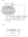
- Fig. 1 shows a schematic configuration of a fluorescence life measuring apparatus 1.
- the fluorescence life measuring apparatus 1 includes a disc-like stage (hereinafter referred to as "disc stage") 2, a laser light source 3, an optical system 4, a focus control unit 5, an imaging unit 6 and a measuring unit 7.
- the disc stage 2 is detachably supported on a rotating shaft SA through a through hole provided at the center of the disc stage 2.
- Fig. 2 shows a structure of the disc stage 2.
- the disc stage 2 has a layer structure in which a reflection film 2B and a fluorescence film 2C are formed in this order on one surface of a disc substrate 2A.
- the disc substrate 2A is formed of a material that becomes transparent when irradiated with light to excite the fluorescence film 2C (hereinafter referred to as "excitation light") and has a thickness of, for example, about 1.3 mm. Specifically, quartz is used as the material, for example.
- the reflection film 2B is formed of a material that can cause a predetermined amount of interface reflection and has a uniform thickness of, for example, about 100 nm. Specifically, titanium oxide is used as the material, for example, which causes about 20% of interface reflection when the excitation light has a wavelength of 405 nm and the disc substrate 2A is formed of quartz.
- the fluorescence film 2C is formed of an organic or inorganic material as a target of fluorescence life measurement and has a uniform thickness of, for example, about 100 nm.
- the laser light source 3 is positioned facing the surface of the disc substrate 2A other than the surface on which the reflection film 2B is formed and is configured to irradiate the fluorescence film 2C with the excitation light.
- the laser light source 3 used in this embodiment irradiates with the excitation light having a wavelength of 405 nm, an output power of 1 mW and a lateral mode of TEM00.
- the optical system 4 is configured to collect the excitation light irradiated by the laser light source 3 onto the interface between the disc substrate 2A and the reflection film 2B and guide the light reflected from the interface to the focus control unit 5.
- Fig. 3 shows a specific configuration example of the optical system 4.
- laser light emitted from the laser light source 3 as linearly polarized light parallel to the plane of paper is converted into parallel light by a collimator lens 11 and guided to a polarizing beam splitter 12. Then, in the optical system 4, laser light having passed through the polarizing beam splitter 12 is converted to circularly polarized light by a quarter wavelength plate 13 and collected onto the interface between the disc substrate 2A and the reflection film 2B by an objective lens 14.
- the fluorescent material to be measured formed as the fluorescence film 2C, is excited to emit fluorescence spatially isotropically.
- the optical system 4 light reflected from the interface between the disc substrate 2A and the reflection film 2B is guided through the objective lens 14 to the quarter wavelength plate 13 and converted to s-polarized light by the quarter wavelength plate 13. Then, in the optical system 4, the reflected light converted to s-polarized light is reflected by 90° from the polarizing beam splitter 12 and guided through a condensing lens 15 and a cylindrical lens 16 to the focus control unit 5 ( Fig. 1 ).
- the focus control unit 5 includes a light receiving unit for receiving light guided from the optical system 4.
- Fig. 4 shows the shape of light guided from the optical system 4 on the light receiving surface of the light receiving unit.
- the shape of light is circular as shown by broken line.
- the shape of light is elliptical as shown by alternate long and short dash line, due to aberration occurring in the cylindrical lens 16.
- the long axis and short axis of the elliptical shape alternate depending on whether the focus is short of or beyond the interface between the disc substrate 2A and the reflection film 2B.
- the focus control unit 5 generates focus control signal from the signal obtained from the light receiving unit as a result of photoelectric conversion in each of divided four regions. Specifically, in the example shown in Fig. 4 , signals of the regions A to D are obtained, then (A + D) - (B + C) is calculated to generate the focus control signal.
- the focus control unit 5 controls an actuator that can move in the optical axis direction according to the focus control signal to move the objective lens 14 ( Fig. 3 ) provided on the actuator so that the focus is positioned on the interface between the disc substrate 2A and the reflection film 2B.
- the imaging unit 6 is provided opposite the fluorescence film 2C of the disc stage 2 and is configured to image fluorescence emitted from the fluorescence film 2C and give the imaging result to the measuring unit 7 as imaging data.
- the measuring unit 7 is configured to calculate fluorescence life based on the imaging data given by the imaging unit 6.
- Fig. 5 shows a schematic configuration of the measuring unit 7.
- the measuring unit 7 is configured such that various hardware devices are connected to a CPU (Central Processing Unit) 21 via a bus 22.
- CPU Central Processing Unit
- the measuring unit 7 includes, as the hardware devices, at least a ROM (Read Only Memory) 23, a RAM (Random Access Memory) 24 as work memory of the CPU 21 and an interface 25.
- the measuring unit 7 also includes an input device 26 for inputting an instruction according to a user operation, a display 27 and a storage 28.
- the ROM 23 stores a program for performing fluorescence life measuring process (hereinafter referred to as "fluorescence life measuring program").
- the interface 25 is connected to a spindle motor SM attached to the rotating shaft SA ( Fig, 1 ), the laser light source 3, the focus control unit 5 and the imaging unit 6 ( Fig. 1 ).
- the CPU 21 expands in the RAM 24 the fluorescence life measuring program stored in the ROM 23 and functions as a driver 31, a preprocessor 32 and a fluorescence life calculator 33.
- the driver 31 drives the laser light source 3 to irradiate with the excitation light in a predetermined period and drives the focus control unit 5 so that the focus is positioned on the interface between the disc substrate 2A and the reflection film 2B. Further, the driver 31 drives the spindle motor SM to rotate at a constant linear speed and drives the imaging unit 6 to image in a predetermined period.
- Fig. 6 shows an imaging result of momentarily irradiating with the excitation light a predetermined position on the interface between the fluorescence disc substrate 2A and the reflection film 2B when the rotating disc stage 2 is at a position to be irradiated.
- a 14-bit digital still camera is used as the imaging unit 6, which includes a lens with a focal length of 6.33 to 19 mm and an 8.1 million pixel interlaced 1/2.5-inch CCD (Charge Coupled Device).
- the preprocessor 32 calculates the ratio of the strength at the tail position (the black circle area farthermost from the irradiated position in Fig. 6 ) to that at the head position (the black circle area nearest to the irradiated position in Fig. 6 ) of the afterglow of the fluorescence emitted at the irradiated position in an image represented by the imaging data given by the imaging unit 6.
- the preprocessor 32 adjusts the rotation speed of the disc stage 2 or the angle of view of the imaging unit 6 through the interface 25 so that the ratio falls within a defined range. Consequently, the afterglow from the irradiated position to a position at which a target strength is maintained (for example, a position just before disappearance) falls within the imaging range.
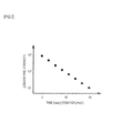
- the fluorescence life calculator 33 calculates the strength and elapsed time of the afterglow from the head position to the tail position at predetermined intervals (at black circles in Fig. 6 ) and creates a table showing the change of the afterglow over time (hereinafter referred to as "afterglow change table") based on the calculation result.
- Fig. 7 shows the afterglow change table for the afterglow shown in Fig. 6 .
- the elapsed time can be determined from the position information of the afterglow and the radius and rotation speed of the disc stage.
- the fluorescence film 2C ( Fig. 2 ) formed on the disc stage 2 is not limited to have a single excitation state, but may have multiple excitation states.
- the afterglow change table does not show a linear relationship as shown in Fig. 7 , but shows a mixture of multiple linear relationships depending on the number of the excitation states.
- the fluorescence life calculator 33 can calculate the fluorescence life of the fluorescence film 2C having multiple excitation states by designating linear portions having different gradients and curved portions of the slope in the afterglow change table as positions to be noted.
- the fluorescence life is calculated to be 1.8 msec when the linear speed of the disc stage 2 in imaging shown in Fig. 5 is 1 m/sec.
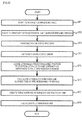
- the CPU 21 When an instruction to measure the fluorescence life is given, the CPU 21 starts the fluorescence life measuring process to proceed to a first step SP1. In the first step SP1, the CPU 21 drives the spindle motor SM to rotate the disc stage 2 at a constant linear speed, then proceeds to a second step SP2.
- the CPU 21 drives the laser light source 3 to irradiate the disc stage 2 with the excitation light in a predetermined period, then proceeds to a third step SP3.
- the CPU 21 drives the focus control unit 4 to position the focus on the interface between the disc substrate 2A and the reflection film 2B, then proceeds to a fourth step SP4.
- the CPU 21 drives the imaging unit 6 to start capturing an image at the time of irradiating the disc stage 2 with the excitation light, then proceeds to a fifth step SP5.
- the CPU 21 causes the afterglow from the irradiated position to a position at which a target strength is maintained (for example, a position just before disappearance) of the image captured in the fourth step SP4 to fall within the imaging range, then proceeds to a sixth step SP6.
- a target strength for example, a position just before disappearance
- the rotation speed of the disc stage 2 or the angle of view of the imaging unit 6 is adjusted so that the ratio of the strength at the tail position to that at the head position of the afterglow of the fluorescence emitted at the irradiated position falls within a defined range.
- the CPU 21 calculates the strength and elapsed time of the afterglow from the head position to the tail position at predetermined intervals, then proceeds to a seventh step SP7.
- the CPU 21 creates an afterglow change table based on the calculation result of the sixth step SP6, then proceeds to an eighth step SP8.
- the CPU 21 calculates the fluorescence life based on the equation (1), then ends the fluorescence life measuring process. Note that the CPU 21 is configured so that, when the slope created in the seventh step SP7 is nonlinear, the CPU 21 calculates the fluorescence life for each of linear portions having different gradients and curved portions of the slope shown in the afterglow change table in the eighth step SP8.
- the fluorescence life measuring apparatus 1 irradiates a fluorescent material placed on the rotating disc stage 2 with excitation light and images afterglow of emitted fluorescence caused by the excitation light in the imaging unit 6. Then, the fluorescence life measuring apparatus 1 detects the elapsed time from a fluorescence position and afterglow strength at a target afterglow position and calculates the fluorescence life from the afterglow strength and elapsed time.
- the fluorescence life measuring apparatus 1 captures the fluorescence life in the form of an afterglow image in the rotation direction, which allows obtaining of the strength change of light occurring in a short period without using a streak camera, resulting in a simple configuration of the fluorescence life.
- the fluorescence life measuring apparatus 1 momentarily irradiates the fluorescent material placed on the rotating disc stage 2 with laser light at a predetermined period.
- the fluorescence life measuring apparatus 1 can be configured more simply than the case of using pulsed laser light.
- the fluorescence life measuring apparatus 1 can reduce the property change of the fluorescent material caused by the excitation light in comparison with the case of continuously irradiating with pulsed laser light while measuring, which allows correctly measuring of the fluorescence life of the fluorescent material to be correctly measured.
- the fluorescence life measuring apparatus 1 calculates the fluorescence life for each of linear portions having different gradients and curved portions of those lines.
- the fluorescence life measuring apparatus 1 can calculate the fluorescence life of the fluorescent material.
- the fluorescence life measuring apparatus 1 captures the fluorescence life in the form of an afterglow image in the rotation direction, which allows obtaining of the strength change of light occurring in a short period without using a streak camera, resulting in a simple configuration of the fluorescence life.
- the rotation speed of the disc stage 2 or the angle of view of the imaging unit 6 is adjusted so that the ratio of the strength at the tail position to that at the head position of the imaged afterglow falls within a defined range.
- the angle of view of the imaging unit 6 may be fixed so that the entire disc stage 2 falls within the imaging range.
- This configuration allows calculating of the fluorescence life in a way similar to the above embodiment while keeping constant the ratio of the fluorescence strength and the afterglow strength within the imaging range, without the above-described adjustment.
- the above embodiment in which the rotation speed of the disc stage 2 or the angle of view of the imaging unit 6 is adjusted is preferable.
- the spindle motor SM is used to rotationally move the stage.
- the moving means is not limited to one that rotationally moves the stage.
- one that linearly moves the stage can be used.
- the moving means has only to be able to provide a constant moving speed in an entire process or a portion thereof.
- the fluorescent material to be measured is placed on the entire disc stage 2 in the form of a film.
- the placement position is not limited to the entire stage, and further, the placement may be performed in any other form than the film.
- the invention can be utilized in bio-based applications, such as gene testing, pharmaceutical origination or patient follow-up.
- 1 fluorescence life measuring apparatus 2 disc stage, 2A disc substrate, 2B reflection film, 2C fluorescence film, 3 laser light source, 4 optical system, 5 focus control unit, 6 imaging unit, 7 measuring unit, 21 CPU, 22 bus, 23 ROM, 24 RAM, 31 driver, 32 preprocessor, 33 fluorescence life calculator, SM spindle motor, SA rotating shaft
Landscapes
- Physics & Mathematics (AREA)
- Health & Medical Sciences (AREA)
- General Physics & Mathematics (AREA)
- Chemical & Material Sciences (AREA)
- Analytical Chemistry (AREA)
- Engineering & Computer Science (AREA)
- Multimedia (AREA)
- Biochemistry (AREA)
- Optics & Photonics (AREA)
- Life Sciences & Earth Sciences (AREA)
- Nuclear Medicine, Radiotherapy & Molecular Imaging (AREA)
- General Health & Medical Sciences (AREA)
- Immunology (AREA)
- Pathology (AREA)
- Computer Vision & Pattern Recognition (AREA)
- Investigating, Analyzing Materials By Fluorescence Or Luminescence (AREA)
Abstract
Description
- The present invention relates to a fluorescence life measuring apparatus, a fluorescence life measuring method and a program, which is useful in a field in which a technique of detecting the life of emitted light caused by irradiation of excitation light is used.
- Conventionally, a fluorescence life measuring apparatus has been proposed that irradiates a specimen supported in a cell with pulsed excitation light, measures the time waveform of emitted fluorescence caused by the excitation light using a photomultiplier tube or streak camera, and obtains the fluorescence life from the measurement result (for example, see Patent Document 1).
-
-
Patent Document 1JP-A-2001-349833 - However, the photomultiplier tube or streak camera is relatively large itself, which makes such a fluorescence life measuring apparatus large as a whole. Also, in this fluorescence life measuring apparatus, a light source for irradiating with pulsed excitation light is used, and the photomultiplier tube or streak camera needs to be driven according to the timing of irradiation from the light source, which requires complicated and time-consuming adjustment process of the photomultiplier tube or streak camera.
- In view of the above, the invention proposes a fluorescence life measuring apparatus, a fluorescence life measuring method and a program that can obtain fluorescence life using a simple configuration.
- In order to solve the above problems, the invention provides a fluorescence life measuring apparatus including: a moving means for moving a stage on which a fluorescent material to be measured is placed; an irradiating means for irradiating with excitation light the fluorescent material placed on the stage moved at a constant speed by the moving means; an imaging means for imaging afterglow of emitted fluorescence caused by the excitation light; and a fluorescence life calculating means for using an image imaged by the imaging unit to detect the elapsed time from a fluorescence position and afterglow strength at a target afterglow position and calculate the fluorescence life.
- Also, the invention provides a fluorescence life measuring method including: a moving control step of moving a stage on which a fluorescent material to be measured is placed; an irradiating step of irradiating with excitation light the fluorescent material placed on the stage moved at a constant speed through the control in the moving control step; an imaging step of imaging afterglow of emitted fluorescence caused by the excitation light; and a fluorescence life calculating step of using an image imaged in the imaging step to detect the elapsed time from a fluorescence position and afterglow strength at a target afterglow position and calculate the fluorescence life.
- Also, the invention provides a program for causing: a moving control means to move a stage on which a fluorescent material to be measured is placed; an irradiating means to irradiate with excitation light the fluorescent material placed on the stage moved at a constant speed by the moving control means; an imaging means to image afterglow of emitted fluorescence caused by the excitation light; and a calculating unit to use an image imaged by the imaging means to detect the elapsed time from a fluorescence position and afterglow strength at a target afterglow position and calculate the fluorescence life.
- According to the invention, the fluorescence life measuring apparatus captures the fluorescence life in the form of an afterglow image in the moving direction, which allows obtaining of the strength change of light occurring in a short period with a common camera rather than a photomultiplier tube or streak camera, resulting in a simple configuration of the fluorescence life.
-
-
Fig. 1 schematically shows a configuration of a fluorescence life measuring apparatus. -
Fig. 2 schematically shows a structure of a disc stage. -
Fig. 3 shows a configuration example of an optical system. -
Fig. 4 schematically shows a beam shape on a light receiving surface. -
Fig. 5 is a block diagram showing a configuration of a measuring unit. -
Fig. 6 is a photograph of an imaging result when excitation light is irradiated. -
Fig. 7 is a graph showing afterglow strength change over time. -
Fig. 8 is a flowchart showing a fluorescence life measuring process. - An embodiments in accordance with the invention is described below. The description is made in the following order:
-
- [1-1. Configuration of fluorescence life measuring apparatus];
- [1-2. Specific configuration of measuring unit];
- [1-3. Fluorescence life measuring process];
- [1-4. Effect etc.]; and
- As an embodiment in accordance with the invention, a fluorescence life measuring apparatus is described.
-
Fig. 1 shows a schematic configuration of a fluorescencelife measuring apparatus 1. The fluorescencelife measuring apparatus 1 includes a disc-like stage (hereinafter referred to as "disc stage") 2, alaser light source 3, an optical system 4, afocus control unit 5, animaging unit 6 and a measuring unit 7. - The
disc stage 2 is detachably supported on a rotating shaft SA through a through hole provided at the center of thedisc stage 2.Fig. 2 shows a structure of thedisc stage 2. Thedisc stage 2 has a layer structure in which a reflection film 2B and a fluorescence film 2C are formed in this order on one surface of adisc substrate 2A. - The
disc substrate 2A is formed of a material that becomes transparent when irradiated with light to excite the fluorescence film 2C (hereinafter referred to as "excitation light") and has a thickness of, for example, about 1.3 mm. Specifically, quartz is used as the material, for example. - The reflection film 2B is formed of a material that can cause a predetermined amount of interface reflection and has a uniform thickness of, for example, about 100 nm. Specifically, titanium oxide is used as the material, for example, which causes about 20% of interface reflection when the excitation light has a wavelength of 405 nm and the
disc substrate 2A is formed of quartz. - The fluorescence film 2C is formed of an organic or inorganic material as a target of fluorescence life measurement and has a uniform thickness of, for example, about 100 nm.
- The
laser light source 3 is positioned facing the surface of thedisc substrate 2A other than the surface on which the reflection film 2B is formed and is configured to irradiate the fluorescence film 2C with the excitation light. Thelaser light source 3 used in this embodiment irradiates with the excitation light having a wavelength of 405 nm, an output power of 1 mW and a lateral mode of TEM00. - The optical system 4 is configured to collect the excitation light irradiated by the
laser light source 3 onto the interface between thedisc substrate 2A and the reflection film 2B and guide the light reflected from the interface to thefocus control unit 5.Fig. 3 shows a specific configuration example of the optical system 4. - In the optical system 4, laser light emitted from the
laser light source 3 as linearly polarized light parallel to the plane of paper is converted into parallel light by a collimator lens 11 and guided to a polarizing beam splitter 12. Then, in the optical system 4, laser light having passed through the polarizing beam splitter 12 is converted to circularly polarized light by aquarter wavelength plate 13 and collected onto the interface between thedisc substrate 2A and the reflection film 2B by anobjective lens 14. - When the excitation light passes through the reflection film 2B and reaches the fluorescence film 2C, the fluorescent material to be measured, formed as the fluorescence film 2C, is excited to emit fluorescence spatially isotropically.
- Also in the optical system 4, light reflected from the interface between the
disc substrate 2A and the reflection film 2B is guided through theobjective lens 14 to thequarter wavelength plate 13 and converted to s-polarized light by thequarter wavelength plate 13. Then, in the optical system 4, the reflected light converted to s-polarized light is reflected by 90° from the polarizing beam splitter 12 and guided through a condensinglens 15 and acylindrical lens 16 to the focus control unit 5 (Fig. 1 ). - The
focus control unit 5 includes a light receiving unit for receiving light guided from the optical system 4. Here,Fig. 4 shows the shape of light guided from the optical system 4 on the light receiving surface of the light receiving unit. When the focus is on the interface between thedisc substrate 2A and the reflection film 2B, the shape of light is circular as shown by broken line. On the other hand, when the focus is off the interface, the shape of light is elliptical as shown by alternate long and short dash line, due to aberration occurring in thecylindrical lens 16. Specifically, the long axis and short axis of the elliptical shape alternate depending on whether the focus is short of or beyond the interface between thedisc substrate 2A and the reflection film 2B. - The
focus control unit 5 generates focus control signal from the signal obtained from the light receiving unit as a result of photoelectric conversion in each of divided four regions. Specifically, in the example shown inFig. 4 , signals of the regions A to D are obtained, then (A + D) - (B + C) is calculated to generate the focus control signal. - The
focus control unit 5 controls an actuator that can move in the optical axis direction according to the focus control signal to move the objective lens 14 (Fig. 3 ) provided on the actuator so that the focus is positioned on the interface between thedisc substrate 2A and the reflection film 2B. - The
imaging unit 6 is provided opposite the fluorescence film 2C of thedisc stage 2 and is configured to image fluorescence emitted from the fluorescence film 2C and give the imaging result to the measuring unit 7 as imaging data. - The measuring unit 7 is configured to calculate fluorescence life based on the imaging data given by the
imaging unit 6. - Next, the measuring unit 7 is specifically described.
Fig. 5 shows a schematic configuration of the measuring unit 7. The measuring unit 7 is configured such that various hardware devices are connected to a CPU (Central Processing Unit) 21 via a bus 22. - The measuring unit 7 includes, as the hardware devices, at least a ROM (Read Only Memory) 23, a RAM (Random Access Memory) 24 as work memory of the
CPU 21 and aninterface 25. In this embodiment, the measuring unit 7 also includes aninput device 26 for inputting an instruction according to a user operation, adisplay 27 and astorage 28. - The
ROM 23 stores a program for performing fluorescence life measuring process (hereinafter referred to as "fluorescence life measuring program"). Theinterface 25 is connected to a spindle motor SM attached to the rotating shaft SA (Fig, 1 ), thelaser light source 3, thefocus control unit 5 and the imaging unit 6 (Fig. 1 ). - When an instruction to measure the fluorescence life is given from the operation input device, the
CPU 21 expands in theRAM 24 the fluorescence life measuring program stored in theROM 23 and functions as adriver 31, apreprocessor 32 and afluorescence life calculator 33. - The
driver 31 drives thelaser light source 3 to irradiate with the excitation light in a predetermined period and drives thefocus control unit 5 so that the focus is positioned on the interface between thedisc substrate 2A and the reflection film 2B. Further, thedriver 31 drives the spindle motor SM to rotate at a constant linear speed and drives theimaging unit 6 to image in a predetermined period. - Here,
Fig. 6 shows an imaging result of momentarily irradiating with the excitation light a predetermined position on the interface between thefluorescence disc substrate 2A and the reflection film 2B when therotating disc stage 2 is at a position to be irradiated. Note that, inFig. 6 , a 14-bit digital still camera is used as theimaging unit 6, which includes a lens with a focal length of 6.33 to 19 mm and an 8.1 million pixel interlaced 1/2.5-inch CCD (Charge Coupled Device). - As seen from
Fig. 6 , when the fluorescence film 2C of therotating disc stage 2 is momentarily excited at the irradiated position, fluorescence emitted at the irradiated position is imaged as an afterglow in the rotation direction. - The
preprocessor 32 calculates the ratio of the strength at the tail position (the black circle area farthermost from the irradiated position inFig. 6 ) to that at the head position (the black circle area nearest to the irradiated position inFig. 6 ) of the afterglow of the fluorescence emitted at the irradiated position in an image represented by the imaging data given by theimaging unit 6. - Then, the
preprocessor 32 adjusts the rotation speed of thedisc stage 2 or the angle of view of theimaging unit 6 through theinterface 25 so that the ratio falls within a defined range. Consequently, the afterglow from the irradiated position to a position at which a target strength is maintained (for example, a position just before disappearance) falls within the imaging range. - When the rotation speed of the
disc stage 2 or the angle of view of theimaging unit 6 has been adjusted, thefluorescence life calculator 33 calculates the strength and elapsed time of the afterglow from the head position to the tail position at predetermined intervals (at black circles inFig. 6 ) and creates a table showing the change of the afterglow over time (hereinafter referred to as "afterglow change table") based on the calculation result.Fig. 7 shows the afterglow change table for the afterglow shown inFig. 6 . - The elapsed time can be determined from the position information of the afterglow and the radius and rotation speed of the disc stage.
- Then, the
fluorescence life calculator 33 calculates the fluorescence life based on the following equation:
where I(t) is the afterglow strength at the positions to be noted (afterglow strength change over time), I0 is the strength at the irradiated position, t is the elapsed time at the positions to be noted, and T is the fluorescence life. Further, - t/τ means the gradient of the afterglow change table (Fig. 6 ). - By the way, the fluorescence film 2C (
Fig. 2 ) formed on thedisc stage 2 is not limited to have a single excitation state, but may have multiple excitation states. When the fluorescence film 2C has multiple excitation states, the afterglow change table does not show a linear relationship as shown inFig. 7 , but shows a mixture of multiple linear relationships depending on the number of the excitation states. - In this case, the
fluorescence life calculator 33 can calculate the fluorescence life of the fluorescence film 2C having multiple excitation states by designating linear portions having different gradients and curved portions of the slope in the afterglow change table as positions to be noted. - For the fluorescence film 2C presenting the slope shown in
Fig. 6 , the fluorescence life is calculated to be 1.8 msec when the linear speed of thedisc stage 2 in imaging shown inFig. 5 is 1 m/sec. - Next, a fluorescence life measuring process of the measuring unit 7 is described with reference to a flowchart shown in
Fig. 8 . - When an instruction to measure the fluorescence life is given, the
CPU 21 starts the fluorescence life measuring process to proceed to a first step SP1. In the first step SP1, theCPU 21 drives the spindle motor SM to rotate thedisc stage 2 at a constant linear speed, then proceeds to a second step SP2. - In the second step SP2, the
CPU 21 drives thelaser light source 3 to irradiate thedisc stage 2 with the excitation light in a predetermined period, then proceeds to a third step SP3. In the third step SP3, theCPU 21 drives the focus control unit 4 to position the focus on the interface between thedisc substrate 2A and the reflection film 2B, then proceeds to a fourth step SP4. - In the fourth step SP4, the
CPU 21 drives theimaging unit 6 to start capturing an image at the time of irradiating thedisc stage 2 with the excitation light, then proceeds to a fifth step SP5. - In the fifth step SP5, the
CPU 21 causes the afterglow from the irradiated position to a position at which a target strength is maintained (for example, a position just before disappearance) of the image captured in the fourth step SP4 to fall within the imaging range, then proceeds to a sixth step SP6. Specifically, as described above, the rotation speed of thedisc stage 2 or the angle of view of theimaging unit 6 is adjusted so that the ratio of the strength at the tail position to that at the head position of the afterglow of the fluorescence emitted at the irradiated position falls within a defined range. - In the sixth step SP6, the
CPU 21 calculates the strength and elapsed time of the afterglow from the head position to the tail position at predetermined intervals, then proceeds to a seventh step SP7. In the seventh step SP7, theCPU 21 creates an afterglow change table based on the calculation result of the sixth step SP6, then proceeds to an eighth step SP8. - In the eighth step SP8, the
CPU 21 calculates the fluorescence life based on the equation (1), then ends the fluorescence life measuring process. Note that theCPU 21 is configured so that, when the slope created in the seventh step SP7 is nonlinear, theCPU 21 calculates the fluorescence life for each of linear portions having different gradients and curved portions of the slope shown in the afterglow change table in the eighth step SP8. - In the above configuration, the fluorescence
life measuring apparatus 1 irradiates a fluorescent material placed on therotating disc stage 2 with excitation light and images afterglow of emitted fluorescence caused by the excitation light in theimaging unit 6. Then, the fluorescencelife measuring apparatus 1 detects the elapsed time from a fluorescence position and afterglow strength at a target afterglow position and calculates the fluorescence life from the afterglow strength and elapsed time. - The fluorescence
life measuring apparatus 1 captures the fluorescence life in the form of an afterglow image in the rotation direction, which allows obtaining of the strength change of light occurring in a short period without using a streak camera, resulting in a simple configuration of the fluorescence life. - Furthermore, the fluorescence
life measuring apparatus 1 momentarily irradiates the fluorescent material placed on therotating disc stage 2 with laser light at a predetermined period. Thus, the fluorescencelife measuring apparatus 1 can be configured more simply than the case of using pulsed laser light. Also, the fluorescencelife measuring apparatus 1 can reduce the property change of the fluorescent material caused by the excitation light in comparison with the case of continuously irradiating with pulsed laser light while measuring, which allows correctly measuring of the fluorescence life of the fluorescent material to be correctly measured. - Furthermore, when lines showing the afterglow strength change over time are nonlinear, the fluorescence
life measuring apparatus 1 calculates the fluorescence life for each of linear portions having different gradients and curved portions of those lines. - Thus, even when the fluorescent material has multiple excitation states, the fluorescence
life measuring apparatus 1 can calculate the fluorescence life of the fluorescent material. - According to the above configuration, the fluorescence
life measuring apparatus 1 captures the fluorescence life in the form of an afterglow image in the rotation direction, which allows obtaining of the strength change of light occurring in a short period without using a streak camera, resulting in a simple configuration of the fluorescence life. - In the above embodiment, before calculating the fluorescence life, the rotation speed of the
disc stage 2 or the angle of view of theimaging unit 6 is adjusted so that the ratio of the strength at the tail position to that at the head position of the imaged afterglow falls within a defined range. - Rather than this embodiment, the angle of view of the
imaging unit 6 may be fixed so that theentire disc stage 2 falls within the imaging range. This configuration allows calculating of the fluorescence life in a way similar to the above embodiment while keeping constant the ratio of the fluorescence strength and the afterglow strength within the imaging range, without the above-described adjustment. However, in terms of afterglow sensitivity, the above embodiment in which the rotation speed of thedisc stage 2 or the angle of view of theimaging unit 6 is adjusted is preferable. - Furthermore, in the above embodiment, as an moving means for moving the stage on which a fluorescent material to be measured is placed, the spindle motor SM is used to rotationally move the stage. However, the moving means is not limited to one that rotationally moves the stage. For example, one that linearly moves the stage can be used. Anyway, the moving means has only to be able to provide a constant moving speed in an entire process or a portion thereof.
- Furthermore, in the above embodiment, the fluorescent material to be measured is placed on the
entire disc stage 2 in the form of a film. However, the placement position is not limited to the entire stage, and further, the placement may be performed in any other form than the film. - The invention can be utilized in bio-based applications, such as gene testing, pharmaceutical origination or patient follow-up.
- 1 fluorescence life measuring apparatus, 2 disc stage, 2A disc substrate, 2B reflection film, 2C fluorescence film, 3 laser light source, 4 optical system, 5 focus control unit, 6 imaging unit, 7 measuring unit, 21 CPU, 22 bus, 23 ROM, 24 RAM, 31 driver, 32 preprocessor, 33 fluorescence life calculator, SM spindle motor, SA rotating shaft
Claims (6)
- A fluorescence life measuring apparatus comprising:a moving means for moving a stage on which a fluorescent material to be measured is placed;an irradiating means for irradiating with excitation light the fluorescent material placed on the stage moved at a constant speed by the moving means;an imaging means for imaging afterglow of emitted fluorescence caused by the excitation light; anda fluorescence life calculating means for using an image imaged by the imaging unit to detect the elapsed time from a fluorescence position and afterglow strength at a target afterglow position and calculate the fluorescence life.
- The fluorescence life measuring apparatus according to Claim 1,
wherein the fluorescence life calculating means, when lines showing the afterglow strength change over time are nonlinear, calculates the fluorescence life for each of linear portions having different gradients and curved portions of those lines. - The fluorescence life measuring apparatus according to Claim 2,
further comprising adjusting means for adjusting the moving speed of the moving means or the angle of view of the imaging means so that the ratio of the strength at the tail position to that at the head position of the imaged afterglow falls within a defined range,
wherein the fluorescence life calculating means calculates the fluorescence life from the images after the adjustment is performed by the adjusting means. - The fluorescence life measuring apparatus according to Claim 3, wherein the moving means rotationally moves the stage on which the fluorescent material to be measured is placed.
- A fluorescence life measuring method comprising:a moving control step of moving a stage on which a fluorescent material to be measured is placed;an irradiating step of irradiating with excitation light the fluorescent material placed on the stage moved at a constant speed through the control in the moving control step;an imaging step of imaging afterglow of emitted fluorescence caused by the excitation light; anda fluorescence life calculating step of using an image imaged in the imaging step to detect the elapsed time from a fluorescence position and afterglow strength at a target afterglow position and calculate the fluorescence life.
- A program for causing:a moving control means to move a stage on which a fluorescent material to be measured is placed;an irradiating means to irradiate with excitation light the fluorescent material placed on the stage moved at a constant speed by the moving control means;an imaging means to image afterglow of emitted fluorescence caused by the excitation light; anda calculating unit to use an image imaged by the imaging means to detect the elapsed time from a fluorescence position and afterglow strength at a target afterglow position and calculate the fluorescence life.
Applications Claiming Priority (2)
| Application Number | Priority Date | Filing Date | Title |
|---|---|---|---|
| JP2009007722A JP5169857B2 (en) | 2009-01-16 | 2009-01-16 | Fluorescence lifetime measuring apparatus, fluorescence lifetime measuring method and program |
| PCT/JP2010/050364 WO2010082611A1 (en) | 2009-01-16 | 2010-01-07 | Fluorescence life measuring device, fluorescence life measuring method, and program |
Publications (3)
| Publication Number | Publication Date |
|---|---|
| EP2381241A1 true EP2381241A1 (en) | 2011-10-26 |
| EP2381241A4 EP2381241A4 (en) | 2014-07-23 |
| EP2381241B1 EP2381241B1 (en) | 2020-03-18 |
Family
ID=42339865
Family Applications (1)
| Application Number | Title | Priority Date | Filing Date |
|---|---|---|---|
| EP10731280.3A Not-in-force EP2381241B1 (en) | 2009-01-16 | 2010-01-07 | Fluorescence lifetime measuring device, fluorescence lifetime measuring method, and program |
Country Status (5)
| Country | Link |
|---|---|
| US (1) | US8618506B2 (en) |
| EP (1) | EP2381241B1 (en) |
| JP (1) | JP5169857B2 (en) |
| CN (1) | CN102272583B (en) |
| WO (1) | WO2010082611A1 (en) |
Cited By (1)
| Publication number | Priority date | Publication date | Assignee | Title |
|---|---|---|---|---|
| CN103592277A (en) * | 2013-11-20 | 2014-02-19 | 中国科学技术大学 | High-precision fluorescent lifetime measuring device |
Families Citing this family (8)
| Publication number | Priority date | Publication date | Assignee | Title |
|---|---|---|---|---|
| JP2012132742A (en) * | 2010-12-21 | 2012-07-12 | Fujifilm Corp | Time-resolved fluorescence measuring device and method |
| CN105300949B (en) * | 2015-11-26 | 2019-06-11 | 浙江大学 | Method and device for measuring fluorescence lifetime |
| CN107860756A (en) * | 2017-11-12 | 2018-03-30 | 武汉能斯特科技有限公司 | A kind of method and apparatus for measuring fluorescence lifetime |
| CN109100021A (en) * | 2018-02-27 | 2018-12-28 | 武汉能斯特科技有限公司 | A kind of time-resolved spectrum and lifetime measurement module and device |
| CN110632039B (en) * | 2018-06-22 | 2025-02-14 | 武汉能斯特科技有限公司 | A rotating disk and device for high-throughput measurement of fluorescence phosphorescence lifetime |
| EP3855165A4 (en) * | 2018-09-18 | 2022-05-25 | The University of Tokyo | SUBSTANCE SPECIFICATION DEVICE, SUBSTANCE SPECIFICATION METHOD AND SUBSTANCE SPECIFICATION PROGRAM |
| WO2021187536A1 (en) | 2020-03-17 | 2021-09-23 | 国立大学法人東京大学 | State identification device, state identification method, and state identification program |
| CN116298364A (en) * | 2023-02-10 | 2023-06-23 | 南昌航空大学 | An Optical Method for Detecting Rotational State |
Family Cites Families (9)
| Publication number | Priority date | Publication date | Assignee | Title |
|---|---|---|---|---|
| JPS61241639A (en) | 1985-04-19 | 1986-10-27 | Hitachi Ltd | Reaction sample analyzer |
| JP3154815B2 (en) * | 1992-06-24 | 2001-04-09 | 株式会社東芝 | Phosphor detection device and phosphor detection method |
| JP2000304698A (en) | 1999-04-16 | 2000-11-02 | Canon Inc | Fluorescence measurement method and apparatus and substrate suitable therefor |
| JP3597729B2 (en) | 1999-05-11 | 2004-12-08 | 日立ソフトウエアエンジニアリング株式会社 | Fluorescence metering method and fluorescence meter |
| JP4459390B2 (en) | 2000-06-08 | 2010-04-28 | 浜松ホトニクス株式会社 | Fluorescence measurement method, fluorescence measurement apparatus, and sample evaluation apparatus using the same |
| JP4074136B2 (en) * | 2002-05-29 | 2008-04-09 | 浜松ホトニクス株式会社 | Fluorescence lifetime distribution image measuring apparatus and measuring method thereof |
| JP2007033170A (en) * | 2005-07-26 | 2007-02-08 | Fujifilm Corp | Fluorescence detection method and fluorescence detection system |
| JP2008122297A (en) * | 2006-11-14 | 2008-05-29 | Fujitsu Ltd | Fluorescence detection apparatus and fluorescence detection method |
| JP5208801B2 (en) * | 2009-02-20 | 2013-06-12 | 株式会社東芝 | Photodetection device and paper sheet processing apparatus provided with the photodetection device |
-
2009
- 2009-01-16 JP JP2009007722A patent/JP5169857B2/en not_active Expired - Fee Related
-
2010
- 2010-01-07 WO PCT/JP2010/050364 patent/WO2010082611A1/en not_active Ceased
- 2010-01-07 CN CN201080004129.XA patent/CN102272583B/en not_active Expired - Fee Related
- 2010-01-07 EP EP10731280.3A patent/EP2381241B1/en not_active Not-in-force
- 2010-01-07 US US13/143,518 patent/US8618506B2/en not_active Expired - Fee Related
Cited By (2)
| Publication number | Priority date | Publication date | Assignee | Title |
|---|---|---|---|---|
| CN103592277A (en) * | 2013-11-20 | 2014-02-19 | 中国科学技术大学 | High-precision fluorescent lifetime measuring device |
| CN103592277B (en) * | 2013-11-20 | 2017-01-11 | 中国科学技术大学 | High-precision fluorescent lifetime measuring device |
Also Published As
| Publication number | Publication date |
|---|---|
| WO2010082611A1 (en) | 2010-07-22 |
| JP2010164468A (en) | 2010-07-29 |
| JP5169857B2 (en) | 2013-03-27 |
| US8618506B2 (en) | 2013-12-31 |
| US20110266458A1 (en) | 2011-11-03 |
| CN102272583B (en) | 2014-02-26 |
| EP2381241B1 (en) | 2020-03-18 |
| EP2381241A4 (en) | 2014-07-23 |
| CN102272583A (en) | 2011-12-07 |
Similar Documents
| Publication | Publication Date | Title |
|---|---|---|
| EP2381241B1 (en) | Fluorescence lifetime measuring device, fluorescence lifetime measuring method, and program | |
| US8063386B2 (en) | Time resolved fluorescent imaging system | |
| JP2722362B2 (en) | Method and apparatus for measuring particle or defect size information | |
| US10620124B2 (en) | Optical analysis device and biomolecular analysis device | |
| JP2975991B2 (en) | Polarization measurement method and apparatus | |
| KR101835815B1 (en) | Apparatus and method for measuring fluorescence lifetime | |
| JP2001194303A (en) | Device for analyzing diffusion motion of fluorescent molecule | |
| JPH10281876A (en) | Polarizing imaging device | |
| JP2001056303A (en) | X-ray stress measuring apparatus | |
| CN119619080A (en) | A micro-area scanning imaging device and a measuring method | |
| JP2004184379A (en) | Microarray reading method | |
| JP2007071831A (en) | Optical material evaluation method and apparatus | |
| JP2005043278A (en) | Fluorescence correlation spectroscopy measuring apparatus and diffusion coefficient measuring method in heterogeneous sample | |
| CN220231488U (en) | Imaging system and nucleic acid fragment analysis apparatus | |
| JP2002176009A (en) | Laser annealing crystallization in-situ analyzer | |
| JP2010038868A (en) | Optical viscosity measuring system | |
| CN102192879A (en) | Unmarked high throughput detecting device of biological chip by using light reflection differential method | |
| CN114813662B (en) | Second harmonic measurement method and instrument | |
| CN101153870A (en) | A device for label-free monitoring of microarray biomolecular reactions | |
| TWI608227B (en) | Optical surface scanning systems and methods | |
| JP2000241349A (en) | Polarimeter | |
| JP2001272355A (en) | Foreign matter inspecting apparatus | |
| JPH10104079A (en) | Depolarized imaging device | |
| JP4002818B2 (en) | measuring device | |
| US9134240B2 (en) | System and method for evaluating material in rotary motion |
Legal Events
| Date | Code | Title | Description |
|---|---|---|---|
| PUAI | Public reference made under article 153(3) epc to a published international application that has entered the european phase |
Free format text: ORIGINAL CODE: 0009012 |
|
| 17P | Request for examination filed |
Effective date: 20110708 |
|
| AK | Designated contracting states |
Kind code of ref document: A1 Designated state(s): AT BE BG CH CY CZ DE DK EE ES FI FR GB GR HR HU IE IS IT LI LT LU LV MC MK MT NL NO PL PT RO SE SI SK SM TR |
|
| DAX | Request for extension of the european patent (deleted) | ||
| A4 | Supplementary search report drawn up and despatched |
Effective date: 20140623 |
|
| RIC1 | Information provided on ipc code assigned before grant |
Ipc: G02B 21/36 20060101ALI20140616BHEP Ipc: G01N 21/64 20060101AFI20140616BHEP |
|
| RIC1 | Information provided on ipc code assigned before grant |
Ipc: G02B 21/36 20060101ALI20190731BHEP Ipc: G01N 21/64 20060101AFI20190731BHEP Ipc: G02B 21/16 20060101ALI20190731BHEP |
|
| GRAP | Despatch of communication of intention to grant a patent |
Free format text: ORIGINAL CODE: EPIDOSNIGR1 |
|
| STAA | Information on the status of an ep patent application or granted ep patent |
Free format text: STATUS: GRANT OF PATENT IS INTENDED |
|
| INTG | Intention to grant announced |
Effective date: 20190911 |
|
| GRAS | Grant fee paid |
Free format text: ORIGINAL CODE: EPIDOSNIGR3 |
|
| GRAJ | Information related to disapproval of communication of intention to grant by the applicant or resumption of examination proceedings by the epo deleted |
Free format text: ORIGINAL CODE: EPIDOSDIGR1 |
|
| GRAL | Information related to payment of fee for publishing/printing deleted |
Free format text: ORIGINAL CODE: EPIDOSDIGR3 |
|
| STAA | Information on the status of an ep patent application or granted ep patent |
Free format text: STATUS: REQUEST FOR EXAMINATION WAS MADE |
|
| GRAR | Information related to intention to grant a patent recorded |
Free format text: ORIGINAL CODE: EPIDOSNIGR71 |
|
| STAA | Information on the status of an ep patent application or granted ep patent |
Free format text: STATUS: GRANT OF PATENT IS INTENDED |
|
| INTC | Intention to grant announced (deleted) | ||
| GRAA | (expected) grant |
Free format text: ORIGINAL CODE: 0009210 |
|
| STAA | Information on the status of an ep patent application or granted ep patent |
Free format text: STATUS: THE PATENT HAS BEEN GRANTED |
|
| AK | Designated contracting states |
Kind code of ref document: B1 Designated state(s): AT BE BG CH CY CZ DE DK EE ES FI FR GB GR HR HU IE IS IT LI LT LU LV MC MK MT NL NO PL PT RO SE SI SK SM TR |
|
| INTG | Intention to grant announced |
Effective date: 20200211 |
|
| REG | Reference to a national code |
Ref country code: GB Ref legal event code: FG4D |
|
| REG | Reference to a national code |
Ref country code: DE Ref legal event code: R096 Ref document number: 602010063550 Country of ref document: DE |
|
| REG | Reference to a national code |
Ref country code: AT Ref legal event code: REF Ref document number: 1246478 Country of ref document: AT Kind code of ref document: T Effective date: 20200415 Ref country code: IE Ref legal event code: FG4D |
|
| PG25 | Lapsed in a contracting state [announced via postgrant information from national office to epo] |
Ref country code: NO Free format text: LAPSE BECAUSE OF FAILURE TO SUBMIT A TRANSLATION OF THE DESCRIPTION OR TO PAY THE FEE WITHIN THE PRESCRIBED TIME-LIMIT Effective date: 20200618 Ref country code: FI Free format text: LAPSE BECAUSE OF FAILURE TO SUBMIT A TRANSLATION OF THE DESCRIPTION OR TO PAY THE FEE WITHIN THE PRESCRIBED TIME-LIMIT Effective date: 20200318 |
|
| REG | Reference to a national code |
Ref country code: NL Ref legal event code: MP Effective date: 20200318 |
|
| PG25 | Lapsed in a contracting state [announced via postgrant information from national office to epo] |
Ref country code: BG Free format text: LAPSE BECAUSE OF FAILURE TO SUBMIT A TRANSLATION OF THE DESCRIPTION OR TO PAY THE FEE WITHIN THE PRESCRIBED TIME-LIMIT Effective date: 20200618 Ref country code: SE Free format text: LAPSE BECAUSE OF FAILURE TO SUBMIT A TRANSLATION OF THE DESCRIPTION OR TO PAY THE FEE WITHIN THE PRESCRIBED TIME-LIMIT Effective date: 20200318 Ref country code: LV Free format text: LAPSE BECAUSE OF FAILURE TO SUBMIT A TRANSLATION OF THE DESCRIPTION OR TO PAY THE FEE WITHIN THE PRESCRIBED TIME-LIMIT Effective date: 20200318 Ref country code: GR Free format text: LAPSE BECAUSE OF FAILURE TO SUBMIT A TRANSLATION OF THE DESCRIPTION OR TO PAY THE FEE WITHIN THE PRESCRIBED TIME-LIMIT Effective date: 20200619 Ref country code: HR Free format text: LAPSE BECAUSE OF FAILURE TO SUBMIT A TRANSLATION OF THE DESCRIPTION OR TO PAY THE FEE WITHIN THE PRESCRIBED TIME-LIMIT Effective date: 20200318 |
|
| REG | Reference to a national code |
Ref country code: LT Ref legal event code: MG4D |
|
| PG25 | Lapsed in a contracting state [announced via postgrant information from national office to epo] |
Ref country code: NL Free format text: LAPSE BECAUSE OF FAILURE TO SUBMIT A TRANSLATION OF THE DESCRIPTION OR TO PAY THE FEE WITHIN THE PRESCRIBED TIME-LIMIT Effective date: 20200318 |
|
| PG25 | Lapsed in a contracting state [announced via postgrant information from national office to epo] |
Ref country code: EE Free format text: LAPSE BECAUSE OF FAILURE TO SUBMIT A TRANSLATION OF THE DESCRIPTION OR TO PAY THE FEE WITHIN THE PRESCRIBED TIME-LIMIT Effective date: 20200318 Ref country code: SM Free format text: LAPSE BECAUSE OF FAILURE TO SUBMIT A TRANSLATION OF THE DESCRIPTION OR TO PAY THE FEE WITHIN THE PRESCRIBED TIME-LIMIT Effective date: 20200318 Ref country code: PT Free format text: LAPSE BECAUSE OF FAILURE TO SUBMIT A TRANSLATION OF THE DESCRIPTION OR TO PAY THE FEE WITHIN THE PRESCRIBED TIME-LIMIT Effective date: 20200812 Ref country code: LT Free format text: LAPSE BECAUSE OF FAILURE TO SUBMIT A TRANSLATION OF THE DESCRIPTION OR TO PAY THE FEE WITHIN THE PRESCRIBED TIME-LIMIT Effective date: 20200318 Ref country code: RO Free format text: LAPSE BECAUSE OF FAILURE TO SUBMIT A TRANSLATION OF THE DESCRIPTION OR TO PAY THE FEE WITHIN THE PRESCRIBED TIME-LIMIT Effective date: 20200318 Ref country code: IS Free format text: LAPSE BECAUSE OF FAILURE TO SUBMIT A TRANSLATION OF THE DESCRIPTION OR TO PAY THE FEE WITHIN THE PRESCRIBED TIME-LIMIT Effective date: 20200718 Ref country code: SK Free format text: LAPSE BECAUSE OF FAILURE TO SUBMIT A TRANSLATION OF THE DESCRIPTION OR TO PAY THE FEE WITHIN THE PRESCRIBED TIME-LIMIT Effective date: 20200318 Ref country code: CZ Free format text: LAPSE BECAUSE OF FAILURE TO SUBMIT A TRANSLATION OF THE DESCRIPTION OR TO PAY THE FEE WITHIN THE PRESCRIBED TIME-LIMIT Effective date: 20200318 |
|
| REG | Reference to a national code |
Ref country code: AT Ref legal event code: MK05 Ref document number: 1246478 Country of ref document: AT Kind code of ref document: T Effective date: 20200318 |
|
| REG | Reference to a national code |
Ref country code: DE Ref legal event code: R097 Ref document number: 602010063550 Country of ref document: DE |
|
| PLBE | No opposition filed within time limit |
Free format text: ORIGINAL CODE: 0009261 |
|
| STAA | Information on the status of an ep patent application or granted ep patent |
Free format text: STATUS: NO OPPOSITION FILED WITHIN TIME LIMIT |
|
| PG25 | Lapsed in a contracting state [announced via postgrant information from national office to epo] |
Ref country code: AT Free format text: LAPSE BECAUSE OF FAILURE TO SUBMIT A TRANSLATION OF THE DESCRIPTION OR TO PAY THE FEE WITHIN THE PRESCRIBED TIME-LIMIT Effective date: 20200318 Ref country code: IT Free format text: LAPSE BECAUSE OF FAILURE TO SUBMIT A TRANSLATION OF THE DESCRIPTION OR TO PAY THE FEE WITHIN THE PRESCRIBED TIME-LIMIT Effective date: 20200318 Ref country code: ES Free format text: LAPSE BECAUSE OF FAILURE TO SUBMIT A TRANSLATION OF THE DESCRIPTION OR TO PAY THE FEE WITHIN THE PRESCRIBED TIME-LIMIT Effective date: 20200318 Ref country code: DK Free format text: LAPSE BECAUSE OF FAILURE TO SUBMIT A TRANSLATION OF THE DESCRIPTION OR TO PAY THE FEE WITHIN THE PRESCRIBED TIME-LIMIT Effective date: 20200318 |
|
| 26N | No opposition filed |
Effective date: 20201221 |
|
| PG25 | Lapsed in a contracting state [announced via postgrant information from national office to epo] |
Ref country code: PL Free format text: LAPSE BECAUSE OF FAILURE TO SUBMIT A TRANSLATION OF THE DESCRIPTION OR TO PAY THE FEE WITHIN THE PRESCRIBED TIME-LIMIT Effective date: 20200318 |
|
| PG25 | Lapsed in a contracting state [announced via postgrant information from national office to epo] |
Ref country code: SI Free format text: LAPSE BECAUSE OF FAILURE TO SUBMIT A TRANSLATION OF THE DESCRIPTION OR TO PAY THE FEE WITHIN THE PRESCRIBED TIME-LIMIT Effective date: 20200318 |
|
| PGFP | Annual fee paid to national office [announced via postgrant information from national office to epo] |
Ref country code: DE Payment date: 20201217 Year of fee payment: 12 |
|
| PG25 | Lapsed in a contracting state [announced via postgrant information from national office to epo] |
Ref country code: MC Free format text: LAPSE BECAUSE OF FAILURE TO SUBMIT A TRANSLATION OF THE DESCRIPTION OR TO PAY THE FEE WITHIN THE PRESCRIBED TIME-LIMIT Effective date: 20200318 |
|
| REG | Reference to a national code |
Ref country code: CH Ref legal event code: PL |
|
| GBPC | Gb: european patent ceased through non-payment of renewal fee |
Effective date: 20210107 |
|
| PG25 | Lapsed in a contracting state [announced via postgrant information from national office to epo] |
Ref country code: LU Free format text: LAPSE BECAUSE OF NON-PAYMENT OF DUE FEES Effective date: 20210107 |
|
| REG | Reference to a national code |
Ref country code: BE Ref legal event code: MM Effective date: 20210131 |
|
| PG25 | Lapsed in a contracting state [announced via postgrant information from national office to epo] |
Ref country code: FR Free format text: LAPSE BECAUSE OF NON-PAYMENT OF DUE FEES Effective date: 20210131 |
|
| PG25 | Lapsed in a contracting state [announced via postgrant information from national office to epo] |
Ref country code: LI Free format text: LAPSE BECAUSE OF NON-PAYMENT OF DUE FEES Effective date: 20210131 Ref country code: GB Free format text: LAPSE BECAUSE OF NON-PAYMENT OF DUE FEES Effective date: 20210107 Ref country code: CH Free format text: LAPSE BECAUSE OF NON-PAYMENT OF DUE FEES Effective date: 20210131 |
|
| PG25 | Lapsed in a contracting state [announced via postgrant information from national office to epo] |
Ref country code: IE Free format text: LAPSE BECAUSE OF NON-PAYMENT OF DUE FEES Effective date: 20210107 |
|
| PG25 | Lapsed in a contracting state [announced via postgrant information from national office to epo] |
Ref country code: BE Free format text: LAPSE BECAUSE OF NON-PAYMENT OF DUE FEES Effective date: 20210131 |
|
| REG | Reference to a national code |
Ref country code: DE Ref legal event code: R119 Ref document number: 602010063550 Country of ref document: DE |
|
| PG25 | Lapsed in a contracting state [announced via postgrant information from national office to epo] |
Ref country code: DE Free format text: LAPSE BECAUSE OF NON-PAYMENT OF DUE FEES Effective date: 20220802 |
|
| PG25 | Lapsed in a contracting state [announced via postgrant information from national office to epo] |
Ref country code: HU Free format text: LAPSE BECAUSE OF FAILURE TO SUBMIT A TRANSLATION OF THE DESCRIPTION OR TO PAY THE FEE WITHIN THE PRESCRIBED TIME-LIMIT; INVALID AB INITIO Effective date: 20100107 Ref country code: CY Free format text: LAPSE BECAUSE OF FAILURE TO SUBMIT A TRANSLATION OF THE DESCRIPTION OR TO PAY THE FEE WITHIN THE PRESCRIBED TIME-LIMIT Effective date: 20200318 |
|
| PG25 | Lapsed in a contracting state [announced via postgrant information from national office to epo] |
Ref country code: MK Free format text: LAPSE BECAUSE OF FAILURE TO SUBMIT A TRANSLATION OF THE DESCRIPTION OR TO PAY THE FEE WITHIN THE PRESCRIBED TIME-LIMIT Effective date: 20200318 |
|
| PG25 | Lapsed in a contracting state [announced via postgrant information from national office to epo] |
Ref country code: TR Free format text: LAPSE BECAUSE OF FAILURE TO SUBMIT A TRANSLATION OF THE DESCRIPTION OR TO PAY THE FEE WITHIN THE PRESCRIBED TIME-LIMIT Effective date: 20200318 |
|
| PG25 | Lapsed in a contracting state [announced via postgrant information from national office to epo] |
Ref country code: MT Free format text: LAPSE BECAUSE OF FAILURE TO SUBMIT A TRANSLATION OF THE DESCRIPTION OR TO PAY THE FEE WITHIN THE PRESCRIBED TIME-LIMIT Effective date: 20200318 |