EP2381084A1 - Air-intake duct for vehicle and vehicle - Google Patents
Air-intake duct for vehicle and vehicle Download PDFInfo
- Publication number
- EP2381084A1 EP2381084A1 EP10016175A EP10016175A EP2381084A1 EP 2381084 A1 EP2381084 A1 EP 2381084A1 EP 10016175 A EP10016175 A EP 10016175A EP 10016175 A EP10016175 A EP 10016175A EP 2381084 A1 EP2381084 A1 EP 2381084A1
- Authority
- EP
- European Patent Office
- Prior art keywords
- air
- injector
- intake duct
- pipe
- intake
- Prior art date
- Legal status (The legal status is an assumption and is not a legal conclusion. Google has not performed a legal analysis and makes no representation as to the accuracy of the status listed.)
- Granted
Links
Images





Classifications
-
- F—MECHANICAL ENGINEERING; LIGHTING; HEATING; WEAPONS; BLASTING
- F02—COMBUSTION ENGINES; HOT-GAS OR COMBUSTION-PRODUCT ENGINE PLANTS
- F02M—SUPPLYING COMBUSTION ENGINES IN GENERAL WITH COMBUSTIBLE MIXTURES OR CONSTITUENTS THEREOF
- F02M35/00—Combustion-air cleaners, air intakes, intake silencers, or induction systems specially adapted for, or arranged on, internal-combustion engines
- F02M35/10—Air intakes; Induction systems
- F02M35/10209—Fluid connections to the air intake system; their arrangement of pipes, valves or the like
- F02M35/10216—Fuel injectors; Fuel pipes or rails; Fuel pumps or pressure regulators
-
- F—MECHANICAL ENGINEERING; LIGHTING; HEATING; WEAPONS; BLASTING
- F02—COMBUSTION ENGINES; HOT-GAS OR COMBUSTION-PRODUCT ENGINE PLANTS
- F02M—SUPPLYING COMBUSTION ENGINES IN GENERAL WITH COMBUSTIBLE MIXTURES OR CONSTITUENTS THEREOF
- F02M35/00—Combustion-air cleaners, air intakes, intake silencers, or induction systems specially adapted for, or arranged on, internal-combustion engines
- F02M35/10—Air intakes; Induction systems
- F02M35/10006—Air intakes; Induction systems characterised by the position of elements of the air intake system in direction of the air intake flow, i.e. between ambient air inlet and supply to the combustion chamber
- F02M35/10026—Plenum chambers
- F02M35/10032—Plenum chambers specially shaped or arranged connecting duct between carburettor or air inlet duct and the plenum chamber; specially positioned carburettors or throttle bodies with respect to the plenum chamber
-
- F—MECHANICAL ENGINEERING; LIGHTING; HEATING; WEAPONS; BLASTING
- F02—COMBUSTION ENGINES; HOT-GAS OR COMBUSTION-PRODUCT ENGINE PLANTS
- F02M—SUPPLYING COMBUSTION ENGINES IN GENERAL WITH COMBUSTIBLE MIXTURES OR CONSTITUENTS THEREOF
- F02M35/00—Combustion-air cleaners, air intakes, intake silencers, or induction systems specially adapted for, or arranged on, internal-combustion engines
- F02M35/10—Air intakes; Induction systems
- F02M35/10006—Air intakes; Induction systems characterised by the position of elements of the air intake system in direction of the air intake flow, i.e. between ambient air inlet and supply to the combustion chamber
- F02M35/10072—Intake runners
-
- F—MECHANICAL ENGINEERING; LIGHTING; HEATING; WEAPONS; BLASTING
- F02—COMBUSTION ENGINES; HOT-GAS OR COMBUSTION-PRODUCT ENGINE PLANTS
- F02M—SUPPLYING COMBUSTION ENGINES IN GENERAL WITH COMBUSTIBLE MIXTURES OR CONSTITUENTS THEREOF
- F02M35/00—Combustion-air cleaners, air intakes, intake silencers, or induction systems specially adapted for, or arranged on, internal-combustion engines
- F02M35/10—Air intakes; Induction systems
- F02M35/1015—Air intakes; Induction systems characterised by the engine type
- F02M35/10177—Engines having multiple fuel injectors or carburettors per cylinder
-
- F—MECHANICAL ENGINEERING; LIGHTING; HEATING; WEAPONS; BLASTING
- F02—COMBUSTION ENGINES; HOT-GAS OR COMBUSTION-PRODUCT ENGINE PLANTS
- F02M—SUPPLYING COMBUSTION ENGINES IN GENERAL WITH COMBUSTIBLE MIXTURES OR CONSTITUENTS THEREOF
- F02M35/00—Combustion-air cleaners, air intakes, intake silencers, or induction systems specially adapted for, or arranged on, internal-combustion engines
- F02M35/16—Combustion-air cleaners, air intakes, intake silencers, or induction systems specially adapted for, or arranged on, internal-combustion engines characterised by use in vehicles
- F02M35/162—Motorcycles; All-terrain vehicles, e.g. quads, snowmobiles; Small vehicles, e.g. forklifts
-
- F—MECHANICAL ENGINEERING; LIGHTING; HEATING; WEAPONS; BLASTING
- F02—COMBUSTION ENGINES; HOT-GAS OR COMBUSTION-PRODUCT ENGINE PLANTS
- F02M—SUPPLYING COMBUSTION ENGINES IN GENERAL WITH COMBUSTIBLE MIXTURES OR CONSTITUENTS THEREOF
- F02M61/00—Fuel-injectors not provided for in groups F02M39/00 - F02M57/00 or F02M67/00
- F02M61/14—Arrangements of injectors with respect to engines; Mounting of injectors
- F02M61/145—Arrangements of injectors with respect to engines; Mounting of injectors the injection nozzle opening into the air intake conduit
-
- F—MECHANICAL ENGINEERING; LIGHTING; HEATING; WEAPONS; BLASTING
- F02—COMBUSTION ENGINES; HOT-GAS OR COMBUSTION-PRODUCT ENGINE PLANTS
- F02M—SUPPLYING COMBUSTION ENGINES IN GENERAL WITH COMBUSTIBLE MIXTURES OR CONSTITUENTS THEREOF
- F02M69/00—Low-pressure fuel-injection apparatus ; Apparatus with both continuous and intermittent injection; Apparatus injecting different types of fuel
- F02M69/04—Injectors peculiar thereto
- F02M69/042—Positioning of injectors with respect to engine, e.g. in the air intake conduit
- F02M69/043—Positioning of injectors with respect to engine, e.g. in the air intake conduit for injecting into the intake conduit upstream of an air throttle valve
-
- F—MECHANICAL ENGINEERING; LIGHTING; HEATING; WEAPONS; BLASTING
- F02—COMBUSTION ENGINES; HOT-GAS OR COMBUSTION-PRODUCT ENGINE PLANTS
- F02M—SUPPLYING COMBUSTION ENGINES IN GENERAL WITH COMBUSTIBLE MIXTURES OR CONSTITUENTS THEREOF
- F02M69/00—Low-pressure fuel-injection apparatus ; Apparatus with both continuous and intermittent injection; Apparatus injecting different types of fuel
- F02M69/04—Injectors peculiar thereto
- F02M69/042—Positioning of injectors with respect to engine, e.g. in the air intake conduit
- F02M69/044—Positioning of injectors with respect to engine, e.g. in the air intake conduit for injecting into the intake conduit downstream of an air throttle valve
-
- F—MECHANICAL ENGINEERING; LIGHTING; HEATING; WEAPONS; BLASTING
- F02—COMBUSTION ENGINES; HOT-GAS OR COMBUSTION-PRODUCT ENGINE PLANTS
- F02M—SUPPLYING COMBUSTION ENGINES IN GENERAL WITH COMBUSTIBLE MIXTURES OR CONSTITUENTS THEREOF
- F02M2200/00—Details of fuel-injection apparatus, not otherwise provided for
- F02M2200/85—Mounting of fuel injection apparatus
- F02M2200/855—Mounting of fuel injection apparatus using clamp elements or fastening means, e.g. bolts or screws
Definitions
- the present invention relates to an air-intake duct for a vehicle for guiding air from an air cleaner to a throttle device, and the vehicle.
- Japanese Laid-Open Patent Application Publication No. 2006-90298 discloses a motorcycle of a so-called twin-injector type in which two injectors are provided to inject a fuel to an air-intake passage, for the purpose of attaining a high driving power engine.
- a downstream injector is attached to a throttle device, and an upstream injector is attached to an air cleaner box.
- 2008-207790 discloses a motorcycle including two injectors attached to a throttle device to inject a fuel to an air-intake passage.
- an upstream injector is attached to the throttle device at an upstream side of a throttle valve and a downstream injector is attached to the throttle device at a downstream side of the throttle valve.
- a suction pressure generated by a piston movement of an engine is transferred to an air cleaner box. Since the suction pressure is blocked when an intake valve of an intake port of the engine is closed, a pulsation is generated in air flowing from the air cleaner box toward the engine. Therefore, in the motorcycle of Patent literature 1, a part of a fuel injected from the upstream injector to an internal volume space of the air cleaner box is not guided toward the engine but gets stagnant inside the air cleaner box, causing an error in an amount of the fuel to be fed to the engine.
- the upstream injector is attached to the throttle device forming the air-intake passage with a small inner diameter. Therefore, even if a pulsation is generated in the air in the air-intake passage of the throttle device, the fuel injected from the upstream injector does not get stagnant, and thus, an error of the amount of fuel fed to the engine is reduced.
- a spot where a temperature of an air-fuel mixture decreases due to a vaporization heat of the fuel injected by the upstream injector is located at a downstream side relative to a spot in the example disclosed in patent literature 1. Since a volume of the air-fuel mixture guided to the engine decreases (its density increases) with a decrease in the temperature of the air-fuel mixture, a filling efficiency of the air-fuel mixture to the engine improves and a driving power increases. When the spot where the temperature of the air-fuel-mixture decreases is located the downstream side, it is difficult to improve the filling efficiency of the air-fuel mixture.
- the length of the throttle device may possibly be increased to position the upstream injector at an upstream side.
- An object of the present invention is to suitably achieve reduction of an error of an amount of a fuel fed to an engine and improvement of a filling efficiency of an air-fuel mixture.
- An air-intake duct for a vehicle of the present invention which couples a throttle device for controlling an air-intake amount of an engine to an air cleaner for cleaning air guided to the throttle device; comprises a tubular wall forming an inlet through which air from the air cleaner flows into the air-intake duct; an outlet through which the air flows out to the throttle device; and an air-intake passage connecting the inlet to the outlet; the tubular wall including an injector attaching portion to which an injector for injecting a fuel to the air-intake passage is attached, and the injector attaching portion having a fuel injection opening section communicating with the air-intake passage.
- the injector since the injector is attached to the air-intake duct, the injected fuel is less likely to get stagnant and an error of an amount of the fuel fed to the engine is reduced, as compared to a case where the injector is attached to the air cleaner. Since the injector is attached to the air-intake duct, the spot where the temperature of the air-fuel mixture decreases due to vaporization heat of the fuel injected by the injector is located upstream of the throttle device. This results in an improved filling efficiency of the air-fuel mixture to the engine. As a result, reduction of the error of the amount of fuel fed to the engine and improvement of the filling efficiency of the air-fuel mixture are both achieved suitably.
- the tubular wall may include a pipe-shaped portion connected to the throttle device; and a chamber portion which is provided upstream of the pipe-shaped portion in an air flow direction and has a larger inner diameter larger than the pipe-shaped portion.
- the fuel injection opening section may be provided in the pipe-shaped portion.
- the fuel injection opening section is formed in the pipe-shaped portion which is downstream of the chamber portion and has a smaller inner diameter than the chamber portion, the fuel injected from the injector to the air-intake passage through the fuel injection opening section is less likely to get stagnant, and an error of the fuel fed to the engine can be further reduced.
- the tubular wall may be formed of an elastic material; and the injector attaching portion may protrude radially outward from the pipe-shaped portion and may be continuous with an outer surface of the chamber portion.
- the injector attaching portion serves as a reinforcement rib, it is possible to prevent the chamber portion from depressing inward even when a negative pressure is suddenly generated in the chamber, for example, when the engine is accelerated. As a result, a high air-intake efficiency is maintained and an acceleration response is improved.
- the chamber portion may include a first portion which is close to the injector attaching portion in a circumferential position and a second portion which is at an opposite side of the first portion in a circumferential position.
- the second portion may be longer than the first portion in the air flow direction.
- the second portion of the chamber portion is longer than the first portion of the chamber portion in the air flow direction, a sufficient volume of the chamber portion can be ensured, even though the first portion of the chamber portion has a size for allowing for a space in which the injector is disposed in the vicinity of the first portion Therefore, a high air-intake efficiency can be maintained while maintaining flexibility with which the injector is disposed.
- the second portion may cover the pipe-shaped portion such that there is a gap between the second portion and an outer surface of an upstream portion of the pipe-shaped portion, and an end portion of the second portion which is located at the pipe-shaped portion side may be connected to an intermediate portion of the pipe-shaped portion in the air flow direction.
- An end portion of a portion of the pipe-shaped portion which is covered with the second portion may have a diameter increased toward a tip end, the end portion protruding into an inner space of the chamber portion.
- the air-intake duct may further comprise an injector fastening bracket provided at the chamber portion, the tubular wall may be formed of an elastic material, and the injector fastening bracket may be formed of a stiff material.
- the injector fastening bracket serves to reinforce the chamber portion, it is possible to prevent the chamber portion from depressing inward even when a negative pressure is suddenly generated in the chamber portion, for example, when the engine is accelerated. Therefore, a high air-intake efficiency can be maintained and an acceleration response can be improved.
- the injector fastening bracket may include a first injector support portion disposed in the fuel injection opening section such that the first injector support portion surrounds a front end portion of the injector and a second injector support portion provided at the chamber portion and attached with a fastening member for supporting the injector.
- the tubular wall may have a recess in which the injector attached to the injector attaching portion is disposed, when viewed from above.
- the wall surface of the recess can protect the injector attached to the injector attaching portion from mud and the like splashing.
- the tubular wall may be provided with a cover portion for covering the injector attached to the injector attaching portion.
- the cover portion can protect the injector attached to the injector attaching portion from mud and the like splashing.
- the cover portion may be positioned outward relative to the injector when viewed from a vehicle body of the vehicle, and may be integral with the tubular wall such that the cover portion covers the injector from a side.
- the cover portion covers the injector from outside when viewed from the body, more effectively. Since the cover portion is integral with the tubular wall, the number of components does not increase, and the air-intake duct can be handled easily.
- Fig. 1 is a left side view showing a motorcycle according to Embodiment 1 of the present invention.
- Fig. 2 is a left side view of major components, showing an air-intake duct of the motorcycle of Fig, 1 and a region surrounding the air-intake duct.
- Fig. 3 is a perspective view showing the air-intake duct of Fig. 2 , when viewed from leftward and obliquely forward.
- Fig. 4 is a longitudinal sectional view of the air-intake duct of Fig. 3 .
- Fig. 5 is a left side view of major components showing a positional relationship between the air-intake duct and a main frame in the motorcycle of Fig. 1 .
- Fig. 6 is a plan view showing the air-intake duct of the motorcycle of Fig, 1 and the region surrounding the air-intake duct.
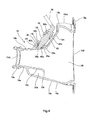
- Fig. 7 is a left side view of an air-intake duct according to Embodiment 2 of the present invention.
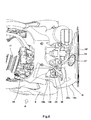
- Fig. 8 is a plan view of the air-intake duct of Fig. 7 .
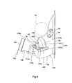
- Fig. 9 is a right side view of major components of the air-intake duct of Fig. 7 .
- Fig. 1 is a left side view of a motorcycle 1 according to Embodiment 1 of the present invention.
- the motorcycle 1 is of a motocross type motorcycle for driving off-road.
- the motorcycle 1 includes a front fork 2 extending substantially vertically with a predetermined caster angle.
- a front wheel 3 which is a drive wheel, is rotatably mounted to a lower portion of the front fork 2.
- a lower portion of a steering shaft 4 is coupled to an upper portion of the front fork 2.
- a bar-type handle 5 is attached to an upper portion of the steering shaft 4.
- the steering shaft 4 is rotatably inserted into a head pipe 7 forming a frame 6. When a driver rotates the handle 5, the front wheel 3 is steered.
- the frame 6 includes a head pipe 7 and a pair of right and left main frames 8 extending rearward from an upper portion of the head pipe 7 such that the main frames 8 are tilted slightly downward.
- An upper portion of a down frame 9 extending downward in a slightly rearward direction is coupled to a lower portion of the head pipe 7.
- a lower frame 10 extends rearward from a lower portion of the down frame 9 such that the lower frame 10 is curved in substantially L-shape, when viewed from a side.
- a rear portion of the main frame 8 is coupled to a rear portion of the lower frame 10 by each of a pair of right and left swing arm brackets 11.
- a swing arm 12 extending substantially in a forward and rearward direction is pivotally mounted at a front portion thereof to the swing arm bracket 11.
- a rear wheel 13 which is a drive wheel is rotatably mounted to a rear portion of the swing arm 12.
- a rear suspension 14 extending substantially vertically is provided between the swing arm 12 and an upper portion of the swing arm bracket 11.
- An engine 15 is mounted in a space defined by the frame 6 and is fastened to respective portions of the frame 6.
- the engine 15 includes a crankcase 15a, a cylinder 15b extending upward from an upper portion of the crankcase 15a, and a transmission 15c extending rearward from a rear portion of the crankcase 15a.
- An output shaft (not shown) of the transmission 15c transmits a driving power to the rear wheel 3 via a chain 16.
- An intake port 15d which opens rearward is formed at a rear portion of the cylinder 15b of the engine 15.
- a throttle device 18 is coupled to the intake port 15d via a pipe-shaped holder 17 extending rearward.
- An air-intake duct 19 is coupled to a rear portion of the throttle device 18 and an air cleaner 20 is coupled to a rear portion of the air-intake duct 19.
- the air cleaner 20 cleans air taken in from outside using an air cleaner element 21 and guides the cleaned air to the air-intake duct 19.
- an opening of the air cleaner element 21 which has a bottomed cylinder shape and is formed by a sponge material faces an inlet 19f (see Fig. 4 ) of the air-intake duct 19 and the air cleaner element 21 closes the inlet 19f (see Fig. 4 ) of the air-intake duct 19.
- An air cleaner holding frame 22 is attached to the air cleaner element 21 and forms side walls of the air cleaner element 21.
- a side cover 23 is disposed behind and continuously with the air cleaner holding frame 22.
- a fuel tank 24 is disposed above the main frames 8.
- a seat 25 straddled by the driver is disposed behind the fuel tank 24.
- a rear fender 26 is positioned behind and in close proximity to the air cleaner element 21 below the seat 25. Air in a space defined by the air clear holding frame 22, the side cover 23, the seat 25 and the rear fender 26 flows through the air cleaner element 21 and then is supplied to the intake port 15d of the engine 15 through the air-intake duct 19, the throttle device 18, and the pipe-shaped holder 17 in this order.
- a twin injector method in which two injectors 27 and 28 are provided, is used. A fuel fed from the fuel tank 24 is injected to two spots in the air-intake passage individually. This makes it possible to reduce an injection time per fuel injection and to set fuel injection timings with large intervals, as compared to a case where fuel injection is performed using a single injector. Therefore, it is possible to set an optimal injection timing under a high engine speed condition.
- Fig. 2 is a left side view of major components, showing the air-intake duct 19 of the motorcycle 1 of Fig, 1 and a region surrounding the air-intake duct 19.
- an air-intake passage connecting the intake port 15d of the engine 15 to the air cleaner 20 is formed by the pipe-shaped holder 17, the throttle device 18 and the air-intake duct 19.
- the pipe-shaped holder 17, the throttle device 18, the air-intake duct 19 and the air cleaner 20 are arranged substantially horizontally in this order in a rearward direction.
- the pipe-shaped holder 17 is a tubular member for coupling the intake port 15d to the throttle device 18.
- the throttle device 18 has a body 30 forming its air-intake passage, and a butterfly throttle valve (not shown) is provided inside the body 30 to control an air-intake amount.
- a downstream injector 27 is attached to a body 30 of the throttle device 18 to inject the fuel to its air-intake passage.
- the downstream injector 27 is attached to an upper portion of the body 30 to extend in a tilted state such that its front end injection port (not shown) faces obliquely forward, and injects a fuel to a region of the air-intake passage which is near and downstream of a throttle valve (not shown).
- a feed tube 32 is coupled to a rear end of the downstream injector 27, and the fuel outflowing from the fuel tank 24 flows through the feed tube 32.
- An air-intake pressure sensor 33 is coupled to the body 30 of the throttle device 18 to detect an air-intake pressure in the air-intake passage.
- a downstream end portion of the air-intake duct 19 is externally fitted to a rear end of the throttle device 18.
- a C-shaped metal band 34 is fitted to the end portion of the air-intake duct 19 and is fastened thereto by a bolt 35.
- An upstream injector 28 is attached to the air-intake duct 19 to inject the fuel to the air-intake passage inside thereof.
- a fuel guide pipe 36 is coupled to a rear end of the upstream injector 28.
- a fuel guided from the fuel tank 24 through the feed tube (not shown) flows into the fuel guide pipe 36.
- a temperature sensor 37 is attached on the air-intake duct 19 to detect a temperature of the air flowing in the air-intake passage.
- Fig. 3 is a perspective view showing the air-intake duct 19 of Fig. 2 , as viewed from leftward and obliquely forward.
- Fig. 4 is a longitudinal sectional view of the air-intake duct 19 of Fig. 3 .
- the air-intake duct 19 includes a tubular wall 19a made of elastomer resin such as rubber which is an elastic material and an injector fastening bracket 40 which is integral with the tubular wall 19a and is made of a stiff material such as metal or resin.
- the tubular wall 19a includes a pipe-shaped portion 19b coupled to the throttle device 18 (see Fig.
- a chamber portion 19c which is provided continuously with an upstream side (rear side) of the pipe-shaped portion 19b in an air flow direction and has a larger inner diameter than the pipe-shaped portion 19b.
- An outlet 19d is formed at a front end portion of the pipe-shaped portion 19b and air flows out to the throttle device 18 (see Fig. 1 ) through the outlet 19d.
- An inlet 19f is formed at a rear end portion of the chamber portion 19c and the air from the air cleaner 20 (see Fig. 1 ) flows into the inlet 19f.
- An inner space connecting the inlet 19f to the outlet 19d is an air-intake passage 39.
- a band mounting annular recess 19e is formed on an outer peripheral surface of a front end portion of the pipe-shaped portion 19b.
- a holding tongue portion 19s protrudes radially outward from a portion of a front end of the pipe-shaped portion 19b.
- An injector attaching portion 19h for attaching the upstream injector 25 protrudes radially outward and upward from an upper portion of the pipe-shaped portion 19b.
- a fuel injection opening section 19i of a substantially cylindrical shape is formed in the injector attaching portion 19h to provide a communication between outside and the air-intake passage 39. The fuel injection opening section 19i communicates with a region of the air-intake passage 39 which is defined by the pipe-shaped portion 19b.
- the fuel injection opening section 19i is tilted such that its lower side (air-intake passage side) faces obliquely forward.
- the fuel injection opening section 19i has an upper large-diameter portion 19j in an upper region (outer region) such that the upper large-diameter portion 19j has a larger diameter than a lower region (air-intake passage side region).
- the upstream injector 28 is attached to the injector attaching portion 19h of the air-intake duct 19. Therefore, the injected fuel is suppressed from getting stagnant as compared to a case where the upstream injector 28 is attached to the air cleaner 20.
- the fuel injection opening section 19i is formed at the pipe-shaped portion 19b which is downstream of the chamber portion 19c and has a smaller inner diameter than the chamber portion 19c, the fuel injected from the upstream injector 28 to the air-intake passage 39 through the fuel injection opening section 19i is sufficiently suppressed from getting stagnant therein. As a result, an error of the amount of the fuel fed to the engine 15 is lessened.
- the upstream injector 28 is attached to the air-intake duct 19, the spot where the temperature of the air-fuel mixture decreases due to vaporization heat of the fuel injected by the upstream injector 28 is located upstream relative to the throttle device 18, thereby resulting in an improved filling efficiency of the air-fuel mixture to the engine 15.
- reduction of the error of the amount of fuel fed to the engine 15 and improvement of the filling efficiency of the air-fuel mixture are both achieved suitably.
- a portion of the injector attaching portion 19h is continuous with an upper outer surface of the chamber portion 19c. This allows the injector attaching portion 19h to serve as a reinforcement rib. Therefore, it is possible to prevent the chamber portion 19c from depressing inward even when a negative pressure is suddenly generated in the chamber portion 19c, for example, when the engine is accelerated. As a result, a high air-intake efficiency is maintained and an acceleration response is improved.
- the chamber portion 19c has an unsymmetric shape in an upward and downward direction and in a rightward and leftward direction and has a diameter substantially decreasing in a direction from the inlet 19f toward the pipe-shaped portion 19b.
- the pipe-shaped portion 19b is positioned leftward relative to a center of the chamber portion 19c.
- a flange portion 19g is provided at a rear end of the chamber portion 19c and coupled to the air cleaner 20 (see Fig. 1 ).
- the chamber portion 19c has an upper portion 19k (first portion) which is close to the injector attaching portion 19h and a lower portion 19p (second portion) which is at an opposite side of the upper portion 19k in a circumferential direction.
- the lower portion 19p is longer than the upper portion 19k in the air flow direction.
- the lower portion 19p allows the chamber portion 19c to sufficiently ensure its volume, although a space for the upper portion 19k of the chamber portion 19c is constrained by the upstream injector 28 disposed in the vicinity of the upper portion 19k. As a result, a high air-intake efficiency is maintained while disposing the upstream injector 28 flexibly.
- the upper portion 19k of the chamber portion 19c has a large-diameter portion 19m which is located at the flange portion 19g side and is provided with a temperature sensor attaching portion 19t and a small-diameter portion 19n having a diameter decreasing in a direction from the large-diameter portion 19m toward the pipe-shaped portion 19b.
- the lower portion 19p of the chamber portion 19c covers an outer surface side of a lower rear portion 19q of the pipe-shaped portion 19b with a gap 39a provided therebetween.
- a front end portion of the lower portion 19p is coupled to an intermediate portion of the pipe-shaped portion 19b in the flow direction.
- the lower rear portion 19q of the pipe-shaped portion 19b which is covered with the lower portion 19p has an end portion 19r protruding into an inner space of the chamber portion 19c and having a funnel shape in which its diameter increases toward a tip end.
- the injector fastening bracket 40 is formed by, for example, press-forming of a metal plate.
- the injector fastening bracket 40 is integral with the tubular wall 19a by insert molding when forming the tubular wall 19a.
- the injector fastening bracket 40 includes a first injector support portion 40 disposed at the upper large-diameter portion 19j of the fuel injection opening section 19i of the injector attaching portion 19h and surrounding the front end portion 28a of the upstream injector 28, and a second injector support portion 40b disposed at an outer surface of the small-diameter portion 19n of the upper portion 19k of the chamber portion 19c.
- the first injector support portion 40a includes a tubular side wall portion 40e continuous with the second injector support portion 40b, and an annular bottom portion 40c which is provided continuously with a lower end of the tubular side wall 40e and has a center hole 40d.
- the front end portion 28a of the upstream injector 28 is disposed in the fuel injection opening section 19i such that it is inserted into the center hole 40d.
- An annular seal member 41 is provided between an outer peripheral surface of the upstream injector 28 and the tubular side wall 40e of the first injector support portion 40a in an air-tight manner.
- a fuel guide pipe 36 is coupled to a rear end portion 28b of the upstream injector 28.
- a connector 28c for connecting electric wires is provided in a location rightward relative to the fuel guide pipe 36 (close to the center of the vehicle body).
- a stay 42 is provided integrally with the fuel guide pipe 36.
- the stay 42 is fastened to the second injector support portion 40b by a fastener member 43 (e.g., threaded member, screw, etc).
- the stay 42 and the fastening member 43 are a fastening member 44 for supporting the upstream injector 28 and fastening it to the second injector support portion 40b.
- the upstream injector 28 is disposed to be tilted along the outer surface of the chamber portion 19c such that the front end portion 28a faces obliquely forward in the fuel injection opening section 19i.
- the injector fastening bracket 40 serves to reinforce the chamber portion 19c, it is possible to prevent the chamber portion 19c from depressing inward even when a negative pressure is suddenly generated in the chamber portion 19c, for example, when the engine is accelerated. As a result, a high air-intake efficiency is maintained and an acceleration response is improved. Even if the chamber portion 19c is depressed to a certain degree by a high negative pressure generated in the chamber portion 19c, for example, when the engine is accelerated, it is possible to prevent the upstream injector 28 from disengaging from the injector attaching portion 19h because a positional relationship between the first injector support portion 40a and the second injector support portion 40b is determined by the injector fastening bracket 40.
- Fig. 5 is a left side view of major components showing a positional relationship between the air-intake duct 19 and the main frame 8 in the motorcycle 1 of Fig. 1 .
- Fig. 5 is a side view when viewed in a direction (direction in the direction of along A in Fig. 6 ) perpendicular to a passage axis of the pipe-shaped portion 19b of the air-intake duct 19.
- the main frame 8 is disposed to extend from left and obliquely upper to right and obliquely lower, at a left side of the air-intake duct 19.
- the main frame 8 substantially passes through a space leftward relative to and beside the pipe-shape portion 19b of the air-intake duct 19.
- a head portion 35a of a bolt 35 for fastening the metal band 34 used for fastening the air-intake duct 19 to the throttle device 18 is not covered with the main frame 8.
- the main frame 8 is not disposed above an axis of the bolt 35 to allow a tool to easily access the head portion 35a of the bolt 35.
- Fig. 6 is a plan view of the air-intake duct 19 of the motorcycle 1 of Fig, 1 and the region surrounding the air-intake duct 19.
- the air-intake duct 19 is disposed to pass through a space leftward relative to the rear suspension 14 positioned at a center in a lateral direction of the vehicle body.
- the inlet 19f of the air-intake duct 19 is positioned behind the rear suspension 14 and extends from right and obliquely rear to left and obliquely rear of the rear suspension 14.
- a right side surface of the chamber portion 19c of the air-intake duct 19 is curved along the rear suspension 14.
- the passage axis of the pipe-shaped portion 19b of the air-intake duct 19 is slightly tilted rightward and obliquely forward such that a front end of the pipe-shaped portion 19b is closer to a center in the lateral direction of the vehicle body.
- Such a tilted arrangement can avoid the head portion 35a of the bolt 35 (see Fig. 5 ) for fastening the metal-made band 34 (see Fig. 5 ) from being hidden by the main frame 8, when viewed from a side.
- the fuel guide pipe 36 coupled to the upstream injector 28 is disposed outward (leftward) relative to the connector 28c of the upstream injector 28 in the lateral direction of the vehicle body.
- the fuel guide pipe 36 is located outward relative to an electric wire (not shown) connected to the connector 28c, and therefore, maintenance of the fuel guide pipe 36 is easily performed.
- the electric wire (not shown) connected to the connector 28c is disposed at a center of the vehicle body, it is possible to prevent the electric wire (not shown) from contacting an obstacle and being disconnected, during driving off-road
- Fig. 7 is a left side view of an air-intake duct 119 according to Embodiment 2 of the present invention.
- Fig. 8 is a plan view of the air-intake duct 119 of Fig. 7 .
- Fig. 9 is a right side view of major constituents of the air-intake duct 119 of Fig. 7 .
- the same constituents as those in Embodiment 1 are designated by the same reference numerals and will not be described repetitively.
- a tubular wall 119a of the air-intake duct 119 of this embodiment has a structure for protecting the injector 28 from mud and the like splashing during driving off-road.
- An upper portion 119k of the chamber portion 119c of the air-intake duct 119 has a large-diameter portion 119m which is located the flange portion 19g side and is provided with the temperature sensor attaching portion 19t and a small-diameter portion 119n having a diameter decreased from the large-diameter portion 119m toward the pipe-shaped portion 19b.
- the small-diameter portion 119n has a recess 120 (see Fig. 8 ) which is depressed in a rearward direction when viewed from above.
- the injector 28 (see Fig. 9 ) attached on the injector attaching portion 19h is disposed in the recess 120.
- a wall surface of the recess 120 serves as a cover for protecting the injector 28 from mud and the like splashing during driving off-road.
- the small-diameter portion 119n includes a right small-diameter portion 119n1 positioned at a right side of the injector 28 to vertically extend at the right side of the injector attaching portion 19h and a left small-diameter portion 119n2 positioned at a left side of the injector 28 to vertically extend at the left side of the injector attaching portion 19h.
- the right small-diameter portion 119n1 and the left small-diameter portion 119n2 are tilted to form a substantially V-shape when viewed from above.
- An injector fastening bracket 140 is formed by insert molding to be integral with the tubular wall 119a and the chamber portion 119c when forming the tubular wall 119a and the chamber portion 119c.
- the injector fastening bracket 140 includes a first injector support portion 140a which is disposed in the fuel injection opening section 19i of the injector attaching portion 19h so as to surround a front end portion of the injector 28, a second injector support portion 140b disposed on an outer surface of the right small-diameter portion 119n1 continuously with the first injector support portion 140a, and a third injector support portion 140c disposed on an outer surface of the left small-diameter portion 119n2 continuously with the second injector support portion 140b.
- a plate-shaped cover portion 119u is provided to protrude from a front end portion of the left small-diameter portion 119n2 and a portion of the injector attaching portion 19h which is leftward relative to the fuel injection opening section 19i.
- the cover portion 119u is formed integrally with the tubular wall 119a.
- the cover portion 119u covers a left side to a front side of the injector 28 attached to the injector attaching portion 19h.
- the cover portion 119u is disposed to cover the injector 28 from an opposite side of the rear suspension 14 with respect to the injector attaching portion 19h.
- the cover portion 119u serves to sufficiently protect the injector 28 from mud and the like splashing outside the vehicle body, during driving off-road.
- a front end portion 119u1 of the cover portion 119u is curved to cover the injector 28 from forward when viewed from above.
- the front end portion 119u1 of the cover portion 119u is positioned so as to cover the connector 28c of the injector 28.
- the cover portion 119u protrudes upward such that the cover portion 119u is higher than the left small-diameter portion 119n2 (see Figs. 7 and 9 ).
- the other constituents are identical to those of Embodiment 1 described above and will not be described repetitively.
- the present invention is applied to the motorcycle, the present invention is applicable to vehicles which are driven by an engine driving power.
- the vehicles include, for example, a four-wheeled automobile, and straddle-type vehicles including seats which are straddled by a driver.
- the straddle-type vehicles include the motorcycle, an ATV (all terrain vehicle), and small personal watercraft (PWC).
Landscapes
- Engineering & Computer Science (AREA)
- Chemical & Material Sciences (AREA)
- Combustion & Propulsion (AREA)
- Mechanical Engineering (AREA)
- General Engineering & Computer Science (AREA)
- Fuel-Injection Apparatus (AREA)
- Control Of Throttle Valves Provided In The Intake System Or In The Exhaust System (AREA)
Abstract
Description
- This application claims priority to and the benefit of Japanese Patent Application No.
2009-299156 filed on December 29, 2009 - The present invention relates to an air-intake duct for a vehicle for guiding air from an air cleaner to a throttle device, and the vehicle.
- In a known air-intake system of a motorcycle, air cleaned by an air cleaner is guided to a throttle device via an air-intake duct and then to an engine after its air-intake amount is controlled by a throttle valve. Japanese Laid-Open Patent Application Publication No.
2006-90298 2008-207790 - A suction pressure generated by a piston movement of an engine is transferred to an air cleaner box. Since the suction pressure is blocked when an intake valve of an intake port of the engine is closed, a pulsation is generated in air flowing from the air cleaner box toward the engine. Therefore, in the motorcycle of Patent literature 1, a part of a fuel injected from the upstream injector to an internal volume space of the air cleaner box is not guided toward the engine but gets stagnant inside the air cleaner box, causing an error in an amount of the fuel to be fed to the engine.
- In contrast, in the motorcycle disclosed in
patent literature 2, the upstream injector is attached to the throttle device forming the air-intake passage with a small inner diameter. Therefore, even if a pulsation is generated in the air in the air-intake passage of the throttle device, the fuel injected from the upstream injector does not get stagnant, and thus, an error of the amount of fuel fed to the engine is reduced. - However, since the upstream injector is attached to the throttle device, a spot where a temperature of an air-fuel mixture decreases due to a vaporization heat of the fuel injected by the upstream injector is located at a downstream side relative to a spot in the example disclosed in patent literature 1. Since a volume of the air-fuel mixture guided to the engine decreases (its density increases) with a decrease in the temperature of the air-fuel mixture, a filling efficiency of the air-fuel mixture to the engine improves and a driving power increases. When the spot where the temperature of the air-fuel-mixture decreases is located the downstream side, it is difficult to improve the filling efficiency of the air-fuel mixture. The length of the throttle device may possibly be increased to position the upstream injector at an upstream side. However, if a metal-made throttle device is increased in size, its weight increases undesirably. In addition, if the length of the throttle device increases, the position of the air cleaner box must be changed correspondingly. It is difficult to change the position of the air cleaner box in a limited component arrangement space of the motorcycle.
- An object of the present invention is to suitably achieve reduction of an error of an amount of a fuel fed to an engine and improvement of a filling efficiency of an air-fuel mixture.
- An air-intake duct for a vehicle of the present invention, which couples a throttle device for controlling an air-intake amount of an engine to an air cleaner for cleaning air guided to the throttle device; comprises a tubular wall forming an inlet through which air from the air cleaner flows into the air-intake duct; an outlet through which the air flows out to the throttle device; and an air-intake passage connecting the inlet to the outlet; the tubular wall including an injector attaching portion to which an injector for injecting a fuel to the air-intake passage is attached, and the injector attaching portion having a fuel injection opening section communicating with the air-intake passage.
- In accordance with this configuration, since the injector is attached to the air-intake duct, the injected fuel is less likely to get stagnant and an error of an amount of the fuel fed to the engine is reduced, as compared to a case where the injector is attached to the air cleaner. Since the injector is attached to the air-intake duct, the spot where the temperature of the air-fuel mixture decreases due to vaporization heat of the fuel injected by the injector is located upstream of the throttle device. This results in an improved filling efficiency of the air-fuel mixture to the engine. As a result, reduction of the error of the amount of fuel fed to the engine and improvement of the filling efficiency of the air-fuel mixture are both achieved suitably.
- The tubular wall may include a pipe-shaped portion connected to the throttle device; and a chamber portion which is provided upstream of the pipe-shaped portion in an air flow direction and has a larger inner diameter larger than the pipe-shaped portion. The fuel injection opening section may be provided in the pipe-shaped portion.
- In accordance with this configuration, in the air-intake duct having the pipe-shaped portion and the chamber portion, since the fuel injection opening section is formed in the pipe-shaped portion which is downstream of the chamber portion and has a smaller inner diameter than the chamber portion, the fuel injected from the injector to the air-intake passage through the fuel injection opening section is less likely to get stagnant, and an error of the fuel fed to the engine can be further reduced.
- The tubular wall may be formed of an elastic material; and the injector attaching portion may protrude radially outward from the pipe-shaped portion and may be continuous with an outer surface of the chamber portion.
- In accordance with this configuration, since the injector attaching portion serves as a reinforcement rib, it is possible to prevent the chamber portion from depressing inward even when a negative pressure is suddenly generated in the chamber, for example, when the engine is accelerated. As a result, a high air-intake efficiency is maintained and an acceleration response is improved.
- The chamber portion may include a first portion which is close to the injector attaching portion in a circumferential position and a second portion which is at an opposite side of the first portion in a circumferential position. The second portion may be longer than the first portion in the air flow direction.
- In accordance with this configuration, since the second portion of the chamber portion is longer than the first portion of the chamber portion in the air flow direction, a sufficient volume of the chamber portion can be ensured, even though the first portion of the chamber portion has a size for allowing for a space in which the injector is disposed in the vicinity of the first portion Therefore, a high air-intake efficiency can be maintained while maintaining flexibility with which the injector is disposed.
- The second portion may cover the pipe-shaped portion such that there is a gap between the second portion and an outer surface of an upstream portion of the pipe-shaped portion, and an end portion of the second portion which is located at the pipe-shaped portion side may be connected to an intermediate portion of the pipe-shaped portion in the air flow direction.
- In accordance with this configuration, it is possible to avoid the length of the pipe-shaped portion from being reduced although the length of the second portion is made longer than that of the first portion in the air flow direction. Therefore, because of the small-diameter pipe-shaped portion, generation of a disturbed flow can be sufficiently suppressed and a high air-intake efficiency can be maintained.
- An end portion of a portion of the pipe-shaped portion which is covered with the second portion may have a diameter increased toward a tip end, the end portion protruding into an inner space of the chamber portion.
- In accordance with this configuration, air present in the chamber portion is guided smoothly to the pipe-shaped portion, and thus an air-intake resistance can be reduced.
- The air-intake duct may further comprise an injector fastening bracket provided at the chamber portion, the tubular wall may be formed of an elastic material, and the injector fastening bracket may be formed of a stiff material.
- In accordance with this configuration, since the injector fastening bracket serves to reinforce the chamber portion, it is possible to prevent the chamber portion from depressing inward even when a negative pressure is suddenly generated in the chamber portion, for example, when the engine is accelerated. Therefore, a high air-intake efficiency can be maintained and an acceleration response can be improved.
- The injector fastening bracket may include a first injector support portion disposed in the fuel injection opening section such that the first injector support portion surrounds a front end portion of the injector and a second injector support portion provided at the chamber portion and attached with a fastening member for supporting the injector.
- In accordance with this configuration, even if the chamber portion is depressed to a certain degree by a negative pressure suddenly generated in the chamber portion, for example, when the engine is accelerated, it is possible to prevent the injector from disengaging from the injector attaching portion because a positional relationship between the first injector support portion and the second injector support portion is determined by the injector fastening bracket.
- The tubular wall may have a recess in which the injector attached to the injector attaching portion is disposed, when viewed from above.
- In accordance with this configuration, the wall surface of the recess can protect the injector attached to the injector attaching portion from mud and the like splashing.
- The tubular wall may be provided with a cover portion for covering the injector attached to the injector attaching portion.
- In accordance with this configuration, the cover portion can protect the injector attached to the injector attaching portion from mud and the like splashing.
- The cover portion may be positioned outward relative to the injector when viewed from a vehicle body of the vehicle, and may be integral with the tubular wall such that the cover portion covers the injector from a side.
- In accordance with this configuration, the cover portion covers the injector from outside when viewed from the body, more effectively. Since the cover portion is integral with the tubular wall, the number of components does not increase, and the air-intake duct can be handled easily.
- The above and further objects and features of the invention will more fully be apparent from the following detailed description with accompanying drawings.
-
Fig. 1 is a left side view showing a motorcycle according to Embodiment 1 of the present invention. -
Fig. 2 is a left side view of major components, showing an air-intake duct of the motorcycle ofFig, 1 and a region surrounding the air-intake duct. -
Fig. 3 is a perspective view showing the air-intake duct ofFig. 2 , when viewed from leftward and obliquely forward. -
Fig. 4 is a longitudinal sectional view of the air-intake duct ofFig. 3 . -
Fig. 5 is a left side view of major components showing a positional relationship between the air-intake duct and a main frame in the motorcycle ofFig. 1 . -
Fig. 6 is a plan view showing the air-intake duct of the motorcycle ofFig, 1 and the region surrounding the air-intake duct. -
Fig. 7 is a left side view of an air-intake duct according toEmbodiment 2 of the present invention. -
Fig. 8 is a plan view of the air-intake duct ofFig. 7 . -
Fig. 9 is a right side view of major components of the air-intake duct ofFig. 7 . - Hereinafter, embodiments of the present invention will be described with reference to the drawings. The stated directions are referenced from the perspective of a driver straddling the motorcycle.
- (Embodiment 1)
-
Fig. 1 is a left side view of a motorcycle 1 according to Embodiment 1 of the present invention. As shown inFig. 1 , the motorcycle 1 is of a motocross type motorcycle for driving off-road. The motorcycle 1 includes afront fork 2 extending substantially vertically with a predetermined caster angle. Afront wheel 3 which is a drive wheel, is rotatably mounted to a lower portion of thefront fork 2. A lower portion of a steering shaft 4 is coupled to an upper portion of thefront fork 2. A bar-type handle 5 is attached to an upper portion of the steering shaft 4. The steering shaft 4 is rotatably inserted into ahead pipe 7 forming aframe 6. When a driver rotates thehandle 5, thefront wheel 3 is steered. - The
frame 6 includes ahead pipe 7 and a pair of right and leftmain frames 8 extending rearward from an upper portion of thehead pipe 7 such that themain frames 8 are tilted slightly downward. An upper portion of adown frame 9 extending downward in a slightly rearward direction is coupled to a lower portion of thehead pipe 7. Alower frame 10 extends rearward from a lower portion of thedown frame 9 such that thelower frame 10 is curved in substantially L-shape, when viewed from a side. A rear portion of themain frame 8 is coupled to a rear portion of thelower frame 10 by each of a pair of right and leftswing arm brackets 11. Aswing arm 12 extending substantially in a forward and rearward direction is pivotally mounted at a front portion thereof to theswing arm bracket 11. Arear wheel 13 which is a drive wheel is rotatably mounted to a rear portion of theswing arm 12. Arear suspension 14 extending substantially vertically is provided between theswing arm 12 and an upper portion of theswing arm bracket 11. - An
engine 15 is mounted in a space defined by theframe 6 and is fastened to respective portions of theframe 6. Theengine 15 includes acrankcase 15a, acylinder 15b extending upward from an upper portion of thecrankcase 15a, and atransmission 15c extending rearward from a rear portion of thecrankcase 15a. An output shaft (not shown) of thetransmission 15c transmits a driving power to therear wheel 3 via achain 16. Anintake port 15d which opens rearward is formed at a rear portion of thecylinder 15b of theengine 15. Athrottle device 18 is coupled to theintake port 15d via a pipe-shapedholder 17 extending rearward. An air-intake duct 19 is coupled to a rear portion of thethrottle device 18 and anair cleaner 20 is coupled to a rear portion of the air-intake duct 19. - The
air cleaner 20 cleans air taken in from outside using an aircleaner element 21 and guides the cleaned air to the air-intake duct 19. To be specific, an opening of theair cleaner element 21 which has a bottomed cylinder shape and is formed by a sponge material faces aninlet 19f (seeFig. 4 ) of the air-intake duct 19 and theair cleaner element 21 closes theinlet 19f (seeFig. 4 ) of the air-intake duct 19. An aircleaner holding frame 22 is attached to theair cleaner element 21 and forms side walls of theair cleaner element 21. Aside cover 23 is disposed behind and continuously with the aircleaner holding frame 22. - A
fuel tank 24 is disposed above themain frames 8. Aseat 25 straddled by the driver is disposed behind thefuel tank 24. Arear fender 26 is positioned behind and in close proximity to theair cleaner element 21 below theseat 25. Air in a space defined by the airclear holding frame 22, theside cover 23, theseat 25 and therear fender 26 flows through theair cleaner element 21 and then is supplied to theintake port 15d of theengine 15 through the air-intake duct 19, thethrottle device 18, and the pipe-shapedholder 17 in this order. As a fuel feeding method of the motorcycle 1, a twin injector method in which twoinjectors fuel tank 24 is injected to two spots in the air-intake passage individually. This makes it possible to reduce an injection time per fuel injection and to set fuel injection timings with large intervals, as compared to a case where fuel injection is performed using a single injector. Therefore, it is possible to set an optimal injection timing under a high engine speed condition. -
Fig. 2 is a left side view of major components, showing the air-intake duct 19 of the motorcycle 1 ofFig, 1 and a region surrounding the air-intake duct 19. As shown inFig. 2 , an air-intake passage connecting theintake port 15d of theengine 15 to the air cleaner 20 (seeFig. 1 ) is formed by the pipe-shapedholder 17, thethrottle device 18 and the air-intake duct 19. The pipe-shapedholder 17, thethrottle device 18, the air-intake duct 19 and theair cleaner 20 are arranged substantially horizontally in this order in a rearward direction. The pipe-shapedholder 17 is a tubular member for coupling theintake port 15d to thethrottle device 18. Thethrottle device 18 has abody 30 forming its air-intake passage, and a butterfly throttle valve (not shown) is provided inside thebody 30 to control an air-intake amount. - A
downstream injector 27 is attached to abody 30 of thethrottle device 18 to inject the fuel to its air-intake passage. Thedownstream injector 27 is attached to an upper portion of thebody 30 to extend in a tilted state such that its front end injection port (not shown) faces obliquely forward, and injects a fuel to a region of the air-intake passage which is near and downstream of a throttle valve (not shown). Afeed tube 32 is coupled to a rear end of thedownstream injector 27, and the fuel outflowing from thefuel tank 24 flows through thefeed tube 32. An air-intake pressure sensor 33 is coupled to thebody 30 of thethrottle device 18 to detect an air-intake pressure in the air-intake passage. - A downstream end portion of the air-
intake duct 19 is externally fitted to a rear end of thethrottle device 18. In this state, a C-shapedmetal band 34 is fitted to the end portion of the air-intake duct 19 and is fastened thereto by abolt 35. Anupstream injector 28 is attached to the air-intake duct 19 to inject the fuel to the air-intake passage inside thereof. Afuel guide pipe 36 is coupled to a rear end of theupstream injector 28. A fuel guided from thefuel tank 24 through the feed tube (not shown) flows into thefuel guide pipe 36. Atemperature sensor 37 is attached on the air-intake duct 19 to detect a temperature of the air flowing in the air-intake passage. -
Fig. 3 is a perspective view showing the air-intake duct 19 ofFig. 2 , as viewed from leftward and obliquely forward.Fig. 4 is a longitudinal sectional view of the air-intake duct 19 ofFig. 3 . As shown inFigs. 3 and4 , the air-intake duct 19 includes atubular wall 19a made of elastomer resin such as rubber which is an elastic material and aninjector fastening bracket 40 which is integral with thetubular wall 19a and is made of a stiff material such as metal or resin. Thetubular wall 19a includes a pipe-shapedportion 19b coupled to the throttle device 18 (seeFig. 1 ) and achamber portion 19c which is provided continuously with an upstream side (rear side) of the pipe-shapedportion 19b in an air flow direction and has a larger inner diameter than the pipe-shapedportion 19b. Anoutlet 19d is formed at a front end portion of the pipe-shapedportion 19b and air flows out to the throttle device 18 (seeFig. 1 ) through theoutlet 19d. Aninlet 19f is formed at a rear end portion of thechamber portion 19c and the air from the air cleaner 20 (seeFig. 1 ) flows into theinlet 19f. An inner space connecting theinlet 19f to theoutlet 19d is an air-intake passage 39. - A band mounting
annular recess 19e is formed on an outer peripheral surface of a front end portion of the pipe-shapedportion 19b. A holdingtongue portion 19s protrudes radially outward from a portion of a front end of the pipe-shapedportion 19b. Aninjector attaching portion 19h for attaching theupstream injector 25 protrudes radially outward and upward from an upper portion of the pipe-shapedportion 19b. A fuelinjection opening section 19i of a substantially cylindrical shape is formed in theinjector attaching portion 19h to provide a communication between outside and the air-intake passage 39. The fuelinjection opening section 19i communicates with a region of the air-intake passage 39 which is defined by the pipe-shapedportion 19b. The fuelinjection opening section 19i is tilted such that its lower side (air-intake passage side) faces obliquely forward. The fuelinjection opening section 19i has an upper large-diameter portion 19j in an upper region (outer region) such that the upper large-diameter portion 19j has a larger diameter than a lower region (air-intake passage side region). - As described above, the
upstream injector 28 is attached to theinjector attaching portion 19h of the air-intake duct 19. Therefore, the injected fuel is suppressed from getting stagnant as compared to a case where theupstream injector 28 is attached to theair cleaner 20. In addition, since the fuelinjection opening section 19i is formed at the pipe-shapedportion 19b which is downstream of thechamber portion 19c and has a smaller inner diameter than thechamber portion 19c, the fuel injected from theupstream injector 28 to the air-intake passage 39 through the fuelinjection opening section 19i is sufficiently suppressed from getting stagnant therein. As a result, an error of the amount of the fuel fed to theengine 15 is lessened. In addition, since theupstream injector 28 is attached to the air-intake duct 19, the spot where the temperature of the air-fuel mixture decreases due to vaporization heat of the fuel injected by theupstream injector 28 is located upstream relative to thethrottle device 18, thereby resulting in an improved filling efficiency of the air-fuel mixture to theengine 15. As a result, reduction of the error of the amount of fuel fed to theengine 15 and improvement of the filling efficiency of the air-fuel mixture are both achieved suitably. - A portion of the
injector attaching portion 19h is continuous with an upper outer surface of thechamber portion 19c. This allows theinjector attaching portion 19h to serve as a reinforcement rib. Therefore, it is possible to prevent thechamber portion 19c from depressing inward even when a negative pressure is suddenly generated in thechamber portion 19c, for example, when the engine is accelerated. As a result, a high air-intake efficiency is maintained and an acceleration response is improved. - The
chamber portion 19c has an unsymmetric shape in an upward and downward direction and in a rightward and leftward direction and has a diameter substantially decreasing in a direction from theinlet 19f toward the pipe-shapedportion 19b. To be specific, the pipe-shapedportion 19b is positioned leftward relative to a center of thechamber portion 19c. Aflange portion 19g is provided at a rear end of thechamber portion 19c and coupled to the air cleaner 20 (seeFig. 1 ). Thechamber portion 19c has anupper portion 19k (first portion) which is close to theinjector attaching portion 19h and alower portion 19p (second portion) which is at an opposite side of theupper portion 19k in a circumferential direction. Thelower portion 19p is longer than theupper portion 19k in the air flow direction. Thelower portion 19p allows thechamber portion 19c to sufficiently ensure its volume, although a space for theupper portion 19k of thechamber portion 19c is constrained by theupstream injector 28 disposed in the vicinity of theupper portion 19k. As a result, a high air-intake efficiency is maintained while disposing theupstream injector 28 flexibly. - The
upper portion 19k of thechamber portion 19c has a large-diameter portion 19m which is located at theflange portion 19g side and is provided with a temperaturesensor attaching portion 19t and a small-diameter portion 19n having a diameter decreasing in a direction from the large-diameter portion 19m toward the pipe-shapedportion 19b. Thelower portion 19p of thechamber portion 19c covers an outer surface side of a lower rear portion 19q of the pipe-shapedportion 19b with agap 39a provided therebetween. A front end portion of thelower portion 19p is coupled to an intermediate portion of the pipe-shapedportion 19b in the flow direction. This makes it possible to prevent the length of the pipe-shapedportion 19b from being reduced while making thelower portion 19p of thechamber portion 19c longer than theupper portion 19k in the air flow direction. With the pipe-shapedportion 19b with a smaller diameter, generation of a disordered flow can be sufficiently suppressed, and as a result, a high air-intake efficiency is maintained. - The lower rear portion 19q of the pipe-shaped
portion 19b which is covered with thelower portion 19p has anend portion 19r protruding into an inner space of thechamber portion 19c and having a funnel shape in which its diameter increases toward a tip end. With this structure, the air present in thechamber portion 19c is guided smoothly to the pipe-shapedportion 19b, and thus, an air-intake resistance in the interior of the air-intake duct 19 is reduced. - The
injector fastening bracket 40 is formed by, for example, press-forming of a metal plate. Theinjector fastening bracket 40 is integral with thetubular wall 19a by insert molding when forming thetubular wall 19a. Theinjector fastening bracket 40 includes a firstinjector support portion 40 disposed at the upper large-diameter portion 19j of the fuelinjection opening section 19i of theinjector attaching portion 19h and surrounding thefront end portion 28a of theupstream injector 28, and a secondinjector support portion 40b disposed at an outer surface of the small-diameter portion 19n of theupper portion 19k of thechamber portion 19c. - The first
injector support portion 40a includes a tubularside wall portion 40e continuous with the secondinjector support portion 40b, and anannular bottom portion 40c which is provided continuously with a lower end of thetubular side wall 40e and has acenter hole 40d. Thefront end portion 28a of theupstream injector 28 is disposed in the fuelinjection opening section 19i such that it is inserted into thecenter hole 40d. Anannular seal member 41 is provided between an outer peripheral surface of theupstream injector 28 and thetubular side wall 40e of the firstinjector support portion 40a in an air-tight manner. - A
fuel guide pipe 36 is coupled to arear end portion 28b of theupstream injector 28. Aconnector 28c for connecting electric wires is provided in a location rightward relative to the fuel guide pipe 36 (close to the center of the vehicle body). Astay 42 is provided integrally with thefuel guide pipe 36. Thestay 42 is fastened to the secondinjector support portion 40b by a fastener member 43 (e.g., threaded member, screw, etc). In other words, thestay 42 and thefastening member 43 are a fasteningmember 44 for supporting theupstream injector 28 and fastening it to the secondinjector support portion 40b. In this state, theupstream injector 28 is disposed to be tilted along the outer surface of thechamber portion 19c such that thefront end portion 28a faces obliquely forward in the fuelinjection opening section 19i. - In such a configuration, since the
injector fastening bracket 40 serves to reinforce thechamber portion 19c, it is possible to prevent thechamber portion 19c from depressing inward even when a negative pressure is suddenly generated in thechamber portion 19c, for example, when the engine is accelerated. As a result, a high air-intake efficiency is maintained and an acceleration response is improved. Even if thechamber portion 19c is depressed to a certain degree by a high negative pressure generated in thechamber portion 19c, for example, when the engine is accelerated, it is possible to prevent theupstream injector 28 from disengaging from theinjector attaching portion 19h because a positional relationship between the firstinjector support portion 40a and the secondinjector support portion 40b is determined by theinjector fastening bracket 40. -
Fig. 5 is a left side view of major components showing a positional relationship between the air-intake duct 19 and themain frame 8 in the motorcycle 1 ofFig. 1 .Fig. 5 is a side view when viewed in a direction (direction in the direction of along A inFig. 6 ) perpendicular to a passage axis of the pipe-shapedportion 19b of the air-intake duct 19. As shown inFig. 5 , themain frame 8 is disposed to extend from left and obliquely upper to right and obliquely lower, at a left side of the air-intake duct 19. Themain frame 8 substantially passes through a space leftward relative to and beside the pipe-shape portion 19b of the air-intake duct 19. However, ahead portion 35a of abolt 35 for fastening themetal band 34 used for fastening the air-intake duct 19 to thethrottle device 18 is not covered with themain frame 8. In other words, themain frame 8 is not disposed above an axis of thebolt 35 to allow a tool to easily access thehead portion 35a of thebolt 35. -
Fig. 6 is a plan view of the air-intake duct 19 of the motorcycle 1 ofFig, 1 and the region surrounding the air-intake duct 19. As shown inFig. 6 , the air-intake duct 19 is disposed to pass through a space leftward relative to therear suspension 14 positioned at a center in a lateral direction of the vehicle body. Theinlet 19f of the air-intake duct 19 is positioned behind therear suspension 14 and extends from right and obliquely rear to left and obliquely rear of therear suspension 14. A right side surface of thechamber portion 19c of the air-intake duct 19 is curved along therear suspension 14. - The passage axis of the pipe-shaped
portion 19b of the air-intake duct 19 is slightly tilted rightward and obliquely forward such that a front end of the pipe-shapedportion 19b is closer to a center in the lateral direction of the vehicle body. Such a tilted arrangement can avoid thehead portion 35a of the bolt 35 (seeFig. 5 ) for fastening the metal-made band 34 (seeFig. 5 ) from being hidden by themain frame 8, when viewed from a side. - The
fuel guide pipe 36 coupled to theupstream injector 28 is disposed outward (leftward) relative to theconnector 28c of theupstream injector 28 in the lateral direction of the vehicle body. In this structure, thefuel guide pipe 36 is located outward relative to an electric wire (not shown) connected to theconnector 28c, and therefore, maintenance of thefuel guide pipe 36 is easily performed. In addition, since the electric wire (not shown) connected to theconnector 28c is disposed at a center of the vehicle body, it is possible to prevent the electric wire (not shown) from contacting an obstacle and being disconnected, during driving off-road - (Embodiment 2)
-
Fig. 7 is a left side view of an air-intake duct 119 according toEmbodiment 2 of the present invention.Fig. 8 is a plan view of the air-intake duct 119 ofFig. 7 .Fig. 9 is a right side view of major constituents of the air-intake duct 119 ofFig. 7 . Hereinafter, the same constituents as those in Embodiment 1 are designated by the same reference numerals and will not be described repetitively. As shown inFigs. 7 ∼ 9 , atubular wall 119a of the air-intake duct 119 of this embodiment has a structure for protecting theinjector 28 from mud and the like splashing during driving off-road. Anupper portion 119k of thechamber portion 119c of the air-intake duct 119 has a large-diameter portion 119m which is located theflange portion 19g side and is provided with the temperaturesensor attaching portion 19t and a small-diameter portion 119n having a diameter decreased from the large-diameter portion 119m toward the pipe-shapedportion 19b. - The small-
diameter portion 119n has a recess 120 (seeFig. 8 ) which is depressed in a rearward direction when viewed from above. In therecess 120, the injector 28 (seeFig. 9 ) attached on theinjector attaching portion 19h is disposed in therecess 120. In other words, a wall surface of therecess 120 serves as a cover for protecting theinjector 28 from mud and the like splashing during driving off-road. To be specific, the small-diameter portion 119n includes a right small-diameter portion 119n1 positioned at a right side of theinjector 28 to vertically extend at the right side of theinjector attaching portion 19h and a left small-diameter portion 119n2 positioned at a left side of theinjector 28 to vertically extend at the left side of theinjector attaching portion 19h. The right small-diameter portion 119n1 and the left small-diameter portion 119n2 are tilted to form a substantially V-shape when viewed from above. - An
injector fastening bracket 140 is formed by insert molding to be integral with thetubular wall 119a and thechamber portion 119c when forming thetubular wall 119a and thechamber portion 119c. Theinjector fastening bracket 140 includes a firstinjector support portion 140a which is disposed in the fuelinjection opening section 19i of theinjector attaching portion 19h so as to surround a front end portion of theinjector 28, a secondinjector support portion 140b disposed on an outer surface of the right small-diameter portion 119n1 continuously with the firstinjector support portion 140a, and a thirdinjector support portion 140c disposed on an outer surface of the left small-diameter portion 119n2 continuously with the secondinjector support portion 140b. - A plate-shaped
cover portion 119u is provided to protrude from a front end portion of the left small-diameter portion 119n2 and a portion of theinjector attaching portion 19h which is leftward relative to the fuelinjection opening section 19i. In other words, thecover portion 119u is formed integrally with thetubular wall 119a. Thecover portion 119u covers a left side to a front side of theinjector 28 attached to theinjector attaching portion 19h. In other words, thecover portion 119u is disposed to cover theinjector 28 from an opposite side of therear suspension 14 with respect to theinjector attaching portion 19h. Since a left side which is an opposite side of therear suspension 14 is outside of the vehicle body, thecover portion 119u serves to sufficiently protect theinjector 28 from mud and the like splashing outside the vehicle body, during driving off-road. A front end portion 119u1 of thecover portion 119u is curved to cover theinjector 28 from forward when viewed from above. The front end portion 119u1 of thecover portion 119u is positioned so as to cover theconnector 28c of theinjector 28. Thecover portion 119u protrudes upward such that thecover portion 119u is higher than the left small-diameter portion 119n2 (seeFigs. 7 and9 ). The other constituents are identical to those of Embodiment 1 described above and will not be described repetitively. - Although in this embodiment, the present invention is applied to the motorcycle, the present invention is applicable to vehicles which are driven by an engine driving power. The vehicles include, for example, a four-wheeled automobile, and straddle-type vehicles including seats which are straddled by a driver. The straddle-type vehicles include the motorcycle, an ATV (all terrain vehicle), and small personal watercraft (PWC).
- As this invention may be embodied in several forms without departing from the spirit of essential characteristics thereof, the present embodiments are therefore illustrative and not restrictive, since the scope of the invention is defined by the appended claims rather than by the description preceding them, and all changes that fall within metes and bounds of the claims, or equivalence of such metes and bounds thereof are therefore intended to be embraced by the claims.
Claims (12)
- An air-intake duct for a vehicle, which couples a throttle device for controlling an air-intake amount of an engine to an air cleaner for cleaning air guided to the throttle device; the air-intake duct comprising:a tubular wall forming an inlet through which air from the air cleaner flows into the air-intake duct; an outlet through which the air flows out to the throttle device; and an air-intake passage connecting the inlet to the outlet; the tubular wall including an injector attaching portion to which an injector for injecting a fuel to the air-intake passage is attached, and the injector attaching portion having a fuel injection opening section communicating with the air-intake passage.
- The air-intake duct according to Claim 1,
wherein the tubular wall includes a pipe-shaped portion connected to the throttle device; and a chamber portion which is provided upstream of the pipe-shaped portion in an air flow direction and has a larger inner diameter than the pipe-shaped portion; and
wherein the fuel injection opening section is provided in the pipe-shaped portion. - The air-intake duct according to Claim 2,
wherein the tubular wall is formed of an elastic material; and
the injector attaching portion protrudes radially outward from the pipe-shaped portion and is continuous with an outer surface of the chamber portion. - The air-intake duct according to Claim 2 or 3,
wherein the chamber portion includes a first portion which is close to the injector attaching portion in a circumferential position and a second portion which is at an opposite side of the first portion in a circumferential position; and
the second portion is longer than the first portion in the air flow direction. - The air-intake duct according to Claim 4,
wherein the second portion covers the pipe-shaped portion such that there is a gap between the second portion and an outer surface of an upstream portion of the pipe-shaped portion, and an end portion of the second portion which is located at the pipe-shaped portion side is connected to an intermediate portion of the pipe-shaped portion in the air flow direction. - The air-intake duct according to Claim 5,
wherein an end portion of a portion of the pipe-shaped portion which is covered with the second portion has a diameter increased toward a tip end, the end portion protruding into an inner space of the chamber portion. - The air-intake duct according to any one of Claims 1 to 6, further comprising:an injector fastening bracket provided at the chamber portion,wherein the tubular wall is formed of an elastic material, and the injector fastening bracket is formed of a stiff material.
- The air-intake duct according to Claim 7,
wherein the injector fastening bracket includes a first injector support portion disposed in the fuel injection opening section such that the first injector support portion surrounds a front end portion of the injector and a second injector support portion provided at the chamber portion and attached with a fastening member for supporting the injector. - The air-intake duct according to any one of Claims 1 to 8,
wherein the tubular wall has a recess in which the injector attached to the injector attaching portion is disposed when viewed from above. - The air-intake duct according to any one of Claims 1 to 9,
wherein the tubular wall is provided with a cover portion for covering an injector attached to the injector attaching portion. - The air-intake duct according to Claim 10,
wherein the cover portion is positioned outward relative to the injector when viewed from a vehicle body of the vehicle, and is integral with the tubular wall such that the cover portion covers the injector from a side. - A vehicle comprising:An engine;a throttle device for controlling an air-intake amount of the engine;an air-intake duct for guiding air to the throttle device;an air cleaner for cleaning the air guided to the air-intake duct;a downstream injector attached to the throttle device to inject a fuel to an air-intake passage inside the throttle device; andan upstream injector attached to the air-intake duct to inject a fuel to an air-intake passage of the air-intake duct.
Applications Claiming Priority (1)
| Application Number | Priority Date | Filing Date | Title |
|---|---|---|---|
| JP2009299156A JP5543772B2 (en) | 2009-12-29 | 2009-12-29 | Air intake duct and vehicle |
Publications (2)
| Publication Number | Publication Date |
|---|---|
| EP2381084A1 true EP2381084A1 (en) | 2011-10-26 |
| EP2381084B1 EP2381084B1 (en) | 2013-07-24 |
Family
ID=44276619
Family Applications (1)
| Application Number | Title | Priority Date | Filing Date |
|---|---|---|---|
| EP10016175.1A Not-in-force EP2381084B1 (en) | 2009-12-29 | 2010-12-29 | Air-intake duct for vehicle and vehicle |
Country Status (3)
| Country | Link |
|---|---|
| US (1) | US20110174273A1 (en) |
| EP (1) | EP2381084B1 (en) |
| JP (1) | JP5543772B2 (en) |
Cited By (1)
| Publication number | Priority date | Publication date | Assignee | Title |
|---|---|---|---|---|
| EP4703579A1 (en) * | 2024-08-30 | 2026-03-04 | Cummins Inc. | Dual fuel engine system, an intake manifold, and a method of manufacturing a dual fuel engine system |
Families Citing this family (11)
| Publication number | Priority date | Publication date | Assignee | Title |
|---|---|---|---|---|
| JP5905256B2 (en) * | 2011-12-28 | 2016-04-20 | 川崎重工業株式会社 | Fuel supply structure |
| JP6006977B2 (en) * | 2012-05-21 | 2016-10-12 | 川崎重工業株式会社 | Intake device for motorcycle |
| JP6120315B2 (en) * | 2012-08-08 | 2017-04-26 | 本田技研工業株式会社 | Air intake system for saddle-ride type vehicles |
| JP6107381B2 (en) * | 2013-04-25 | 2017-04-05 | スズキ株式会社 | Fuel injection device for motorcycle engine |
| JP6196667B2 (en) * | 2013-05-17 | 2017-09-13 | 川崎重工業株式会社 | Saddle riding vehicle |
| JP5865323B2 (en) | 2013-09-30 | 2016-02-17 | 本田技研工業株式会社 | Saddle riding |
| JP6175013B2 (en) | 2014-02-28 | 2017-08-02 | 本田技研工業株式会社 | Motorcycle fuel supply piping arrangement structure |
| JP6616728B2 (en) * | 2016-04-06 | 2019-12-04 | 川崎重工業株式会社 | vehicle |
| JP6680822B2 (en) * | 2018-03-30 | 2020-04-15 | 本田技研工業株式会社 | Intake structure of internal combustion engine for saddle type vehicle |
| JP7087615B2 (en) * | 2018-04-13 | 2022-06-21 | スズキ株式会社 | Injector placement structure |
| CN116696626B (en) * | 2023-08-01 | 2023-10-17 | 江苏普瑞亚动力科技有限公司 | Air inlet device of diesel engine |
Citations (8)
| Publication number | Priority date | Publication date | Assignee | Title |
|---|---|---|---|---|
| GB2103837A (en) * | 1981-07-29 | 1983-02-23 | Mikuni Kogyo Kk | Control of internal combustion engines |
| JPH01141344U (en) * | 1988-03-23 | 1989-09-28 | ||
| JP2006090298A (en) | 2004-04-22 | 2006-04-06 | Keihin Corp | Throttle body and motorcycle engine equipped with the same |
| EP1681460A1 (en) * | 2003-11-07 | 2006-07-19 | Yamaha Hatsudoki Kabushiki Kaisha | Fuel supply device and vehicle with the same |
| US20070028884A1 (en) * | 2005-08-03 | 2007-02-08 | Ryosuke Atsumi | Air-intake duct and motorcycle comprising the same |
| US20070221169A1 (en) * | 2006-03-22 | 2007-09-27 | Honda Motor Co., Ltd. | Electric component support structure for motorcycle |
| JP2008207790A (en) | 2007-02-01 | 2008-09-11 | Yamaha Motor Co Ltd | vehicle |
| JP2009299156A (en) | 2008-06-16 | 2009-12-24 | Sumitomo Metal Mining Co Ltd | Sputtering apparatus |
Family Cites Families (8)
| Publication number | Priority date | Publication date | Assignee | Title |
|---|---|---|---|---|
| US1843853A (en) * | 1927-12-14 | 1932-02-02 | Lux Mfg Company | Insert for molds |
| JPS5892466U (en) * | 1981-12-16 | 1983-06-22 | トヨタ自動車株式会社 | Fuel injection valve adapter |
| JP3886217B2 (en) * | 1997-03-27 | 2007-02-28 | ヤマハ発動機株式会社 | 4 cycle engine intake system |
| JP2000054938A (en) * | 1998-08-07 | 2000-02-22 | Keihin Corp | Fuel injection valve mounting device for fuel injection system for single cylinder internal combustion engine |
| JP3970725B2 (en) * | 2002-09-11 | 2007-09-05 | 本田技研工業株式会社 | Engine fuel injection system |
| JP4238166B2 (en) * | 2004-03-22 | 2009-03-11 | ヤマハ発動機株式会社 | Fuel supply device and vehicle |
| JP4422062B2 (en) * | 2005-04-11 | 2010-02-24 | 株式会社ケーヒン | Fuel injection device |
| JP3154878U (en) * | 2009-08-17 | 2009-10-29 | ヤマハ発動機株式会社 | engine |
-
2009
- 2009-12-29 JP JP2009299156A patent/JP5543772B2/en active Active
-
2010
- 2010-12-28 US US12/980,278 patent/US20110174273A1/en not_active Abandoned
- 2010-12-29 EP EP10016175.1A patent/EP2381084B1/en not_active Not-in-force
Patent Citations (8)
| Publication number | Priority date | Publication date | Assignee | Title |
|---|---|---|---|---|
| GB2103837A (en) * | 1981-07-29 | 1983-02-23 | Mikuni Kogyo Kk | Control of internal combustion engines |
| JPH01141344U (en) * | 1988-03-23 | 1989-09-28 | ||
| EP1681460A1 (en) * | 2003-11-07 | 2006-07-19 | Yamaha Hatsudoki Kabushiki Kaisha | Fuel supply device and vehicle with the same |
| JP2006090298A (en) | 2004-04-22 | 2006-04-06 | Keihin Corp | Throttle body and motorcycle engine equipped with the same |
| US20070028884A1 (en) * | 2005-08-03 | 2007-02-08 | Ryosuke Atsumi | Air-intake duct and motorcycle comprising the same |
| US20070221169A1 (en) * | 2006-03-22 | 2007-09-27 | Honda Motor Co., Ltd. | Electric component support structure for motorcycle |
| JP2008207790A (en) | 2007-02-01 | 2008-09-11 | Yamaha Motor Co Ltd | vehicle |
| JP2009299156A (en) | 2008-06-16 | 2009-12-24 | Sumitomo Metal Mining Co Ltd | Sputtering apparatus |
Cited By (1)
| Publication number | Priority date | Publication date | Assignee | Title |
|---|---|---|---|---|
| EP4703579A1 (en) * | 2024-08-30 | 2026-03-04 | Cummins Inc. | Dual fuel engine system, an intake manifold, and a method of manufacturing a dual fuel engine system |
Also Published As
| Publication number | Publication date |
|---|---|
| EP2381084B1 (en) | 2013-07-24 |
| US20110174273A1 (en) | 2011-07-21 |
| JP2011137428A (en) | 2011-07-14 |
| JP5543772B2 (en) | 2014-07-09 |
Similar Documents
| Publication | Publication Date | Title |
|---|---|---|
| EP2381084B1 (en) | Air-intake duct for vehicle and vehicle | |
| US9199684B2 (en) | Straddle type vehicle | |
| US8286744B2 (en) | Fuel pump attachment structure and motorcycle | |
| US9470170B2 (en) | Fuel injection device for engine of motorcycle | |
| US8151754B2 (en) | Air-intake duct and air-intake structure | |
| US10131396B2 (en) | Saddled vehicle | |
| EP3147188B1 (en) | Straddle-type vehicle | |
| US8413754B2 (en) | Straddle vehicle | |
| US7469671B2 (en) | Air-intake duct and motorcycle comprising the same | |
| KR100578011B1 (en) | Structure for supplying fuel to internal combustion engine of motorcycle | |
| JP4785581B2 (en) | Electrical component support structure for motorcycles | |
| EP2369167B1 (en) | Fuel supply device and vehicle with the same | |
| US11131280B2 (en) | Injector arrangement structure | |
| JP4293955B2 (en) | vehicle | |
| JPH04269372A (en) | Air intake device for fuel injection type four-cycle engine | |
| WO2004038213A1 (en) | Two-wheeled motor vehicle | |
| EP3741987B1 (en) | Air cleaner | |
| CN101793218B (en) | Engine air-intake structure | |
| JP4281921B2 (en) | Fuel supply apparatus and vehicle equipped with the same | |
| JP6269081B2 (en) | Injector mounting structure | |
| JP2020041447A (en) | engine | |
| US20260002501A1 (en) | Intake structure and vehicle | |
| US10899409B2 (en) | Saddled vehicle | |
| EP2921689A1 (en) | Saddle-riding or straddle-type vehicle | |
| US10480471B2 (en) | Motorcycle fuel system with two injectors positioned in the intake air passage |
Legal Events
| Date | Code | Title | Description |
|---|---|---|---|
| 17P | Request for examination filed |
Effective date: 20101229 |
|
| AK | Designated contracting states |
Kind code of ref document: A1 Designated state(s): AL AT BE BG CH CY CZ DE DK EE ES FI FR GB GR HR HU IE IS IT LI LT LU LV MC MK MT NL NO PL PT RO RS SE SI SK SM TR |
|
| AX | Request for extension of the european patent |
Extension state: BA ME |
|
| PUAI | Public reference made under article 153(3) epc to a published international application that has entered the european phase |
Free format text: ORIGINAL CODE: 0009012 |
|
| RIC1 | Information provided on ipc code assigned before grant |
Ipc: F02M 35/10 20060101AFI20120821BHEP |
|
| GRAP | Despatch of communication of intention to grant a patent |
Free format text: ORIGINAL CODE: EPIDOSNIGR1 |
|
| GRAJ | Information related to disapproval of communication of intention to grant by the applicant or resumption of examination proceedings by the epo deleted |
Free format text: ORIGINAL CODE: EPIDOSDIGR1 |
|
| GRAP | Despatch of communication of intention to grant a patent |
Free format text: ORIGINAL CODE: EPIDOSNIGR1 |
|
| INTC | Intention to grant announced (deleted) | ||
| GRAS | Grant fee paid |
Free format text: ORIGINAL CODE: EPIDOSNIGR3 |
|
| INTG | Intention to grant announced |
Effective date: 20130522 |
|
| GRAA | (expected) grant |
Free format text: ORIGINAL CODE: 0009210 |
|
| AK | Designated contracting states |
Kind code of ref document: B1 Designated state(s): AL AT BE BG CH CY CZ DE DK EE ES FI FR GB GR HR HU IE IS IT LI LT LU LV MC MK MT NL NO PL PT RO RS SE SI SK SM TR |
|
| REG | Reference to a national code |
Ref country code: GB Ref legal event code: FG4D |
|
| REG | Reference to a national code |
Ref country code: CH Ref legal event code: EP |
|
| REG | Reference to a national code |
Ref country code: AT Ref legal event code: REF Ref document number: 623614 Country of ref document: AT Kind code of ref document: T Effective date: 20130815 |
|
| REG | Reference to a national code |
Ref country code: IE Ref legal event code: FG4D |
|
| REG | Reference to a national code |
Ref country code: DE Ref legal event code: R096 Ref document number: 602010008755 Country of ref document: DE Effective date: 20130919 |
|
| REG | Reference to a national code |
Ref country code: AT Ref legal event code: MK05 Ref document number: 623614 Country of ref document: AT Kind code of ref document: T Effective date: 20130724 |
|
| REG | Reference to a national code |
Ref country code: NL Ref legal event code: VDEP Effective date: 20130724 |
|
| REG | Reference to a national code |
Ref country code: LT Ref legal event code: MG4D |
|
| PG25 | Lapsed in a contracting state [announced via postgrant information from national office to epo] |
Ref country code: BE Free format text: LAPSE BECAUSE OF FAILURE TO SUBMIT A TRANSLATION OF THE DESCRIPTION OR TO PAY THE FEE WITHIN THE PRESCRIBED TIME-LIMIT Effective date: 20130724 Ref country code: PT Free format text: LAPSE BECAUSE OF FAILURE TO SUBMIT A TRANSLATION OF THE DESCRIPTION OR TO PAY THE FEE WITHIN THE PRESCRIBED TIME-LIMIT Effective date: 20131125 Ref country code: HR Free format text: LAPSE BECAUSE OF FAILURE TO SUBMIT A TRANSLATION OF THE DESCRIPTION OR TO PAY THE FEE WITHIN THE PRESCRIBED TIME-LIMIT Effective date: 20130724 Ref country code: AT Free format text: LAPSE BECAUSE OF FAILURE TO SUBMIT A TRANSLATION OF THE DESCRIPTION OR TO PAY THE FEE WITHIN THE PRESCRIBED TIME-LIMIT Effective date: 20130724 Ref country code: CY Free format text: LAPSE BECAUSE OF FAILURE TO SUBMIT A TRANSLATION OF THE DESCRIPTION OR TO PAY THE FEE WITHIN THE PRESCRIBED TIME-LIMIT Effective date: 20130724 Ref country code: NO Free format text: LAPSE BECAUSE OF FAILURE TO SUBMIT A TRANSLATION OF THE DESCRIPTION OR TO PAY THE FEE WITHIN THE PRESCRIBED TIME-LIMIT Effective date: 20131024 Ref country code: LT Free format text: LAPSE BECAUSE OF FAILURE TO SUBMIT A TRANSLATION OF THE DESCRIPTION OR TO PAY THE FEE WITHIN THE PRESCRIBED TIME-LIMIT Effective date: 20130724 Ref country code: IS Free format text: LAPSE BECAUSE OF FAILURE TO SUBMIT A TRANSLATION OF THE DESCRIPTION OR TO PAY THE FEE WITHIN THE PRESCRIBED TIME-LIMIT Effective date: 20131124 Ref country code: SE Free format text: LAPSE BECAUSE OF FAILURE TO SUBMIT A TRANSLATION OF THE DESCRIPTION OR TO PAY THE FEE WITHIN THE PRESCRIBED TIME-LIMIT Effective date: 20130724 |
|
| PG25 | Lapsed in a contracting state [announced via postgrant information from national office to epo] |
Ref country code: LV Free format text: LAPSE BECAUSE OF FAILURE TO SUBMIT A TRANSLATION OF THE DESCRIPTION OR TO PAY THE FEE WITHIN THE PRESCRIBED TIME-LIMIT Effective date: 20130724 Ref country code: PL Free format text: LAPSE BECAUSE OF FAILURE TO SUBMIT A TRANSLATION OF THE DESCRIPTION OR TO PAY THE FEE WITHIN THE PRESCRIBED TIME-LIMIT Effective date: 20130724 Ref country code: SI Free format text: LAPSE BECAUSE OF FAILURE TO SUBMIT A TRANSLATION OF THE DESCRIPTION OR TO PAY THE FEE WITHIN THE PRESCRIBED TIME-LIMIT Effective date: 20130724 Ref country code: GR Free format text: LAPSE BECAUSE OF FAILURE TO SUBMIT A TRANSLATION OF THE DESCRIPTION OR TO PAY THE FEE WITHIN THE PRESCRIBED TIME-LIMIT Effective date: 20131025 Ref country code: FI Free format text: LAPSE BECAUSE OF FAILURE TO SUBMIT A TRANSLATION OF THE DESCRIPTION OR TO PAY THE FEE WITHIN THE PRESCRIBED TIME-LIMIT Effective date: 20130724 Ref country code: NL Free format text: LAPSE BECAUSE OF FAILURE TO SUBMIT A TRANSLATION OF THE DESCRIPTION OR TO PAY THE FEE WITHIN THE PRESCRIBED TIME-LIMIT Effective date: 20130724 |
|
| PG25 | Lapsed in a contracting state [announced via postgrant information from national office to epo] |
Ref country code: RO Free format text: LAPSE BECAUSE OF FAILURE TO SUBMIT A TRANSLATION OF THE DESCRIPTION OR TO PAY THE FEE WITHIN THE PRESCRIBED TIME-LIMIT Effective date: 20130724 Ref country code: DK Free format text: LAPSE BECAUSE OF FAILURE TO SUBMIT A TRANSLATION OF THE DESCRIPTION OR TO PAY THE FEE WITHIN THE PRESCRIBED TIME-LIMIT Effective date: 20130724 Ref country code: CZ Free format text: LAPSE BECAUSE OF FAILURE TO SUBMIT A TRANSLATION OF THE DESCRIPTION OR TO PAY THE FEE WITHIN THE PRESCRIBED TIME-LIMIT Effective date: 20130724 Ref country code: EE Free format text: LAPSE BECAUSE OF FAILURE TO SUBMIT A TRANSLATION OF THE DESCRIPTION OR TO PAY THE FEE WITHIN THE PRESCRIBED TIME-LIMIT Effective date: 20130724 Ref country code: SK Free format text: LAPSE BECAUSE OF FAILURE TO SUBMIT A TRANSLATION OF THE DESCRIPTION OR TO PAY THE FEE WITHIN THE PRESCRIBED TIME-LIMIT Effective date: 20130724 |
|
| PG25 | Lapsed in a contracting state [announced via postgrant information from national office to epo] |
Ref country code: IT Free format text: LAPSE BECAUSE OF FAILURE TO SUBMIT A TRANSLATION OF THE DESCRIPTION OR TO PAY THE FEE WITHIN THE PRESCRIBED TIME-LIMIT Effective date: 20130724 Ref country code: ES Free format text: LAPSE BECAUSE OF FAILURE TO SUBMIT A TRANSLATION OF THE DESCRIPTION OR TO PAY THE FEE WITHIN THE PRESCRIBED TIME-LIMIT Effective date: 20130724 |
|
| PLBE | No opposition filed within time limit |
Free format text: ORIGINAL CODE: 0009261 |
|
| STAA | Information on the status of an ep patent application or granted ep patent |
Free format text: STATUS: NO OPPOSITION FILED WITHIN TIME LIMIT |
|
| REG | Reference to a national code |
Ref country code: DE Ref legal event code: R119 Ref document number: 602010008755 Country of ref document: DE |
|
| 26N | No opposition filed |
Effective date: 20140425 |
|
| REG | Reference to a national code |
Ref country code: DE Ref legal event code: R097 Ref document number: 602010008755 Country of ref document: DE Effective date: 20140425 |
|
| PG25 | Lapsed in a contracting state [announced via postgrant information from national office to epo] |
Ref country code: LU Free format text: LAPSE BECAUSE OF FAILURE TO SUBMIT A TRANSLATION OF THE DESCRIPTION OR TO PAY THE FEE WITHIN THE PRESCRIBED TIME-LIMIT Effective date: 20131229 |
|
| REG | Reference to a national code |
Ref country code: IE Ref legal event code: MM4A |
|
| REG | Reference to a national code |
Ref country code: DE Ref legal event code: R119 Ref document number: 602010008755 Country of ref document: DE Effective date: 20140701 |
|
| PG25 | Lapsed in a contracting state [announced via postgrant information from national office to epo] |
Ref country code: DE Free format text: LAPSE BECAUSE OF NON-PAYMENT OF DUE FEES Effective date: 20140701 Ref country code: IE Free format text: LAPSE BECAUSE OF NON-PAYMENT OF DUE FEES Effective date: 20131229 |
|
| PG25 | Lapsed in a contracting state [announced via postgrant information from national office to epo] |
Ref country code: MC Free format text: LAPSE BECAUSE OF FAILURE TO SUBMIT A TRANSLATION OF THE DESCRIPTION OR TO PAY THE FEE WITHIN THE PRESCRIBED TIME-LIMIT Effective date: 20130724 |
|
| PG25 | Lapsed in a contracting state [announced via postgrant information from national office to epo] |
Ref country code: SM Free format text: LAPSE BECAUSE OF FAILURE TO SUBMIT A TRANSLATION OF THE DESCRIPTION OR TO PAY THE FEE WITHIN THE PRESCRIBED TIME-LIMIT Effective date: 20130724 |
|
| PG25 | Lapsed in a contracting state [announced via postgrant information from national office to epo] |
Ref country code: TR Free format text: LAPSE BECAUSE OF FAILURE TO SUBMIT A TRANSLATION OF THE DESCRIPTION OR TO PAY THE FEE WITHIN THE PRESCRIBED TIME-LIMIT Effective date: 20130724 |
|
| PG25 | Lapsed in a contracting state [announced via postgrant information from national office to epo] |
Ref country code: RS Free format text: LAPSE BECAUSE OF FAILURE TO SUBMIT A TRANSLATION OF THE DESCRIPTION OR TO PAY THE FEE WITHIN THE PRESCRIBED TIME-LIMIT Effective date: 20131024 Ref country code: MK Free format text: LAPSE BECAUSE OF FAILURE TO SUBMIT A TRANSLATION OF THE DESCRIPTION OR TO PAY THE FEE WITHIN THE PRESCRIBED TIME-LIMIT Effective date: 20130724 Ref country code: BG Free format text: LAPSE BECAUSE OF FAILURE TO SUBMIT A TRANSLATION OF THE DESCRIPTION OR TO PAY THE FEE WITHIN THE PRESCRIBED TIME-LIMIT Effective date: 20130724 Ref country code: HU Free format text: LAPSE BECAUSE OF FAILURE TO SUBMIT A TRANSLATION OF THE DESCRIPTION OR TO PAY THE FEE WITHIN THE PRESCRIBED TIME-LIMIT; INVALID AB INITIO Effective date: 20101229 |
|
| REG | Reference to a national code |
Ref country code: CH Ref legal event code: PL |
|
| PG25 | Lapsed in a contracting state [announced via postgrant information from national office to epo] |
Ref country code: MT Free format text: LAPSE BECAUSE OF FAILURE TO SUBMIT A TRANSLATION OF THE DESCRIPTION OR TO PAY THE FEE WITHIN THE PRESCRIBED TIME-LIMIT Effective date: 20130724 |
|
| PG25 | Lapsed in a contracting state [announced via postgrant information from national office to epo] |
Ref country code: LI Free format text: LAPSE BECAUSE OF NON-PAYMENT OF DUE FEES Effective date: 20141231 Ref country code: CH Free format text: LAPSE BECAUSE OF NON-PAYMENT OF DUE FEES Effective date: 20141231 |
|
| REG | Reference to a national code |
Ref country code: FR Ref legal event code: PLFP Year of fee payment: 6 |
|
| REG | Reference to a national code |
Ref country code: FR Ref legal event code: PLFP Year of fee payment: 7 |
|
| REG | Reference to a national code |
Ref country code: FR Ref legal event code: PLFP Year of fee payment: 8 |
|
| PG25 | Lapsed in a contracting state [announced via postgrant information from national office to epo] |
Ref country code: AL Free format text: LAPSE BECAUSE OF FAILURE TO SUBMIT A TRANSLATION OF THE DESCRIPTION OR TO PAY THE FEE WITHIN THE PRESCRIBED TIME-LIMIT Effective date: 20130724 |
|
| PGFP | Annual fee paid to national office [announced via postgrant information from national office to epo] |
Ref country code: GB Payment date: 20201216 Year of fee payment: 11 |
|
| PGFP | Annual fee paid to national office [announced via postgrant information from national office to epo] |
Ref country code: FR Payment date: 20211116 Year of fee payment: 12 |
|
| GBPC | Gb: european patent ceased through non-payment of renewal fee |
Effective date: 20211229 |
|
| PG25 | Lapsed in a contracting state [announced via postgrant information from national office to epo] |
Ref country code: GB Free format text: LAPSE BECAUSE OF NON-PAYMENT OF DUE FEES Effective date: 20211229 |
|
| PG25 | Lapsed in a contracting state [announced via postgrant information from national office to epo] |
Ref country code: FR Free format text: LAPSE BECAUSE OF NON-PAYMENT OF DUE FEES Effective date: 20221231 |