EP2380794B1 - Curve radius estimation device - Google Patents
Curve radius estimation device Download PDFInfo
- Publication number
- EP2380794B1 EP2380794B1 EP20090838782 EP09838782A EP2380794B1 EP 2380794 B1 EP2380794 B1 EP 2380794B1 EP 20090838782 EP20090838782 EP 20090838782 EP 09838782 A EP09838782 A EP 09838782A EP 2380794 B1 EP2380794 B1 EP 2380794B1
- Authority
- EP
- European Patent Office
- Prior art keywords
- curve radius
- vehicle
- curve
- inter
- value
- Prior art date
- Legal status (The legal status is an assumption and is not a legal conclusion. Google has not performed a legal analysis and makes no representation as to the accuracy of the status listed.)
- Not-in-force
Links
Images


Classifications
-
- B—PERFORMING OPERATIONS; TRANSPORTING
- B60—VEHICLES IN GENERAL
- B60W—CONJOINT CONTROL OF VEHICLE SUB-UNITS OF DIFFERENT TYPE OR DIFFERENT FUNCTION; CONTROL SYSTEMS SPECIALLY ADAPTED FOR HYBRID VEHICLES; ROAD VEHICLE DRIVE CONTROL SYSTEMS FOR PURPOSES NOT RELATED TO THE CONTROL OF A PARTICULAR SUB-UNIT
- B60W40/00—Estimation or calculation of non-directly measurable driving parameters for road vehicle drive control systems not related to the control of a particular sub unit, e.g. by using mathematical models
- B60W40/02—Estimation or calculation of non-directly measurable driving parameters for road vehicle drive control systems not related to the control of a particular sub unit, e.g. by using mathematical models related to ambient conditions
- B60W40/06—Road conditions
- B60W40/076—Slope angle of the road
-
- B—PERFORMING OPERATIONS; TRANSPORTING
- B60—VEHICLES IN GENERAL
- B60W—CONJOINT CONTROL OF VEHICLE SUB-UNITS OF DIFFERENT TYPE OR DIFFERENT FUNCTION; CONTROL SYSTEMS SPECIALLY ADAPTED FOR HYBRID VEHICLES; ROAD VEHICLE DRIVE CONTROL SYSTEMS FOR PURPOSES NOT RELATED TO THE CONTROL OF A PARTICULAR SUB-UNIT
- B60W40/00—Estimation or calculation of non-directly measurable driving parameters for road vehicle drive control systems not related to the control of a particular sub unit, e.g. by using mathematical models
- B60W40/02—Estimation or calculation of non-directly measurable driving parameters for road vehicle drive control systems not related to the control of a particular sub unit, e.g. by using mathematical models related to ambient conditions
- B60W40/06—Road conditions
- B60W40/072—Curvature of the road
-
- B—PERFORMING OPERATIONS; TRANSPORTING
- B60—VEHICLES IN GENERAL
- B60W—CONJOINT CONTROL OF VEHICLE SUB-UNITS OF DIFFERENT TYPE OR DIFFERENT FUNCTION; CONTROL SYSTEMS SPECIALLY ADAPTED FOR HYBRID VEHICLES; ROAD VEHICLE DRIVE CONTROL SYSTEMS FOR PURPOSES NOT RELATED TO THE CONTROL OF A PARTICULAR SUB-UNIT
- B60W2520/00—Input parameters relating to overall vehicle dynamics
- B60W2520/10—Longitudinal speed
-
- B—PERFORMING OPERATIONS; TRANSPORTING
- B60—VEHICLES IN GENERAL
- B60W—CONJOINT CONTROL OF VEHICLE SUB-UNITS OF DIFFERENT TYPE OR DIFFERENT FUNCTION; CONTROL SYSTEMS SPECIALLY ADAPTED FOR HYBRID VEHICLES; ROAD VEHICLE DRIVE CONTROL SYSTEMS FOR PURPOSES NOT RELATED TO THE CONTROL OF A PARTICULAR SUB-UNIT
- B60W2520/00—Input parameters relating to overall vehicle dynamics
- B60W2520/14—Yaw
-
- B—PERFORMING OPERATIONS; TRANSPORTING
- B60—VEHICLES IN GENERAL
- B60W—CONJOINT CONTROL OF VEHICLE SUB-UNITS OF DIFFERENT TYPE OR DIFFERENT FUNCTION; CONTROL SYSTEMS SPECIALLY ADAPTED FOR HYBRID VEHICLES; ROAD VEHICLE DRIVE CONTROL SYSTEMS FOR PURPOSES NOT RELATED TO THE CONTROL OF A PARTICULAR SUB-UNIT
- B60W2540/00—Input parameters relating to occupants
- B60W2540/18—Steering angle
Landscapes
- Engineering & Computer Science (AREA)
- Physics & Mathematics (AREA)
- Automation & Control Theory (AREA)
- Mathematical Physics (AREA)
- Transportation (AREA)
- Mechanical Engineering (AREA)
- Control Of Driving Devices And Active Controlling Of Vehicle (AREA)
- Regulating Braking Force (AREA)
Description
- The present invention relates to a curve radius estimating device which estimates a curve radius of a lane on which a vehicle is driving. In particular, the present invention relates to a curve radius estimating device which more accurately estimates a curve radius at low speed area.
- The document
EP1439442 discloses a curve radius estimating device comprising the features of the preamble ofclaim 1. - Conventionally, an inter-vehicular distance controlling device is known (see
Patent Document 1 for example). The inter-vehicular distance controlling device determines a curve radius of a lane on which a self vehicle is driving based on a steering angle detected by a steering sensor, recognizes a leading vehicle on the lane whose curve radius has determined, and controls an inter-vehicular distance between the self vehicle and the leading vehicle passing through the curve. - A travel path estimating device is also known (see Patent Document 2 for example). The travel path estimating device derives a conclusive curve radius by averaging a curve radius calculated on a steering angle or a yaw rate and a curve radius calculated on a motion of a stationary object located in front of a self vehicle and detected by a laser sensor. Then the travel path estimating device estimates a travel path of the self vehicle.
- A curve radius estimating device which estimates a curve radius when a self vehicle is driving at a speed of more than 10 kilometers per hour (not at very slow speed) is also known (see Patent Document 3 for example). The curve radius estimating device corrects a curve radius calculated on a yaw rate with a steering angle and estimates a conclusive curve radius.
- A vehicle controlling device which controls an inter-vehicular distance between a self vehicle and a leading vehicle is also known (see Patent Document 4 for example). The vehicle controlling device derives a curvature radius of a road on which a self vehicle is driving based on a yaw rate and a steering angle, recognizes a leading vehicle on the road having the derived curvature radius, and then controls the inter-vehicular distance between the self vehicle and the leading vehicle.
- [Patent Document 1] Japanese Patent Publication No.
H08-279099 - [Patent Document 2] Japanese Patent Publication No.
2001-328451 - [Patent Document 3] Japanese Patent Publication No.
2004-217178 - [Patent Document 4] Japanese Patent Publication No.
2007-331608 - However, any of the devices described in
Patent Documents 1 to 4 does not target the case where a self vehicle is driving at low speed.Patent Documents 1 to 4 do not specify a target speed area (Patent Documents 1 and 2) or target only the case where the self vehicle is driving at a speed more than a predetermined speed (Patent Documents 3 and 4). - Thus,
Patent Documents 1 to 4 do not disclose a switchover between estimating method of a curve radius suitable for a low speed driving and estimating method of a curve radius suitable for a driving other than the low speed driving, or procedures for a boundary speed area, either.Patent Documents 1 to 4 only disclose general purpose calculation of a curve radius based on a steering angle (Patent Document 1), general purpose calculation of a curve radius based on either a steering angle or a yaw rate (Patent Document 2), general purpose calculation of a curve radius based mainly on a yaw rate while considering a steering angle secondarily (Patent Document 3), or general purpose calculation of a curve radius based on both a steering angle and a yaw rate (Patent Document 4). Thus, if curve radius calculating methods disclosed inPatent Documents 1 to 4 are applied to a full-range Adaptive Cruise Control (ACC) which requires a reliable estimation of a curve radius at low speed area as well as at high speed area, reliability of curve radius estimation at low speed area fall short. - In consideration of the above, the present invention is intended to provide a curve radius estimating device applicable to a full-range ACC by estimating a curve radius at low speed area more reliably while maintaining high reliability for estimation of a curve radius at speed areas other than the low speed area.
- To meet the above objective, a curve radius estimating device according to a first invention is a curve radius estimating device configured to estimate a curve radius of a lane on which a self vehicle is driving comprises a first curve radius calculating part configured to calculate a first curve radius on a steering angle, a second curve radius calculating part configured to calculate a second curve radius on a yaw rate, and a curve radius estimating part configured to estimate a curve radius by combining the first curve radius and the second curve radius at a predetermined combination ratio, wherein the curve radius estimating part changes the predetermined combination ratio depending on a vehicle speed.
- A second invention is a curve radius estimating device according to the first invention, wherein the curve radius estimating part gradually changes the predetermined combination ratio depending on a vehicle speed.
- A third invention is a curve radius estimating device according to the first invention, wherein the curve radius estimating part changes the predetermined combination ratio depending on a bank angle or a road gradient of a road on which a self vehicle is driving.
- According to the above means, the present invention can provide a curve radius estimating device applicable to a full-range ACC by estimating a curve radius at low speed area more reliably while maintaining high reliability for estimation of a curve radius at speed areas other than the low speed area.
-
-
FIG. 1 is a block diagram illustrating the first embodiment of a curve radius estimating device. -
FIG. 2 is a first example illustrating a combination ratio map. -
FIG. 3 is a second example illustrating a combination ratio map. -
FIG. 4 is a third example illustrating a combination ratio map. -
FIG. 5 is a forth example illustrating a combination ratio map. -
FIG. 6 is a diagram illustrating a recognition procedure of a leading vehicle. -
FIG. 7 is a flowchart illustrating a flow of curve radius estimating process. -
FIG. 8 is a flowchart illustrating a flow of inter-vehicular distance controlling process. -
FIG. 9 is a block diagram illustrating the second embodiment of a curve radius estimating device. -
- 100 curve radius estimating device
- 101, 201, 301 controlling part
- 102, 303 yaw rate sensor
- 103, 304 steering angle sensor
- 104, 305 vehicle speed sensor
- 110, 310 first curve radius calculating part
- 111, 311 second curve radius calculating part
- 112, 312 curve radius estimating part
- 200 inter-vehicular distance controlling device
- 202, 302 radar
- 203, 306 throttle actuator
- 204, 307 brake actuator
- 210, 313 leading vehicle recognizing part
- 211, 314 inter-vehicular distance controlling part
- SYS1, SYS2 inter-vehicular distance controlling system
- With reference to accompanying figures, the best mode for carrying out the present invention is described below with embodiments.
-
FIG. 1 is a block diagram illustrating a configuration of an inter-vehicular distance controlling system including a first embodiment of a curve radius estimating device. The inter-vehicular distance controlling system SYS1 has a curveradius estimating device 100 and an inter-vehiculardistance controlling device 200. - The curve
radius estimating device 100 is an in-vehicle device which estimates a curve radius of a lane on which a self vehicle is driving. The curve radius estimatingdevice 100 separately calculates two provisional curve radii corresponding to respective outputs of ayaw rate sensor 102 and a steering angle sensor, estimates a conclusive curve radius by combining those two calculated provisional curve radii, and outputs the estimated result to the inter-vehiculardistance controlling device 200. Meanwhile, the curve radius estimatingdevice 100 determines a combination ratio of those two calculated provisional curve radii depending on a output of avehicle speed sensor 104. - The inter-vehicular
distance controlling device 200 is an in-vehicle device which controls a speed of a self vehicle so that an inter-vehicular distance between the self vehicle and a leading vehicle becomes constant. The inter-vehiculardistance controlling device 200 recognizes a leading vehicle driving on the same lane as the self vehicle drives based on the curve radius estimated by the curveradius estimating device 100 and a output of aradar 202, and accelerates or decelerates the self vehicle so that the inter-vehicular distance between the self vehicle and the leading vehicle becomes constant by sending out control signals to athrottle actuator 203 and abrake actuator 204. - A
controlling part 101 of the curveradius estimating device 100 is a computer with a CPU, a RAM, a ROM, a NVRAM and the like. For example, with programs corresponding to each of a first curveradius calculating part 110, a second curveradius calculating part 111, and a curveradius estimating part 112 stored in the ROM, thecontrolling part 101 causes the CPU to run processes corresponding to respective parts. - The
yaw rate sensor 102 detects an angular velocity (a yaw rate) of a vehicle. For example, theyaw rate sensor 102 is formed by attaching a piezoelectric ceramic on a U-shaped metallic plate. When a turning force is applied to the metallic plate, the metallic plate and the piezoelectric ceramic attached thereto strain and generate electric voltage. Theyaw rate sensor 102 detects the angular velocity of the vehicle on this electric voltage value and outputs the detected value to thecontrolling part 101. - The
steering angle sensor 103 detects a rotational angle of a steering shaft related to a steering angle of wheels. For example, thesteering angle sensor 103 detects the rotational angle of the steering shaft by reading out with a MR element a magnetic resistance generated by a magnet embedded in the steering shaft, and outputs the detected value to thecontrolling part 101. - The
vehicle speed sensor 104 detects a speed of a vehicle. For example, a MR element reads out as a magnetic resistance a variation in a magnetic field generated by a magnet attached to and rotating with each wheel. Thevehicle speed sensor 104 detects a rotational rate of the wheel and a speed of a vehicle by retrieving the magnetic resistance as a pulse signal in proportion to the rotational rate, and outputs the detected value to thecontrolling part 101. - Similar to the
controlling part 101, acontrolling part 201 of the inter-vehiculardistance controlling device 200 is a computer with a CPU, a RAM, a ROM, and the like. For example, with programs corresponding to each of a leading vehicle recognizing part 210 and an inter-vehiculardistance controlling part 211 stored in the ROM, thecontrolling part 201 causes the CPU to run processes corresponding to respective parts. - The
radar 202 detects an object around a vehicle. For example, theradar 202 is attached to a surface of a vehicle body, detects a position of a object (an other vehicle, an obstacle, a pedestrian, or the like) existing in front behind left and right of the self vehicle, a relative speed of the object relative to the self vehicle, a distance between the self vehicle and the objects, or the like, and outputs the detected value to thecontrolling part 201. Coverage of theradar 202 may change its direction or its width depending on a steering angle, a yaw rate, or a vehicle speed. - The
throttle actuator 203 controls a throttle opening degree. For example, thethrottle actuator 203 controls the throttle opening degree by opening or closing a throttle valve via a solenoid in response to a control signal from thecontrolling part 201. - The
brake actuator 204 controls a braking force by a brake device. For example, thebrake actuator 204 controls the braking force by increasing or decreasing a hydraulic pressure in a brake line via a solenoid in response to a control signal from thecontrolling part 201. - The following is an explanation of various parts in the
controlling part 101. - The first curve
radius calculating part 110 calculates a curve radius of a lane on which a self vehicle is driving based on the output of theyaw rate sensor 102. For example, the first curveradius calculating part 110 provisionally calculates a curve radius Ryaw by dividing a vehicle speed by a yaw rate, and outputs the calculated result to the curveradius estimating part 112. - The second curve
radius calculating part 111 calculates a curve radius of a lane on which a self vehicle is driving based on the output of thesteering angle sensor 103. For example, the second curveradius calculating part 111 provisionally calculates a curve radius Rstr by dividing a wheelbase by tanθ (tangent of a steering angle θ) based on the Ackerman Geometry, and outputs the calculated result to the curveradius estimating part 112. - The curve
radius estimating part 112 estimates a curve radius of a lane on which a self vehicle is driving. For example, the curveradius estimating part 112 estimates a conclusive curve radius by combining the curve radius Ryaw calculated by the first curveradius calculating part 110 and the curve radius Rstr calculated by the second curveradius calculating part 111 at a predetermined combination ratio. - The combination ratio Rratio ranges between 0 and 1. Given that the estimate value of the conclusive curve radius is Rn, the estimate value Rn is expressed by the relation Rn = Ryaw × Rratio + Rstr × (1-Rratio).
-
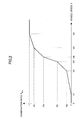
FIG. 2 is an example of a combination ratio map illustrating a correspondence relation between the combination ratio Rratio and the vehicle speed V. The vertical axis corresponds to the combination ratio Rratio and the horizontal axis corresponds to the vehicle speed V. It shows that, with increase of the vehicle speed V, the combination ratio Rratio increases from 0 as the minimum value to 1 as the maximum value according to an increasing rate with five steps. The combination ratio map may be preliminarily stored in the ROM or the NVRAM in thecontrolling part 101. - The increase of the combination ratio Rratio represents that the contribution ratio of the curve radius Ryaw calculated on the yaw rate against the estimate value Rn increases, while the contribution ratio of the curve radius Rstr calculated on the steering angle against the estimated value Rn decreases.
- In the case where the value of the combination ratio is "0", the estimate value Rn of the conclusive curve radius is equal to Rstr (the curve radius Ryaw has no effect on the estimate value Rn, the curve radius estimate value Rn is estimated only on the curve radius Rstr). Meanwhile, in the case where the value of the combination ratio is "1", the estimate value Rn of the conclusive curve radius is equal to Ryaw (the curve radius Rstr has no effect on the estimate value Rn, the curve radius estimate value Rn is estimated only on the curve radius Ryaw) .
- Since the resolution of the
yaw rate sensor 102 is restricted to a certain level (since, at low speed area, the output value of theyaw rate sensor 102 becomes low and the effect of the resolution on the output value becomes large), the curve radius Rstr calculated on the steering angle becomes more reliable than the curve radius Ryaw calculated on the yaw rate at the low speed area. Meanwhile, with increase of the vehicle speed V, the output value of theyaw rate sensor 102 becomes large, the effect of the resolution on the output value becomes low, and thus the curve radius Ryaw calculated on the yaw rate becomes more reliable than the curve radius Rstr calculated on the steering angle. - Referring to
FIG. 2 , in the case where the vehicle speed V is between V1 (2 kilometers per hour for example) and V2 (7 kilometers per hour for example), the combination ratio Rratio increases from value "0" to value R2 at a constant increasing rate α1 with increase of the vehicle speed V, and in the case where the vehicle speed V is between V2 and V3 (9 kilometers per hour for example), the combination ratio Rratio increases from value R2 to value R3 at a constant increasing rate α2 with increase of the vehicle speed V. - Similarly, in the case where the vehicle speed V is between V3 and V4 (10 kilometers per hour for example), the combination ratio Rratio increases from value R3 to value R4 at a constant increasing rate α3 with increase of the vehicle speed V, in the case where the vehicle speed V is between V4 and V5 (12 kilometers per hour for example), the combination ratio Rratio increases from value R4 to value R5 at a constant increasing rate α4 with increase of the vehicle speed V, and in the case where the vehicle speed V is between V5 and V6 (15 kilometers per hour for example), the combination ratio Rratio increases from value R5 to value "1" at a constant increasing rate α5 with increase of the vehicle speed V.
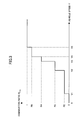
-
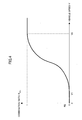
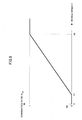
FIGS. 3 to 5 are other examples of the combination ratio map illustrating a correspondence relation between the combination ratio Rratio and the vehicle speed V.FIG.3 shows that the combination ratio Rratio increases in a staircase pattern with five steps with increase of the vehicle speed V from V1 to V5.FIG. 4 show that the combination ratio Rratio increases steplessly along a curve with increase of the vehicle speed V from V1 to V6. Also,FIG. 5 shows that the combination ratio Rratio increases at a constant increasing rate in the case where the vehicle speed V is between V1 and V6. - The value VTH of the vehicle speed V when the combination ratio Rratio reaches the value "1" (corresponding to the vehicle speed V6 in
FIG. 2 , the vehicle speed V5 inFIG. 3 or the like.) depends on the resolution of theyaw rate sensor 102, the higher (the finer) the resolution becomes, the smaller the value VTH becomes. This is because, if the resolution of theyaw rate sensor 102 is high, theyaw rate sensor 102 can detect more accurately the value of the yaw rate which is relatively small level in the case where the vehicle speed V is low and increase the reliability of the curve radius Ryaw calculated on the yaw rate. - The following is an explanation of various parts in the
controlling part 201. - The leading vehicle recognizing part 210 recognizes a leading vehicle driving on the same lane as the self vehicle drives. For example, the leading vehicle recognizing part 210 recognizes as a leading vehicle the closest vehicle within a driving trajectory Z determined by the leading vehicle recognizing part 210 based on the curve radius estimate value Rn from the curve
radius estimating device 100 out of more than one vehicle detected by theradar 202 within the coverage of theradar 202. -
FIG. 6 illustrates a recognition procedure of a leading vehicle.FIG. 6 shows a self vehicle M1 passing through a curve and a leading vehicle M2 driving in front of the self vehicle M1. -
FIG. 6 also shows a coverage W of theradar 202 mounted on the self vehicle M1 and driving trajectories Z1 to Z4 determined based on the curve radius estimate value Rn from the curveradius estimating device 100. - The driving trajectories Z1 to Z4 are the driving trajectories Z of the self vehicle M1 determined based on four different curve radius estimate values Rn. The driving trajectories Z shifts from Z1 to Z4 with decrease of the curve radius estimate value Rn. These four driving trajectories Z1 to Z4 are intended for explanation purposes only, the leading vehicle recognizing part 210 practically chooses a single driving trajectory Z based on a single curve radius estimate value Rn from the curve
radius estimating device 100. A center of a circle derived from the curve radius estimate value Rn is, for example, present on a straight line extending in a vehicle width direction through the centroid of the self vehicle. - Firstly, the leading vehicle recognizing part 210 determines the driving trajectory Z of the self vehicle M1 based on the curve radius estimate value Rn from the curve radius estimating device 100 (supposing that the driving trajectory Z3 is chosen), and then recognizes as the leading vehicle the closest vehicle M2 out of vehicles existing within the coverage W of the
radar 202 and within the driving trajectory Z3 of the self vehicle M1. - If the leading vehicle recognizing part 210 chose the driving trajectory Z1, Z2, or Z4, since the vehicle M2 does not exist within the driving trajectory, the leading vehicle recognizing part 210 does not recognize the vehicle M2 as the leading vehicle.
- The inter-vehicular
distance controlling part 211 controls an inter-vehicular distance between a self vehicle and a leading vehicle. For example, the inter-vehiculardistance controlling part 211 continuously calculates a distance between the self vehicle M1 and the leading vehicle M2 recognized by the leading vehicle recognizing part 210 based on the output of theradar 202, accelerates or decelerates the self vehicle M1 by sending out control signals to thethrottle actuator 203 and thebrake actuator 204 so that the distance is maintained at constant distance. - Next, referring to
FIG. 7 , a process in which the curveradius estimating device 100 estimates the curve radius Rn (hereinafter called "curve radius estimating process) will be explained.FIG. 7 is a flowchart illustrating a flow of the curve radius estimating process. The curveradius estimating device 100 runs the curve radius estimating process repeatedly at a predetermined frequency (every 10 milliseconds for example). - Firstly, the
controlling part 101 obtains a value of a yaw rate from theyaw rate sensor 102 and a value of a steering angle from the steering angle sensor 103 (step S1) . - Then, the
controlling part 101 calculates by the first curveradius calculating part 110 the curve radius Ryaw based on a value of a yaw rate, and calculates by the second curveradius calculating part 111 the curve radius Rstr based on a value of a steering angle (step S2). - Then, the
controlling part 101 obtains a value of the vehicle speed V from the vehicle speed sensor 104 (step S3), and determines the combination ratio Rratio based on the obtained value of the vehicle speed V in reference to the combination ratio map stored in the ROM (step S4). - Then the
controlling part 101 calculates by the curveradius estimating part 112 the curve radius estimate value Rn by applying each of the curve radius Ryaw, the curve radius Rstr, and the combination ratio Rratio to the computational expression Rn = Ryaw ratio + Rstr × (1 - Rratio) (step S5), and outputs the calculated curve radius estimate value Rn to the inter-vehiculardistance controlling device 200. - Next, referring to
FIG. 8 , a process in which the inter-vehiculardistance controlling device 200 controls an inter-vehicular distance between a self vehicle and a leading vehicle (hereinafter called "inter-vehicular distance controlling process) will be explained.FIG. 8 is a flowchart illustrating a flow of the inter-vehicular distance controlling process. The inter-vehiculardistance controlling device 200 repeatedly runs the inter-vehicular distance controlling process in response to the output of the curve radius estimate value Rn from the curveradius estimating device 100. - Firstly, the
controlling part 201 obtains the curve radius estimate value Rn from the curve radius estimating device 100 (step S11). - Then, the
controlling part 201 derives by the leading vehicle recognizing part 210 a driving trajectory which a self vehicle is to follow from the curve radius estimate value Rn (step S12). - Then, the
controlling part 201 recognizes as a leading vehicle the vehicle which is within the coverage of theradar 202 and within the driving trajectory and closest to the self vehicle by the leading vehicle recognizing part 210 (step S13). - If the
controlling part 201 recognizes the leading vehicle (YES at step S13), by the inter-vehiculardistance controlling part 211, thecontrolling part 201 outputs a control signal to thethrottle actuator 203 or thebrake actuator 204 and adjusts the inter-vehicular distance between the self vehicle and the leading vehicle so that the inter-vehicular distance becomes a predetermined distance (step S14). - Meanwhile, if the
controlling part 201 does not recognize the leading vehicle (NO at step S13), by the inter-vehiculardistance controlling part 211, thecontrolling part 201 outputs a control signal to thethrottle actuator 203 and adjusts a vehicle speed of the self vehicle so that the vehicle speed becomes a predetermined speed (step S15). - With the above mentioned configuration, the inter-vehicular distance controlling system SYS1 according to the present embodiment increases the contribution ratio of the curve radius Rstr based on the steering angle which is regarded as reliable at low speed area when the self vehicle is driving at low speed. Hence the inter-vehicular distance controlling system SYS1 can control the inter-vehicular distance between the self vehicle and the leading vehicle while recognizing the leading vehicle more reliably even if the self vehicle is passing through a curve at low speed.
- Also, the inter-vehicular distance controlling system SYS1 can control the inter-vehicular distance between the self vehicle and the leading vehicle continuously without losing sight of the leading vehicle even if the self vehicle approaches a curve at low speed.
- Also, the inter-vehicular distance controlling system SYS1 gradually changes the contribution ratio of each of the curve radius Ryaw and the curve radius Rstr against the curve radius estimate value Rn in response to variation in the vehicle speed V. Hence the inter-vehicular distance controlling system SYS1 can control the inter-vehicular distance between the self vehicle and the leading vehicle continuously without losing sight of the leading vehicle while maintaining reliable estimation of the curve radius even if the self vehicle driving at high speed decelerates and approaches a curve, and passes through the curve at low speed.
- Also, the inter-vehicular distance controlling system SYS1 can control the inter-vehicular distance between the self vehicle and the leading vehicle continuously without losing sight of the leading vehicle while maintaining reliable estimation of the curve radius even if the self vehicle passing through a curve at low speed accelerates and exits the curve.
- Also, the inter-vehicular distance controlling system SYS1 can recognize a leading vehicle reliably even in the case where the self vehicle passes through the curve at low speed. Hence the inter-vehicular distance controlling system SYS1 is suitable for use in the full-range ACC.
-
FIG. 9 is a block diagram illustrating a configuration of an inter-vehicular distance controlling system including a second embodiment of a curve radius estimating device. The inter-vehicular distance controlling system SYS2 is different from the inter-vehicular distance controlling system SYS1 in respect that the curveradius estimating device 100 and the inter-vehiculardistance controlling device 200 inFIG. 1 are integrated. - In this way, the inter-vehicular distance controlling system SYS2 is achieved by incorporating a first curve
radius calculating part 310, a second curveradius calculating part 311, a curveradius estimating part 312, and a leadingvehicle recognizing part 313 according to the present embodiment into the existing inter-vehicular distance controlling device. - The preferable embodiments of the present invention have been explained in detail. However, the present invention shall not be restricted to the above embodiments. Various changes and substitutions may be made to the above embodiments without departing from the scope of the present invention.
- For example, in the above embodiments, the curve
radius estimating part 112 derives the curve radius estimate value Rn so that the total of the contribution ratio (corresponding to Rratio) of the curve radius Ryaw based on the yaw rate and the contribution ratio (corresponding to (1 - Rratio)) of the curve radius Rstr based on the steering angle becomes the value "1" (100%). However, the total of the contribution ratio of the curve radius Ryaw and the contribution ratio of the curve radius Rstr does not always have to be 100%. It may be possible to derive the curve radius estimate value Rn while incorporating a contribution ratio of a curve radius calculated on other output value (for example, a curve radius calculated on shift in relative position of an image of lane marking obtained by an in-vehicle camera) or while calculating weighted average of the curve radius Ryaw and the curve radius Rstr. In the case where the weighted average is calculated, a weight of each of the the curve radius Ryaw and the curve radius Rstr is determined depending on the vehicle speed V. Basically, with decrease of the vehicle speed V, a weight of the curve radius Rstr relatively increases while a weight of the curve radius Ryaw relatively decreases. - Also, in the above embodiments, the curve
radius estimating part 112 derives the curve radius estimate value Rn while determining the combination ratio on the predetermined combination ratio map stored in the ROM or the NVRAM. However, it is possible to switch the combination ratio map depending on a bank angle, a road gradient, or the like, of a road on which the self vehicle is driving. - In this case, the curve
radius estimating part 112 may detect the bank angle, the road gradient, or the like, of the road on which the self vehicle is driving based on road information which a navigation system holds, or may detect the bank angle, the road gradient, or the like, of the road on which the self vehicle is driving based on a output of an inclination sensor and/or an acceleration sensor mounted on the self vehicle. - Also, the curve
radius estimating part 112 chooses a specific combination ratio map corresponding to a specific bank angle from a plurality of combination ratio maps arranged for each bank angle so that the combination ratio Rratio increases with increase of the bank angle even if the vehicle is driving at the same vehicle speed V in the low speed area (15 kilometer per hour or less for example) (so that the contribution ratio of the curve radius Ryaw calculated on the yaw rate against the estimate value Rn becomes large). - This is because, the larger a bank angle at a curve is, the vehicle can pass through the curve with smaller steering angle, and therefore the contribution ratio of the curve radius Rstr calculated on the steering angle against the estimate value Rn should be lowered.
- Meanwhile, the value of the yaw rate is supposed to be corrected based on a value from an inclination sensor or an acceleration sensor which detects acceleration in the vertical direction (a gravitational acceleration for example). This is because, if there exist a bank angle, the value of the yaw rate detected by the
yaw rate sensor 102 is affected by the gravitational acceleration. - Also, in the above embodiments, the curve
radius estimating device 100 outputs the estimated curve radius to the inter-vehiculardistance controlling device 200. However, the curveradius estimating device 100 may output the estimated curve radius to other in-vehicle devices such as a navigation system or a parking assistance device.
Claims (3)
- A curve radius estimating device (100) configured to estimate a curve radius of a lane on which a self vehicle is driving, comprising:a first curve radius calculating part (110, 310) configured to calculate a first curve radius on a steering angle;a second curve radius calculating part (111, 311) configured to calculate a second curve radius on a yaw rate; anda curve radius estimating part (112, 312) configured to estimate a curve radius by combining the first curve radius and the second curve radius at a predetermined combination ratio,characterised in that the curve radius estimating part (112, 312) increases a contribution ratio of the first curve radius against the curve radius with decrease of a vehicle speed.
- A curve radius estimating device (100) according to claim 1, wherein the curve radius estimating part (112, 312) gradually increases a contribution ratio of the first curve radius against the curve radius with decrease of a vehicle speed.
- A curve radius estimating device (100) according to claim 1, wherein the curve radius estimating part (112, 312) changes the predetermined combination ratio depending on a bank angle or a road gradient of a road on which a self vehicle is driving.
Applications Claiming Priority (1)
| Application Number | Priority Date | Filing Date | Title |
|---|---|---|---|
| PCT/JP2009/050986 WO2010084591A1 (en) | 2009-01-22 | 2009-01-22 | Curve radius estimation device |
Publications (3)
| Publication Number | Publication Date |
|---|---|
| EP2380794A1 EP2380794A1 (en) | 2011-10-26 |
| EP2380794A4 EP2380794A4 (en) | 2013-10-30 |
| EP2380794B1 true EP2380794B1 (en) | 2015-05-06 |
Family
ID=42355665
Family Applications (1)
| Application Number | Title | Priority Date | Filing Date |
|---|---|---|---|
| EP20090838782 Not-in-force EP2380794B1 (en) | 2009-01-22 | 2009-01-22 | Curve radius estimation device |
Country Status (4)
| Country | Link |
|---|---|
| US (1) | US8195360B2 (en) |
| EP (1) | EP2380794B1 (en) |
| JP (1) | JP5136657B2 (en) |
| WO (1) | WO2010084591A1 (en) |
Families Citing this family (14)
| Publication number | Priority date | Publication date | Assignee | Title |
|---|---|---|---|---|
| US8989913B2 (en) * | 2008-12-26 | 2015-03-24 | Toyota Jidosha Kabushiki Kaisha | Travel route estimation device and travel route estimation method used in the same device |
| DE102012024970A1 (en) * | 2012-12-20 | 2013-07-04 | Daimler Ag | Method for determining target curve inclination of motor vehicle i.e. motor car, while driving on curvilinear lane section, involves determining road curvature in accordance with acceleration determination using vehicle navigation system |
| US10023103B2 (en) * | 2013-09-13 | 2018-07-17 | J.W. Speaker, Corporation | Systems and methods for illumination control and distribution during a vehicle bank |
| KR102049338B1 (en) * | 2013-11-05 | 2019-11-27 | 현대모비스 주식회사 | Apparatus and method for controlling velocity of vehicle considering slope of road |
| KR102159360B1 (en) * | 2014-09-26 | 2020-09-23 | 현대모비스 주식회사 | Apparatus and Method for Estimating Curvature |
| JP6545108B2 (en) * | 2016-01-14 | 2019-07-17 | アルパイン株式会社 | Parking assistance apparatus and parking assistance method |
| JP6428671B2 (en) * | 2016-02-17 | 2018-11-28 | 株式会社デンソー | Estimator |
| JP2018158689A (en) * | 2017-03-23 | 2018-10-11 | 日野自動車株式会社 | Preceding-vehicle determination apparatus and vehicle control system |
| DE102017106349A1 (en) | 2017-03-24 | 2018-09-27 | Valeo Schalter Und Sensoren Gmbh | A driver assistance system for a vehicle for predicting a traffic lane area, vehicle and method ahead of the vehicle |
| CN107891860A (en) * | 2017-11-14 | 2018-04-10 | 重庆长安汽车股份有限公司 | System and method based on road curvature automatic adjusument speed |
| JP7168353B2 (en) * | 2018-06-13 | 2022-11-09 | 株式会社デンソーテン | Radar device and target data allocation method |
| KR20210067199A (en) * | 2019-11-29 | 2021-06-08 | 현대모비스 주식회사 | Correction system for curvature information using neighboring vehicles and method thereof |
| DE102020107880A1 (en) * | 2020-03-23 | 2021-09-23 | Ford Global Technologies, Llc | Method for controlling a cruise control system in a curve |
| CN117584982B (en) * | 2023-12-28 | 2024-04-23 | 上海保隆汽车科技股份有限公司 | Curve radius estimation method, system, medium, electronic equipment, vehicle machine and vehicle |
Family Cites Families (10)
| Publication number | Priority date | Publication date | Assignee | Title |
|---|---|---|---|---|
| JP3687121B2 (en) * | 1995-02-15 | 2005-08-24 | マツダ株式会社 | Vehicle traveling path estimation device |
| JP3470453B2 (en) | 1995-04-06 | 2003-11-25 | 株式会社デンソー | Inter-vehicle distance control device |
| JP2000002535A (en) * | 1998-06-15 | 2000-01-07 | Daihatsu Motor Co Ltd | Method for detecting curvature of curve road and detector used therefor |
| JP2001328451A (en) * | 2000-05-18 | 2001-11-27 | Denso Corp | Travel route estimating device, preceding vehicle recognizing device and recording medium |
| US7522091B2 (en) | 2002-07-15 | 2009-04-21 | Automotive Systems Laboratory, Inc. | Road curvature estimation system |
| JP3975922B2 (en) | 2003-01-17 | 2007-09-12 | トヨタ自動車株式会社 | Curve radius estimation device |
| WO2005062984A2 (en) * | 2003-12-24 | 2005-07-14 | Automotive Systems Laboratory, Inc. | Road curvature estimation system |
| JP4046742B2 (en) * | 2005-07-14 | 2008-02-13 | 三菱電機株式会社 | Road shape estimation device |
| JP4811147B2 (en) | 2006-06-15 | 2011-11-09 | トヨタ自動車株式会社 | Vehicle control device |
| JP2008176400A (en) * | 2007-01-16 | 2008-07-31 | Mazda Motor Corp | Apparatus for recognizing preceding vehicle |
-
2009
- 2009-01-22 EP EP20090838782 patent/EP2380794B1/en not_active Not-in-force
- 2009-01-22 WO PCT/JP2009/050986 patent/WO2010084591A1/en active Application Filing
- 2009-01-22 JP JP2010547349A patent/JP5136657B2/en not_active Expired - Fee Related
-
2011
- 2011-07-11 US US13/180,136 patent/US8195360B2/en not_active Expired - Fee Related
Also Published As
| Publication number | Publication date |
|---|---|
| JPWO2010084591A1 (en) | 2012-07-12 |
| WO2010084591A1 (en) | 2010-07-29 |
| EP2380794A4 (en) | 2013-10-30 |
| EP2380794A1 (en) | 2011-10-26 |
| JP5136657B2 (en) | 2013-02-06 |
| US20110270466A1 (en) | 2011-11-03 |
| US8195360B2 (en) | 2012-06-05 |
Similar Documents
| Publication | Publication Date | Title |
|---|---|---|
| EP2380794B1 (en) | Curve radius estimation device | |
| EP1602542B1 (en) | Adaptive driver's intention estimation method and system | |
| US6889161B2 (en) | Method for recognizing a change in lane of a vehicle | |
| US6304811B1 (en) | System for controlling speed and distance in a motor vehicle changing traffic lanes | |
| US8489286B2 (en) | Vehicle operation supporting device and vehicle operation supporting method | |
| US9211911B2 (en) | Method for steering assistance during an emergency maneuver | |
| US8330592B2 (en) | Collision warning device for motor vehicles | |
| US9041805B2 (en) | Vibration applying structure detecting device and vehicle control device | |
| EP2060464A2 (en) | Forward collision avoidance assistance system | |
| JP3906821B2 (en) | Lane departure prevention device | |
| US20160209211A1 (en) | Method for determining misalignment of an object sensor | |
| EP2847051B1 (en) | A lane-marking crossing warning system | |
| US20040098197A1 (en) | Automotive lane deviation avoidance system | |
| US20040215393A1 (en) | Automotive lane deviation prevention apparatus | |
| US10967864B2 (en) | Vehicle control device | |
| US20170197630A1 (en) | Control system and method for determining an irregularity of a road surface | |
| US20080228329A1 (en) | Methods and systems for friction detection and slippage control | |
| CN106068215B (en) | Road deviation protection system | |
| JP5114351B2 (en) | Arousal level judgment device | |
| KR102022539B1 (en) | Lane departure warning system | |
| US20220063603A1 (en) | System for and method of recognizing road surface | |
| CN110678778B (en) | Vehicle system for detecting an oncoming vehicle | |
| US6879901B2 (en) | Method for regulating the speed of a vehicle | |
| JP5114342B2 (en) | Arousal level judgment device | |
| JP4615954B2 (en) | Vehicle control object determination device |
Legal Events
| Date | Code | Title | Description |
|---|---|---|---|
| PUAI | Public reference made under article 153(3) epc to a published international application that has entered the european phase |
Free format text: ORIGINAL CODE: 0009012 |
|
| 17P | Request for examination filed |
Effective date: 20110707 |
|
| AK | Designated contracting states |
Kind code of ref document: A1 Designated state(s): AT BE BG CH CY CZ DE DK EE ES FI FR GB GR HR HU IE IS IT LI LT LU LV MC MK MT NL NO PL PT RO SE SI SK TR |
|
| DAX | Request for extension of the european patent (deleted) | ||
| RAP1 | Party data changed (applicant data changed or rights of an application transferred) |
Owner name: TOYOTA JIDOSHA KABUSHIKI KAISHA |
|
| A4 | Supplementary search report drawn up and despatched |
Effective date: 20130926 |
|
| RIC1 | Information provided on ipc code assigned before grant |
Ipc: B60W 30/00 20060101ALI20130920BHEP Ipc: B60W 40/076 20120101ALI20130920BHEP Ipc: B60W 40/06 20120101AFI20130920BHEP Ipc: B60W 40/072 20120101ALI20130920BHEP |
|
| RIC1 | Information provided on ipc code assigned before grant |
Ipc: B60W 30/00 20060101ALI20140905BHEP Ipc: B60W 40/076 20120101ALI20140905BHEP Ipc: B60W 40/06 20120101AFI20140905BHEP Ipc: B60W 40/072 20120101ALI20140905BHEP |
|
| GRAP | Despatch of communication of intention to grant a patent |
Free format text: ORIGINAL CODE: EPIDOSNIGR1 |
|
| INTG | Intention to grant announced |
Effective date: 20141023 |
|
| RIN1 | Information on inventor provided before grant (corrected) |
Inventor name: NAKADORI, MINORU C/O TOYOTA JIDOSHA KABUSHIKI KAIS Inventor name: SAEKI, MINORU C/O TOYOTA JIDOSHA KABUSHIKI KAISHA |
|
| GRAS | Grant fee paid |
Free format text: ORIGINAL CODE: EPIDOSNIGR3 |
|
| GRAA | (expected) grant |
Free format text: ORIGINAL CODE: 0009210 |
|
| AK | Designated contracting states |
Kind code of ref document: B1 Designated state(s): AT BE BG CH CY CZ DE DK EE ES FI FR GB GR HR HU IE IS IT LI LT LU LV MC MK MT NL NO PL PT RO SE SI SK TR |
|
| REG | Reference to a national code |
Ref country code: GB Ref legal event code: FG4D |
|
| REG | Reference to a national code |
Ref country code: CH Ref legal event code: EP |
|
| REG | Reference to a national code |
Ref country code: IE Ref legal event code: FG4D |
|
| REG | Reference to a national code |
Ref country code: AT Ref legal event code: REF Ref document number: 725465 Country of ref document: AT Kind code of ref document: T Effective date: 20150615 |
|
| REG | Reference to a national code |
Ref country code: DE Ref legal event code: R096 Ref document number: 602009031169 Country of ref document: DE Effective date: 20150618 |
|
| REG | Reference to a national code |
Ref country code: AT Ref legal event code: MK05 Ref document number: 725465 Country of ref document: AT Kind code of ref document: T Effective date: 20150506 |
|
| REG | Reference to a national code |
Ref country code: NL Ref legal event code: MP Effective date: 20150506 |
|
| REG | Reference to a national code |
Ref country code: LT Ref legal event code: MG4D |
|
| PG25 | Lapsed in a contracting state [announced via postgrant information from national office to epo] |
Ref country code: ES Free format text: LAPSE BECAUSE OF FAILURE TO SUBMIT A TRANSLATION OF THE DESCRIPTION OR TO PAY THE FEE WITHIN THE PRESCRIBED TIME-LIMIT Effective date: 20150506 Ref country code: PT Free format text: LAPSE BECAUSE OF FAILURE TO SUBMIT A TRANSLATION OF THE DESCRIPTION OR TO PAY THE FEE WITHIN THE PRESCRIBED TIME-LIMIT Effective date: 20150907 Ref country code: HR Free format text: LAPSE BECAUSE OF FAILURE TO SUBMIT A TRANSLATION OF THE DESCRIPTION OR TO PAY THE FEE WITHIN THE PRESCRIBED TIME-LIMIT Effective date: 20150506 Ref country code: FI Free format text: LAPSE BECAUSE OF FAILURE TO SUBMIT A TRANSLATION OF THE DESCRIPTION OR TO PAY THE FEE WITHIN THE PRESCRIBED TIME-LIMIT Effective date: 20150506 Ref country code: LT Free format text: LAPSE BECAUSE OF FAILURE TO SUBMIT A TRANSLATION OF THE DESCRIPTION OR TO PAY THE FEE WITHIN THE PRESCRIBED TIME-LIMIT Effective date: 20150506 Ref country code: NO Free format text: LAPSE BECAUSE OF FAILURE TO SUBMIT A TRANSLATION OF THE DESCRIPTION OR TO PAY THE FEE WITHIN THE PRESCRIBED TIME-LIMIT Effective date: 20150806 |
|
| REG | Reference to a national code |
Ref country code: DE Ref legal event code: R084 Ref document number: 602009031169 Country of ref document: DE |
|
| PG25 | Lapsed in a contracting state [announced via postgrant information from national office to epo] |
Ref country code: IS Free format text: LAPSE BECAUSE OF FAILURE TO SUBMIT A TRANSLATION OF THE DESCRIPTION OR TO PAY THE FEE WITHIN THE PRESCRIBED TIME-LIMIT Effective date: 20150906 Ref country code: AT Free format text: LAPSE BECAUSE OF FAILURE TO SUBMIT A TRANSLATION OF THE DESCRIPTION OR TO PAY THE FEE WITHIN THE PRESCRIBED TIME-LIMIT Effective date: 20150506 Ref country code: LV Free format text: LAPSE BECAUSE OF FAILURE TO SUBMIT A TRANSLATION OF THE DESCRIPTION OR TO PAY THE FEE WITHIN THE PRESCRIBED TIME-LIMIT Effective date: 20150506 Ref country code: BG Free format text: LAPSE BECAUSE OF FAILURE TO SUBMIT A TRANSLATION OF THE DESCRIPTION OR TO PAY THE FEE WITHIN THE PRESCRIBED TIME-LIMIT Effective date: 20150806 Ref country code: GR Free format text: LAPSE BECAUSE OF FAILURE TO SUBMIT A TRANSLATION OF THE DESCRIPTION OR TO PAY THE FEE WITHIN THE PRESCRIBED TIME-LIMIT Effective date: 20150807 |
|
| PG25 | Lapsed in a contracting state [announced via postgrant information from national office to epo] |
Ref country code: DK Free format text: LAPSE BECAUSE OF FAILURE TO SUBMIT A TRANSLATION OF THE DESCRIPTION OR TO PAY THE FEE WITHIN THE PRESCRIBED TIME-LIMIT Effective date: 20150506 Ref country code: EE Free format text: LAPSE BECAUSE OF FAILURE TO SUBMIT A TRANSLATION OF THE DESCRIPTION OR TO PAY THE FEE WITHIN THE PRESCRIBED TIME-LIMIT Effective date: 20150506 |
|
| REG | Reference to a national code |
Ref country code: DE Ref legal event code: R097 Ref document number: 602009031169 Country of ref document: DE |
|
| PG25 | Lapsed in a contracting state [announced via postgrant information from national office to epo] |
Ref country code: RO Free format text: LAPSE BECAUSE OF NON-PAYMENT OF DUE FEES Effective date: 20150506 Ref country code: PL Free format text: LAPSE BECAUSE OF FAILURE TO SUBMIT A TRANSLATION OF THE DESCRIPTION OR TO PAY THE FEE WITHIN THE PRESCRIBED TIME-LIMIT Effective date: 20150506 Ref country code: SK Free format text: LAPSE BECAUSE OF FAILURE TO SUBMIT A TRANSLATION OF THE DESCRIPTION OR TO PAY THE FEE WITHIN THE PRESCRIBED TIME-LIMIT Effective date: 20150506 Ref country code: CZ Free format text: LAPSE BECAUSE OF FAILURE TO SUBMIT A TRANSLATION OF THE DESCRIPTION OR TO PAY THE FEE WITHIN THE PRESCRIBED TIME-LIMIT Effective date: 20150506 |
|
| PLBE | No opposition filed within time limit |
Free format text: ORIGINAL CODE: 0009261 |
|
| STAA | Information on the status of an ep patent application or granted ep patent |
Free format text: STATUS: NO OPPOSITION FILED WITHIN TIME LIMIT |
|
| 26N | No opposition filed |
Effective date: 20160209 |
|
| PG25 | Lapsed in a contracting state [announced via postgrant information from national office to epo] |
Ref country code: IT Free format text: LAPSE BECAUSE OF FAILURE TO SUBMIT A TRANSLATION OF THE DESCRIPTION OR TO PAY THE FEE WITHIN THE PRESCRIBED TIME-LIMIT Effective date: 20150506 |
|
| PG25 | Lapsed in a contracting state [announced via postgrant information from national office to epo] |
Ref country code: BE Free format text: LAPSE BECAUSE OF NON-PAYMENT OF DUE FEES Effective date: 20160131 Ref country code: SI Free format text: LAPSE BECAUSE OF FAILURE TO SUBMIT A TRANSLATION OF THE DESCRIPTION OR TO PAY THE FEE WITHIN THE PRESCRIBED TIME-LIMIT Effective date: 20150506 |
|
| REG | Reference to a national code |
Ref country code: DE Ref legal event code: R119 Ref document number: 602009031169 Country of ref document: DE |
|
| PG25 | Lapsed in a contracting state [announced via postgrant information from national office to epo] |
Ref country code: LU Free format text: LAPSE BECAUSE OF FAILURE TO SUBMIT A TRANSLATION OF THE DESCRIPTION OR TO PAY THE FEE WITHIN THE PRESCRIBED TIME-LIMIT Effective date: 20160122 Ref country code: BE Free format text: LAPSE BECAUSE OF FAILURE TO SUBMIT A TRANSLATION OF THE DESCRIPTION OR TO PAY THE FEE WITHIN THE PRESCRIBED TIME-LIMIT Effective date: 20150506 |
|
| REG | Reference to a national code |
Ref country code: CH Ref legal event code: PL |
|
| GBPC | Gb: european patent ceased through non-payment of renewal fee |
Effective date: 20160122 |
|
| PG25 | Lapsed in a contracting state [announced via postgrant information from national office to epo] |
Ref country code: MC Free format text: LAPSE BECAUSE OF FAILURE TO SUBMIT A TRANSLATION OF THE DESCRIPTION OR TO PAY THE FEE WITHIN THE PRESCRIBED TIME-LIMIT Effective date: 20150506 |
|
| REG | Reference to a national code |
Ref country code: FR Ref legal event code: ST Effective date: 20160930 |
|
| PG25 | Lapsed in a contracting state [announced via postgrant information from national office to epo] |
Ref country code: LI Free format text: LAPSE BECAUSE OF NON-PAYMENT OF DUE FEES Effective date: 20160131 Ref country code: CH Free format text: LAPSE BECAUSE OF NON-PAYMENT OF DUE FEES Effective date: 20160131 Ref country code: GB Free format text: LAPSE BECAUSE OF NON-PAYMENT OF DUE FEES Effective date: 20160122 Ref country code: DE Free format text: LAPSE BECAUSE OF NON-PAYMENT OF DUE FEES Effective date: 20160802 |
|
| REG | Reference to a national code |
Ref country code: IE Ref legal event code: MM4A |
|
| PG25 | Lapsed in a contracting state [announced via postgrant information from national office to epo] |
Ref country code: FR Free format text: LAPSE BECAUSE OF NON-PAYMENT OF DUE FEES Effective date: 20160201 |
|
| PG25 | Lapsed in a contracting state [announced via postgrant information from national office to epo] |
Ref country code: IE Free format text: LAPSE BECAUSE OF NON-PAYMENT OF DUE FEES Effective date: 20160122 |
|
| PG25 | Lapsed in a contracting state [announced via postgrant information from national office to epo] |
Ref country code: NL Free format text: LAPSE BECAUSE OF FAILURE TO SUBMIT A TRANSLATION OF THE DESCRIPTION OR TO PAY THE FEE WITHIN THE PRESCRIBED TIME-LIMIT Effective date: 20150506 Ref country code: SE Free format text: LAPSE BECAUSE OF FAILURE TO SUBMIT A TRANSLATION OF THE DESCRIPTION OR TO PAY THE FEE WITHIN THE PRESCRIBED TIME-LIMIT Effective date: 20150506 |
|
| PG25 | Lapsed in a contracting state [announced via postgrant information from national office to epo] |
Ref country code: MT Free format text: LAPSE BECAUSE OF FAILURE TO SUBMIT A TRANSLATION OF THE DESCRIPTION OR TO PAY THE FEE WITHIN THE PRESCRIBED TIME-LIMIT Effective date: 20150506 |
|
| PG25 | Lapsed in a contracting state [announced via postgrant information from national office to epo] |
Ref country code: CY Free format text: LAPSE BECAUSE OF FAILURE TO SUBMIT A TRANSLATION OF THE DESCRIPTION OR TO PAY THE FEE WITHIN THE PRESCRIBED TIME-LIMIT Effective date: 20150506 Ref country code: HU Free format text: LAPSE BECAUSE OF FAILURE TO SUBMIT A TRANSLATION OF THE DESCRIPTION OR TO PAY THE FEE WITHIN THE PRESCRIBED TIME-LIMIT; INVALID AB INITIO Effective date: 20090122 |
|
| PG25 | Lapsed in a contracting state [announced via postgrant information from national office to epo] |
Ref country code: MT Free format text: LAPSE BECAUSE OF FAILURE TO SUBMIT A TRANSLATION OF THE DESCRIPTION OR TO PAY THE FEE WITHIN THE PRESCRIBED TIME-LIMIT Effective date: 20160131 Ref country code: TR Free format text: LAPSE BECAUSE OF FAILURE TO SUBMIT A TRANSLATION OF THE DESCRIPTION OR TO PAY THE FEE WITHIN THE PRESCRIBED TIME-LIMIT Effective date: 20150506 Ref country code: MK Free format text: LAPSE BECAUSE OF FAILURE TO SUBMIT A TRANSLATION OF THE DESCRIPTION OR TO PAY THE FEE WITHIN THE PRESCRIBED TIME-LIMIT Effective date: 20150506 |