EP2380752A1 - An asymmetrical wheel hub assembly - Google Patents
An asymmetrical wheel hub assembly Download PDFInfo
- Publication number
- EP2380752A1 EP2380752A1 EP11162855A EP11162855A EP2380752A1 EP 2380752 A1 EP2380752 A1 EP 2380752A1 EP 11162855 A EP11162855 A EP 11162855A EP 11162855 A EP11162855 A EP 11162855A EP 2380752 A1 EP2380752 A1 EP 2380752A1
- Authority
- EP
- European Patent Office
- Prior art keywords
- rolling bodies
- row
- wheel hub
- hub assembly
- assembly according
- Prior art date
- Legal status (The legal status is an assumption and is not a legal conclusion. Google has not performed a legal analysis and makes no representation as to the accuracy of the status listed.)
- Granted
Links
Images

Classifications
-
- B—PERFORMING OPERATIONS; TRANSPORTING
- B60—VEHICLES IN GENERAL
- B60B—VEHICLE WHEELS; CASTORS; AXLES FOR WHEELS OR CASTORS; INCREASING WHEEL ADHESION
- B60B27/00—Hubs
- B60B27/0005—Hubs with ball bearings
-
- B—PERFORMING OPERATIONS; TRANSPORTING
- B60—VEHICLES IN GENERAL
- B60B—VEHICLE WHEELS; CASTORS; AXLES FOR WHEELS OR CASTORS; INCREASING WHEEL ADHESION
- B60B27/00—Hubs
- B60B27/0015—Hubs for driven wheels
- B60B27/0021—Hubs for driven wheels characterised by torque transmission means from drive axle
- B60B27/0026—Hubs for driven wheels characterised by torque transmission means from drive axle of the radial type, e.g. splined key
-
- F—MECHANICAL ENGINEERING; LIGHTING; HEATING; WEAPONS; BLASTING
- F16—ENGINEERING ELEMENTS AND UNITS; GENERAL MEASURES FOR PRODUCING AND MAINTAINING EFFECTIVE FUNCTIONING OF MACHINES OR INSTALLATIONS; THERMAL INSULATION IN GENERAL
- F16C—SHAFTS; FLEXIBLE SHAFTS; ELEMENTS OR CRANKSHAFT MECHANISMS; ROTARY BODIES OTHER THAN GEARING ELEMENTS; BEARINGS
- F16C19/00—Bearings with rolling contact, for exclusively rotary movement
- F16C19/02—Bearings with rolling contact, for exclusively rotary movement with bearing balls essentially of the same size in one or more circular rows
- F16C19/14—Bearings with rolling contact, for exclusively rotary movement with bearing balls essentially of the same size in one or more circular rows for both radial and axial load
- F16C19/18—Bearings with rolling contact, for exclusively rotary movement with bearing balls essentially of the same size in one or more circular rows for both radial and axial load with two or more rows of balls
- F16C19/181—Bearings with rolling contact, for exclusively rotary movement with bearing balls essentially of the same size in one or more circular rows for both radial and axial load with two or more rows of balls with angular contact
- F16C19/183—Bearings with rolling contact, for exclusively rotary movement with bearing balls essentially of the same size in one or more circular rows for both radial and axial load with two or more rows of balls with angular contact with two rows at opposite angles
- F16C19/184—Bearings with rolling contact, for exclusively rotary movement with bearing balls essentially of the same size in one or more circular rows for both radial and axial load with two or more rows of balls with angular contact with two rows at opposite angles in O-arrangement
- F16C19/186—Bearings with rolling contact, for exclusively rotary movement with bearing balls essentially of the same size in one or more circular rows for both radial and axial load with two or more rows of balls with angular contact with two rows at opposite angles in O-arrangement with three raceways provided integrally on parts other than race rings, e.g. third generation hubs
-
- B—PERFORMING OPERATIONS; TRANSPORTING
- B60—VEHICLES IN GENERAL
- B60B—VEHICLE WHEELS; CASTORS; AXLES FOR WHEELS OR CASTORS; INCREASING WHEEL ADHESION
- B60B2380/00—Bearings
- B60B2380/10—Type
- B60B2380/12—Ball bearings
-
- B—PERFORMING OPERATIONS; TRANSPORTING
- B60—VEHICLES IN GENERAL
- B60B—VEHICLE WHEELS; CASTORS; AXLES FOR WHEELS OR CASTORS; INCREASING WHEEL ADHESION
- B60B2380/00—Bearings
- B60B2380/70—Arrangements
- B60B2380/73—Double track
-
- B—PERFORMING OPERATIONS; TRANSPORTING
- B60—VEHICLES IN GENERAL
- B60B—VEHICLE WHEELS; CASTORS; AXLES FOR WHEELS OR CASTORS; INCREASING WHEEL ADHESION
- B60B2380/00—Bearings
- B60B2380/70—Arrangements
- B60B2380/76—Twin or multiple bearings having different diameters
-
- B—PERFORMING OPERATIONS; TRANSPORTING
- B60—VEHICLES IN GENERAL
- B60B—VEHICLE WHEELS; CASTORS; AXLES FOR WHEELS OR CASTORS; INCREASING WHEEL ADHESION
- B60B2900/00—Purpose of invention
- B60B2900/10—Reduction of
- B60B2900/121—Resisting forces
- B60B2900/1212—Resisting forces due to friction
-
- F—MECHANICAL ENGINEERING; LIGHTING; HEATING; WEAPONS; BLASTING
- F16—ENGINEERING ELEMENTS AND UNITS; GENERAL MEASURES FOR PRODUCING AND MAINTAINING EFFECTIVE FUNCTIONING OF MACHINES OR INSTALLATIONS; THERMAL INSULATION IN GENERAL
- F16C—SHAFTS; FLEXIBLE SHAFTS; ELEMENTS OR CRANKSHAFT MECHANISMS; ROTARY BODIES OTHER THAN GEARING ELEMENTS; BEARINGS
- F16C2240/00—Specified values or numerical ranges of parameters; Relations between them
- F16C2240/40—Linear dimensions, e.g. length, radius, thickness, gap
- F16C2240/70—Diameters; Radii
- F16C2240/80—Pitch circle diameters [PCD]
-
- F—MECHANICAL ENGINEERING; LIGHTING; HEATING; WEAPONS; BLASTING
- F16—ENGINEERING ELEMENTS AND UNITS; GENERAL MEASURES FOR PRODUCING AND MAINTAINING EFFECTIVE FUNCTIONING OF MACHINES OR INSTALLATIONS; THERMAL INSULATION IN GENERAL
- F16C—SHAFTS; FLEXIBLE SHAFTS; ELEMENTS OR CRANKSHAFT MECHANISMS; ROTARY BODIES OTHER THAN GEARING ELEMENTS; BEARINGS
- F16C2326/00—Articles relating to transporting
- F16C2326/01—Parts of vehicles in general
- F16C2326/02—Wheel hubs or castors
Definitions
- the present invention relates to an asymmetrical wheel hub assembly.
- Asymmetrical wheel hub assemblies of the known type have an axis of rotation and comprise two rows of rolling bodies with pitch diameters of dimensions that differ from one another, an inner flanged ring and an outer ring arranged coaxially with and externally to the inner ring and, for each row of rolling bodies, an inner raceway and an outer raceway obtained, respectively, on the outside of the inner ring and on the inside of the outer ring in positions axially staggered with respect to one another to permit the asymmetrical wheel hub assembly to support combined loads, i.e. loads that act simultaneously in a radial direction and in an axial direction.
- the dimension of the pitch diameter of the row of rolling bodies arranged closest to a flange of the inner flanged ring, i.e. of the row of rolling bodies arranged on the so-called "outboard” side is greater than the dimension of a diameter of the other row of rolling bodies, i.e. of the row of rolling bodies arranged on the so-called “inboard” side.
- the geometry just described confers greater rigidity on the asymmetrical wheel hub assembly, especially if compared with a symmetrical wheel hub assembly in which both pitch diameters are identical and their dimensions are the same as the dimensions of the row of rolling bodies on the "inboard” side.
- Asymmetrical wheel hub assemblies are used in countless applications in the automobile field, but because of the increasingly restrictive anti-pollution regulations that have come into effect in recent years, it has been necessary to study technological solutions aimed, even indirectly, at reducing both the energy consumption of the vehicles and emissions noxious for the environment such as, for example, carbon monoxide emissions.
- the object of the present invention is to provide an asymmetrical wheel hub assembly which, while maintaining high mechanical characteristics and high rigidity, as well as high reliability, permits a significant reduction of consumption and of pollutant emissions.
- an asymmetrical wheel hub assembly with an axis of rotation and two rows of rolling bodies with pitch diameters that differ from one another, an inner raceway and an outer raceway which are arranged in axially staggered positions in accordance with a respective angle of contact and along a respective load line in order to allow the assembly to support combined loads, the raceways of each row of rolling bodies being provided with respective osculations which are defined by the ratio between the radiuses of curvature of the raceways and the outer diameters of the rolling bodies of the associated row of rolling bodies; the asymmetrical wheel hub assembly being characterized in that the angle of contact and the osculations of a first row of rolling bodies of the two rows of rolling bodies are different from the angle of contact and, respectively, from the osculations of a second row of rolling bodies of the two rows of rolling bodies.
- 10 indicates an asymmetrical wheel hub assembly as a whole with an axis A of rotation and comprising an inner ring 11 and an outer ring 12 coaxial with respect to one another and to the axis A of rotation and revolving with respect to one another because of the interposition between them of two rows C1, C2 of rolling bodies 13.
- the rolling bodies 13 are balls, the centres of which are arranged along respective pitch diameters P1, P2.
- the dimensions of the pitch diameter P1 of the row C1 are greater than the dimensions of the pitch diameter P2 of the row C2.
- the assembly 10 comprises, for each row C1 and C2, an inner raceway 111, 112 and an outer raceway 121, 122 arranged in axially staggered positions to permit the assembly 10 to support combined loads, which act simultaneously both in the radial direction and in the axial direction, and are transmitted between balls 13 and inner raceways 111, 112 and between balls 13 and outer raceways 121, 122 along respective load lines L1, L2.
- the load lines L1, L2 join the points of contact between the balls 13 of each row C1, C2 with the associated inner raceways 111, 112 and the associated outer raceways 121, 122, and form respective angles ⁇ and ⁇ of contact with respective lines perpendicular to the axis A in a radial plane.
- the inner raceways 111, 112 are obtained outside the inner ring 11, while the outer raceways 121, 122 are obtained directly on an inner surface 123 of the outer ring 12 which, in the exemplary embodiment illustrated, is provided with an outer flange 124 for anchoring the assembly 10 to a vehicle.
- the inner ring 11 is an inner flanged ring to permit the attachment of a wheel to the assembly 10, and comprises:
- the flange 14 and the ring 16 define, for the assembly 10, the so-called “outboard side” and, respectively, the "inboard side", and the inner raceway 111 of the row C1 is obtained directly on an outer surface 113 of the spindle 15 in the vicinity of the flange 14, while the inner raceway 112 of the row C2 is obtained directly on the applied ring 16.
- the inner raceway 111 of row C1 can be obtained directly on a respective applied ring arranged in an intermediate position between the flange 14 and the ring 16 and axially blocked by the flange 14 and ring 16.
- the raceways 111, 112, 121, 122 have respective osculations O xy defined by the ratio between the radiuses r of curvature of the raceways 111, 112, 121, 122 and the outer diameters ⁇ 1, ⁇ 2 of the balls 13 of each row C1, C2.
- O xy defined by the ratio between the radiuses r of curvature of the raceways 111, 112, 121, 122 and the outer diameters ⁇ 1, ⁇ 2 of the balls 13 of each row C1, C2.
- the osculations O OE , O OI of the row C1 are different from the respective osculations O IE , O II of the row C2.
- the best performance in terms of reduction of friction is obtained when the wheel hub assembly 10 is made according to any one of the following geometrical conditions:
- the different osculation of the outboard side compared with the inboard side can be obtained both by varying the radiuses of curvature of the associated raceways 111, 121 of the outboard side compared with the radiuses of curvature of the raceways of the inboard side, or by varying the outer diameters ⁇ 1, ⁇ 2 of the balls 13.
- the different osculation of the outboard side compared with the inboard side can be obtained by making a wheel hub assembly 10' as alternatively illustrated in figure 3 , in which the outer diameters ⁇ 1 of the balls 13 of the row C1 do not have the same dimensions as the dimensions of the outer diameters ⁇ 2 of the balls 13 of the row C2, as in the example of embodiment described above, but in which the outer diameters ⁇ 1 of the balls 13 of the row C1 have smaller dimensions than those of the outer diameters ⁇ 2 of the balls 13 of the row C2.
- the reduction of the outer diameters ⁇ 1 of the balls 13 entails, with the same dynamic and structural conditions described above, a reduction of the tangential velocity between the balls 13 and raceways and, therefore, a reduction of the friction.
- the wheel hub assembly 10 described above just like the wheel hub assembly 10' with balls 13 of different outer diameters, also has magnitudes of the angles of contact ⁇ , ⁇ with dimensions that differ from one another and, in particular, the angle of contact ⁇ of the row C1 has a greater magnitude than the magnitude of the contact angle ⁇ of the row C2.
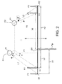
- Figure 2 provides a schematic illustration of the load diagram of the wheel hub assembly 10 of this invention in the case in which it is subjected to a wheel load FR applied in correspondence with the centre PR of application arranged along the axis A of rotation.
- the centre R2 of reaction of the force F2 of reaction is displaced to an axial distance X2 that is smaller than the distance X2' with a consequent increase of the intensity of the force F2 of reaction.
- the reduction of the magnitude of the angle ⁇ of contact gives rise, at kinematic level, to a reduction of the revolution speed of the balls 13 around the axis A with a consequent reduction of the friction between balls 13 and raceways 112, 122.
- the wheel hub assembly 10 is asymmetrical, i.e. k is greater than one, and the angles ⁇ , ⁇ of contact have different magnitudes, the centre R1 of reaction of the force F1 of reaction will be displaced, as compared to the previous case of a symmetrical wheel hub assembly, to an axial distance X1 greater than the distance X1' with a consequent decrease of the intensity of the force F2 of reaction and a better distribution of the forces F1, F2 of reaction without any substantial variation of the speed of revolution of the balls 13 of the row C1 around the axis A.
Landscapes
- Engineering & Computer Science (AREA)
- Mechanical Engineering (AREA)
- General Engineering & Computer Science (AREA)
- Rolling Contact Bearings (AREA)
Abstract
Description
- The present invention relates to an asymmetrical wheel hub assembly.
- Asymmetrical wheel hub assemblies of the known type have an axis of rotation and comprise two rows of rolling bodies with pitch diameters of dimensions that differ from one another, an inner flanged ring and an outer ring arranged coaxially with and externally to the inner ring and, for each row of rolling bodies, an inner raceway and an outer raceway obtained, respectively, on the outside of the inner ring and on the inside of the outer ring in positions axially staggered with respect to one another to permit the asymmetrical wheel hub assembly to support combined loads, i.e. loads that act simultaneously in a radial direction and in an axial direction.
- With asymmetrical wheel hub assemblies of the type described above, the dimension of the pitch diameter of the row of rolling bodies arranged closest to a flange of the inner flanged ring, i.e. of the row of rolling bodies arranged on the so-called "outboard" side, is greater than the dimension of a diameter of the other row of rolling bodies, i.e. of the row of rolling bodies arranged on the so-called "inboard" side. The geometry just described confers greater rigidity on the asymmetrical wheel hub assembly, especially if compared with a symmetrical wheel hub assembly in which both pitch diameters are identical and their dimensions are the same as the dimensions of the row of rolling bodies on the "inboard" side.
- Asymmetrical wheel hub assemblies are used in countless applications in the automobile field, but because of the increasingly restrictive anti-pollution regulations that have come into effect in recent years, it has been necessary to study technological solutions aimed, even indirectly, at reducing both the energy consumption of the vehicles and emissions noxious for the environment such as, for example, carbon monoxide emissions.
- The object of the present invention is to provide an asymmetrical wheel hub assembly which, while maintaining high mechanical characteristics and high rigidity, as well as high reliability, permits a significant reduction of consumption and of pollutant emissions.
- According to the present invention, there is provided an asymmetrical wheel hub assembly with an axis of rotation and two rows of rolling bodies with pitch diameters that differ from one another, an inner raceway and an outer raceway which are arranged in axially staggered positions in accordance with a respective angle of contact and along a respective load line in order to allow the assembly to support combined loads, the raceways of each row of rolling bodies being provided with respective osculations which are defined by the ratio between the radiuses of curvature of the raceways and the outer diameters of the rolling bodies of the associated row of rolling bodies; the asymmetrical wheel hub assembly being characterized in that the angle of contact and the osculations of a first row of rolling bodies of the two rows of rolling bodies are different from the angle of contact and, respectively, from the osculations of a second row of rolling bodies of the two rows of rolling bodies.
- The invention will now be described with reference to the attached drawings which illustrate some non-limitating exemplary embodiments, in which:
-
figure 1 illustrates, in cross section, a first preferred embodiment of an asymmetrical wheel hub assembly made according to this invention; -
figure 2 is a schematic diagram of the distribution of the loads of the wheel hub assembly infigure 1 ; -
figure 3 illustrates, in cross section, a second preferred embodiment of an asymmetrical wheel hub assembly offigure 1 . - With reference to
figure 1 , 10 indicates an asymmetrical wheel hub assembly as a whole with an axis A of rotation and comprising aninner ring 11 and anouter ring 12 coaxial with respect to one another and to the axis A of rotation and revolving with respect to one another because of the interposition between them of two rows C1, C2 ofrolling bodies 13. In the example described here, therolling bodies 13 are balls, the centres of which are arranged along respective pitch diameters P1, P2. In the exemplary embodiment illustrated, the dimensions of the pitch diameter P1 of the row C1 are greater than the dimensions of the pitch diameter P2 of the row C2. - Furthermore, the
assembly 10 comprises, for each row C1 and C2, aninner raceway outer raceway assembly 10 to support combined loads, which act simultaneously both in the radial direction and in the axial direction, and are transmitted betweenballs 13 andinner raceways balls 13 andouter raceways balls 13 of each row C1, C2 with the associatedinner raceways outer raceways - The
inner raceways inner ring 11, while theouter raceways inner surface 123 of theouter ring 12 which, in the exemplary embodiment illustrated, is provided with anouter flange 124 for anchoring theassembly 10 to a vehicle. - The
inner ring 11 is an inner flanged ring to permit the attachment of a wheel to theassembly 10, and comprises: - a
flange 14 transversal to the axis A of rotation, - a
spindle 15 that extends along the axis A of rotation and is made of the same material as theflange 14, and - an applied
inner ring 16, which is fitted on thespindle 15, and is axially blocked by a rollededge 17. - The
flange 14 and thering 16 define, for theassembly 10, the so-called "outboard side" and, respectively, the "inboard side", and theinner raceway 111 of the row C1 is obtained directly on anouter surface 113 of thespindle 15 in the vicinity of theflange 14, while theinner raceway 112 of the row C2 is obtained directly on the appliedring 16. Alternatively, according to a form of embodiment that is not illustrated, theinner raceway 111 of row C1 can be obtained directly on a respective applied ring arranged in an intermediate position between theflange 14 and thering 16 and axially blocked by theflange 14 andring 16. - The
raceways raceways balls 13 of each row C1, C2. In other words, the following osculations are obtained: - OOE: ratio between the radius of curvature of the
outer raceway 111, outboard side, with the outer diameter Φ1; - OIE: ratio between the radius of curvature of the
outer raceway 112, inboard side, and the outer diameter Φ2; - OOI: ratio between the radius of curvature of the
inner raceway 121, outboard side, and the outer diameter Φ1; - OII: ratio between the radius of curvature of the
inner raceway 122, inboard side, and the outer diameter Φ2; - In the example of embodiment illustrated, for the purpose of reducing slipping between the
balls 13 and the associatedraceways wheel hub assembly 10, the osculations OOE, OOI of the row C1 are different from the respective osculations OIE, OII of the row C2. The best performance in terms of reduction of friction is obtained when thewheel hub assembly 10 is made according to any one of the following geometrical conditions: - 1) OOE > OIE; or
- 2) OOI > OII; or
- 3) OOE > OIE and OOI > OII.
- In particular, it was found that the optimum conditions in terms of reduction of friction are obtained when the
wheel hub assembly 10 is made according to any one of the following geometrical conditions: - 1) OOE > 1.004 OIE; or
- 2) OOI > 1.004 OII; or
- 3) OOE > 1.004 OIE and OOI > 1.004 OII.
- The different osculation of the outboard side compared with the inboard side can be obtained both by varying the radiuses of curvature of the associated
raceways balls 13. - In other words, the different osculation of the outboard side compared with the inboard side can be obtained by making a wheel hub assembly 10' as alternatively illustrated in
figure 3 , in which the outer diameters Φ1 of theballs 13 of the row C1 do not have the same dimensions as the dimensions of the outer diameters Φ2 of theballs 13 of the row C2, as in the example of embodiment described above, but in which the outer diameters Φ1 of theballs 13 of the row C1 have smaller dimensions than those of the outer diameters Φ2 of theballs 13 of the row C2. - The reduction of the outer diameters Φ1 of the
balls 13 entails, with the same dynamic and structural conditions described above, a reduction of the tangential velocity between theballs 13 and raceways and, therefore, a reduction of the friction. - In addition to the beneficial effects in terms of reduction of the friction between rolling bodies and raceways as described above as an effect of the ratios between the osculations, and again with the same reduction aims, the
wheel hub assembly 10 described above, just like the wheel hub assembly 10' withballs 13 of different outer diameters, also has magnitudes of the angles of contact α, β with dimensions that differ from one another and, in particular, the angle of contact α of the row C1 has a greater magnitude than the magnitude of the contact angle β of the row C2. -
Figure 2 provides a schematic illustration of the load diagram of thewheel hub assembly 10 of this invention in the case in which it is subjected to a wheel load FR applied in correspondence with the centre PR of application arranged along the axis A of rotation. - The rows C1, C2 of the
wheel hub assembly 10, subjected to the wheel load FR, react with respective forces F1, .F2 of reaction, which are applied in correspondence with the respective centres R1, R2 of reaction which are identified along the axis A of intersection of the associated lines L1, L2 of force with the axis A, and are at axial distances X1, X2 respectively from the centre PR of application. - In particular, it was found that the optimum conditions in terms of reduction of friction are obtained when the values of the trigonometric tangents of the two angles α, β of contact are linked by the following relation:

where:
- With reference to
figure 2 , if the wheel hub assembly is symmetrical, i.e. with k equal to 1, and if the angles α, β' of contact have the same magnitude, the forces of reaction, indicated in this case by F1', F2' would be applied in respective centres R1', R2' of reaction at axial distances X1', X2' respectively from the centre PR of application. - Considering the load diagram of the symmetrical wheel hub assembly 10 (k=1), but with different magnitudes of the angles α , β of contact, i.e. with the magnitude of the angle β smaller than the magnitude of the angle α and smaller than the magnitude of the angle β' and comparing it with the load diagram of a symmetrical wheel hub assembly and with the same magnitudes of the angles α, β, of contact, the centre R2 of reaction of the force F2 of reaction is displaced to an axial distance X2 that is smaller than the distance X2' with a consequent increase of the intensity of the force F2 of reaction. However, the reduction of the magnitude of the angle β of contact gives rise, at kinematic level, to a reduction of the revolution speed of the
balls 13 around the axis A with a consequent reduction of the friction betweenballs 13 andraceways - When, on the other hand, the
wheel hub assembly 10 is asymmetrical, i.e. k is greater than one, and the angles α, β of contact have different magnitudes, the centre R1 of reaction of the force F1 of reaction will be displaced, as compared to the previous case of a symmetrical wheel hub assembly, to an axial distance X1 greater than the distance X1' with a consequent decrease of the intensity of the force F2 of reaction and a better distribution of the forces F1, F2 of reaction without any substantial variation of the speed of revolution of theballs 13 of the row C1 around the axis A. Therefore, in an asymmetricalwheel hub assembly 10, as well as benefitting from greater rigidity, there is also the benefit of better distribution of the forces, thereby allowing theballs 13 of each row C1, C2 to work in better load conditions and with less friction between the raceways and theballs 13 to the complete advantage of consumption and pollutant emissions. - It is intended that the invention not be limited to the embodiments described and illustrated here, which are to be considered as examples of the asymmetrical wheel hub assembly which is, instead, open to further modifications as regards shapes and arrangements of the parts, and constructional and assembly details.
Claims (16)
- An asymmetric wheel hub (10)(10') assembly having an axis (A) of rotation and comprises two rows (C1, C2) of rolling bodies (13) with different pitch diameters (P1, P2) and, for each row (C1)(C2) of rolling bodies (13), an inner raceway (111, 112) and an outer raceway (121, 122), which are axially displaced in accordance with a respective angle of contact and along a respective load line (L1, L2) in order to allow the assembly to support combined loads, the raceways of each row (C1)(C2) of rolling bodies (13) being provided with respective osculations which are defined by the ratio between the radius of the raceways and the outer diameters of the rolling bodies (13) of the associated row of rolling bodies (13); the asymmetric wheel hub assembly being characterized in that the angle of contact and the osculation of a first row (C1) of rolling bodies (13) of the two rows (C1, C2) of rolling bodies (13) are different from the angle of contact and, respectively, the osculation of a second row (C2) of rolling bodies (13) of the two rows (C1, C2) of rolling bodies (13).
- An asymmetric wheel hub assembly according to Claim 1, characterized in that the osculation of the outer raceway (121) of the first row (C1) of rolling bodies (13) has a value which is greater than the value of the osculation of the outer raceway (122) of the second row (C2) of rolling bodies (13).
- An asymmetric wheel hub assembly according to Claim 2, characterized in that the osculation of the outer raceway (121) of the first row (C1) of rolling bodies (13) is 1.004 times greater than the osculation of the outer raceway (122) of the second row (C2) of rolling bodies (13).
- An asymmetric wheel hub assembly according to Claim 1, 2 or 3, characterized in that the osculation of the inner raceway (111) of the first row (C1) of rolling bodies (13) has a value which is greater than the value of the osculation of the inner raceway (112) of the second row (C2) of rolling bodies (13).
- An asymmetric wheel hub assembly according to Claim 4, characterized in that the osculation of the inner raceway (111) of the first row (C1) of rolling bodies (13) is 1.004 times greater than the osculation of the inner raceway (112) of the second row (C2) of rolling bodies (13).
- An asymmetric wheel hub assembly according to Claim 3 or 5, characterized in that the outer diameters of the rolling bodies (13) of the first row (C1) of rolling bodies (13) have sizes which are equal to the sizes of the outer diameters of the rolling bodies (13) of the second row (C2) of rolling bodies (13).
- An asymmetric wheel hub assembly according to Claim 3 or 5, characterized in that the outer diameters of the rolling bodies (13) of the first row (C1) of rolling bodies (13) have sizes which are smaller than the sizes of the outer diameters of the rolling bodies (13) of the second row (C2) of rolling bodies (13).
- An asymmetric wheel hub assembly according to any of the preceding Claims, characterized in that the angle of contact of the first row (C1) of rolling bodies (13) has an magnitude which is greater than the magnitude of the second row (C2) of rolling bodies (13).
- An asymmetric wheel hub assembly according to Claim 8, characterized in that first row (C1) of rolling bodies (13) and the second row (C2) of rolling bodies (13) react to a wheel load (FR), which is applied at a pressure centre (PR) located along the axis (A) of rotation, with a first reaction force (F1) and a second reaction force (F2) which are applied by a respective first reaction centre (R1) and by a respective second reaction centre (R2), and that, having defined:X1: an axial distance between the first reaction centre (R1) and the pressure centre (PR);X2: an axial distance between the second reaction 10 centre (R2) and the pressure centre (PR);P1: a pitch diameter of the first row (C1) of rolling bodies (13);P2: a pitch diameter of the second row (C2) of rolling bodies (13);α: a angle of contact of the first row (C1) of rolling bodies (13);β: a angle of contact of the second row (C2) of rolling bodies (13);
the values of the trigonometric tangent of the two angle of contacts α and β are linked by the following relationship:
where:
- An asymmetric wheel hub assembly according to Claim 9, characterized in that the pitch diameter (P1) of the first row (C1) of rolling bodies (13) is greater than the pitch diameter (P2) of the second row (C2) of rolling bodies (13).
- An asymmetric wheel hub assembly according to Claim 10, characterized in that it also comprises an inner ring (11) and an outer ring (12) which are coaxial with respect to one another and to the rotation axis (A) and which revolve with respect to one another because of the interposition of the two rows (C1, C2) of rolling bodies (13); the inner raceway (111, 112) and the outer raceway (121, 122) of each row (C1)(C2) of rolling bodies (13) being obtained externally to the inner ring (11) and, respectively, internally to the outer ring (12).
- An asymmetric wheel hub assembly according to Claim 11, characterized in that the inner ring (11) is a flanged ring (11) and is provided with a flange (14) which is transversal to the axis (A) of rotation for fitting a wheel.
- An asymmetric wheel hub assembly according to Claim 12, characterized in that the inner raceway (111) of the first row (C1) of rolling bodies (13) is directly obtained on the outside of the inner ring (11) and close to the flange (14).
- An asymmetric wheel hub assembly according to Claim 13, characterized in that the inner ring (11) comprises a spindle (15), which extends along the axis (A) of rotation and is made of the same material as the flange (14); the inner raceway (111) of the first row (C1) of rolling bodies (13) being directly obtained on an outer surface of the spindle (15).
- An asymmetric wheel hub assembly according to Claim 14, characterized in that the inner ring (11) also comprises an applied inner ring (16) which is fitted on the spindle (15); the inner raceway (112) of the second row (C2) of rolling bodies (13) being directly obtained on the applied inner ring (16).
- An asymmetric wheel hub assembly according to Claim 15, characterized in that the outer raceways of the first and of the second row (C2) of rolling bodies (13) are directly obtained on an inner surface of the outer ring (12).
Applications Claiming Priority (1)
| Application Number | Priority Date | Filing Date | Title |
|---|---|---|---|
| ITTO2010A000329A IT1399979B1 (en) | 2010-04-20 | 2010-04-20 | ASYMMETRIC WHEEL HUB GROUP |
Publications (2)
| Publication Number | Publication Date |
|---|---|
| EP2380752A1 true EP2380752A1 (en) | 2011-10-26 |
| EP2380752B1 EP2380752B1 (en) | 2013-06-26 |
Family
ID=42728834
Family Applications (1)
| Application Number | Title | Priority Date | Filing Date |
|---|---|---|---|
| EP11162855.8A Active EP2380752B1 (en) | 2010-04-20 | 2011-04-18 | An asymmetrical wheel hub assembly |
Country Status (4)
| Country | Link |
|---|---|
| US (1) | US8770850B2 (en) |
| EP (1) | EP2380752B1 (en) |
| CN (1) | CN102233792B (en) |
| IT (1) | IT1399979B1 (en) |
Cited By (1)
| Publication number | Priority date | Publication date | Assignee | Title |
|---|---|---|---|---|
| ITTO20130893A1 (en) * | 2013-11-04 | 2015-05-05 | Skf Ab | INTEGRATED GROUP BETWEEN PULLEY AND ROLLING BEARING |
Families Citing this family (7)
| Publication number | Priority date | Publication date | Assignee | Title |
|---|---|---|---|---|
| EP2825782B1 (en) * | 2012-03-15 | 2018-08-01 | Aktiebolaget SKF | Wheel bearing arrangement |
| US9903417B2 (en) * | 2015-04-29 | 2018-02-27 | Aktiebolaget Skf | Assembly procedure of a bearing unit—HUB flange |
| JP2018044670A (en) * | 2016-09-13 | 2018-03-22 | 株式会社ジェイテクト | Hub unit |
| CN106926640B (en) * | 2017-03-02 | 2019-09-10 | 杭州云乐车辆技术有限公司 | A kind of wheel hub with flange |
| JP7456851B2 (en) * | 2019-09-26 | 2024-03-27 | Ntn株式会社 | Double row tapered roller bearing |
| IT202100005837A1 (en) * | 2021-03-12 | 2022-09-12 | Skf Ab | HIGH PERFORMANCE LOW FRICTION WHEEL HUB ASSEMBLY |
| IT202100008999A1 (en) * | 2021-04-12 | 2022-10-12 | Skf Ab | WHEEL HUB ASSEMBLY WITH OPTIMIZED ROLLING TRACKS |
Citations (5)
| Publication number | Priority date | Publication date | Assignee | Title |
|---|---|---|---|---|
| WO2005008085A1 (en) * | 2003-07-10 | 2005-01-27 | Fag Kugelfischer Ag & Co. Ohg | Bearing ring and wheel bearing unit |
| US20050111771A1 (en) * | 2003-10-14 | 2005-05-26 | Shevket Cengiz R. | Asymmetric hub assembly |
| EP1722115A2 (en) * | 2005-05-12 | 2006-11-15 | Ntn Corporation | Wheel support bearing assembly |
| US20090052823A1 (en) * | 2006-04-25 | 2009-02-26 | Ntn Corporation | Bearing Apparatus for a Wheel of Vehicle |
| US20090232435A1 (en) * | 2006-11-14 | 2009-09-17 | Ntn Corporation | Wheel Bearing Apparatus For A Vehicle |
Family Cites Families (6)
| Publication number | Priority date | Publication date | Assignee | Title |
|---|---|---|---|---|
| DE10331936B4 (en) * | 2003-07-15 | 2017-01-26 | Schaeffler Technologies AG & Co. KG | Wheel bearing unit in angular ball bearing design |
| DE102006004297B4 (en) * | 2006-01-31 | 2019-03-07 | Schaeffler Kg | Asymmetrical three-row rolling bearing |
| WO2008029508A1 (en) * | 2006-09-01 | 2008-03-13 | Ntn Corporation | Bearing device for wheel |
| IT1399977B1 (en) * | 2010-04-20 | 2013-05-09 | Skf Ab | WHEEL HUB ASSEMBLY WITH TWO WHEELS OF VOLTAGE BODIES |
| IT1399978B1 (en) * | 2010-04-20 | 2013-05-09 | Skf Ab | WHEEL HUB ASSEMBLY WITH TWO WHEELS OF VOLTAGE BODIES |
| ITTO20100328A1 (en) * | 2010-04-20 | 2011-10-21 | Skf Ab | WHEEL HUB ASSEMBLY WITH TWO WHEELS OF VOLTAGE BODIES |
-
2010
- 2010-04-20 IT ITTO2010A000329A patent/IT1399979B1/en active
-
2011
- 2011-04-18 EP EP11162855.8A patent/EP2380752B1/en active Active
- 2011-04-19 CN CN201110097388.8A patent/CN102233792B/en active Active
- 2011-04-20 US US13/090,684 patent/US8770850B2/en active Active
Patent Citations (5)
| Publication number | Priority date | Publication date | Assignee | Title |
|---|---|---|---|---|
| WO2005008085A1 (en) * | 2003-07-10 | 2005-01-27 | Fag Kugelfischer Ag & Co. Ohg | Bearing ring and wheel bearing unit |
| US20050111771A1 (en) * | 2003-10-14 | 2005-05-26 | Shevket Cengiz R. | Asymmetric hub assembly |
| EP1722115A2 (en) * | 2005-05-12 | 2006-11-15 | Ntn Corporation | Wheel support bearing assembly |
| US20090052823A1 (en) * | 2006-04-25 | 2009-02-26 | Ntn Corporation | Bearing Apparatus for a Wheel of Vehicle |
| US20090232435A1 (en) * | 2006-11-14 | 2009-09-17 | Ntn Corporation | Wheel Bearing Apparatus For A Vehicle |
Cited By (2)
| Publication number | Priority date | Publication date | Assignee | Title |
|---|---|---|---|---|
| ITTO20130893A1 (en) * | 2013-11-04 | 2015-05-05 | Skf Ab | INTEGRATED GROUP BETWEEN PULLEY AND ROLLING BEARING |
| EP2868939A1 (en) * | 2013-11-04 | 2015-05-06 | Aktiebolaget SKF | Pulley-bearing assembly |
Also Published As
| Publication number | Publication date |
|---|---|
| US8770850B2 (en) | 2014-07-08 |
| CN102233792A (en) | 2011-11-09 |
| IT1399979B1 (en) | 2013-05-09 |
| EP2380752B1 (en) | 2013-06-26 |
| CN102233792B (en) | 2015-12-16 |
| ITTO20100329A1 (en) | 2011-10-21 |
| US20110254355A1 (en) | 2011-10-20 |
Similar Documents
| Publication | Publication Date | Title |
|---|---|---|
| EP2380749B1 (en) | A wheel hub assembly with a dual row of rolling bodies | |
| EP2380752B1 (en) | An asymmetrical wheel hub assembly | |
| US8007182B2 (en) | Asymmetrical triple-row anti-friction bearing | |
| EP1722115B1 (en) | Wheel support bearing assembly | |
| US7997803B2 (en) | Multi-row anti-friction bearing | |
| US8075195B2 (en) | Multi-row symmetrical rolling bearing | |
| EP2380750B1 (en) | A wheel hub assembly with a dual row of rolling bodies | |
| CN101512170A (en) | Bearing device for wheel | |
| CN102203443A (en) | Bearing device for wheel | |
| US11273670B2 (en) | Hub unit bearing | |
| EP2380751B1 (en) | A wheel hub assembly with two rows of rolling bodies | |
| EP2990216B1 (en) | Bearing device for wheel | |
| CN208294943U (en) | A kind of hub-bearing unit of biserial difference rolling structure | |
| ITTO20100330A1 (en) | ASYMMETRIC WHEEL HUB GROUP | |
| JP2008106860A (en) | Bearing device for wheel | |
| JP2008157394A (en) | Bearing device for wheel | |
| JP2008101650A (en) | Wheel bearing device |
Legal Events
| Date | Code | Title | Description |
|---|---|---|---|
| AK | Designated contracting states |
Kind code of ref document: A1 Designated state(s): AL AT BE BG CH CY CZ DE DK EE ES FI FR GB GR HR HU IE IS IT LI LT LU LV MC MK MT NL NO PL PT RO RS SE SI SK SM TR |
|
| AX | Request for extension of the european patent |
Extension state: BA ME |
|
| PUAI | Public reference made under article 153(3) epc to a published international application that has entered the european phase |
Free format text: ORIGINAL CODE: 0009012 |
|
| 17P | Request for examination filed |
Effective date: 20120330 |
|
| GRAP | Despatch of communication of intention to grant a patent |
Free format text: ORIGINAL CODE: EPIDOSNIGR1 |
|
| GRAS | Grant fee paid |
Free format text: ORIGINAL CODE: EPIDOSNIGR3 |
|
| GRAA | (expected) grant |
Free format text: ORIGINAL CODE: 0009210 |
|
| AK | Designated contracting states |
Kind code of ref document: B1 Designated state(s): AL AT BE BG CH CY CZ DE DK EE ES FI FR GB GR HR HU IE IS IT LI LT LU LV MC MK MT NL NO PL PT RO RS SE SI SK SM TR |
|
| REG | Reference to a national code |
Ref country code: GB Ref legal event code: FG4D |
|
| REG | Reference to a national code |
Ref country code: CH Ref legal event code: EP |
|
| REG | Reference to a national code |
Ref country code: AT Ref legal event code: REF Ref document number: 618529 Country of ref document: AT Kind code of ref document: T Effective date: 20130715 |
|
| REG | Reference to a national code |
Ref country code: IE Ref legal event code: FG4D |
|
| REG | Reference to a national code |
Ref country code: DE Ref legal event code: R096 Ref document number: 602011002113 Country of ref document: DE Effective date: 20130829 |
|
| REG | Reference to a national code |
Ref country code: SE Ref legal event code: TRGR |
|
| PG25 | Lapsed in a contracting state [announced via postgrant information from national office to epo] |
Ref country code: GR Free format text: LAPSE BECAUSE OF FAILURE TO SUBMIT A TRANSLATION OF THE DESCRIPTION OR TO PAY THE FEE WITHIN THE PRESCRIBED TIME-LIMIT Effective date: 20130927 Ref country code: FI Free format text: LAPSE BECAUSE OF FAILURE TO SUBMIT A TRANSLATION OF THE DESCRIPTION OR TO PAY THE FEE WITHIN THE PRESCRIBED TIME-LIMIT Effective date: 20130626 Ref country code: SI Free format text: LAPSE BECAUSE OF FAILURE TO SUBMIT A TRANSLATION OF THE DESCRIPTION OR TO PAY THE FEE WITHIN THE PRESCRIBED TIME-LIMIT Effective date: 20130626 Ref country code: LT Free format text: LAPSE BECAUSE OF FAILURE TO SUBMIT A TRANSLATION OF THE DESCRIPTION OR TO PAY THE FEE WITHIN THE PRESCRIBED TIME-LIMIT Effective date: 20130626 Ref country code: NO Free format text: LAPSE BECAUSE OF FAILURE TO SUBMIT A TRANSLATION OF THE DESCRIPTION OR TO PAY THE FEE WITHIN THE PRESCRIBED TIME-LIMIT Effective date: 20130926 |
|
| REG | Reference to a national code |
Ref country code: AT Ref legal event code: MK05 Ref document number: 618529 Country of ref document: AT Kind code of ref document: T Effective date: 20130626 |
|
| REG | Reference to a national code |
Ref country code: LT Ref legal event code: MG4D |
|
| PG25 | Lapsed in a contracting state [announced via postgrant information from national office to epo] |
Ref country code: RS Free format text: LAPSE BECAUSE OF FAILURE TO SUBMIT A TRANSLATION OF THE DESCRIPTION OR TO PAY THE FEE WITHIN THE PRESCRIBED TIME-LIMIT Effective date: 20130626 Ref country code: HR Free format text: LAPSE BECAUSE OF FAILURE TO SUBMIT A TRANSLATION OF THE DESCRIPTION OR TO PAY THE FEE WITHIN THE PRESCRIBED TIME-LIMIT Effective date: 20130626 Ref country code: BG Free format text: LAPSE BECAUSE OF FAILURE TO SUBMIT A TRANSLATION OF THE DESCRIPTION OR TO PAY THE FEE WITHIN THE PRESCRIBED TIME-LIMIT Effective date: 20130926 |
|
| REG | Reference to a national code |
Ref country code: NL Ref legal event code: VDEP Effective date: 20130626 |
|
| PG25 | Lapsed in a contracting state [announced via postgrant information from national office to epo] |
Ref country code: LV Free format text: LAPSE BECAUSE OF FAILURE TO SUBMIT A TRANSLATION OF THE DESCRIPTION OR TO PAY THE FEE WITHIN THE PRESCRIBED TIME-LIMIT Effective date: 20130626 |
|
| PG25 | Lapsed in a contracting state [announced via postgrant information from national office to epo] |
Ref country code: BE Free format text: LAPSE BECAUSE OF FAILURE TO SUBMIT A TRANSLATION OF THE DESCRIPTION OR TO PAY THE FEE WITHIN THE PRESCRIBED TIME-LIMIT Effective date: 20130626 Ref country code: AT Free format text: LAPSE BECAUSE OF FAILURE TO SUBMIT A TRANSLATION OF THE DESCRIPTION OR TO PAY THE FEE WITHIN THE PRESCRIBED TIME-LIMIT Effective date: 20130626 Ref country code: PT Free format text: LAPSE BECAUSE OF FAILURE TO SUBMIT A TRANSLATION OF THE DESCRIPTION OR TO PAY THE FEE WITHIN THE PRESCRIBED TIME-LIMIT Effective date: 20131028 Ref country code: CZ Free format text: LAPSE BECAUSE OF FAILURE TO SUBMIT A TRANSLATION OF THE DESCRIPTION OR TO PAY THE FEE WITHIN THE PRESCRIBED TIME-LIMIT Effective date: 20130626 Ref country code: SK Free format text: LAPSE BECAUSE OF FAILURE TO SUBMIT A TRANSLATION OF THE DESCRIPTION OR TO PAY THE FEE WITHIN THE PRESCRIBED TIME-LIMIT Effective date: 20130626 Ref country code: EE Free format text: LAPSE BECAUSE OF FAILURE TO SUBMIT A TRANSLATION OF THE DESCRIPTION OR TO PAY THE FEE WITHIN THE PRESCRIBED TIME-LIMIT Effective date: 20130626 Ref country code: CY Free format text: LAPSE BECAUSE OF FAILURE TO SUBMIT A TRANSLATION OF THE DESCRIPTION OR TO PAY THE FEE WITHIN THE PRESCRIBED TIME-LIMIT Effective date: 20130724 Ref country code: IS Free format text: LAPSE BECAUSE OF FAILURE TO SUBMIT A TRANSLATION OF THE DESCRIPTION OR TO PAY THE FEE WITHIN THE PRESCRIBED TIME-LIMIT Effective date: 20131026 |
|
| PG25 | Lapsed in a contracting state [announced via postgrant information from national office to epo] |
Ref country code: PL Free format text: LAPSE BECAUSE OF FAILURE TO SUBMIT A TRANSLATION OF THE DESCRIPTION OR TO PAY THE FEE WITHIN THE PRESCRIBED TIME-LIMIT Effective date: 20130626 Ref country code: RO Free format text: LAPSE BECAUSE OF FAILURE TO SUBMIT A TRANSLATION OF THE DESCRIPTION OR TO PAY THE FEE WITHIN THE PRESCRIBED TIME-LIMIT Effective date: 20130626 Ref country code: ES Free format text: LAPSE BECAUSE OF FAILURE TO SUBMIT A TRANSLATION OF THE DESCRIPTION OR TO PAY THE FEE WITHIN THE PRESCRIBED TIME-LIMIT Effective date: 20131007 Ref country code: NL Free format text: LAPSE BECAUSE OF FAILURE TO SUBMIT A TRANSLATION OF THE DESCRIPTION OR TO PAY THE FEE WITHIN THE PRESCRIBED TIME-LIMIT Effective date: 20130626 |
|
| PG25 | Lapsed in a contracting state [announced via postgrant information from national office to epo] |
Ref country code: CY Free format text: LAPSE BECAUSE OF FAILURE TO SUBMIT A TRANSLATION OF THE DESCRIPTION OR TO PAY THE FEE WITHIN THE PRESCRIBED TIME-LIMIT Effective date: 20130626 |
|
| PG25 | Lapsed in a contracting state [announced via postgrant information from national office to epo] |
Ref country code: DK Free format text: LAPSE BECAUSE OF FAILURE TO SUBMIT A TRANSLATION OF THE DESCRIPTION OR TO PAY THE FEE WITHIN THE PRESCRIBED TIME-LIMIT Effective date: 20130626 |
|
| PLBE | No opposition filed within time limit |
Free format text: ORIGINAL CODE: 0009261 |
|
| STAA | Information on the status of an ep patent application or granted ep patent |
Free format text: STATUS: NO OPPOSITION FILED WITHIN TIME LIMIT |
|
| 26N | No opposition filed |
Effective date: 20140327 |
|
| REG | Reference to a national code |
Ref country code: DE Ref legal event code: R097 Ref document number: 602011002113 Country of ref document: DE Effective date: 20140327 |
|
| PG25 | Lapsed in a contracting state [announced via postgrant information from national office to epo] |
Ref country code: LU Free format text: LAPSE BECAUSE OF FAILURE TO SUBMIT A TRANSLATION OF THE DESCRIPTION OR TO PAY THE FEE WITHIN THE PRESCRIBED TIME-LIMIT Effective date: 20140418 Ref country code: MC Free format text: LAPSE BECAUSE OF FAILURE TO SUBMIT A TRANSLATION OF THE DESCRIPTION OR TO PAY THE FEE WITHIN THE PRESCRIBED TIME-LIMIT Effective date: 20130626 |
|
| REG | Reference to a national code |
Ref country code: CH Ref legal event code: PL |
|
| REG | Reference to a national code |
Ref country code: IE Ref legal event code: MM4A |
|
| PG25 | Lapsed in a contracting state [announced via postgrant information from national office to epo] |
Ref country code: CH Free format text: LAPSE BECAUSE OF NON-PAYMENT OF DUE FEES Effective date: 20140430 Ref country code: LI Free format text: LAPSE BECAUSE OF NON-PAYMENT OF DUE FEES Effective date: 20140430 |
|
| PG25 | Lapsed in a contracting state [announced via postgrant information from national office to epo] |
Ref country code: IE Free format text: LAPSE BECAUSE OF NON-PAYMENT OF DUE FEES Effective date: 20140418 |
|
| PG25 | Lapsed in a contracting state [announced via postgrant information from national office to epo] |
Ref country code: MT Free format text: LAPSE BECAUSE OF FAILURE TO SUBMIT A TRANSLATION OF THE DESCRIPTION OR TO PAY THE FEE WITHIN THE PRESCRIBED TIME-LIMIT Effective date: 20130626 |
|
| REG | Reference to a national code |
Ref country code: FR Ref legal event code: PLFP Year of fee payment: 6 |
|
| PG25 | Lapsed in a contracting state [announced via postgrant information from national office to epo] |
Ref country code: SM Free format text: LAPSE BECAUSE OF FAILURE TO SUBMIT A TRANSLATION OF THE DESCRIPTION OR TO PAY THE FEE WITHIN THE PRESCRIBED TIME-LIMIT Effective date: 20130626 |
|
| PG25 | Lapsed in a contracting state [announced via postgrant information from national office to epo] |
Ref country code: TR Free format text: LAPSE BECAUSE OF FAILURE TO SUBMIT A TRANSLATION OF THE DESCRIPTION OR TO PAY THE FEE WITHIN THE PRESCRIBED TIME-LIMIT Effective date: 20130626 Ref country code: HU Free format text: LAPSE BECAUSE OF FAILURE TO SUBMIT A TRANSLATION OF THE DESCRIPTION OR TO PAY THE FEE WITHIN THE PRESCRIBED TIME-LIMIT; INVALID AB INITIO Effective date: 20110418 |
|
| REG | Reference to a national code |
Ref country code: FR Ref legal event code: PLFP Year of fee payment: 7 |
|
| REG | Reference to a national code |
Ref country code: FR Ref legal event code: PLFP Year of fee payment: 8 |
|
| PG25 | Lapsed in a contracting state [announced via postgrant information from national office to epo] |
Ref country code: MK Free format text: LAPSE BECAUSE OF FAILURE TO SUBMIT A TRANSLATION OF THE DESCRIPTION OR TO PAY THE FEE WITHIN THE PRESCRIBED TIME-LIMIT Effective date: 20130626 |
|
| PG25 | Lapsed in a contracting state [announced via postgrant information from national office to epo] |
Ref country code: AL Free format text: LAPSE BECAUSE OF FAILURE TO SUBMIT A TRANSLATION OF THE DESCRIPTION OR TO PAY THE FEE WITHIN THE PRESCRIBED TIME-LIMIT Effective date: 20130626 |
|
| PGFP | Annual fee paid to national office [announced via postgrant information from national office to epo] |
Ref country code: SE Payment date: 20190429 Year of fee payment: 9 Ref country code: FR Payment date: 20190429 Year of fee payment: 9 |
|
| PGFP | Annual fee paid to national office [announced via postgrant information from national office to epo] |
Ref country code: GB Payment date: 20190429 Year of fee payment: 9 |
|
| PG25 | Lapsed in a contracting state [announced via postgrant information from national office to epo] |
Ref country code: FR Free format text: LAPSE BECAUSE OF NON-PAYMENT OF DUE FEES Effective date: 20200430 Ref country code: SE Free format text: LAPSE BECAUSE OF NON-PAYMENT OF DUE FEES Effective date: 20200419 |
|
| GBPC | Gb: european patent ceased through non-payment of renewal fee |
Effective date: 20200418 |
|
| PG25 | Lapsed in a contracting state [announced via postgrant information from national office to epo] |
Ref country code: GB Free format text: LAPSE BECAUSE OF NON-PAYMENT OF DUE FEES Effective date: 20200418 |
|
| P01 | Opt-out of the competence of the unified patent court (upc) registered |
Effective date: 20230513 |
|
| PGFP | Annual fee paid to national office [announced via postgrant information from national office to epo] |
Ref country code: DE Payment date: 20250428 Year of fee payment: 15 |
|
| PGFP | Annual fee paid to national office [announced via postgrant information from national office to epo] |
Ref country code: IT Payment date: 20250422 Year of fee payment: 15 |
|
| REG | Reference to a national code |
Ref country code: DE Ref legal event code: R082 Ref document number: 602011002113 Country of ref document: DE Representative=s name: SCHONECKE, MITJA, DIPL.-PHYS. DR. RER. NAT., DE Ref country code: DE Ref legal event code: R082 Ref document number: 602011002113 Country of ref document: DE Representative=s name: SCHONECKE, MITJA, DR., DE |
|
| REG | Reference to a national code |
Ref country code: DE Ref legal event code: R082 Ref document number: 602011002113 Country of ref document: DE Representative=s name: SCHONECKE, MITJA, DR., DE |