EP2380364B1 - Generating an output signal by send effect processing - Google Patents
Generating an output signal by send effect processing Download PDFInfo
- Publication number
- EP2380364B1 EP2380364B1 EP09796455A EP09796455A EP2380364B1 EP 2380364 B1 EP2380364 B1 EP 2380364B1 EP 09796455 A EP09796455 A EP 09796455A EP 09796455 A EP09796455 A EP 09796455A EP 2380364 B1 EP2380364 B1 EP 2380364B1
- Authority
- EP
- European Patent Office
- Prior art keywords
- input signal
- signal
- component signals
- weighted
- parameters
- Prior art date
- Legal status (The legal status is an assumption and is not a legal conclusion. Google has not performed a legal analysis and makes no representation as to the accuracy of the status listed.)
- Active
Links
- 230000000694 effects Effects 0.000 title claims description 75
- 238000012545 processing Methods 0.000 title claims description 44
- 238000000034 method Methods 0.000 claims description 19
- 238000004590 computer program Methods 0.000 claims description 3
- 239000011159 matrix material Substances 0.000 description 14
- 230000006978 adaptation Effects 0.000 description 6
- 230000001419 dependent effect Effects 0.000 description 4
- 230000006870 function Effects 0.000 description 4
- 230000008569 process Effects 0.000 description 4
- 230000000295 complement effect Effects 0.000 description 3
- 238000009877 rendering Methods 0.000 description 3
- 241001342895 Chorus Species 0.000 description 2
- 230000003044 adaptive effect Effects 0.000 description 2
- HAORKNGNJCEJBX-UHFFFAOYSA-N cyprodinil Chemical compound N=1C(C)=CC(C2CC2)=NC=1NC1=CC=CC=C1 HAORKNGNJCEJBX-UHFFFAOYSA-N 0.000 description 2
- 230000008447 perception Effects 0.000 description 2
- 230000002123 temporal effect Effects 0.000 description 2
- 230000001755 vocal effect Effects 0.000 description 2
- 238000005303 weighing Methods 0.000 description 2
- 101100072002 Arabidopsis thaliana ICME gene Proteins 0.000 description 1
- 238000007792 addition Methods 0.000 description 1
- 230000002411 adverse Effects 0.000 description 1
- 230000002238 attenuated effect Effects 0.000 description 1
- 230000009286 beneficial effect Effects 0.000 description 1
- 230000015572 biosynthetic process Effects 0.000 description 1
- 230000003111 delayed effect Effects 0.000 description 1
- 210000005069 ears Anatomy 0.000 description 1
- 238000000605 extraction Methods 0.000 description 1
- 238000012805 post-processing Methods 0.000 description 1
- 238000000638 solvent extraction Methods 0.000 description 1
- 230000007480 spreading Effects 0.000 description 1
- 238000003786 synthesis reaction Methods 0.000 description 1
Images


Classifications
-
- H—ELECTRICITY
- H04—ELECTRIC COMMUNICATION TECHNIQUE
- H04S—STEREOPHONIC SYSTEMS
- H04S3/00—Systems employing more than two channels, e.g. quadraphonic
- H04S3/002—Non-adaptive circuits, e.g. manually adjustable or static, for enhancing the sound image or the spatial distribution
-
- H—ELECTRICITY
- H04—ELECTRIC COMMUNICATION TECHNIQUE
- H04S—STEREOPHONIC SYSTEMS
- H04S2400/00—Details of stereophonic systems covered by H04S but not provided for in its groups
- H04S2400/01—Multi-channel, i.e. more than two input channels, sound reproduction with two speakers wherein the multi-channel information is substantially preserved
-
- H—ELECTRICITY
- H04—ELECTRIC COMMUNICATION TECHNIQUE
- H04S—STEREOPHONIC SYSTEMS
- H04S2420/00—Techniques used stereophonic systems covered by H04S but not provided for in its groups
- H04S2420/01—Enhancing the perception of the sound image or of the spatial distribution using head related transfer functions [HRTF's] or equivalents thereof, e.g. interaural time difference [ITD] or interaural level difference [ILD]
-
- H—ELECTRICITY
- H04—ELECTRIC COMMUNICATION TECHNIQUE
- H04S—STEREOPHONIC SYSTEMS
- H04S2420/00—Techniques used stereophonic systems covered by H04S but not provided for in its groups
- H04S2420/03—Application of parametric coding in stereophonic audio systems
Definitions
- the invention relates to a method of and device for generating an output signal from an input signal by applying a send effect processing to the input signal, wherein the input signal comprises a weighted sum of component signals, wherein dependencies between the weighted component signals are represented by parameters.
- the invention also relates to a binaural decoder for generating an improved binaural output signal, and a computer program product.
- MPEG Surround is one of major advances in audio coding recently standardized by MPEG, see ISO/IEC 23003-1 MPEG Surround.
- MPEG Surround is a multi-channel audio coding tool that allows existing mono- and stereo-based coders to be extended to multi-channel.
- the MPEG Surround encoder typically creates a mono or stereo downmix from the multi-channel input signal, and derives spatial parameters from the multi-channel input signal.
- the downmix and spatial parameters are encoded in separate streams. However, the spatial parameters stream can be embedded in the downmix stream.
- the MPEG Surround decoder decodes the spatial parameters that are used to upmix the decoded downmix in order to obtain the multi-channel output signal.
- MPEG Surround allows decoding the encoded stereo downmix onto other rendering devices, such as these comprising a reproduction on headphones.
- This particular mode of operation is referred to as the MPEG Surround binaural decoding process in which the spatial parameters are combined with the Head Related Transfer Function (HRTF) data (J. Breebaart, Analysis and Synthesis of Binaural Parameters for Efficient 3D Audio Rendering in MPEG Surround, ICME 07) to produce the so-called binaural output.
- HRTF Head Related Transfer Function
- HRTF Head Related Transfer Function
- the MPEG Surround binaural decoder When the MPEG Surround binaural decoder is operated in a Low Power (LP) mode it can be implemented in mobile devices. In this mode in an offline process the raw HRTF data has been converted to a parametric domain allowing processing using low computational complexity.
- LP mode a disadvantage of the LP mode is that the parametric HRTF data represents typically only an anechoic portion of the raw HRTF data, i.e. it only covers a part of complete time domain responses which is primarily associated to directional cues. In practice, this means that the binaural decoder output signal will contain directional information, but will not sound very natural since there is hardly any externalization, which is primarily associated with the echoic part of the HRTF data.
- the MPEG Surround standard allows a use of a reverberation, as prescribed in ISO/IEC 23003-1 MPEG Surround Annex D.
- the MPEG Surround binaural decoder is extended with parallel reverberation.
- the input stereo downmix is fed to the reverberation process.
- the output of this process is directly added to the MPEG Surround binaural output.
- a parallel reverberation signal that is typically omni-directional, i.e. independent of direction, the echoic part is created and thus a more realistic surround experience is created.
- the invention is defined by the independent claims.
- the dependent claims define advantageous embodiments.
- This object is achieved according to the present invention in a method of generating the output signal as stated above and characterized in that the output signal is generated in dependence of the parameters to compensate for an unequal weighting of component signals comprised in the input signal.
- the send effects are applied to the input signal as a whole and not to the individual component signals. Therefore, it is especially advantageous, to compensate for the unequal weighting of the component signals in the input signal while applying a send effect. Due to this compensation the strength of the send effect corresponding to the separate component signals is (nearly) proportional to the strength of each of the component signals, and thus resulting in more realistic surround experience.
- the invention is explained for a reverberation effect as an example of the send effect.
- Reverberation is typically used to simulate acoustic reflections and can therefore be used in conjunction with (anechoic) HRTF data to place virtual sound sources out of the listener's head, i.e. in order to create a perception of a distance.
- the input signal is a downmix of component signals (e.g. the 6 channels of a multichannel representation) that are weighted before downmixing.
- the component signals corresponding to surround channels comprised in a multichannel signal are attenuated before downmixing.
- the component signal corresponding to the center channel is effectively amplified in a stereo downmix (sqrt(0.5) per channel amounts to sqrt(2) when summing left and right downmix channel).
- This unequal weighting of the component signals comprised in the input signal results in the reverberation effect that is stronger for the component corresponding to the center channel and weaker for the components corresponding to the surround channels since a parallel reverberation employs the reverberation directly on the unequally weighted downmix.
- This adaptation makes use of the parameters which comprise dependencies between the weighted component signals.
- the individually weighted components or combinations of the weighted components contributing to the input signal are not available anymore, as the component signals have been summed up (downmixed) after the weighting.
- the parameters allow for estimation of their contributions based on the dependencies between the weighted component signals represented by the parameters.
- the adaptation of the generation of the output signal can be made, which are discussed in the following embodiments.
- the input signal is decomposed into a plurality of intermediate signals, wherein each of the intermediate signals is scaled with a respective gain to compensate for the unequal weighting of component signals comprised in the input signal.
- Generating intermediate signals is beneficial when information from multiple component signals can be combined into the intermediate signals.
- left and right channel signals of the input signal both contain information from the center channel, when the MPEG Surround standard is used in a stereo compatible fashion.
- the intermediate signal corresponding to a center channel can be constructed using both left and right signals of the input signal.
- the multichannel signal comprises five channel signals, i.e.
- the center channel signal, a left front channel signal, a left surround channel signal, a right front channel signal, and a right surround channel signal can be combined in the intermediate signal, as well as the right front channel signal and the right surround channel signal can also be combined in the intermediate signal.
- the respective gain corresponding to the respective intermediate signal is calculated as a weighted sum of predetermined further gains, wherein the predetermined further gains are derived from weights used to create the input signal, wherein the predetermined further gains are weighted with respective weights that are derived from relative contributions of the weighted component signals to the respective intermediate signal.
- MPEG Surround prescribes, for example, that OTT (one-to-two) processing block is used to create two signals from a single signal using the inter-channel intensity difference (IID) parameters, or TTT (two-to-three) processing block is used to create three signals from two signals, using channel prediction parameters and/or IID parameters.
- the gains can be applied on the signals created using the OTT and/or TTT processing blocks and the resulting signals can be downmixed again (a single channel is required for the send effect after all).
- the upmix step i.e. creating multiple intermediate signals from the input signal, can be omitted because the energy distribution related to intermediate signals is known.
- the current embodiment offers an efficient way to apply the gains to the intermediate signals, without actual restoring of the individual component signals contributing to these intermediate signals.
- the relative contribution of the weighted component signals to the respective intermediate signal is derived from an intensity difference between the weighted component signals contributing to the intermediate signal, wherein the intensity difference is derived from the parameters.
- the energy distribution among the weighted component signals is comprised in the inter-channel intensity differences, which in turn are comprised in the parameters accompanying the input signal.
- the input signal is scaled with a gain calculated as a weighted sum of further gains, wherein the further gains are derived from the parameters corresponding to the weighted component signals, wherein the further gains are weighted with weights that are derived from relative contributions of the weighted component signals or combinations of the weighted component signals to the input signal.
- the relative contribution of the weighted component signals or the combinations of the weighted component signals are derived from intensity differences between weighted component signals contributing to the input signal, wherein the intensity differences are derived from the parameters.
- the OTT processing blocks are energy preserving, thus the energy distribution of the weighted component signals in the input signal is calculated based on the intensity differences comprised in the parameters. This distribution is relative to the energy of the input signal, thus an OTT processing block distributes the energy of its input signal over two output channels. Applying gains to the individual component signals can therefore be effectuated by applying a single gain to the input signal.
- generating the output signal comprises adapting send effect processing applied to the input signal, based on the parameters.
- generating the output signal comprises adapting the output signal itself, wherein the output signal is scaled with a gain that is adjusted in dependence of parameters.
- the output signal of send effect processing that is effected by e.g. a large time interval of the input signal (as it is often the case for reverberation filters)
- the parameters corresponding to certain time intervals may be mixed in a signal dependent manner due to the temporal smearing. In such a case it is advantageous to adapt the gain over time in dependence of the parameters, as well as the effect and signal properties.
- the input signal and the parameters are the downmix signal and the spatial parameters, respectively, in accordance with the MPEG Surround standard.
- the component signals are formed by the channels of a multichannel source (e.g. 5.1 audio from a DVD, multichannel recording with a multi-channel microphone), the spatial parameters describe relations between the channels or combinations (intermediate downmixes) of channels in a time- and frequency dependent manner.
- a send effect device for generating an output signal from an input signal by applying a send effect processing to the input signal.
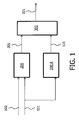
- Fig. 1 shows an example of an architecture of a binaural renderer 200 with a send effect processing device 100-A in parallel.
- the input signal 101 comprising a weighted sum of component signals, together with parameters 102 comprising dependencies between the weighted component signals are fed to the binaural renderer 200.
- the binaural renderer 200 performs a processing of the input signal 101 and the parameters 102 to provide a binaural output 201 which is suitable for reproduction by headphones.
- One of the examples of the binaural renderer is MPEG Surround binaural decoding (ISO/IEC 23003-1, MPEG Surround).
- the input signal 101 1 is fed in parallel to the binaural renderer 200 to the send effect device 100-A, which applies send effect processing to the input signal 101 resulting in the output signal 121.
- the output signal 121 is added by the adding circuit 300 to the output of the binaural renderer.
- the output 301 of the adding circuit is provided to the headphones (not shown).
- send effects such as e.g. reverberation, chorus, vocal doubler, fuzz, space expander, etc.
- Reverberation is one of the most popular send effects, which can be used to place virtual sound sources out of the listener's head, i.e. in order to create a perception of a distance.
- the creation of reverberated signal from the input signal is described in e.g. William G.
- the invention proposes a method of generating an output signal 121 by applying a send effect processing to the input signal 101, which compensates for an unequal weighing of component signals in the input signal 101 in dependence of the parameters 102.
- the component signals contributing to the input signal 101 1 are often unequally weighted.
- the send effect device 100 generates the output signal 121 in such a manner that the unequal weighting is compensated for in dependence of the parameters 102.
- Parameters 102 comprise dependencies between the weighted component signals.
- parameters 102 comprise information about relative contributions of individual weighted component signals to the input signal 101.
- the parameters 102 allow estimating of the weighted component signals relative to the input signal. Since the weights used to weigh the component signals are known, since they are prescribed by the MPEG Surround bit-stream and decoder, the component signals themselves can be estimated. This leads to efficient processing in order to compensate the unequal weighting of the component signals in the input signal 101.
- Fig. 2 shows an embodiment of a send effect device according to the invention.
- the effect processing device 100 differs from the effect processing devices 100-A of the Fig. 1 in that it has the parameters 102 as additional input. Further, the effect processing device 100 of Fig. 2 implements the step of generating the output signal 121 that is adaptive to compensate for an unequal weighting of component signals comprised in the input signal in dependence of the parameters 102.
- generating the output signal 121 comprises adapting the input signal 101.
- the step of adapting the input signal precedes the step of applying a send effect processing.
- Fig. 3 shows an embodiment of a send effect device comprising adapting the input signal 101.
- the send effect device comprises two circuits, namely, an adapting circuit 120 that performs the step of adapting the input signal, and the send effect processing circuit 110 that performs the step of applying a send effect processing.
- the input signal 101 and the parameters 102 are fed into the circuit 120, whose output 103 is fed into the circuit 110.
- the output of the circuit 110 serves as an output signal 121.
- the input signal 101 can be either a mono signal or stereo signal.
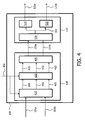
- Fig. 4 shows an example of an architecture of the send effect device 100, wherein the input signal 101 is decomposed into a plurality of intermediate signals 401, 402, and 403, each of the intermediate signals being scaled with a respective gain.
- the input signal 101 is a stereo signal and it comprises a left channel 101 a of the input signal 101 and a right channel 101b of the input signal 101.
- the input signal is fed into a circuit 410, which performs upmixing of the input signal into three intermediate signals, which correspond to a left channel, a right channel, and a center channel. These three signals are referred to as a left intermediate signal, a right intermediate signal, and a center intermediate signal, respectively.
- the circuit 410 can be the Two-To-Three (TTT) module known from the MPEG Surround.
- TTT Two-To-Three
- l dmx being the left channel of the input signal
- r dmx being the right channel of the input signal
- T umx being the matrix representing the decoder TTT module multiplied by the artistic downmix inversion and/or matrix compatibility inversion and/or 3D inversion matrix (respective subclauses 6.5.2.3, 6.5.2.4 and 6.11.5 of MPEG Surround specification):
- T umx c 11 c 12 c 21 c 22 c 31 c 32
- the output of the circuit 410 is a result of the matrix multiplication: T umx ⁇ l dmx r dmx .
- the parameters 102 are also fed into the circuit 410.
- the resulting intermediate signals are fed into a gain compensation circuit 420, in which each of the intermediate signals is scaled with a respective gain to compensate the unequal weighting of the component signals comprised in the input signal.
- the gains G l and G r are employed to compensate for any power loss due to surround gain g s .
- the gain G c is employed to compensate for the power increase due to the center gain g c .
- the respective gain G l , G r , or G c corresponding to the respective intermediate signal is calculated as a weighted sum of predetermined further gains, wherein the predetermined further gains are derived from weights used to create the input signal 101. These predetermined further gains are weighted with respective weights that are derived from relative contributions of the weighted component signals to the respective intermediate signal.
- g s is the actual weight that has been used to scale the surround channel signal contributing to the input signal
- f ( IID l ) is a relative contribution of the weighted component signal corresponding to the left front channel to the left intermediate signal
- (1- f ( IID ⁇ )) is a relative contribution of the weighted component signal corresponding to the left surround channel to the left intermediate signal.
- the index I stands for "left” and the index r stands for "right” to differentiate between the left channel and the right channel
- the relative contribution of the weighted component signals to the respective intermediate signal is derived from an intensity difference IID l , or IID r (where the indices l and r stand for "left channel” and “right channel” respectively), between the weighted component signals contributing to the intermediate signal, wherein the intensity difference is derived from the parameters 102.
- IID l is the logarithmic inter-channel intensity difference (IID) between the weighted left front channel and the weighted left surround channel
- IID r logarithmic inter-channel intensity difference (IID) between the weighted right front channel and the weighted right surround channel.
- IID l is the logarithmic inter-channel intensity difference (IID) between the weighted left front channel and the weighted left surround channel
- IID r logarithmic inter-channel intensity difference (IID) between the weighted right front channel and the weighted right surround channel.
- the scaled intermediate signals 421, 422, and 423 are fed into the circuit 430, which is the Three-To-Two (inverse-TTT) encoder module known from the MPEG Surround.
- the circuit 430 downmixes the three scaled intermediate signals into the signal 103 which subsequently is fed into the send effect processing circuit 110.
- T dmx being the matrix representing the inverse-TTT module
- the signals 103a and 103b can be expressed as the result of the following matrix multiplication: T dmx ⁇ G ⁇ T umx ⁇ l dmx r dmx .
- circuits 410, 420, and 430 are depicted as separate circuits in Fig. 4 , the actual hardware or software implementation does not require this strict circuit partitioning. The processing performed in these circuits can be combined for efficiency reasons. Furthermore, the matrix multiplication can be performed on a processor, without making the intermediate signals explicitly visible.
- the circuit 110 depicts the send effect processing circuit, which comprises circuits 530, 520, and 510.
- the downmixing of the stereo signal 103 which resulted from adapting the input signal 101, is done resulting in a mono downmix 501.
- This downmix 501 is fed in parallel to the circuits 520 and 510 which create the reverberation output signal 121 from the downmix signal 501.
- the processing used in the circuits 510 and 520 can be as described in William G. Gardner, "Reverberation Algorithms" in "Applications of Digital Signal Processing to Audio and Acoustics". Mark Kahrs and Karlheinz Brandenburg (Editors), Kluwer, March 1998 , or Shreyas A.
- the number of the intermediate signals is three, the number of intermediate signals is not restricted to three only and it could take any other value. However, the number of intermediate signals should preferably not exceed the number of the component signals. For MPEG Surround when the input signal is mono the preferable number of intermediate signals takes the following values: two, three, or five, which relates to specific configurations favoured by MPEG Surround.
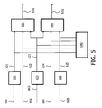
- Fig. 5 shows an example of an architecture of a stereo compatible MPEG Surround encoder, and it illustrates how the input signal 101 is created.
- the signals 601 till 605 are respectively, the surround left channel, the front left channel, the central channel, the front right channel, and the surround right channel. These signals correspond to the component signals from which the input signal 101 is created.
- the circuits 610, 620, and 630 implement scaling with gains.
- the circuit 610 scales the signal 601 with the gain g s .
- the circuit 620 scales the signal 603 with the gain g c .
- the circuit 630 scales the signal 605 with the gain g s .
- the remaining signals 602 and 604 are also scaled, however since the gain used for scaling them typically takes on value 1, the circuits implementing this scaling is omitted in the figure (for this reason the signal 602 is also referred to as 622, as well as the signal 604 is also referred to as 624).
- the parameters 102 are derived from the weighted signals 601 till 605 in the parameter extraction circuit 640.
- the left signal 631 and the right signal 632 are obtained from additions performed in the summation circuits 650 and 660.
- the signals 621 and 622 related to the left channel are added up with the signal 623 related to the center channel in the circuit 650.
- the signals 625 and 624 related to the right channel are added up with the signal 623 related to the center channel in the circuit 660.
- the signals 631 and 632 are subsequently encoded.
- the stereo input signal 101 represents signals 631 and 632 after decoding.
- the input signal 101 can also be a mono signal.
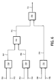
- Fig. 6 shows an example of an architecture of MPEG Surround downmixing in 515 configuration, which creates a mono input signal.
- Circuits 710, 720, 730, 740, and 750 are the inverse-One-To-Two modules which downmix two signals into one signal.
- Index j takes on values 1 or 2 and indicates the output channel of the corresponding OTT box i in the MPEG Surround decoder configuration (inverse of Fig. 6 ).
- the expression for c i,j uses a specific type of function f ( IID ), however other types are also possible.
- IID function f
- the above configuration is one of the possible configurations prescribed by the MPEG Surround. Other configurations are also possible, however the expression for the gain g should be adapted to the configuration used.
- Table 1 shows the gain values for g 1 till g 6 , which are derived from weights used to create the input signal 101.
- the input signal 101 is scaled with a gain 120 calculated as a weighted sum of further gains, wherein the further gains are derived from the parameters 102 corresponding to the weighted component signals, wherein the further gains are weighted with weights that are derived from relative contributions of the weighted component signals or combinations of the weighted component signals to the input signal.
- the relative contribution of the weighted component signals or the combinations of the weighted component signals are derived from intensity differences between weighted component signals contributing to the input signal, wherein the intensity differences are derived from the parameters 102.
- the signals 103a and 103b can thus be expressed as the result of the following matrix multiplication: T dmx ⁇ G ⁇ T umx ⁇ l dmx r dmx , which can be expressed as: g 1 g 2 ⁇ l dmx r dmx , wherein the gains g 1 and g 2 are referred to as further gains.
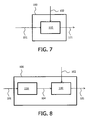
- Fig. 7 shows an embodiment of a send effect device comprising adapting send effect processing applied to the input signal 101
- Fig. 8 shows an embodiment of a send effect device comprising adapting an output signal itself in dependence of parameters.
- the send effect processing circuit 110 of Fig. 7 has an additional input to which the parameters 102 are provided.
- the send effect processing itself is adapted to include the adapting of the input signal 101 e.g. by means of scaling.
- the output adaptation circuit 130 is fed with a signal resulting from applying the send effect to the input signal 101 in the send effect processing circuit 110.
- the output adaptation circuit 130 has as an input also the parameters 102. It should be clear for a person skilled in art how the send effect processing circuit 110 should be adapted or what the output adaptation circuit should do.
- the gains may be delayed and/or adjusted to incorporate e.g. time-spreading effect which is relevant for the reverberation effect.
- the input signal and the parameters are the downmix signal and the parameters, respectively, in accordance with the MPEG Surround standard.
- the relation of the input signal to the downmix and the parameters to the spatial parameters of MPEG Surround should be clear based on the description of the figures.
- Fig. 9 shows an embodiment of a binaural decoder comprising a binaural renderer in parallel with the send effect device. This figure differs from Fig. 1 by the send device 100 having additional input for providing the parameters 102.
Landscapes
- Physics & Mathematics (AREA)
- Engineering & Computer Science (AREA)
- Acoustics & Sound (AREA)
- Signal Processing (AREA)
- Stereophonic System (AREA)
Priority Applications (2)
| Application Number | Priority Date | Filing Date | Title |
|---|---|---|---|
| EP09796455A EP2380364B1 (en) | 2008-12-22 | 2009-12-16 | Generating an output signal by send effect processing |
| PL09796455T PL2380364T3 (pl) | 2008-12-22 | 2009-12-16 | Wytwarzanie sygnału wyjściowego za pomocą przetwarzania wysyłania efektu |
Applications Claiming Priority (3)
| Application Number | Priority Date | Filing Date | Title |
|---|---|---|---|
| EP08172499 | 2008-12-22 | ||
| PCT/IB2009/055779 WO2010073187A1 (en) | 2008-12-22 | 2009-12-16 | Generating an output signal by send effect processing |
| EP09796455A EP2380364B1 (en) | 2008-12-22 | 2009-12-16 | Generating an output signal by send effect processing |
Publications (2)
| Publication Number | Publication Date |
|---|---|
| EP2380364A1 EP2380364A1 (en) | 2011-10-26 |
| EP2380364B1 true EP2380364B1 (en) | 2012-10-17 |
Family
ID=41663789
Family Applications (1)
| Application Number | Title | Priority Date | Filing Date |
|---|---|---|---|
| EP09796455A Active EP2380364B1 (en) | 2008-12-22 | 2009-12-16 | Generating an output signal by send effect processing |
Country Status (8)
| Country | Link |
|---|---|
| US (1) | US9591424B2 (enExample) |
| EP (1) | EP2380364B1 (enExample) |
| JP (1) | JP5679340B2 (enExample) |
| KR (1) | KR101595995B1 (enExample) |
| CN (1) | CN102265647B (enExample) |
| PL (1) | PL2380364T3 (enExample) |
| RU (1) | RU2011130551A (enExample) |
| WO (1) | WO2010073187A1 (enExample) |
Families Citing this family (3)
| Publication number | Priority date | Publication date | Assignee | Title |
|---|---|---|---|---|
| EP2523472A1 (en) | 2011-05-13 | 2012-11-14 | Fraunhofer-Gesellschaft zur Förderung der angewandten Forschung e.V. | Apparatus and method and computer program for generating a stereo output signal for providing additional output channels |
| JP6001814B1 (ja) | 2013-08-28 | 2016-10-05 | ドルビー ラボラトリーズ ライセンシング コーポレイション | ハイブリッドの波形符号化およびパラメトリック符号化発話向上 |
| CN115206332B (zh) * | 2021-04-12 | 2025-09-16 | 炬芯科技股份有限公司 | 一种音效的处理方法、装置、电子设备及存储介质 |
Family Cites Families (13)
| Publication number | Priority date | Publication date | Assignee | Title |
|---|---|---|---|---|
| CN1236649C (zh) * | 2002-07-17 | 2006-01-11 | 矽统科技股份有限公司 | 回响音效处理器 |
| US7634092B2 (en) * | 2004-10-14 | 2009-12-15 | Dolby Laboratories Licensing Corporation | Head related transfer functions for panned stereo audio content |
| WO2006060279A1 (en) * | 2004-11-30 | 2006-06-08 | Agere Systems Inc. | Parametric coding of spatial audio with object-based side information |
| EP1906706B1 (en) * | 2005-07-15 | 2009-11-25 | Panasonic Corporation | Audio decoder |
| RU2419249C2 (ru) * | 2005-09-13 | 2011-05-20 | Кониклейке Филипс Электроникс Н.В. | Аудиокодирование |
| WO2007080211A1 (en) * | 2006-01-09 | 2007-07-19 | Nokia Corporation | Decoding of binaural audio signals |
| WO2007080225A1 (en) * | 2006-01-09 | 2007-07-19 | Nokia Corporation | Decoding of binaural audio signals |
| BRPI0621485B1 (pt) | 2006-03-24 | 2020-01-14 | Dolby Int Ab | decodificador e método para derivar sinal de down mix de fone de ouvido, decodificador para derivar sinal de down mix estéreo espacial, receptor, método de recepção, reprodutor de áudio e método de reprodução de áudio |
| US8027479B2 (en) * | 2006-06-02 | 2011-09-27 | Coding Technologies Ab | Binaural multi-channel decoder in the context of non-energy conserving upmix rules |
| MX2009007412A (es) * | 2007-01-10 | 2009-07-17 | Koninkl Philips Electronics Nv | Decodificador de audio. |
| KR20080073925A (ko) * | 2007-02-07 | 2008-08-12 | 삼성전자주식회사 | 파라메트릭 부호화된 오디오 신호를 복호화하는 방법 및장치 |
| US7782235B1 (en) * | 2007-04-30 | 2010-08-24 | V Corp Technologies, Inc. | Adaptive mismatch compensators and methods for mismatch compensation |
| CA2820208C (en) | 2008-07-31 | 2015-10-27 | Fraunhofer-Gesellschaft Zur Forderung Der Angewandten Forschung E.V. | Signal generation for binaural signals |
-
2009
- 2009-12-16 WO PCT/IB2009/055779 patent/WO2010073187A1/en not_active Ceased
- 2009-12-16 KR KR1020117017068A patent/KR101595995B1/ko active Active
- 2009-12-16 US US13/140,476 patent/US9591424B2/en active Active
- 2009-12-16 RU RU2011130551/08A patent/RU2011130551A/ru unknown
- 2009-12-16 EP EP09796455A patent/EP2380364B1/en active Active
- 2009-12-16 JP JP2011541695A patent/JP5679340B2/ja active Active
- 2009-12-16 CN CN200980151965.8A patent/CN102265647B/zh active Active
- 2009-12-16 PL PL09796455T patent/PL2380364T3/pl unknown
Also Published As
| Publication number | Publication date |
|---|---|
| JP5679340B2 (ja) | 2015-03-04 |
| CN102265647A (zh) | 2011-11-30 |
| KR101595995B1 (ko) | 2016-02-22 |
| CN102265647B (zh) | 2015-05-20 |
| WO2010073187A1 (en) | 2010-07-01 |
| US20110249758A1 (en) | 2011-10-13 |
| JP2012513700A (ja) | 2012-06-14 |
| KR20110112376A (ko) | 2011-10-12 |
| EP2380364A1 (en) | 2011-10-26 |
| US9591424B2 (en) | 2017-03-07 |
| RU2011130551A (ru) | 2013-01-27 |
| PL2380364T3 (pl) | 2013-03-29 |
Similar Documents
| Publication | Publication Date | Title |
|---|---|---|
| US12131744B2 (en) | Audio encoding and decoding using presentation transform parameters | |
| RU2509442C2 (ru) | Способ и устройство для применения реверберации к многоканальному звуковому сигналу с использованием параметров пространственных меток | |
| RU2586851C2 (ru) | Устройство для формирования улучшенного сигнала микширования с понижением, способ формирования улучшенного сигнала микширования с понижением и компьютерная программа | |
| EP2524370B1 (en) | Extraction of a direct/ambience signal from a downmix signal and spatial parametric information | |
| KR101858479B1 (ko) | 제 1 및 제 2 입력 채널들을 적어도 하나의 출력 채널에 매핑하기 위한 장치 및 방법 | |
| US8280743B2 (en) | Channel reconfiguration with side information | |
| EP2751803B1 (en) | Audio object encoding and decoding | |
| CN103489449B (zh) | 音频信号译码器、提供上混信号表示型态的方法 | |
| JP2012516596A (ja) | ダウンミックスオーディオ信号をアップミックスするためのアップミキサー、方法、および、コンピュータ・プログラム | |
| EP2380364B1 (en) | Generating an output signal by send effect processing | |
| HK40097425A (en) | Audio encoding and decoding using presentation transform parameters | |
| HK1257673B (en) | Audio encoding and decoding using presentation transform parameters | |
| EA042232B1 (ru) | Кодирование и декодирование звука с использованием параметров преобразования представления | |
| HK1178307B (en) | Extraction of a direct/ambience signal from a downmix signal and spatial parametric information | |
| HK1178307A (en) | Extraction of a direct/ambience signal from a downmix signal and spatial parametric information | |
| HK1146975A1 (en) | Binaural multi-channel decoder in the context of non-energy-conserving upmix rules | |
| HK1146975B (en) | Binaural multi-channel decoder in the context of non-energy-conserving upmix rules |
Legal Events
| Date | Code | Title | Description |
|---|---|---|---|
| PUAI | Public reference made under article 153(3) epc to a published international application that has entered the european phase |
Free format text: ORIGINAL CODE: 0009012 |
|
| 17P | Request for examination filed |
Effective date: 20110722 |
|
| AK | Designated contracting states |
Kind code of ref document: A1 Designated state(s): AT BE BG CH CY CZ DE DK EE ES FI FR GB GR HR HU IE IS IT LI LT LU LV MC MK MT NL NO PL PT RO SE SI SK SM TR |
|
| 17Q | First examination report despatched |
Effective date: 20111201 |
|
| DAX | Request for extension of the european patent (deleted) | ||
| GRAP | Despatch of communication of intention to grant a patent |
Free format text: ORIGINAL CODE: EPIDOSNIGR1 |
|
| GRAS | Grant fee paid |
Free format text: ORIGINAL CODE: EPIDOSNIGR3 |
|
| GRAA | (expected) grant |
Free format text: ORIGINAL CODE: 0009210 |
|
| AK | Designated contracting states |
Kind code of ref document: B1 Designated state(s): AT BE BG CH CY CZ DE DK EE ES FI FR GB GR HR HU IE IS IT LI LT LU LV MC MK MT NL NO PL PT RO SE SI SK SM TR |
|
| REG | Reference to a national code |
Ref country code: GB Ref legal event code: FG4D |
|
| REG | Reference to a national code |
Ref country code: CH Ref legal event code: EP |
|
| REG | Reference to a national code |
Ref country code: IE Ref legal event code: FG4D |
|
| REG | Reference to a national code |
Ref country code: AT Ref legal event code: REF Ref document number: 580354 Country of ref document: AT Kind code of ref document: T Effective date: 20121115 |
|
| REG | Reference to a national code |
Ref country code: DE Ref legal event code: R084 Ref document number: 602009010543 Country of ref document: DE |
|
| REG | Reference to a national code |
Ref country code: DE Ref legal event code: R096 Ref document number: 602009010543 Country of ref document: DE Effective date: 20121206 |
|
| REG | Reference to a national code |
Ref country code: DE Ref legal event code: R084 Ref document number: 602009010543 Country of ref document: DE Effective date: 20121124 |
|
| REG | Reference to a national code |
Ref country code: AT Ref legal event code: MK05 Ref document number: 580354 Country of ref document: AT Kind code of ref document: T Effective date: 20121017 |
|
| REG | Reference to a national code |
Ref country code: NL Ref legal event code: VDEP Effective date: 20121017 |
|
| REG | Reference to a national code |
Ref country code: LT Ref legal event code: MG4D |
|
| REG | Reference to a national code |
Ref country code: PL Ref legal event code: T3 |
|
| PG25 | Lapsed in a contracting state [announced via postgrant information from national office to epo] |
Ref country code: NL Free format text: LAPSE BECAUSE OF FAILURE TO SUBMIT A TRANSLATION OF THE DESCRIPTION OR TO PAY THE FEE WITHIN THE PRESCRIBED TIME-LIMIT Effective date: 20121017 Ref country code: NO Free format text: LAPSE BECAUSE OF FAILURE TO SUBMIT A TRANSLATION OF THE DESCRIPTION OR TO PAY THE FEE WITHIN THE PRESCRIBED TIME-LIMIT Effective date: 20130117 Ref country code: SE Free format text: LAPSE BECAUSE OF FAILURE TO SUBMIT A TRANSLATION OF THE DESCRIPTION OR TO PAY THE FEE WITHIN THE PRESCRIBED TIME-LIMIT Effective date: 20121017 Ref country code: HR Free format text: LAPSE BECAUSE OF FAILURE TO SUBMIT A TRANSLATION OF THE DESCRIPTION OR TO PAY THE FEE WITHIN THE PRESCRIBED TIME-LIMIT Effective date: 20121017 Ref country code: LT Free format text: LAPSE BECAUSE OF FAILURE TO SUBMIT A TRANSLATION OF THE DESCRIPTION OR TO PAY THE FEE WITHIN THE PRESCRIBED TIME-LIMIT Effective date: 20121017 Ref country code: IS Free format text: LAPSE BECAUSE OF FAILURE TO SUBMIT A TRANSLATION OF THE DESCRIPTION OR TO PAY THE FEE WITHIN THE PRESCRIBED TIME-LIMIT Effective date: 20130217 Ref country code: FI Free format text: LAPSE BECAUSE OF FAILURE TO SUBMIT A TRANSLATION OF THE DESCRIPTION OR TO PAY THE FEE WITHIN THE PRESCRIBED TIME-LIMIT Effective date: 20121017 |
|
| PG25 | Lapsed in a contracting state [announced via postgrant information from national office to epo] |
Ref country code: BE Free format text: LAPSE BECAUSE OF FAILURE TO SUBMIT A TRANSLATION OF THE DESCRIPTION OR TO PAY THE FEE WITHIN THE PRESCRIBED TIME-LIMIT Effective date: 20121017 Ref country code: LV Free format text: LAPSE BECAUSE OF FAILURE TO SUBMIT A TRANSLATION OF THE DESCRIPTION OR TO PAY THE FEE WITHIN THE PRESCRIBED TIME-LIMIT Effective date: 20121017 Ref country code: PT Free format text: LAPSE BECAUSE OF FAILURE TO SUBMIT A TRANSLATION OF THE DESCRIPTION OR TO PAY THE FEE WITHIN THE PRESCRIBED TIME-LIMIT Effective date: 20130218 Ref country code: SI Free format text: LAPSE BECAUSE OF FAILURE TO SUBMIT A TRANSLATION OF THE DESCRIPTION OR TO PAY THE FEE WITHIN THE PRESCRIBED TIME-LIMIT Effective date: 20121017 Ref country code: GR Free format text: LAPSE BECAUSE OF FAILURE TO SUBMIT A TRANSLATION OF THE DESCRIPTION OR TO PAY THE FEE WITHIN THE PRESCRIBED TIME-LIMIT Effective date: 20130118 |
|
| PG25 | Lapsed in a contracting state [announced via postgrant information from national office to epo] |
Ref country code: AT Free format text: LAPSE BECAUSE OF FAILURE TO SUBMIT A TRANSLATION OF THE DESCRIPTION OR TO PAY THE FEE WITHIN THE PRESCRIBED TIME-LIMIT Effective date: 20121017 |
|
| PG25 | Lapsed in a contracting state [announced via postgrant information from national office to epo] |
Ref country code: EE Free format text: LAPSE BECAUSE OF FAILURE TO SUBMIT A TRANSLATION OF THE DESCRIPTION OR TO PAY THE FEE WITHIN THE PRESCRIBED TIME-LIMIT Effective date: 20121017 Ref country code: CZ Free format text: LAPSE BECAUSE OF FAILURE TO SUBMIT A TRANSLATION OF THE DESCRIPTION OR TO PAY THE FEE WITHIN THE PRESCRIBED TIME-LIMIT Effective date: 20121017 Ref country code: MC Free format text: LAPSE BECAUSE OF NON-PAYMENT OF DUE FEES Effective date: 20121231 Ref country code: SK Free format text: LAPSE BECAUSE OF FAILURE TO SUBMIT A TRANSLATION OF THE DESCRIPTION OR TO PAY THE FEE WITHIN THE PRESCRIBED TIME-LIMIT Effective date: 20121017 Ref country code: DK Free format text: LAPSE BECAUSE OF FAILURE TO SUBMIT A TRANSLATION OF THE DESCRIPTION OR TO PAY THE FEE WITHIN THE PRESCRIBED TIME-LIMIT Effective date: 20121017 Ref country code: BG Free format text: LAPSE BECAUSE OF FAILURE TO SUBMIT A TRANSLATION OF THE DESCRIPTION OR TO PAY THE FEE WITHIN THE PRESCRIBED TIME-LIMIT Effective date: 20130117 |
|
| PLBE | No opposition filed within time limit |
Free format text: ORIGINAL CODE: 0009261 |
|
| STAA | Information on the status of an ep patent application or granted ep patent |
Free format text: STATUS: NO OPPOSITION FILED WITHIN TIME LIMIT |
|
| PG25 | Lapsed in a contracting state [announced via postgrant information from national office to epo] |
Ref country code: RO Free format text: LAPSE BECAUSE OF FAILURE TO SUBMIT A TRANSLATION OF THE DESCRIPTION OR TO PAY THE FEE WITHIN THE PRESCRIBED TIME-LIMIT Effective date: 20121017 Ref country code: IT Free format text: LAPSE BECAUSE OF FAILURE TO SUBMIT A TRANSLATION OF THE DESCRIPTION OR TO PAY THE FEE WITHIN THE PRESCRIBED TIME-LIMIT Effective date: 20121017 |
|
| 26N | No opposition filed |
Effective date: 20130718 |
|
| REG | Reference to a national code |
Ref country code: IE Ref legal event code: MM4A |
|
| PG25 | Lapsed in a contracting state [announced via postgrant information from national office to epo] |
Ref country code: IE Free format text: LAPSE BECAUSE OF NON-PAYMENT OF DUE FEES Effective date: 20121216 Ref country code: ES Free format text: LAPSE BECAUSE OF FAILURE TO SUBMIT A TRANSLATION OF THE DESCRIPTION OR TO PAY THE FEE WITHIN THE PRESCRIBED TIME-LIMIT Effective date: 20130128 |
|
| REG | Reference to a national code |
Ref country code: DE Ref legal event code: R097 Ref document number: 602009010543 Country of ref document: DE Effective date: 20130718 |
|
| PG25 | Lapsed in a contracting state [announced via postgrant information from national office to epo] |
Ref country code: CY Free format text: LAPSE BECAUSE OF FAILURE TO SUBMIT A TRANSLATION OF THE DESCRIPTION OR TO PAY THE FEE WITHIN THE PRESCRIBED TIME-LIMIT Effective date: 20121017 Ref country code: MT Free format text: LAPSE BECAUSE OF FAILURE TO SUBMIT A TRANSLATION OF THE DESCRIPTION OR TO PAY THE FEE WITHIN THE PRESCRIBED TIME-LIMIT Effective date: 20121017 |
|
| REG | Reference to a national code |
Ref country code: DE Ref legal event code: R082 Ref document number: 602009010543 Country of ref document: DE Representative=s name: MEISSNER, BOLTE & PARTNER GBR, DE |
|
| REG | Reference to a national code |
Ref country code: DE Ref legal event code: R082 Ref document number: 602009010543 Country of ref document: DE Representative=s name: MEISSNER BOLTE PATENTANWAELTE RECHTSANWAELTE P, DE Effective date: 20140328 Ref country code: DE Ref legal event code: R082 Ref document number: 602009010543 Country of ref document: DE Representative=s name: MEISSNER, BOLTE & PARTNER GBR, DE Effective date: 20140328 Ref country code: DE Ref legal event code: R081 Ref document number: 602009010543 Country of ref document: DE Owner name: KONINKLIJKE PHILIPS N.V., NL Free format text: FORMER OWNER: KONINKLIJKE PHILIPS ELECTRONICS N.V., EINDHOVEN, NL Effective date: 20140328 |
|
| PG25 | Lapsed in a contracting state [announced via postgrant information from national office to epo] |
Ref country code: LU Free format text: LAPSE BECAUSE OF NON-PAYMENT OF DUE FEES Effective date: 20121216 Ref country code: SM Free format text: LAPSE BECAUSE OF FAILURE TO SUBMIT A TRANSLATION OF THE DESCRIPTION OR TO PAY THE FEE WITHIN THE PRESCRIBED TIME-LIMIT Effective date: 20121017 |
|
| PG25 | Lapsed in a contracting state [announced via postgrant information from national office to epo] |
Ref country code: HU Free format text: LAPSE BECAUSE OF FAILURE TO SUBMIT A TRANSLATION OF THE DESCRIPTION OR TO PAY THE FEE WITHIN THE PRESCRIBED TIME-LIMIT Effective date: 20091216 |
|
| REG | Reference to a national code |
Ref country code: CH Ref legal event code: PL |
|
| PG25 | Lapsed in a contracting state [announced via postgrant information from national office to epo] |
Ref country code: LI Free format text: LAPSE BECAUSE OF NON-PAYMENT OF DUE FEES Effective date: 20131231 Ref country code: CH Free format text: LAPSE BECAUSE OF NON-PAYMENT OF DUE FEES Effective date: 20131231 |
|
| REG | Reference to a national code |
Ref country code: FR Ref legal event code: CD Owner name: KONINKLIJKE PHILIPS ELECTRONICS N.V., NL Effective date: 20141126 Ref country code: FR Ref legal event code: CA Effective date: 20141126 |
|
| PG25 | Lapsed in a contracting state [announced via postgrant information from national office to epo] |
Ref country code: MK Free format text: LAPSE BECAUSE OF FAILURE TO SUBMIT A TRANSLATION OF THE DESCRIPTION OR TO PAY THE FEE WITHIN THE PRESCRIBED TIME-LIMIT Effective date: 20121017 |
|
| REG | Reference to a national code |
Ref country code: FR Ref legal event code: PLFP Year of fee payment: 7 |
|
| REG | Reference to a national code |
Ref country code: FR Ref legal event code: PLFP Year of fee payment: 8 |
|
| REG | Reference to a national code |
Ref country code: FR Ref legal event code: PLFP Year of fee payment: 9 |
|
| PGFP | Annual fee paid to national office [announced via postgrant information from national office to epo] |
Ref country code: PL Payment date: 20241206 Year of fee payment: 16 |
|
| PGFP | Annual fee paid to national office [announced via postgrant information from national office to epo] |
Ref country code: GB Payment date: 20241217 Year of fee payment: 16 |
|
| PGFP | Annual fee paid to national office [announced via postgrant information from national office to epo] |
Ref country code: FR Payment date: 20241227 Year of fee payment: 16 |
|
| PGFP | Annual fee paid to national office [announced via postgrant information from national office to epo] |
Ref country code: TR Payment date: 20241204 Year of fee payment: 16 |
|
| PGFP | Annual fee paid to national office [announced via postgrant information from national office to epo] |
Ref country code: DE Payment date: 20241227 Year of fee payment: 16 |