EP2379895B1 - Vortex-induced vibration (viv) suppression of riser arrays - Google Patents
Vortex-induced vibration (viv) suppression of riser arrays Download PDFInfo
- Publication number
- EP2379895B1 EP2379895B1 EP09839028.9A EP09839028A EP2379895B1 EP 2379895 B1 EP2379895 B1 EP 2379895B1 EP 09839028 A EP09839028 A EP 09839028A EP 2379895 B1 EP2379895 B1 EP 2379895B1
- Authority
- EP
- European Patent Office
- Prior art keywords
- tubular
- structures
- tubular structures
- suppression devices
- viv
- Prior art date
- Legal status (The legal status is an assumption and is not a legal conclusion. Google has not performed a legal analysis and makes no representation as to the accuracy of the status listed.)
- Active
Links
Images



Classifications
-
- F—MECHANICAL ENGINEERING; LIGHTING; HEATING; WEAPONS; BLASTING
- F15—FLUID-PRESSURE ACTUATORS; HYDRAULICS OR PNEUMATICS IN GENERAL
- F15D—FLUID DYNAMICS, i.e. METHODS OR MEANS FOR INFLUENCING THE FLOW OF GASES OR LIQUIDS
- F15D1/00—Influencing flow of fluids
- F15D1/10—Influencing flow of fluids around bodies of solid material
-
- B—PERFORMING OPERATIONS; TRANSPORTING
- B63—SHIPS OR OTHER WATERBORNE VESSELS; RELATED EQUIPMENT
- B63B—SHIPS OR OTHER WATERBORNE VESSELS; EQUIPMENT FOR SHIPPING
- B63B21/00—Tying-up; Shifting, towing, or pushing equipment; Anchoring
- B63B21/50—Anchoring arrangements or methods for special vessels, e.g. for floating drilling platforms or dredgers
- B63B21/502—Anchoring arrangements or methods for special vessels, e.g. for floating drilling platforms or dredgers by means of tension legs
-
- E—FIXED CONSTRUCTIONS
- E21—EARTH OR ROCK DRILLING; MINING
- E21B—EARTH OR ROCK DRILLING; OBTAINING OIL, GAS, WATER, SOLUBLE OR MELTABLE MATERIALS OR A SLURRY OF MINERALS FROM WELLS
- E21B17/00—Drilling rods or pipes; Flexible drill strings; Kellies; Drill collars; Sucker rods; Cables; Casings; Tubings
- E21B17/01—Risers
-
- F—MECHANICAL ENGINEERING; LIGHTING; HEATING; WEAPONS; BLASTING
- F25—REFRIGERATION OR COOLING; COMBINED HEATING AND REFRIGERATION SYSTEMS; HEAT PUMP SYSTEMS; MANUFACTURE OR STORAGE OF ICE; LIQUEFACTION SOLIDIFICATION OF GASES
- F25J—LIQUEFACTION, SOLIDIFICATION OR SEPARATION OF GASES OR GASEOUS OR LIQUEFIED GASEOUS MIXTURES BY PRESSURE AND COLD TREATMENT OR BY BRINGING THEM INTO THE SUPERCRITICAL STATE
- F25J1/00—Processes or apparatus for liquefying or solidifying gases or gaseous mixtures
- F25J1/0002—Processes or apparatus for liquefying or solidifying gases or gaseous mixtures characterised by the fluid to be liquefied
- F25J1/0022—Hydrocarbons, e.g. natural gas
-
- F—MECHANICAL ENGINEERING; LIGHTING; HEATING; WEAPONS; BLASTING
- F25—REFRIGERATION OR COOLING; COMBINED HEATING AND REFRIGERATION SYSTEMS; HEAT PUMP SYSTEMS; MANUFACTURE OR STORAGE OF ICE; LIQUEFACTION SOLIDIFICATION OF GASES
- F25J—LIQUEFACTION, SOLIDIFICATION OR SEPARATION OF GASES OR GASEOUS OR LIQUEFIED GASEOUS MIXTURES BY PRESSURE AND COLD TREATMENT OR BY BRINGING THEM INTO THE SUPERCRITICAL STATE
- F25J1/00—Processes or apparatus for liquefying or solidifying gases or gaseous mixtures
- F25J1/02—Processes or apparatus for liquefying or solidifying gases or gaseous mixtures requiring the use of refrigeration, e.g. of helium or hydrogen ; Details and kind of the refrigeration system used; Integration with other units or processes; Controlling aspects of the process
- F25J1/0243—Start-up or control of the process; Details of the apparatus used; Details of the refrigerant compression system used
- F25J1/0257—Construction and layout of liquefaction equipments, e.g. valves, machines
- F25J1/0275—Construction and layout of liquefaction equipments, e.g. valves, machines adapted for special use of the liquefaction unit, e.g. portable or transportable devices
- F25J1/0277—Offshore use, e.g. during shipping
- F25J1/0278—Unit being stationary, e.g. on floating barge or fixed platform
-
- F—MECHANICAL ENGINEERING; LIGHTING; HEATING; WEAPONS; BLASTING
- F25—REFRIGERATION OR COOLING; COMBINED HEATING AND REFRIGERATION SYSTEMS; HEAT PUMP SYSTEMS; MANUFACTURE OR STORAGE OF ICE; LIQUEFACTION SOLIDIFICATION OF GASES
- F25J—LIQUEFACTION, SOLIDIFICATION OR SEPARATION OF GASES OR GASEOUS OR LIQUEFIED GASEOUS MIXTURES BY PRESSURE AND COLD TREATMENT OR BY BRINGING THEM INTO THE SUPERCRITICAL STATE
- F25J1/00—Processes or apparatus for liquefying or solidifying gases or gaseous mixtures
- F25J1/02—Processes or apparatus for liquefying or solidifying gases or gaseous mixtures requiring the use of refrigeration, e.g. of helium or hydrogen ; Details and kind of the refrigeration system used; Integration with other units or processes; Controlling aspects of the process
- F25J1/0243—Start-up or control of the process; Details of the apparatus used; Details of the refrigerant compression system used
- F25J1/0279—Compression of refrigerant or internal recycle fluid, e.g. kind of compressor, accumulator, suction drum etc.
- F25J1/0296—Removal of the heat of compression, e.g. within an inter- or afterstage-cooler against an ambient heat sink
- F25J1/0297—Removal of the heat of compression, e.g. within an inter- or afterstage-cooler against an ambient heat sink using an externally chilled fluid, e.g. chilled water
-
- B—PERFORMING OPERATIONS; TRANSPORTING
- B63—SHIPS OR OTHER WATERBORNE VESSELS; RELATED EQUIPMENT
- B63B—SHIPS OR OTHER WATERBORNE VESSELS; EQUIPMENT FOR SHIPPING
- B63B13/00—Conduits for emptying or ballasting; Self-bailing equipment; Scuppers
-
- B—PERFORMING OPERATIONS; TRANSPORTING
- B63—SHIPS OR OTHER WATERBORNE VESSELS; RELATED EQUIPMENT
- B63B—SHIPS OR OTHER WATERBORNE VESSELS; EQUIPMENT FOR SHIPPING
- B63B21/00—Tying-up; Shifting, towing, or pushing equipment; Anchoring
- B63B21/50—Anchoring arrangements or methods for special vessels, e.g. for floating drilling platforms or dredgers
- B63B21/502—Anchoring arrangements or methods for special vessels, e.g. for floating drilling platforms or dredgers by means of tension legs
- B63B2021/504—Anchoring arrangements or methods for special vessels, e.g. for floating drilling platforms or dredgers by means of tension legs comprising suppressors for vortex induced vibrations
-
- B—PERFORMING OPERATIONS; TRANSPORTING
- B63—SHIPS OR OTHER WATERBORNE VESSELS; RELATED EQUIPMENT
- B63J—AUXILIARIES ON VESSELS
- B63J2/00—Arrangements of ventilation, heating, cooling, or air-conditioning
- B63J2/12—Heating; Cooling
Definitions
- the present invention relates to systems and methods for reducing drag and/or vortex-induced vibration ("VIV") of a plurality of structures.
- VIV vortex-induced vibration
- Floating vessels may be used to liquify and gasify natural gas.
- Sea water may be used to cool or heat the natural gas. It may be desired to separate the water inlet from the water outlet due to the temperature differences.
- a plurality of risers may be used to collect or deposit water at a depth from the floating vessel. These risers may be exposed to VIV.
- Drilling for and/or producing hydrocarbons or the like from subterranean deposits which exist under a body of water exposes underwater drilling and production equipment to water currents and the possibility of VIV.
- Equipment exposed to VIV includes structures ranging from the smaller tubes of a riser system, anchoring tendons, or lateral pipelines to the larger underwater cylinders of the hull of a mini spar or spar floating production system (hereinafter "spar").
- the magnitude of the stresses on the riser pipe, tendons or spars may be generally a function of and increases with the velocity of the water current passing these structures and the length of the structure.
- the first kind of stress may be caused by vortex-induced alternating forces that vibrate the structure ("vortex-induced vibrations") in a direction mainly perpendicular to the direction of the current.
- vortex-induced vibrations When fluid flows past the structure, vortices may be alternately shed from each side of the structure. This produces a fluctuating force on the structure transverse to the current. If the frequency of this harmonic load is near one of the natural frequencies of the structure, large vibrations transverse to the current can occur. These vibrations can, depending on the stiffness and the strength of the structure and any welds, lead to unacceptably short fatigue lives.
- stresses caused by high current conditions in marine environments have been known to cause structures such as risers to break apart and fall to the ocean floor.
- the second type of stress may be caused by drag forces, which push the structure in the direction of the current due to the structure's resistance to fluid flow.
- the drag forces may be amplified by vortex-induced vibration of the structure. For instance, a riser pipe that is vibrating due to vortex shedding will generally disrupt the flow of water around it more than a stationary riser. This may result in more energy transfer from the current to the riser, and hence more drag.
- Devices used to reduce vibrations caused by vortex shedding from sub-sea structures may operate by modifying the boundary layer of the flow around the structure to prevent the correlation of vortex shedding along the length of the structure.
- Examples of such devices include sleeve-like devices such as helical strakes, shrouds, fairings and substantially cylindrical sleeves.
- VIV and/or drag reduction devices Elongated structures in wind or other flowing fluids can also encounter VIV and/or drag, comparable to that encountered in aquatic environments. Likewise, elongated structures with excessive VIV and/or drag forces that extend far above the ground can be difficult, expensive and dangerous to reach by human workers to install VIV and/or drag reduction devices.
- Fairings may be used to suppress VIV and reduce drag acting on a structure in a flowing fluid environment. Fairings may be defined by a chord to length ratio, where longer fairings have a higher ratio than shorter fairings. Long fairings are more effective than short fairings at resisting drag, but may be subject to instabilities. Short fairings are less subject to instabilities, but may have higher drag in a flowing fluid environment.
- U.S. Patent Number 6,223,672 discloses an ultrashort fairing for suppressing vortex-induced vibration in substantially cylindrical marine elements.
- the ultrashort falling has a leading edge substantially defined by the circular profile of the marine element for a distance following at least about 270 degrees thereabout and a pair of shaped sides departing from the circular profile of the marine riser and converging at a trailing edge.
- the ultrashort fairing has dimensions of thickness and chord length such that the chord to thickness ratio is between about 1.20 and 1.10.
- U.S. Patent Number 6,223,672 is herein incorporated by reference in its entirety.
- U.S. Patent Number 3,978,804 discloses a structure floating on a body of water, and particularly a structure for drilling or producing wells from below the water. Buoyant members support at least a part of the structure above the surface of the water. The structure is connected to anchors in the floor of the body of water by a series of parallel leg members. Each leg member is composed of a plurality of elongated members, such as large diameter pipe usually called risers. These risers are parallel. Vertically spaced spacers are provided along the risers of each leg to (1) maintain the risers a fixed distance apart and (2) change the natural or resonant frequency of the individual riser pipes to be greater than the flutter frequency caused by the motion of the water past the risers.
- U.S. Patent Number 3,978,804 is herein incorporated by reference in its entirety.
- U.S. Patent Number 6,089,022 discloses a system and a method for regasifing LNG aboard a carrier vessel before the re-vaporized natural gas is transferred to shore.
- the pressure of the LNG is boosted substantially while the LNG is in its liquid phase and before it is flowed through a vaporizer(s) which, in turn, is positioned aboard the vessel.
- Seawater taken from the body of water surrounding said vessel is flowed through the vaporizer to heat and vaporize the LNG back into natural gas before the natural gas is off-loaded to onshore facilities.
- U.S. Patent Number 6,089,022 is herein incorporated by reference in its entirety.
- U.S. Patent Number 6,832,875 discloses a floating plant for liquefying natural gas having a barge provided with a liquefaction plant, member for receiving natural gas and with member for storing and discharging liquefied natural gas.
- the liquefaction plant involves a heat exchange in which heat is removed when liquefying natural gas is transferred to water.
- the barge is further provided with a receptacle; an open-ended water intake conduit having an inlet; a connecting conduit extending from the outlet of the water intake conduit to the receptacle; a pump for transporting water from the receptacle to the heat exchanger and a water discharge system for discharging water removed from the heat exchanger.
- the connecting conduit has the shape of an inverted "U" of which the top is located above the receptacle.
- U.S. Patent Number 6,832,875 is herein incorporated by reference in its entirety.
- US 2008/044235 A1 discloses a deep draft semi submersible structure with at least three vertically oriented buoyant columns. Each of the vertically oriented buoyant columns have at least one bal- lasted compartment and the columns are spaced apart at a sufficient distance to reduce vortex induced vibration amplitude. There are at least two connecting structural sealed trusses connected to the columns below sea level, they are positioned to minimize hydrodynamic wave action on the trusses and to transfer shear loads between the columns while remaining transparent to wave and ocean current motion.
- WO 00/61433 A1 discloses a strake system for protecting a cylindrical marine element from vortex induced vibration.
- the strake system comprises at least two shell members forming a hollow cylinder defining a cylindrical hollow passage for receiving the marine element, the hollow cylinder being provided with a strake extending along the outer surface of the hollow cylinder so as to reduce vortex induced vibrations of the marine element.
- US 2004/253059 A1 discloses a semi-submersible floating platform for offshore drilling and/or production of petroleum product from the seabed.
- the platform has a central columnar buoyancy apparatus and at least one vertical riser passing through the buoyancy apparatus.
- Each riser has a lower portion that is horizontally restrained within the buoyancy apparatus below the center of gravity thereof.
- apparatus and methods for reducing VIV and/or drag on structures in flowing fluid environments which do not suffer from certain disadvantages of the prior art apparatus and methods; apparatus and methods for reducing VIV and/or drag on multiple structures in flowing fluid environments; apparatus and methods for reducing VIV and/or drag on a riser array or bundle.
- One aspect of the invention provides a system according to claim 1.
- Another aspect of the invention provides a process according to claim 10.
- Advantages of the invention may include one or more of the following: improved VIV reduction of a plurality of structures; improved drag reduction of a plurality of structures; lower cost VIV reduction; and/or VIV reduction of a plurality of structures with fewer VIV suppression devices.
- Figure 1 illustrates an example of a marine system.
- the marine system includes surface structure 102 near a water surface 104, for example a surface of the ocean.
- the surface structure may include a ship, a barge, a vessel, an FPSO (floating production storage and offloading), a TLP (tension leg platform), a spar, an offshore rig, an offshore platform, a floating plant, a floating liquefied natural gas plant, or other floating or surface structures as are known in the art.
- a plurality of tubular structures 106 are coupled with the surface structure.
- the tubular structures may be used in conjunction with providing cold water at depth to cool natural gas in a floating liquefied natural gas plant serving as the surface structure.
- the tubular structures may be connected to a marine riser tensioner, a swivel joint, a ball joint, or the like.
- a tubular structure has a circular or oval cross-section.
- a cross-section of a tubular structure need not be circular or oval, but can include other shapes such as, but not limited to, rectangular.
- tubular structures 106A, 106B are visible. More tubular structures may optionally be included, such as, for example, at least three, at least four, at least six, at least nine, or more.
- suitable tubular structures include, but are not limited to, cables, umbilicals, risers, marine risers, riser pipes, marine pipes, pipes, tubes, or the like, or combinations thereof.
- the structures may extend all the way to a seafloor 108, or only part way to the seafloor. In some cases, mud, crude, water, and/or other fluids or electricity or electrical signals may be conveyed through the structures.
- the tubular structures are physically connected together, or held in a position relative to one another, with one or more interconnected guide sleeves or other spacers 110A, 110B.
- the spacers connect or hold in position the tubular structures as an array, bundle, grouping, other ordered arrangement, or other joined plurality.
- the spacers may include a metal, plastic, or otherwise sufficiently strong material in a disc, plate, rectangle, interconnected polygonal bars, wheel and spoke shape, or other shape.
- the spacers may have holes or other openings therein. Each of the holes or openings may accommodate and have inserted therein one of the tubular structures.
- the spacers may help to keep the tubulars relatively close together, but separated so that they do not significantly strike into one another or otherwise damage one another.
- tubular structures may serve as a structural support for the spacers.
- a tubular structure serving as a structural support for a spacer may be connected (directly or indirectly) to the spacer.
- tubular structures in an array or grouping such tubular structures need not be connected to a spacer and in the case of a tubular structure having, for example, a circular or oval shape, may instead have an outer (outside) diameter (including or not including a VIV suppression device) less than a diameter of an opening in the spacer.
- the outer (outside) diameter of the tubular structure may be similar to a diameter of an opening so that the tubular structure or a VIV suppression device on a tubular structure and the spacer may be in contact (e.g., a force fit).
- VIV vortex-induced vibration
- VIV suppression devices may be used to help suppress the VIV.
- VIV suppression devices or structures suitable for implementing embodiments include, but are not limited to, strakes, fairings, Henning devices, shrouds, wake splitters, and other types of VIV suppression devices or structures.
- Suitable VIV suppression devices are disclosed in U.S. Patent Publication Number 2006/0021560 ; U.S. Patent Number 7,406,923 ; U.S. Patent Publication Number 2006/0280559 ; U.S. Patent Publication Number 2007/0003372 ; U.S. Patent Publication Number 2009/0242207 ; PCT Publication Number WO2007/149770 ; PCT Publication Number WO 2008/064104 ; U.S. Patent Publication Number 2010/0061809 ; U.S. Patent Number 5,410,979 ; U.S. Patent Number 5,410,979 ; U.S. Patent Number 5,421,413 ; U.S. Patent Number 6,179,524 ; U.S.
- Suitable methods for installing VIV suppression devices are disclosed in U.S. Patent Number 7,578,038 ; U.S. Patent Number 8,029,210 ; U.S. Patent Publication Number 2008/0056828 ; U.S. Patent Publication Number 2007/0125546 ; U.S. Patent Publication Number 2007/0140797 ; U.S. Patent Publication Number 2010/0014922 ; U.S. Patent Number 6,695,539 ; U.S. Patent Number 6,928,709 ; and U.S. Patent Number 6,994,492 ; which are herein incorporated by reference in their entirety.
- the VIV suppression devices may be installed on the tubular member (e.g. buoyancy material and riser) before or after the tubular member is placed in a body of water.
- the tubular member e.g. buoyancy material and riser
- the VIV suppression devices may have a clamshell configuration, and may be hinged with a closing mechanism opposite the hinge, for example a mechanism that can be operated with an ROV.
- VIV suppression devices may be provided with copper plates on their ends to allow them to weathervane with adjacent VIV suppression devices or collars.
- VIV suppression devices may be partially manufactured from copper.
- Figures 2A-2B show two common types of VIV suppression devices or structures. Each of these devices or structures is suitable for implementing one or more embodiments.
- Figure 2A is a cross-sectional top view illustrating one or more representative strakes 220 installed along a length of tubular structure 206 as VIV suppression device(s).
- the strake(s) may be helical strakes, which are helically wrapped or coiled around the tubular structure and may be described as connected thereto.
- Figure 2B is a cross-sectional top view illustrating a representative fairing 222 installed along a length of tubular structure 206 as a VIV suppression device and may be described as connected thereto.
- the fairing has nose 224 and tail 226.
- the fairing may swivel around the tubular structure based on the ocean current.
- the leftmost tubular structure 106A has one or more VIV suppression devices or structures 114A, 114B connected thereto therewith. Conventional collars (not shown) may be used to keep the VIV suppression devices from moving along the length of the tubular structures.
- the rightmost tubular structure 106B does not have any VIV suppression devices or structures coupled therewith.
- VIV suppression devices Omitting the VIV suppression devices from some of the tubular structures (so that only a subset of the tubular structures have the VIV suppression devices) may offer certain potential advantages. For one thing, providing the VIV suppression devices on all of the tubular structures tends to increase the overall equipment cost. For another thing, it tends to be more difficult, time consuming, and/or more expensive to install tubular structures with VIV suppression devices as compared to tubular structures without VIV suppression devices. The VIV suppression devices may tend to make the tubular structures more bulky, difficult to maneuver, difficult to align, and/or difficult to couple with the spacers. It likewise tends to be more difficult, time consuming, and/or more expensive to retrieve tubular structures with VIV suppression devices, such as, for example, for cleaning, inspection, and/or repair.
- tubular structures typically from about 20 percent to about 80 percent may have the VIV suppression devices coupled with them. Often, from about 30 percent to about 70 percent of the tubular structures may have the VIV suppression devices coupled with them. In some cases, from about 40 percent to 60 percent of the tubular structures may have the VIV suppression devices coupled with them.
- the coverage density (the length of the structure covered with VIV suppression devices compared to the total length) may be less than 1.
- the coverage density may also be expressed as a percentage of the tubular structure length, and may be less than 100 percent. Typically, the coverage density may range from about 50 percent to about 100 percent, for example from about 60 to about 90%.
- the number or percentage of tubular structures having VIV suppression devices may be decreased by increasing the coverage density of a selection of the tubular structures. In converse, if desired, the coverage density may be decreased by increasing the number or percentage of tubular structures having VIV suppression devices.
- Figures 3A-3H illustrate several different example approaches or configurations of VIV suppression devices connected with a subset of tubular structures of an array, bundle, group, or other plurality of tubular structures, according to various embodiments. These figures represent cross-sectional views taken along section line 3/4/5 of Figure 1 through spacer 110A and the plurality of tubular structures 106. The spacers couple the tubular structures together, or hold the tubular structures in position relative to one another, as arrays, bundles, groups, other ordered arrangements, or other coupled pluralities.
- FIG. 1 circles indicate tubular structures. It is to be appreciated that a tubular structure need not occupy an entire cross-sectional area of an opening in spacer 110A. Hatched circles indicate tubular structures that have VIV suppression devices coupled therewith. Un-hatched circles indicate tubular structures without VIV suppression devices. While Figures 3A-3H show different examples of VIV suppression devices connected with a subset of tubular structures of an array (e.g., less than all tubular structures), in another embodiment, VIV suppression devices may be connected to each of the tubular structures in the array. Any of the aforementioned VIV suppression devices are suitable.
- Figures 3A-3F illustrate approaches or configurations for nine tubular structures arranged in a three-by-three rectangular array, in this particular case a substantially square array.
- Figures 3A illustrates a first configuration in which only tubular structures at all four corner positions of the three-by-three rectangular array have VIV suppression devices connected thereto, according to one embodiment.
- the three-by-three rectangular array has tubular structures at four corner positions 106A, 106C, 106G, and 1061, respectively. These corner positions are referred to herein as upper left corner 106A, upper right corner 106C, lower left corner 106G, and lower right corner 1061.
- the array also has tubular structures at four central side positions 106B, 106D, 106F, and 106H, respectively. These central side positions are referred to herein as upper side 106B, lower side 106H, right side 106F, and left side 106D, respectively.
- the corner positions and the side positions in combination form a periphery of the array.
- the three-by-three rectangular array also has one tubular structure at a center position 106E.
- the four tubular structures at the four corner positions are the only tubular structures that have VIV suppression devices connected thereto. These four tubular structures help to suppress VIV for the entire array.
- this arrangement is robust and does not show very much sensitivity to the angle of an oncoming ocean current.
- the vortex shedding frequency for the tubular structures with the VIV suppression devices are often lower than that of the tubular structure without the VIV suppression devices.
- the VIV suppression devices may tend to help "detune” or reduce the excitation frequency of the VIV of the tubular structures relative to bare tubular structures. This may increase the 'frequency dissociation' of the array. These tubular structures with different frequencies will be less likely to couple their vibrations. As a result, vibration of the array may be reduced.
- the tubular structures that have the VIV suppression devices are substantially interspersed, interleaved, or otherwise staggered with other tubular structures that do not have VIV suppression devices coupled with them.
- On the periphery of the array only every other tubular structure has a VIV suppression device connected thereto. In such a staggered arrangement, adjacent tubular structures tend to have different excitation frequencies. As discussed, with such frequency dissociation the vibrations on these tubular structures are less likely to couple and the overall vibration of the array may be reduced.
- tubular structures In this configuration four out of nine or about 44 percent of the tubular structures include VIV suppression devices connected thereto. On the periphery, four out of eight or a higher percentage of 50 percent of the tubular structures have VIV suppression devices connected thereto.
- Figures 3B illustrates a second configuration in which only a tubular structure at a center position and tubular structures at all four corner positions of the array have VIV suppression devices connected thereto, according to one embodiment.
- This configuration is similar to the configuration of Figure 3A except that the tubular structure at the center position also has VIV suppression devices connected thereto.
- tubular structures with VIV suppression devices are substantially staggered with tubular structures without VIV suppression devices.
- tubular structures without VIV suppression devices are substantially staggered with tubular structures without VIV suppression devices.
- VIV suppression devices are only every other tubular structure. Such staggering may tend to increase the amount of frequency dissociation, which may also help to reduce damage due to VIV.
- Figures 3C illustrates a third configuration in which only tubular structures at four central side positions of the array have VIV suppression devices connected thereto, according to one example embodiment.
- This configuration is substantially opposite to the configuration of Figure 3A in that tubular structures at the sides positions instead of at the corner positions have VIV suppression devices.
- tubular structures with VIV suppression devices are substantially staggered with tubular structures without VIV suppression devices.
- tubular structures without VIV suppression devices are substantially staggered with tubular structures without VIV suppression devices.
- VIV suppression devices are only every other tubular structure. Such staggering may tend to increase the amount of frequency dissociation, which may also help to reduce damage due to VIV.
- Sufficient suppression or dampening may be achieved with even lower numbers or percentages of tubular structures having VIV suppression devices when a predominant ocean, river, or other flowing fluid current is known.
- the array may be aligned so that a higher percentage of the tubular structures having the VIV suppression devices are on a front row that faces the predominant ocean current.
- Figures 3D illustrates a fourth configuration in which only tubular structures at three corner positions of a front row of the array that would first experience a predominant ocean current have VIV suppression devices connected thereto, according to one example embodiment.
- This configuration is similar to the configuration of Figure 3A except that the tubular structure at the lower left corner position does not have VIV suppression devices.
- a 'predominant' ocean current is the average or most common ocean current including its average or most common direction.
- three out of nine, or about 33 percent of the tubular structures include VIV suppression devices coupled therewith.
- three out of eight, or a higher percentage of about 37 percent of the tubular structures include VIV suppression devices.
- On the front row three out of five, or an even higher percentage of about 60 percent of the tubular structures, have VIV suppression devices.
- the array is aligned so that the tubular structure at the upper right corner position first experiences the predominant ocean current before all other tubular structures.
- This tubular structure would tend to experience the ocean current at its highest velocity and would tend to have a relatively large amount of VIV.
- this tubular structure has one or more VIV suppression devices.
- a wake refers to a region of separated flow, in some cases turbulent, downstream of a solid body caused by flow of the fluid around the body. Average fluid velocity tends to be lower in a wake. As a result, these downstream tubular structures tend to experience lesser velocity ocean currents and tend to have less VIV. In addition, tubular structures in the wake of other tubular structures, and experiencing a lower velocity current, tend to have a lower vortex shedding frequencies and/or excitation frequencies. This adds frequency dissociation to the array, which helps to reduce vibrations.
- the tubular structure at the lower left corner position does not have one or more VIV suppression devices.
- This tubular structure is downstream from several upstream tubular structures and should tend to experience the ocean current at a relatively reduced velocity. This makes it a relatively good candidate to omit VIV suppression device(s).
- a tubular structure that would last experience a predominant ocean current, after all other tubular structures of the array may not have one or more VIV suppression device(s).
- Figures 3E illustrates a fifth configuration in which four tubular structures at positions on a front row of the array that would first experience a predominant ocean current have VIV suppression devices connected thereto, according to one example embodiment.
- arrows are used to indicate a predominant ocean current.
- the array is aligned so that the tubular structure at the upper right corner position first experiences the predominant ocean current. This alignment places more of the tubular structures in the wakes of upstream tubular structures.
- tubular structures on the top and right sides of the array constitute a front row that first experiences the predominant ocean current.
- all four of the tubular structures with VIV suppression devices are on the front row.
- Figures 3F illustrates a fifth configuration in which only one tubular structure on a front row of the array and three tubular structures at positions downstream from the front row have VIV suppression devices connected thereto, according to one example embodiment. This design relies more upon frequency dissociation than upon strong suppression on the front row.
- Five tubular structures on the top and right sides of the array constitute a front row that first experiences the predominant ocean current. In this case, only one tubular structure with VIV suppression devices is on the front row.
- the array is aligned so a tubular structure at the upper right corner position, which first experiences the predominant ocean current, has VIV suppression devices connected thereto. This alignment also places more of the tubular structures in the wakes of upstream tubular structures. Notice that the lower left tubular structure, which would last experience the predominant ocean current after all other tubular structures of the array, does not have a VIV suppression device(s).
- the three-by-three rectangular array of Figures 3A-3F is not required.
- the plurality of tubular structures may have various other numbers of tubular structures and/or various other shapes (e.g., circular, star, triangular, etc.).
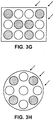
- Figure 3G illustrates another example configuration for twelve tubular structures arranged in a four-by-three rectangular array of twelve tubular structures, according to one example embodiment.
- a mix of a sufficient amount of front row suppression and a sufficient amount of frequency disassociation has been utilized.
- Arrows indicate a predominant ocean current.
- the array is aligned so that a tubular structure at the upper right corner position, which has VIV suppression devices coupled thereto, first experiences the predominant ocean current. This alignment also places more of the tubular structures in the wakes of upstream tubular structures.
- Non-rectangular arrays are also suitable.
- Figures 3H illustrates yet another example configuration for nine tubular structures arranged in a concentric array, according to one embodiment.
- the concentric array is circular.
- the array may be elliptical, oval, star shaped, triangular, etc.
- Arrows are used to indicate a predominant ocean current.
- the array is aligned so that a tubular structure that has VIV suppression devices coupled thereto first experiences the predominant ocean current.
- Tubular structures with VIV suppression devices are substantially staggered with tubular structures that lack VIV suppression devices. As before, on a periphery, only every other tubular structure has VIV suppression devices.
- the VIV suppression devices may optionally be conventional, and may be constructed of any suitable material conventionally used for VIV suppression devices.
- protective structures such as, for example, covers, caps, bumpers, or the like, may optionally be included on the VIV suppression devices to help prevent mechanical damage, if bumping or contact with a VIV suppression device were to occur.
- the protective structures may comprise pliable, elastic, or soft materials, such as, for example, rubber, plastic, foam, or the like.
- the ends of the sections of the VIV suppression devices may optionally be tapered to a smaller outside diameter than the outside diameter of a remainder of a section of a suppression device, which may facilitate installation and/or insertion through spacers.
- a tubular structure having a VIV suppression device installed thereon is inserted through an opening in a spacer, if an end of the suppression device that is to be initially inserted through the opening is tapered to a smaller outside diameter, it tends to be easier to align the suppression device/tubular structure with the opening and insert it into the opening.
- VIV suppression devices rather than using a single type and/or size of VIV suppression device, multiple, different types and/or sizes of VIV suppression devices may optionally be used, although this is not required.
- some of the subset of risers that have VIV suppression devices may have a first type of VIV suppression device (e.g., strakes), and others of the subset may have a second, different type of VIV suppression device (e.g., fairings).
- One strategy for using different types of VIV suppression devices might be to change the excitation frequencies of the risers and/or increase the frequency dissociation of the array.
- the different types may optionally be staggered relative to one another to provide additional frequency dissociation.
- tubular structures having a plurality of different outer diameters Another way of reducing vibrations is by using tubular structures having a plurality of different outer diameters. Accordingly, other embodiments pertain to a plurality of risers or other tubular structures, in which at least two of the risers or other tubular structures have different outer diameters. In one or more embodiments, at least three of the tubular structures may have different outer diameters.
- the diameter of a tubular structure affects its vortex shedding frequency and its VIV resonant frequency.
- tubular structures that have relatively larger hydrodynamic diameters will tend to have lower vortex shedding frequencies and lower excitation frequencies compared to tubular structures that have relatively smaller hydrodynamic diameters.
- including tubular structures with different outer diameters in a group, array, bundle, or other coupled plurality may help to "detune" the vibratory frequency of the group, array, bundle, or other plurality by increasing the level of frequency dissociation of the array.
- an upstream tubular structure typically has a higher shedding frequency than a downstream tubular structure that is in its wake.
- greater frequency dissociation is generally possible when a relatively larger diameter tubular structure is downstream of a relatively smaller diameter tubular structure.
- a tubular structure having a relatively larger diameter may be in a wake of, or downstream from, a structure having a relatively smaller diameter.
- an average diameter of a plurality of upstream tubular structures may be less than the average diameter of a plurality of downstream tubular structures in their wake.
- the largest diameters may range from 5 percent to 200 percent larger than the smallest diameters (expressed as a percentage of the smallest diameters). Often, the largest diameters may range from 10 percent to 150 percent larger than the smallest diameters. In cases, the largest diameters may range from 25 percent to 100 percent larger than the smallest diameters. However, the scope is not limited to any known difference between the diameters.
- a sheath or other coating may be included on the outside of a tubular structure in order to increase the outside diameter of the tubular structure.
- the term coating is not limited to a paint-like application process or the like but more broadly encompasses a material coupled with the outside of the tubular structure.
- coatings having a plurality of different thicknesses may be included on the outside of different tubular structures in order to increase the outside diameters of the tubular structures, and to provide a plurality of different outside diameters.
- the coatings may potentially serve a purpose other than to increase the diameter.
- the coatings may include thermal insulation to thermally insulate a fluid within the tubular structures.
- the coatings may include a buoyancy material.
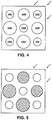
- Figure 4 illustrates an example approach or configuration of a plurality of tubular structures in which at least two, in this case at least three, of the tubular structures have different outer diameters, according to one or more embodiments.
- this figure is a cross-sectional view taken along section line 3/4/5 of Figure 1 through spacer 110A and the plurality of tubular structures 106.
- tubular structures are arranged in a three-by-three rectangular array.
- a tubular structure at a center position 106E and four tubular structures at four corner positions 106A, 106C, 106G, and 1061, all have a first outer diameter.
- a tubular structure 106D at a left center side position and a tubular structure 106H at a lower center side position both have a third outer diameter.
- the first outer diameter may be less than the second outer diameter
- the second outer diameter may be less than the third outer diameter.
- one or more of the tubular structures may have yet another fourth outer diameter different than the other three diameters.
- the larger diameter tubular structure 106D at the left side position is downstream from and in the wake of the smaller diameter tubular structure 106B at the upper side position.
- larger diameter tubular structure 106H at the lower side position is downstream from and in the wake of smaller diameter tubular structure 106F at the right side position.
- An average diameter of the upstream tubular structures e.g., 106B, 106C, and 106F
- FIG. 5 illustrates an example approach or configuration that is similar to that of Figure 4 except that, in addition to the different outer diameters, a subset of the tubular structures also have VIV suppression devices connected thereto, according to one or more embodiments.
- the hatched circles are tubular structures with VIV suppression devices.
- the un-hatched circles represent tubular structures without VIV suppression devices.
- the hatched circles are tubular structures without VIV suppression devices.
- the un-hatched circles represent tubular structures with VIV suppression devices.
- Both the different outer diameters and the VIV suppression devices may contribute to reducing vibrations.
- the greater the variation in the outer diameters the lesser the number of VIV suppression devices that would be needed to sufficiently reduce vibrations a particular implementation (including potentially none).
- the greater the number of VIV suppression devices the lesser the variation in the outer diameters needed to sufficiently reduce vibrations for a particular implementation (including potentially no variation).
- devices or structures may be part of or connected with an array or other associated or connected plurality of tubular structures. This may help to increase the overall suppression of the system. Examples of such devices include helical axial fins, axial non-helical fins, and circumferential fins.
- the fins or other devices or structures may be flexible or include a flexible material to further provide dampening.
- a coating that attracts marine growth may be added to the outside of the tubular structure to enhance dampening.
- a method of assembly may include initially installing a structural support tubular structure having one or more spacers connected therewith.
- a center tubular structure e.g., structure 106E
- a center tubular structure may be initially connected to one or more spacers along a length of the structural support (e.g., a length of multiple sections of the structural support).
- one or more of other tubular structures may be separately threaded, inserted, or otherwise introduced through openings in the spacers.
- the tubular structures may either have VIV suppression devices connected thereto before being introduced into the openings or the VIV suppression devices may be connected afterwards.
- some but not all, or a subset, of the tubular structures have VIV suppression devices connected thereto.
- a number of the tubular structures, in some cases at least three of the tubular structures, have different outer diameters.
- vibrations are suppressed with VIV suppression devices connected with only a subset of the tubular structures of a coupled or associated array or grouping.
- tubular structures with a number of outer diameters may be vibrated at a plurality of different frequencies.
- FIG. 6A illustrates an example of a marine system 600 in which embodiments may be implemented.
- the marine system includes a Floating Liquefied Natural Gas (FLNG) plant 602 on/in a surface of the ocean 104.
- FLNG Floating Liquefied Natural Gas
- the FLNG plant is one particular example of a surface structure.
- the FLNG plant may cool and liquefy natural gas, or alternatively heat and gasify LNG.
- One or more tubular structures of an array or grouping connected with FLNG plant 602 may be used to bring water from the ocean to the plant.
- riser arrays may be used as drilling riser arrays, production riser arrays, TLP tendons, etc.
- Marine system 600 in this embodiment, includes a number of tubular structures or risers 606 (e.g., nine tubular structures).
- the risers each have first ends and second ends.
- the first ends are connected to with the FLNG plant.
- the second ends project generally downward into the ocean but not necessarily to the seafloor.
- the second ends may have depths of around 130 to 170 meters, although this is not required.
- tubular structures 606 may deflect from vertical by around 40 degrees or so (not shown).
- tubular structures 606 may be connected with the FLNG plant through a swivel joint, a ball joint, a riser hanger, or other pivotable or hingeable coupling.
- Tubular structures 606 are physically associated or connected together with a plurality of guide sleeves or spacers 610A, 610B, 610C.
- the spacers may have openings through which respective ones of the tubular structures are disposed. In one embodiment, enough spacers may be provided to keep the tubular structures from striking into one another.
- tubular structures 606 may serve as water intake risers.
- the water intake risers may take in cold water 640 at depth, and convey the cold water upward to the FLNG plant.
- the cold water may be input to heat exchangers of the FLNG plant in order to cool natural gas to help liquefy the natural gas.
- the heated ocean water from the outlet of the heat exchangers may be discharged back into the ocean at the surface, or alternatively conveyed back to depth with a different riser or set of risers.
- filters may optionally be coupled to each of the bottoms of tubular structures 606.
- the filters may help to prevent soil, marine life (e.g., seaweed, algae, fish, etc.), and the like, from entering the tubular structures. Over time, the filters may tend to become clogged. It tends to be relatively difficult to clean the filters. For example, removing one or more tubular structures 606 from an array so that the filters may be cleaned tends to be costly, labor intensive, and/or time consuming.
- an array or grouping may include surplus water intake tubular structures (risers) so that the surplus water intake tubular structures may optionally be included to provide adequate water intake even after some of the filters clog.
- a tubular structure may be used until its filter clogs and then may be taken off line and a new tubular structure having a clean filter may be newly brought online.
- tubular structures with VIV suppression devices may not be used for water intake and may not have filters, but rather may be used primarily for VIV suppression, while bare tubular structures without VIV suppression devices may have filters and be used for water intake. These bare tubular structures tend to be easier to retrieve when their filters become clogged.
- Figure 6B shows an example approach or configuration for nine tubular structures (risers) arranged in a three-by-three rectangular array, according to one particular embodiment. This figure is a cross-sectional view taken along section line 6B of Figure 6A through the plurality of tubular structures 606.
- the array has eight tubular structures along the periphery and one riser at the center.
- the eight tubular structures along the periphery may serve as water intake risers to provide cold water to the FLNG plant.
- the tubular structure at the center may serve as a structural support structure (riser) for the spacers.
- the riser at the center may, or may not, convey water to the surface (i.e., may or may not serve as a water intake riser).
- the eight tubular structures along the periphery may have outer diameters of about 42 inches and wall thicknesses of about 1 inch, while the structural tubular structure at the center may have an outside diameter of about 24 inches and a thickness of about 0.75 inches.
- the eight tubular structures along the periphery may be equally spaced apart by a distance of about one outer diameter or about 42 inches.
- each of tubular structures may not be necessary to be in operation at any one time.
- one or more of the tubular structures may serve as a surplus water intake riser.
- tubular structures at all four corner positions of the three-by-three rectangular array have VIV suppression devices connected therewith.
- other arrangements or configurations disclosed herein may optionally be used.
- Speed range pertains to the current flow rate.
- Max rms A/D refers to the maximum motion magnitude (root-mean-square value) in the speed range tested and measures vibration. The lower the max rms A/D, the lower the amount of vibration on the risers.
- the scope of the invention is not limited to achieving any known particular amount of VIV suppression or dampening.
- the amount of VIV suppression or dampening appropriate for a particular implementation may vary widely from one implementation to another. This may be due in part to variation in ocean current, tubular length, materials of construction, amount of overdesign, and the like.
Landscapes
- Engineering & Computer Science (AREA)
- Mechanical Engineering (AREA)
- Physics & Mathematics (AREA)
- General Engineering & Computer Science (AREA)
- Thermal Sciences (AREA)
- Chemical & Material Sciences (AREA)
- Ocean & Marine Engineering (AREA)
- Combustion & Propulsion (AREA)
- Fluid Mechanics (AREA)
- Chemical Kinetics & Catalysis (AREA)
- General Chemical & Material Sciences (AREA)
- Oil, Petroleum & Natural Gas (AREA)
- Life Sciences & Earth Sciences (AREA)
- Geology (AREA)
- Mining & Mineral Resources (AREA)
- Environmental & Geological Engineering (AREA)
- General Life Sciences & Earth Sciences (AREA)
- Geochemistry & Mineralogy (AREA)
- Earth Drilling (AREA)
- Other Liquid Machine Or Engine Such As Wave Power Use (AREA)
- Vibration Prevention Devices (AREA)
- Buildings Adapted To Withstand Abnormal External Influences (AREA)
- Heat-Exchange Devices With Radiators And Conduit Assemblies (AREA)
- Pipeline Systems (AREA)
- Separation By Low-Temperature Treatments (AREA)
Description
- The present invention relates to systems and methods for reducing drag and/or vortex-induced vibration ("VIV") of a plurality of structures.
- Whenever a bluff body, such as a cylinder, experiences a current in a flowing fluid environment, it is possible for the body to experience vortex-induced vibration (VIV). These vibrations may be caused by oscillating dynamic forces on the surface, which can cause substantial vibrations of the structure, especially if the forcing frequency is at or near a structural natural frequency.
- Floating vessels may be used to liquify and gasify natural gas. Sea water may be used to cool or heat the natural gas. It may be desired to separate the water inlet from the water outlet due to the temperature differences. A plurality of risers may be used to collect or deposit water at a depth from the floating vessel. These risers may be exposed to VIV.
- Drilling for and/or producing hydrocarbons or the like from subterranean deposits which exist under a body of water exposes underwater drilling and production equipment to water currents and the possibility of VIV. Equipment exposed to VIV includes structures ranging from the smaller tubes of a riser system, anchoring tendons, or lateral pipelines to the larger underwater cylinders of the hull of a mini spar or spar floating production system (hereinafter "spar").
- The magnitude of the stresses on the riser pipe, tendons or spars may be generally a function of and increases with the velocity of the water current passing these structures and the length of the structure.
- It is noted that even moderate velocity currents in flowing fluid environments acting on linear structures can cause stresses. Such moderate or higher currents may be readily encountered when drilling for offshore oil and gas at greater depths in the ocean or in an ocean inlet or near a river mouth.
- There are generally two kinds of current-induced stresses in flowing fluid environments. The first kind of stress may be caused by vortex-induced alternating forces that vibrate the structure ("vortex-induced vibrations") in a direction mainly perpendicular to the direction of the current. When fluid flows past the structure, vortices may be alternately shed from each side of the structure. This produces a fluctuating force on the structure transverse to the current. If the frequency of this harmonic load is near one of the natural frequencies of the structure, large vibrations transverse to the current can occur. These vibrations can, depending on the stiffness and the strength of the structure and any welds, lead to unacceptably short fatigue lives. In fact, stresses caused by high current conditions in marine environments have been known to cause structures such as risers to break apart and fall to the ocean floor.
- The second type of stress may be caused by drag forces, which push the structure in the direction of the current due to the structure's resistance to fluid flow. The drag forces may be amplified by vortex-induced vibration of the structure. For instance, a riser pipe that is vibrating due to vortex shedding will generally disrupt the flow of water around it more than a stationary riser. This may result in more energy transfer from the current to the riser, and hence more drag.
- Many types of devices have been developed to reduce vibrations and/or drag of sub sea structures. Some of these devices used to reduce vibrations caused by vortex shedding from sub sea structures operate by stabilization of the wake. These methods include use of streamlined fairings, wake splitters and flags.
- Devices used to reduce vibrations caused by vortex shedding from sub-sea structures may operate by modifying the boundary layer of the flow around the structure to prevent the correlation of vortex shedding along the length of the structure. Examples of such devices include sleeve-like devices such as helical strakes, shrouds, fairings and substantially cylindrical sleeves.
- Elongated structures in wind or other flowing fluids can also encounter VIV and/or drag, comparable to that encountered in aquatic environments. Likewise, elongated structures with excessive VIV and/or drag forces that extend far above the ground can be difficult, expensive and dangerous to reach by human workers to install VIV and/or drag reduction devices.
- Fairings may be used to suppress VIV and reduce drag acting on a structure in a flowing fluid environment. Fairings may be defined by a chord to length ratio, where longer fairings have a higher ratio than shorter fairings. Long fairings are more effective than short fairings at resisting drag, but may be subject to instabilities. Short fairings are less subject to instabilities, but may have higher drag in a flowing fluid environment.
-
U.S. Patent Number 6,223,672 discloses an ultrashort fairing for suppressing vortex-induced vibration in substantially cylindrical marine elements. The ultrashort falling has a leading edge substantially defined by the circular profile of the marine element for a distance following at least about 270 degrees thereabout and a pair of shaped sides departing from the circular profile of the marine riser and converging at a trailing edge. The ultrashort fairing has dimensions of thickness and chord length such that the chord to thickness ratio is between about 1.20 and 1.10.U.S. Patent Number 6,223,672 is herein incorporated by reference in its entirety. -
U.S. Patent Number 3,978,804 discloses a structure floating on a body of water, and particularly a structure for drilling or producing wells from below the water. Buoyant members support at least a part of the structure above the surface of the water. The structure is connected to anchors in the floor of the body of water by a series of parallel leg members. Each leg member is composed of a plurality of elongated members, such as large diameter pipe usually called risers. These risers are parallel. Vertically spaced spacers are provided along the risers of each leg to (1) maintain the risers a fixed distance apart and (2) change the natural or resonant frequency of the individual riser pipes to be greater than the flutter frequency caused by the motion of the water past the risers.U.S. Patent Number 3,978,804 is herein incorporated by reference in its entirety. -
U.S. Patent Number 6,089,022 discloses a system and a method for regasifing LNG aboard a carrier vessel before the re-vaporized natural gas is transferred to shore. The pressure of the LNG is boosted substantially while the LNG is in its liquid phase and before it is flowed through a vaporizer(s) which, in turn, is positioned aboard the vessel. Seawater taken from the body of water surrounding said vessel is flowed through the vaporizer to heat and vaporize the LNG back into natural gas before the natural gas is off-loaded to onshore facilities.U.S. Patent Number 6,089,022 is herein incorporated by reference in its entirety. -
U.S. Patent Number 6,832,875 discloses a floating plant for liquefying natural gas having a barge provided with a liquefaction plant, member for receiving natural gas and with member for storing and discharging liquefied natural gas. The liquefaction plant involves a heat exchange in which heat is removed when liquefying natural gas is transferred to water. The barge is further provided with a receptacle; an open-ended water intake conduit having an inlet; a connecting conduit extending from the outlet of the water intake conduit to the receptacle; a pump for transporting water from the receptacle to the heat exchanger and a water discharge system for discharging water removed from the heat exchanger. The connecting conduit has the shape of an inverted "U" of which the top is located above the receptacle.U.S. Patent Number 6,832,875 is herein incorporated by reference in its entirety. -
US 2008/044235 A1 discloses a deep draft semi submersible structure with at least three vertically oriented buoyant columns. Each of the vertically oriented buoyant columns have at least one bal- lasted compartment and the columns are spaced apart at a sufficient distance to reduce vortex induced vibration amplitude. There are at least two connecting structural sealed trusses connected to the columns below sea level, they are positioned to minimize hydrodynamic wave action on the trusses and to transfer shear loads between the columns while remaining transparent to wave and ocean current motion. -
WO 00/61433 A1 - Yiannis Constantinides ET AL: "OMAE2006-92674 ANALYSIS OF TURBULENT FLOWS AND VIV OF TRUSS SPAR RISERS", 1 January 2006 (2006-01-01), is directed to complex flows through riser arrays, such as the case of risers located in the truss section of a truss spar. In this study, a full scale truss spar with vertical risers is modeled using CFD. The VIV response of the risers is predicted and the effect of risers is correctly captured and compared with experiments.
- DON ALLEN ET AL: "Performance Comparisons of Helical Strakes for VIV Suppression of Risers and Tendons", PROCEEDINGS OF OFFSHORE TECHNOLOGY CONFERENCE, 1 January 2004 (2004-01-01), pages 1-10, presents experimental results for various helical strake geometries and discusses their performance coefficients and responses. Experimental results from the presence of surface roughness and/or interference are also presented.
-
US 2004/253059 A1 discloses a semi-submersible floating platform for offshore drilling and/or production of petroleum product from the seabed. The platform has a central columnar buoyancy apparatus and at least one vertical riser passing through the buoyancy apparatus. Each riser has a lower portion that is horizontally restrained within the buoyancy apparatus below the center of gravity thereof. - There are needs in the art for one or more of the following: apparatus and methods for reducing VIV and/or drag on structures in flowing fluid environments, which do not suffer from certain disadvantages of the prior art apparatus and methods; apparatus and methods for reducing VIV and/or drag on multiple structures in flowing fluid environments; apparatus and methods for reducing VIV and/or drag on a riser array or bundle.
- These and other needs in the art will become apparent to those of skill in the art upon review of this specification, including its drawings and claims.
- One aspect of the invention provides a system according to claim 1.
- Another aspect of the invention provides a process according to claim 10.
- Versions of the system and process described herein falling outside the scope of the claims do not form part of the invention but represent background art that is useful for understanding the invention.
- Advantages of the invention may include one or more of the following: improved VIV reduction of a plurality of structures; improved drag reduction of a plurality of structures; lower cost VIV reduction; and/or VIV reduction of a plurality of structures with fewer VIV suppression devices.
- These and other aspects of the invention will become apparent to those of skill in the art upon review of this specification, including its drawings and claims.
- The invention may best be understood by referring to the following description and accompanying drawings that are used to illustrate embodiments of the invention. In the drawings:
-
Figure 1 illustrates an example of a marine system. -
Figure 2A is a cross-sectional top view illustrating one or more representative strakes installed along a length of tubular structure as VIV suppression device(s). -
Figure 2B is a cross-sectional top view illustrating a representative fairing installed along a length of tubular structure as a VIV suppression device. -
Figures 3A-3H illustrate several different examplary approaches or configurations for coupling VIV suppression devices with only a subset of tubular structures, according to various embodiments. -
Figure 4 illustrates an examplary approach or configuration of a plurality of tubular structures in which at least two, in this case at least three, of the tubular structures have different outer diameters, according to one or more embodiments. -
Figure 5 illustrates an example approach or configuration that is similar to that ofFigure 4 except that, in addition to the different outer diameters, a subset of the tubular structures also have VIV suppression devices coupled therewith, according to one or more embodiments. -
Figure 6A illustrates an example of a marine system including a Floating Liquified Natural Gas (FLNG) plant, in which embodiments may be implemented. -
Figure 6B shows an example approach or configuration for a Floating Liquified Natural Gas (FLNG) plant in which nine tubular structures are arranged in a three-by-three rectangular array, according to one particular embodiment. - In the following description, numerous specific details are set forth. However, it is understood that embodiments may be practiced without these specific details. In other instances, well-known structures and techniques have not been shown in detail in order not to obscure the understanding of this description.
-
Figure 1 illustrates an example of a marine system. - The marine system includes
surface structure 102 near awater surface 104, for example a surface of the ocean. By way of example, the surface structure may include a ship, a barge, a vessel, an FPSO (floating production storage and offloading), a TLP (tension leg platform), a spar, an offshore rig, an offshore platform, a floating plant, a floating liquefied natural gas plant, or other floating or surface structures as are known in the art. - A plurality of
tubular structures 106 are coupled with the surface structure. In one particular aspect, the tubular structures may be used in conjunction with providing cold water at depth to cool natural gas in a floating liquefied natural gas plant serving as the surface structure. By way of example, the tubular structures may be connected to a marine riser tensioner, a swivel joint, a ball joint, or the like. In one embodiment, a tubular structure has a circular or oval cross-section. In another embodiment, a cross-section of a tubular structure need not be circular or oval, but can include other shapes such as, but not limited to, rectangular. - In the illustration of
Figure 1 , twotubular structures seafloor 108, or only part way to the seafloor. In some cases, mud, crude, water, and/or other fluids or electricity or electrical signals may be conveyed through the structures. - The tubular structures are physically connected together, or held in a position relative to one another, with one or more interconnected guide sleeves or
other spacers - It is not uncommon that the tubular structures will be disposed in water having current 112. Current 112 may tend to cause hydrodynamic drag and/or vortex-induced vibration (VIV) of the tubular structures. Further, in an array of tubular structures coupled or positioned together with a spacer (e.g., spacer 110A), VIV directly induced by current 112 on one tubular structure of the array may be imparted to other tubular structures of the array. Such VIV is generally undesirable, and if not suppressed, may result in damage, fatigue, or even premature failure of the tubular structures. Accordingly, it is generally desirable to reduce the VIV of the tubular structures.
- In some embodiments, VIV suppression devices may be used to help suppress the VIV. Examples of VIV suppression devices or structures suitable for implementing embodiments include, but are not limited to, strakes, fairings, Henning devices, shrouds, wake splitters, and other types of VIV suppression devices or structures.
- Suitable VIV suppression devices are disclosed in
U.S. Patent Publication Number 2006/0021560 ;U.S. Patent Number 7,406,923 ;U.S. Patent Publication Number 2006/0280559 ;U.S. Patent Publication Number 2007/0003372 ;U.S. Patent Publication Number 2009/0242207 ;PCT Publication Number WO2007/149770 ;PCT Publication Number WO 2008/064104 ;U.S. Patent Publication Number 2010/0061809 ;U.S. Patent Number 5,410,979 ;U.S. Patent Number 5,410,979 ;U.S. Patent Number 5,421,413 ;U.S. Patent Number 6,179,524 ;U.S. Patent Number 6,223,672 ;U.S. Patent Number 6,561,734 ;U.S. Patent Number 6,565,287 ;U.S. Patent Number 6,571,878 ;U.S. Patent Number 6,685,394 ;U.S. Patent Number 6,702,026 ;U.S. Patent Number 7,017,666 ; andU.S. Patent Number 7,070,361 , which are herein incorporated by reference in their entirety. - Suitable methods for installing VIV suppression devices are disclosed in
U.S. Patent Number 7,578,038 ;U.S. Patent Number 8,029,210 ;U.S. Patent Publication Number 2008/0056828 ;U.S. Patent Publication Number 2007/0125546 ;U.S. Patent Publication Number 2007/0140797 ;U.S. Patent Publication Number 2010/0014922 ;U.S. Patent Number 6,695,539 ;U.S. Patent Number 6,928,709 ; andU.S. Patent Number 6,994,492 ; which are herein incorporated by reference in their entirety. - The VIV suppression devices may be installed on the tubular member (e.g. buoyancy material and riser) before or after the tubular member is placed in a body of water.
- The VIV suppression devices may have a clamshell configuration, and may be hinged with a closing mechanism opposite the hinge, for example a mechanism that can be operated with an ROV.
- VIV suppression devices may be provided with copper plates on their ends to allow them to weathervane with adjacent VIV suppression devices or collars. VIV suppression devices may be partially manufactured from copper.
-
Figures 2A-2B :
Figures 2A-2B show two common types of VIV suppression devices or structures. Each of these devices or structures is suitable for implementing one or more embodiments. -
Figure 2A is a cross-sectional top view illustrating one or morerepresentative strakes 220 installed along a length oftubular structure 206 as VIV suppression device(s). The strake(s) may be helical strakes, which are helically wrapped or coiled around the tubular structure and may be described as connected thereto. -
Figure 2B is a cross-sectional top view illustrating arepresentative fairing 222 installed along a length oftubular structure 206 as a VIV suppression device and may be described as connected thereto. The fairing hasnose 224 andtail 226. The fairing may swivel around the tubular structure based on the ocean current. - Referring again to
Figure 1 , the leftmosttubular structure 106A has one or more VIV suppression devices orstructures 114A, 114B connected thereto therewith. Conventional collars (not shown) may be used to keep the VIV suppression devices from moving along the length of the tubular structures. The rightmosttubular structure 106B does not have any VIV suppression devices or structures coupled therewith. - Only a subset of the plurality of risers or other tubular structures may have VIV suppression devices connected thereto. One or more other tubular structures of the plurality may not have VIV suppression devices connected thereto.
- Omitting the VIV suppression devices from some of the tubular structures (so that only a subset of the tubular structures have the VIV suppression devices) may offer certain potential advantages. For one thing, providing the VIV suppression devices on all of the tubular structures tends to increase the overall equipment cost. For another thing, it tends to be more difficult, time consuming, and/or more expensive to install tubular structures with VIV suppression devices as compared to tubular structures without VIV suppression devices. The VIV suppression devices may tend to make the tubular structures more bulky, difficult to maneuver, difficult to align, and/or difficult to couple with the spacers. It likewise tends to be more difficult, time consuming, and/or more expensive to retrieve tubular structures with VIV suppression devices, such as, for example, for cleaning, inspection, and/or repair.
- Typically from about 20 percent to about 80 percent of the tubular structures may have the VIV suppression devices coupled with them. Often, from about 30 percent to about 70 percent of the tubular structures may have the VIV suppression devices coupled with them. In some cases, from about 40 percent to 60 percent of the tubular structures may have the VIV suppression devices coupled with them.
- It is not required that a tubular structure have VIV suppression devices along its entire length. In other words, the coverage density (the length of the structure covered with VIV suppression devices compared to the total length) may be less than 1. The coverage density may also be expressed as a percentage of the tubular structure length, and may be less than 100 percent. Typically, the coverage density may range from about 50 percent to about 100 percent, for example from about 60 to about 90%. The number or percentage of tubular structures having VIV suppression devices may be decreased by increasing the coverage density of a selection of the tubular structures. In converse, if desired, the coverage density may be decreased by increasing the number or percentage of tubular structures having VIV suppression devices.
-
Figures 3A-3H illustrate several different example approaches or configurations of VIV suppression devices connected with a subset of tubular structures of an array, bundle, group, or other plurality of tubular structures, according to various embodiments. These figures represent cross-sectional views taken along section line 3/4/5 ofFigure 1 throughspacer 110A and the plurality oftubular structures 106. The spacers couple the tubular structures together, or hold the tubular structures in position relative to one another, as arrays, bundles, groups, other ordered arrangements, or other coupled pluralities. - In these illustrations, circles indicate tubular structures. It is to be appreciated that a tubular structure need not occupy an entire cross-sectional area of an opening in
spacer 110A. Hatched circles indicate tubular structures that have VIV suppression devices coupled therewith. Un-hatched circles indicate tubular structures without VIV suppression devices. WhileFigures 3A-3H show different examples of VIV suppression devices connected with a subset of tubular structures of an array (e.g., less than all tubular structures), in another embodiment, VIV suppression devices may be connected to each of the tubular structures in the array. Any of the aforementioned VIV suppression devices are suitable. -
Figures 3A-3F illustrate approaches or configurations for nine tubular structures arranged in a three-by-three rectangular array, in this particular case a substantially square array. -
Figures 3A illustrates a first configuration in which only tubular structures at all four corner positions of the three-by-three rectangular array have VIV suppression devices connected thereto, according to one embodiment. - The three-by-three rectangular array has tubular structures at four
corner positions left corner 106A, upperright corner 106C, lowerleft corner 106G, and lowerright corner 1061. The array also has tubular structures at four central side positions 106B, 106D, 106F, and 106H, respectively. These central side positions are referred to herein asupper side 106B,lower side 106H,right side 106F, and leftside 106D, respectively. The corner positions and the side positions in combination form a periphery of the array. The three-by-three rectangular array also has one tubular structure at acenter position 106E. - The four tubular structures at the four corner positions are the only tubular structures that have VIV suppression devices connected thereto. These four tubular structures help to suppress VIV for the entire array. Advantageously, this arrangement is robust and does not show very much sensitivity to the angle of an oncoming ocean current.
- In addition to suppressing VIV, the vortex shedding frequency for the tubular structures with the VIV suppression devices are often lower than that of the tubular structure without the VIV suppression devices. In other words, the VIV suppression devices may tend to help "detune" or reduce the excitation frequency of the VIV of the tubular structures relative to bare tubular structures. This may increase the 'frequency dissociation' of the array. These tubular structures with different frequencies will be less likely to couple their vibrations. As a result, vibration of the array may be reduced.
- The tubular structures that have the VIV suppression devices are substantially interspersed, interleaved, or otherwise staggered with other tubular structures that do not have VIV suppression devices coupled with them. On the periphery of the array only every other tubular structure has a VIV suppression device connected thereto. In such a staggered arrangement, adjacent tubular structures tend to have different excitation frequencies. As discussed, with such frequency dissociation the vibrations on these tubular structures are less likely to couple and the overall vibration of the array may be reduced.
- In this configuration four out of nine or about 44 percent of the tubular structures include VIV suppression devices connected thereto. On the periphery, four out of eight or a higher percentage of 50 percent of the tubular structures have VIV suppression devices connected thereto.
-
Figures 3B illustrates a second configuration in which only a tubular structure at a center position and tubular structures at all four corner positions of the array have VIV suppression devices connected thereto, according to one embodiment. This configuration is similar to the configuration ofFigure 3A except that the tubular structure at the center position also has VIV suppression devices connected thereto. - As before, in this configuration, tubular structures with VIV suppression devices are substantially staggered with tubular structures without VIV suppression devices. As before, on a periphery, only every other tubular structure has VIV suppression devices. Such staggering may tend to increase the amount of frequency dissociation, which may also help to reduce damage due to VIV.
- In this configuration five out of nine, or about 55 percent of the tubular structures, have VIV suppression devices connected thereto. On the periphery, four out of eight, or a higher percentage of 50 percent of the tubular structures, have VIV suppression devices connected thereto.
-
Figures 3C illustrates a third configuration in which only tubular structures at four central side positions of the array have VIV suppression devices connected thereto, according to one example embodiment. This configuration is substantially opposite to the configuration ofFigure 3A in that tubular structures at the sides positions instead of at the corner positions have VIV suppression devices. - As before, in this configuration, tubular structures with VIV suppression devices are substantially staggered with tubular structures without VIV suppression devices. As before, on a periphery, only every other tubular structure has VIV suppression devices. Such staggering may tend to increase the amount of frequency dissociation, which may also help to reduce damage due to VIV.
- In this configuration four out of nine, or about 44 percent of the tubular structures, have VIV suppression devices connected thereto. On the periphery, four out of eight, or a higher percentage of 50 percent of the tubular structures, have VIV suppression devices connected thereto.
- Sufficient suppression or dampening may be achieved with even lower numbers or percentages of tubular structures having VIV suppression devices when a predominant ocean, river, or other flowing fluid current is known. In particular, in one or more embodiments, the array may be aligned so that a higher percentage of the tubular structures having the VIV suppression devices are on a front row that faces the predominant ocean current.
-
Figures 3D illustrates a fourth configuration in which only tubular structures at three corner positions of a front row of the array that would first experience a predominant ocean current have VIV suppression devices connected thereto, according to one example embodiment. This configuration is similar to the configuration ofFigure 3A except that the tubular structure at the lower left corner position does not have VIV suppression devices. - Arrows are used to indicate a predominant ocean current. As used herein, a 'predominant' ocean current is the average or most common ocean current including its average or most common direction.
- Five tubular structures on the top and right sides of the array constitute a front row. This front row first experiences the predominant ocean current.
- In this configuration three out of nine, or about 33 percent of the tubular structures, include VIV suppression devices coupled therewith. On the periphery, three out of eight, or a higher percentage of about 37 percent of the tubular structures, include VIV suppression devices. On the front row, three out of five, or an even higher percentage of about 60 percent of the tubular structures, have VIV suppression devices.
- Notice that a higher percentage of the front row tubular structures have VIV suppression devices than the rest of the non-front row tubular structures. It is these tubular structures that would first experience the predominant ocean current, and that would tend to experience the ocean current at its highest velocity. These higher velocities would tend to make these tubular structures have the most severe VIV. However, using the VIV suppression devices on a higher percentage of these front row tubular structures tends to suppress a large part of the VIV. Additionally, staggering has been used along the front row. This helps to increase the amount of frequency dissociation.
- Moreover, the array is aligned so that the tubular structure at the upper right corner position first experiences the predominant ocean current before all other tubular structures. This tubular structure would tend to experience the ocean current at its highest velocity and would tend to have a relatively large amount of VIV. However, advantageously, this tubular structure has one or more VIV suppression devices.
- Notice also that this alignment places more of the tubular structures immediately downstream from or immediately in the wakes of other upstream or front row tubular structures. A wake refers to a region of separated flow, in some cases turbulent, downstream of a solid body caused by flow of the fluid around the body. Average fluid velocity tends to be lower in a wake. As a result, these downstream tubular structures tend to experience lesser velocity ocean currents and tend to have less VIV. In addition, tubular structures in the wake of other tubular structures, and experiencing a lower velocity current, tend to have a lower vortex shedding frequencies and/or excitation frequencies. This adds frequency dissociation to the array, which helps to reduce vibrations.
- As compared to
Figure 3A , the tubular structure at the lower left corner position does not have one or more VIV suppression devices. This tubular structure is downstream from several upstream tubular structures and should tend to experience the ocean current at a relatively reduced velocity. This makes it a relatively good candidate to omit VIV suppression device(s). Accordingly, in one or more embodiments, a tubular structure that would last experience a predominant ocean current, after all other tubular structures of the array, may not have one or more VIV suppression device(s). - Arrangements or configurations that have an even stronger amount of suppression on the front row are contemplated.
Figures 3E illustrates a fifth configuration in which four tubular structures at positions on a front row of the array that would first experience a predominant ocean current have VIV suppression devices connected thereto, according to one example embodiment. - As before, arrows are used to indicate a predominant ocean current. The array is aligned so that the tubular structure at the upper right corner position first experiences the predominant ocean current. This alignment places more of the tubular structures in the wakes of upstream tubular structures.
- Five tubular structures on the top and right sides of the array constitute a front row that first experiences the predominant ocean current. In this embodiment, all four of the tubular structures with VIV suppression devices are on the front row.
- In this configuration four out of nine, or about 44 percent of the tubular structures, have VIV suppression devices. On the periphery, four out of eight, or a higher percentage of 50 percent of the tubular structures, have VIV suppression devices. On the front row, four out of five, or an even higher percentage of 80 percent of the tubular structures, have VIV suppression devices. Accordingly, in this arrangement or configuration, an even higher percentage of the front row tubular structures have VIV suppression devices than the rest of the non-front row tubular structures.
-
Figures 3F illustrates a fifth configuration in which only one tubular structure on a front row of the array and three tubular structures at positions downstream from the front row have VIV suppression devices connected thereto, according to one example embodiment. This design relies more upon frequency dissociation than upon strong suppression on the front row. - Arrows indicate a predominant ocean current. Five tubular structures on the top and right sides of the array constitute a front row that first experiences the predominant ocean current. In this case, only one tubular structure with VIV suppression devices is on the front row.
- The array is aligned so a tubular structure at the upper right corner position, which first experiences the predominant ocean current, has VIV suppression devices connected thereto. This alignment also places more of the tubular structures in the wakes of upstream tubular structures. Notice that the lower left tubular structure, which would last experience the predominant ocean current after all other tubular structures of the array, does not have a VIV suppression device(s).
- In this configuration four out of nine, or about 44 percent of the tubular structures, have VIV suppression devices connected thereto. On the periphery, three out of eight, or about 37 percent of the tubular structures, have VIV suppression devices. On the front row, one out of five, or 20 percent of the tubular structures, have VIV suppression devices.
- The three-by-three rectangular array of
Figures 3A-3F is not required. In alternate embodiments, the plurality of tubular structures may have various other numbers of tubular structures and/or various other shapes (e.g., circular, star, triangular, etc.). -
Figure 3G illustrates another example configuration for twelve tubular structures arranged in a four-by-three rectangular array of twelve tubular structures, according to one example embodiment. In this configuration, a mix of a sufficient amount of front row suppression and a sufficient amount of frequency disassociation has been utilized. - Arrows indicate a predominant ocean current. The array is aligned so that a tubular structure at the upper right corner position, which has VIV suppression devices coupled thereto, first experiences the predominant ocean current. This alignment also places more of the tubular structures in the wakes of upstream tubular structures.
- Moreover, in relatively larger arrays, there tends to be a relatively larger amount of natural frequency dissociation due to the interferences and wake effects for the larger numbers of tubular structures. In addition, fewer VIV suppressed tubular structures may effectively reduce vibrations. As a result, in relatively larger arrays it is generally possible to use comparatively smaller numbers or percentages of tubular structures having VIV suppression devices than with small to moderate numbers of tubulars. For arrays with more than 12 risers even 20 percent or 25 percent of the tubular structures may have VIV suppression devices depending upon the particular implementation.
- In this configuration six out of 12 or 50 percent of the tubular structures have VIV suppression devices connected thereto. On the periphery, four out of 10 or 40 percent of the tubular structures have VIV suppression devices. On the front row, two out of six or about 33 percent of the tubular structures have VIV suppression devices.
- Non-rectangular arrays are also suitable.
Figures 3H illustrates yet another example configuration for nine tubular structures arranged in a concentric array, according to one embodiment. In this case, the concentric array is circular. Alternatively, the array may be elliptical, oval, star shaped, triangular, etc. - Arrows are used to indicate a predominant ocean current. The array is aligned so that a tubular structure that has VIV suppression devices coupled thereto first experiences the predominant ocean current.
- Tubular structures with VIV suppression devices are substantially staggered with tubular structures that lack VIV suppression devices. As before, on a periphery, only every other tubular structure has VIV suppression devices.
- In this configuration four out of nine or about 44 percent of the tubular structures have VIV suppression devices connected thereto. On the periphery, four out of eight or 50 percent of the tubular structures have VIV suppression devices. On the front row, three out of five or 60 percent of the tubular structures have VIV suppression devices.
- In any of the configurations of
Figures 3A-3H , the VIV suppression devices may optionally be conventional, and may be constructed of any suitable material conventionally used for VIV suppression devices. If desired, in one or more embodiments, protective structures, such as, for example, covers, caps, bumpers, or the like, may optionally be included on the VIV suppression devices to help prevent mechanical damage, if bumping or contact with a VIV suppression device were to occur. The protective structures may comprise pliable, elastic, or soft materials, such as, for example, rubber, plastic, foam, or the like. In one aspect, the ends of the sections of the VIV suppression devices may optionally be tapered to a smaller outside diameter than the outside diameter of a remainder of a section of a suppression device, which may facilitate installation and/or insertion through spacers. Representatively, if a tubular structure having a VIV suppression device installed thereon is inserted through an opening in a spacer, if an end of the suppression device that is to be initially inserted through the opening is tapered to a smaller outside diameter, it tends to be easier to align the suppression device/tubular structure with the opening and insert it into the opening. - In any of the configurations of
Figures 3A-3H , in one or more embodiments, rather than using a single type and/or size of VIV suppression device, multiple, different types and/or sizes of VIV suppression devices may optionally be used, although this is not required. For example, some of the subset of risers that have VIV suppression devices may have a first type of VIV suppression device (e.g., strakes), and others of the subset may have a second, different type of VIV suppression device (e.g., fairings). One strategy for using different types of VIV suppression devices might be to change the excitation frequencies of the risers and/or increase the frequency dissociation of the array. The different types may optionally be staggered relative to one another to provide additional frequency dissociation. - Another way of reducing vibrations is by using tubular structures having a plurality of different outer diameters. Accordingly, other embodiments pertain to a plurality of risers or other tubular structures, in which at least two of the risers or other tubular structures have different outer diameters. In one or more embodiments, at least three of the tubular structures may have different outer diameters.
- The diameter of a tubular structure affects its vortex shedding frequency and its VIV resonant frequency. In particular, tubular structures that have relatively larger hydrodynamic diameters will tend to have lower vortex shedding frequencies and lower excitation frequencies compared to tubular structures that have relatively smaller hydrodynamic diameters. As a result, including tubular structures with different outer diameters in a group, array, bundle, or other coupled plurality, may help to "detune" the vibratory frequency of the group, array, bundle, or other plurality by increasing the level of frequency dissociation of the array.
- Additionally, an upstream tubular structure typically has a higher shedding frequency than a downstream tubular structure that is in its wake. As a result, greater frequency dissociation is generally possible when a relatively larger diameter tubular structure is downstream of a relatively smaller diameter tubular structure.
- In one or more embodiments, for a predominant ocean current, a tubular structure having a relatively larger diameter may be in a wake of, or downstream from, a structure having a relatively smaller diameter. In one or more embodiments, for a predominant ocean current, an average diameter of a plurality of upstream tubular structures may be less than the average diameter of a plurality of downstream tubular structures in their wake.
- Typically, the largest diameters may range from 5 percent to 200 percent larger than the smallest diameters (expressed as a percentage of the smallest diameters). Often, the largest diameters may range from 10 percent to 150 percent larger than the smallest diameters. In cases, the largest diameters may range from 25 percent to 100 percent larger than the smallest diameters. However, the scope is not limited to any known difference between the diameters.
- In one or more embodiments, a sheath or other coating may be included on the outside of a tubular structure in order to increase the outside diameter of the tubular structure. The term coating is not limited to a paint-like application process or the like but more broadly encompasses a material coupled with the outside of the tubular structure. In one or more embodiments, coatings having a plurality of different thicknesses may be included on the outside of different tubular structures in order to increase the outside diameters of the tubular structures, and to provide a plurality of different outside diameters. The coatings may potentially serve a purpose other than to increase the diameter. For example, the coatings may include thermal insulation to thermally insulate a fluid within the tubular structures. As another example, the coatings may include a buoyancy material.
-
Figure 4 illustrates an example approach or configuration of a plurality of tubular structures in which at least two, in this case at least three, of the tubular structures have different outer diameters, according to one or more embodiments. As before, this figure is a cross-sectional view taken along section line 3/4/5 ofFigure 1 throughspacer 110A and the plurality oftubular structures 106. - Similarly to
Figures 3A-3F , nine tubular structures are arranged in a three-by-three rectangular array. In this configuration, a tubular structure at acenter position 106E, and four tubular structures at fourcorner positions tubular structure 106B at an upper center side position and atubular structure 106F at a right center side position both have a second outer diameter. Atubular structure 106D at a left center side position and atubular structure 106H at a lower center side position both have a third outer diameter. As shown, the first outer diameter may be less than the second outer diameter, and the second outer diameter may be less than the third outer diameter. If desired, one or more of the tubular structures may have yet another fourth outer diameter different than the other three diameters. - Arrows indicate a predominant ocean current. The larger diameter
tubular structure 106D at the left side position is downstream from and in the wake of the smaller diametertubular structure 106B at the upper side position. Likewise, larger diametertubular structure 106H at the lower side position is downstream from and in the wake of smaller diametertubular structure 106F at the right side position. An average diameter of the upstream tubular structures (e.g., 106B, 106C, and 106F) is less than the average diameter of the downstream tubular structures in their wake (e.g., 106D, 106H, and 106G). - It is also possible to use tubular structures having different diameters in combination with including VIV suppression devices on a subset of the tubular structures.
Figure 5 illustrates an example approach or configuration that is similar to that ofFigure 4 except that, in addition to the different outer diameters, a subset of the tubular structures also have VIV suppression devices connected thereto, according to one or more embodiments. - In one embodiment, the hatched circles are tubular structures with VIV suppression devices. The un-hatched circles represent tubular structures without VIV suppression devices.
- In another embodiment, the hatched circles are tubular structures without VIV suppression devices. The un-hatched circles represent tubular structures with VIV suppression devices.
- Both the different outer diameters and the VIV suppression devices may contribute to reducing vibrations. In general, the greater the variation in the outer diameters, the lesser the number of VIV suppression devices that would be needed to sufficiently reduce vibrations a particular implementation (including potentially none). Likewise, the greater the number of VIV suppression devices, the lesser the variation in the outer diameters needed to sufficiently reduce vibrations for a particular implementation (including potentially no variation).
- The scope is not limited to the particular configurations shown in
Figures 4 and 5 . A wide variety of other arrangements or configurations will be apparent to those skilled in the art and having the benefit of the present disclosure. - As yet another approach for dealing with vibrations, it is also contemplated that devices or structures, whose primary purpose is to add damping, produce frequency disassociation, or cause a different shedding frequency, as opposed to primarily VIV suppression, may be part of or connected with an array or other associated or connected plurality of tubular structures. This may help to increase the overall suppression of the system. Examples of such devices include helical axial fins, axial non-helical fins, and circumferential fins. In one or more embodiments, the fins or other devices or structures may be flexible or include a flexible material to further provide dampening. In one or more embodiments, a coating that attracts marine growth (instead of suppressing marine growth) may be added to the outside of the tubular structure to enhance dampening.
- Other embodiments pertain to methods of assembly of the associated or connected tubular structures. A method of assembly may include initially installing a structural support tubular structure having one or more spacers connected therewith. For example, in a rectangular array such as illustrated in
Figures 3A-3F , a center tubular structure (e.g.,structure 106E) may be initially connected to one or more spacers along a length of the structural support (e.g., a length of multiple sections of the structural support). Then one or more of other tubular structures, may be separately threaded, inserted, or otherwise introduced through openings in the spacers. The tubular structures may either have VIV suppression devices connected thereto before being introduced into the openings or the VIV suppression devices may be connected afterwards. In one or more embodiments, in the final assembly, some but not all, or a subset, of the tubular structures have VIV suppression devices connected thereto. In one or more embodiments, in the final assembly, a number of the tubular structures, in some cases at least three of the tubular structures, have different outer diameters. - Other embodiments pertain to methods of suppressing vibrations in the connected or associated tubular structures. In one or more embodiments, vibrations are suppressed with VIV suppression devices connected with only a subset of the tubular structures of a coupled or associated array or grouping. In one or more embodiments, tubular structures with a number of outer diameters (e.g. at least three different outer diameters) may be vibrated at a plurality of different frequencies.
-
Figure 6A illustrates an example of amarine system 600 in which embodiments may be implemented. The marine system includes a Floating Liquefied Natural Gas (FLNG)plant 602 on/in a surface of theocean 104. The FLNG plant is one particular example of a surface structure. The FLNG plant may cool and liquefy natural gas, or alternatively heat and gasify LNG. One or more tubular structures of an array or grouping connected withFLNG plant 602 may be used to bring water from the ocean to the plant. Alternatively, riser arrays may be used as drilling riser arrays, production riser arrays, TLP tendons, etc. -
Marine system 600, in this embodiment, includes a number of tubular structures or risers 606 (e.g., nine tubular structures). The risers each have first ends and second ends. The first ends are connected to with the FLNG plant. The second ends project generally downward into the ocean but not necessarily to the seafloor. By way of example, the second ends may have depths of around 130 to 170 meters, although this is not required. Due to the ocean current,tubular structures 606 may deflect from vertical by around 40 degrees or so (not shown). To accommodate for such deflection,tubular structures 606 may be connected with the FLNG plant through a swivel joint, a ball joint, a riser hanger, or other pivotable or hingeable coupling. -
Tubular structures 606 are physically associated or connected together with a plurality of guide sleeves orspacers - In one embodiment, some or all of
tubular structures 606 may serve as water intake risers. The water intake risers may take incold water 640 at depth, and convey the cold water upward to the FLNG plant. The cold water may be input to heat exchangers of the FLNG plant in order to cool natural gas to help liquefy the natural gas. The heated ocean water from the outlet of the heat exchangers may be discharged back into the ocean at the surface, or alternatively conveyed back to depth with a different riser or set of risers. - If desired, filters may optionally be coupled to each of the bottoms of
tubular structures 606. The filters may help to prevent soil, marine life (e.g., seaweed, algae, fish, etc.), and the like, from entering the tubular structures. Over time, the filters may tend to become clogged. It tends to be relatively difficult to clean the filters. For example, removing one or moretubular structures 606 from an array so that the filters may be cleaned tends to be costly, labor intensive, and/or time consuming. In one or more embodiments, rather than removing the tubular structures each time the filters become clogged, an array or grouping may include surplus water intake tubular structures (risers) so that the surplus water intake tubular structures may optionally be included to provide adequate water intake even after some of the filters clog. In one aspect, a tubular structure may be used until its filter clogs and then may be taken off line and a new tubular structure having a clean filter may be newly brought online. In another aspect, tubular structures with VIV suppression devices may not be used for water intake and may not have filters, but rather may be used primarily for VIV suppression, while bare tubular structures without VIV suppression devices may have filters and be used for water intake. These bare tubular structures tend to be easier to retrieve when their filters become clogged. -
Figure 6B shows an example approach or configuration for nine tubular structures (risers) arranged in a three-by-three rectangular array, according to one particular embodiment. This figure is a cross-sectional view taken alongsection line 6B ofFigure 6A through the plurality oftubular structures 606. - The array has eight tubular structures along the periphery and one riser at the center. The eight tubular structures along the periphery may serve as water intake risers to provide cold water to the FLNG plant. The tubular structure at the center may serve as a structural support structure (riser) for the spacers. The riser at the center may, or may not, convey water to the surface (i.e., may or may not serve as a water intake riser).
- In one particular embodiment, the eight tubular structures along the periphery may have outer diameters of about 42 inches and wall thicknesses of about 1 inch, while the structural tubular structure at the center may have an outside diameter of about 24 inches and a thickness of about 0.75 inches. The eight tubular structures along the periphery may be equally spaced apart by a distance of about one outer diameter or about 42 inches. To provide sufficient cooling water to
FLNG plant 602, in one embodiment, each of tubular structures may not be necessary to be in operation at any one time. Thus, one or more of the tubular structures may serve as a surplus water intake riser. - In this example approach or configuration only tubular structures at all four corner positions of the three-by-three rectangular array have VIV suppression devices connected therewith. Alternatively, other arrangements or configurations disclosed herein may optionally be used.
- Tank tests have been performed on a three-by-three riser array scaled down model with and without helical strakes. The helical strakes, when included, were included only on four corner risers of the array. This configuration is similar to that shown in
Figure 3A . The tests and test results are summarizes in Table 1.Table 1 Water Temp (F) Test Description Speed Range (ft/sec) max rms A/D 61 bare pipe bundle (9 pipes with 3 spacers 0-deg heading 0.2-3.2 0.602 78 strakes (0.2D height) on 4 corner risers, 0-deg heading 0.2-3.6 0.059 79 strakes (0.2D height) on 4 corner risers, 22.5 deg heading 0.2-3.6 0.008 82 strakes (0.2D height) on 4 corner risers, 45 deg heading 0.2-3.6 0.008 - Different water temperatures were tested. Speed range pertains to the current flow rate. Max rms A/D refers to the maximum motion magnitude (root-mean-square value) in the speed range tested and measures vibration. The lower the max rms A/D, the lower the amount of vibration on the risers. These results indicate that including helical strakes on only four corner risers in a nine-riser array is sufficient to significantly reduce VIV.
- The scope of the invention is not limited to achieving any known particular amount of VIV suppression or dampening. The amount of VIV suppression or dampening appropriate for a particular implementation may vary widely from one implementation to another. This may be due in part to variation in ocean current, tubular length, materials of construction, amount of overdesign, and the like.
- In the description above, for the purposes of explanation, numerous specific details have been set forth in order to provide a thorough understanding of the embodiments. It will be apparent however, to one skilled in the art, that one or more other embodiments may be practiced without some of these specific details. The particular embodiments described are not provided to limit the invention but to illustrate it. The scope of the invention is not to be determined by the specific examples provided above but only by the claims below. In other instances, well-known structures, devices, and operations have been shown in block diagram form or without detail in order to avoid obscuring the understanding of the description. Where considered appropriate, reference numerals or terminal portions of reference numerals have been repeated among the figures to indicate corresponding or analogous elements, which may optionally have similar characteristics.
- It should also be appreciated that reference throughout this specification to "one embodiment", "an embodiment", or "one or more embodiments", for example, means that a particular feature may be included in the practice of the invention. Similarly, it should be appreciated that in the description various features are sometimes grouped together in a single embodiment, Figure, or description thereof for the purpose of streamlining the disclosure and aiding in the understanding of various inventive aspects. This method of disclosure, however, is not to be interpreted as reflecting an intention that the invention requires more features than are expressly recited in each claim. Rather, as the following claims reflect, inventive aspects may lie in less than all features of a single disclosed embodiment. For example, unless specified or claimed otherwise, the floating structure or floating liquefied gas plant shown in a Figure is not intended to be a part of the invention. Thus, the claims following the Detailed Description are hereby expressly incorporated into this Detailed Description, with each claim standing on its own as a separate embodiment of the invention.
Claims (10)
- A system comprising:
an array of tubular structures (106, 206) for a flowing fluid environment (112), the array comprising:at least one tubular internal structure (106E) at a center position of the array;at least eight tubular external structures (106A, 106B, 106C, 106D, 106F, 106G, 106H, 1061) forming a periphery of the array; andvortex induced vibration suppression devices (114, 220, 222, 614) on at least two of the tubular structures (106A, 106B, 106C, 106D, 106E, 106F, 106G, 106H, 1061), including vortex induced vibration suppression devices (114, 220, 222, 614) on at least two of the tubular external structures (106A, 106C),wherein the tubular structures are coupled to each other at a plurality of locations along a length of the tubular structures,wherein at least one end of the tubular structures is for being connected to a floating vessel,characterized in that at least two of the tubular external structures (106B, 106D) comprise no vortex induced vibration (VIV) suppression devices, and in that the tubular external structures that have VIV suppression devices are substantially interspersed, interleaved, or otherwise staggered with the at least two of the tubular external structures that do not have VIV suppression devices coupled to them. - The system of claim 1, wherein the array of tubular structures is, in use, within a body of water.
- The system of claim 1 or 2, wherein the vortex induced vibration suppression devices are installed on from 20% to 80% of the tubular structures.
- The system of claim 1 or 2, wherein the vortex induced vibration suppression devices are installed on from 30% to 60% of the tubular structures.
- The system of claim 1 or 2, wherein the vortex induced vibration suppression devices are installed on from 40% to 65% of the tubular external structures.
- The system of any one of claims 1-5, wherein the vortex induced vibration suppression devices are selected from strakes (220) and fairings (222).
- The system of any one of claims 1-6, wherein the vortex induced vibration suppression devices comprise at least two different types of devices (220, 222).
- The system of any one of claims 1-7, wherein a first structure (106B) of the array of tubular structures has a diameter at least 20% larger than a second structure (106C) of the array of tubular structures.
- The system of any one of claims 1-8, wherein the tubular structures comprise a tubular, each tubular comprising an opening therethrough for transportation of a fluid.
- A process for liquefying natural gas or for gasifying liquefied natural gas, comprising:providing a marine system comprising a floating liquefied natural gas plant on/in a surface of an ocean (104), andproviding an array of tubular structures (106, 606), the array comprising at least one internal structure (106E) at a center position of the array, and at least eight tubular external structures (106A, 106B, 106C, 106D, 106F, 106G, 106H, 1061) forming a periphery of the array,wherein the tubular structures comprise first ends that are connected to the floating liquefied natural gas plant and second ends that project generally downward into the ocean, andproviding vortex induced vibration suppression devices (114, 220, 222, 614) on at least two of the tubular external structures,coupling the structures to each other at a plurality of locations along a length of the structures;using the tubular structures as water intake risers for bringing water from the ocean to the floating liquefied natural gas plant;cooling and liquefying natural gas with the floating liquefied natural gas plant, wherein the water is input to heat exchangers of the floating liquefied natural gas plant in order to help liquefy the natural gas orusing the water in the floating liquefied natural gas plant to heat and gasify LNG,characterized in that at least two of the tubular external structures (106B) comprises no vortex induced vibration (VIV) suppression devices, wherein the external structures that have VIV suppression devices are substantially interspersed, interleaved, or otherwise staggered with the at least two of the external structures that do not have VIV suppression devices coupled to them.
Applications Claiming Priority (2)
| Application Number | Priority Date | Filing Date | Title |
|---|---|---|---|
| US14652609P | 2009-01-22 | 2009-01-22 | |
| PCT/US2009/068513 WO2010085302A2 (en) | 2009-01-22 | 2009-12-17 | Vortex-induced vibration (viv) suppression of riser arrays |
Publications (3)
| Publication Number | Publication Date |
|---|---|
| EP2379895A2 EP2379895A2 (en) | 2011-10-26 |
| EP2379895A4 EP2379895A4 (en) | 2014-04-23 |
| EP2379895B1 true EP2379895B1 (en) | 2020-04-15 |
Family
ID=42356364
Family Applications (1)
| Application Number | Title | Priority Date | Filing Date |
|---|---|---|---|
| EP09839028.9A Active EP2379895B1 (en) | 2009-01-22 | 2009-12-17 | Vortex-induced vibration (viv) suppression of riser arrays |
Country Status (12)
| Country | Link |
|---|---|
| US (1) | US20120006053A1 (en) |
| EP (1) | EP2379895B1 (en) |
| KR (1) | KR101721843B1 (en) |
| CN (1) | CN102292556A (en) |
| AP (1) | AP3188A (en) |
| AU (1) | AU2009338154B2 (en) |
| BR (1) | BRPI0924141A2 (en) |
| CY (1) | CY1123074T1 (en) |
| DK (1) | DK201170321A (en) |
| MX (1) | MX2011007271A (en) |
| RU (1) | RU2011134832A (en) |
| WO (1) | WO2010085302A2 (en) |
Families Citing this family (17)
| Publication number | Priority date | Publication date | Assignee | Title |
|---|---|---|---|---|
| US8443896B2 (en) | 2009-06-04 | 2013-05-21 | Diamond Offshore Drilling, Inc. | Riser floatation with anti-vibration strakes |
| US9080610B1 (en) * | 2010-10-21 | 2015-07-14 | VIV Solutions LLC | Vortex suppression fairings |
| DK180047B1 (en) | 2010-11-18 | 2020-02-04 | Shell International Research Maatschappij B.V. | Water intake riser assembly for an off-shore structure, and method of producing a liquefied hydrocarbon stream and method of producing a vaporous hydrocarbon stream |
| WO2012066040A1 (en) | 2010-11-18 | 2012-05-24 | Shell Internationale Research Maatschappij B.V. | Water intake riser assembly for an off-shore structure, and method of producing a liquefied hydrocarbon stream and method of producing a vaporous hydrocarbon stream |
| US9085995B2 (en) | 2012-04-18 | 2015-07-21 | Hamilton Sundstrand Corporation | Anti-vortex shedding generator for APU support |
| BR112014032660B1 (en) | 2012-06-29 | 2020-10-27 | Equinor Energy As | tube housing to control upstream flow-induced vibration |
| CN102967428B (en) * | 2012-11-06 | 2015-07-08 | 上海交通大学 | Testing device for simulating self-oscillation under mutual interference of two stand column models under uniform flow |
| WO2015150416A1 (en) | 2014-03-31 | 2015-10-08 | Shell Internationale Research Maatschappij B.V. | Floating structure comprising a water intake riser bundle, method of producing a liquefied hydrocarbon stream and method producing a vaporous hydrocarbon stream |
| AP2016009583A0 (en) * | 2014-06-26 | 2016-11-30 | Shell Int Research | Floating structure comprising a water intake riser bundle |
| AU2015279298B2 (en) * | 2014-06-26 | 2018-07-26 | Shell Internationale Research Maatschappij B.V. | Floating structure comprising a water intake riser bundle, method of installing such a floating structure, method of producing a liquefied hydrocarbon stream and method producing a vaporous hydrocarbon stream |
| CN104455192B (en) * | 2014-11-06 | 2016-06-15 | 中国计量学院 | A kind of method for reducing of dual cylinders vortex-induced vibration arranged side by side |
| AU2017272811B2 (en) | 2016-06-02 | 2019-07-25 | Shell Internationale Research Maatschappij B.V. | Vortex induced suppression device |
| KR20180000300U (en) | 2016-07-20 | 2018-01-30 | 대우조선해양 주식회사 | Vortex induced vibration prevention apparatus of offshore plants tower |
| KR102710650B1 (en) | 2017-01-03 | 2024-09-27 | 한화오션 주식회사 | Apparatus for reducing vortex induced vibration with asymmetric structure |
| US10669785B1 (en) | 2017-08-30 | 2020-06-02 | VIV Solutions LLC | VIV suppression devices with buoyancy modules |
| US11486229B2 (en) * | 2017-10-09 | 2022-11-01 | Horton Do Brasil Tecnologia Offshore Ltda. | Cooling fluid circulation systems for offshore production operations |
| CN119104252B (en) * | 2024-10-22 | 2025-12-05 | 中国海洋大学 | An experimental setup for interference phenomena of vortex-induced vibration in deep-water riser bundles. |
Family Cites Families (15)
| Publication number | Priority date | Publication date | Assignee | Title |
|---|---|---|---|---|
| US4010704A (en) * | 1973-08-10 | 1977-03-08 | Energy Systems Corporation | Buoyant sphere |
| JPS5910383A (en) * | 1982-07-09 | 1984-01-19 | Tokyo Gas Co Ltd | Lng desalting device for sea water |
| US5410979A (en) * | 1994-02-28 | 1995-05-02 | Shell Oil Company | Small fixed teardrop fairings for vortex induced vibration suppression |
| JP2784637B2 (en) * | 1995-09-07 | 1998-08-06 | 恒二 川原 | Deep foundation structure using pipe pile and its construction method |
| US6179524B1 (en) * | 1996-11-15 | 2001-01-30 | Shell Oil Company | Staggered fairing system for suppressing vortex-induced-vibration |
| US6089022A (en) | 1998-03-18 | 2000-07-18 | Mobil Oil Corporation | Regasification of liquefied natural gas (LNG) aboard a transport vessel |
| US6206614B1 (en) * | 1998-04-27 | 2001-03-27 | Deep Oil Technology, Incorporated | Floating offshore drilling/producing structure |
| EG21949A (en) * | 1999-04-08 | 2000-04-30 | Shell Int Research | System for reducing vortex induced vibration of a marine element |
| GB2363763B (en) * | 1999-05-07 | 2002-10-09 | Shell Int Research | Partial helical strake system for vortex-induced-vibration suppression |
| US6551029B2 (en) * | 2000-01-31 | 2003-04-22 | Hongbo Shu | Active apparatus and method for reducing fluid induced stresses by introduction of energetic flow into boundary layer around an element |
| MY126134A (en) | 2000-09-11 | 2006-09-29 | Shell Int Research | Floating plant for liquefying natural gas |
| US20030140838A1 (en) * | 2002-01-29 | 2003-07-31 | Horton Edward E. | Cellular SPAR apparatus and method |
| MY141064A (en) * | 2003-03-25 | 2010-02-25 | Shell Int Research | Water intake riser |
| US6884003B2 (en) | 2003-06-16 | 2005-04-26 | Deepwater Technologies, Inc. | Multi-cellular floating platform with central riser buoy |
| US7413384B2 (en) * | 2006-08-15 | 2008-08-19 | Agr Deepwater Development Systems, Inc. | Floating offshore drilling/producing structure |
-
2009
- 2009-12-17 US US13/145,349 patent/US20120006053A1/en not_active Abandoned
- 2009-12-17 AU AU2009338154A patent/AU2009338154B2/en active Active
- 2009-12-17 EP EP09839028.9A patent/EP2379895B1/en active Active
- 2009-12-17 CN CN2009801551225A patent/CN102292556A/en active Pending
- 2009-12-17 RU RU2011134832/06A patent/RU2011134832A/en not_active Application Discontinuation
- 2009-12-17 KR KR1020117016986A patent/KR101721843B1/en active Active
- 2009-12-17 AP AP2011005778A patent/AP3188A/en active
- 2009-12-17 WO PCT/US2009/068513 patent/WO2010085302A2/en not_active Ceased
- 2009-12-17 MX MX2011007271A patent/MX2011007271A/en not_active Application Discontinuation
- 2009-12-17 BR BRPI0924141A patent/BRPI0924141A2/en not_active IP Right Cessation
-
2011
- 2011-06-22 DK DKPA201170321A patent/DK201170321A/en not_active Application Discontinuation
-
2020
- 2020-06-24 CY CY20201100586T patent/CY1123074T1/en unknown
Non-Patent Citations (1)
| Title |
|---|
| None * |
Also Published As
| Publication number | Publication date |
|---|---|
| CN102292556A (en) | 2011-12-21 |
| AU2009338154B2 (en) | 2013-08-29 |
| CY1123074T1 (en) | 2021-10-29 |
| BRPI0924141A2 (en) | 2017-08-29 |
| AP2011005778A0 (en) | 2011-08-31 |
| DK201170321A (en) | 2011-06-22 |
| KR101721843B1 (en) | 2017-03-31 |
| EP2379895A2 (en) | 2011-10-26 |
| EP2379895A4 (en) | 2014-04-23 |
| MX2011007271A (en) | 2011-08-08 |
| WO2010085302A2 (en) | 2010-07-29 |
| AP3188A (en) | 2015-03-31 |
| KR20110117096A (en) | 2011-10-26 |
| WO2010085302A3 (en) | 2010-09-16 |
| RU2011134832A (en) | 2013-02-27 |
| AU2009338154A1 (en) | 2011-07-21 |
| US20120006053A1 (en) | 2012-01-12 |
Similar Documents
| Publication | Publication Date | Title |
|---|---|---|
| AU2009338154B2 (en) | Vortex-induced vibration (VIV) suppression of riser arrays | |
| AU2005241044B2 (en) | Tail fairing designed with features for fast installation, apparatus incorporating such fairings, methods of making and using such fairings and apparatus, and methods of installing such fairings | |
| US6067922A (en) | Copper protected fairings | |
| US8888411B2 (en) | Catenary line dynamic motion suppression | |
| US7070361B2 (en) | Apparatus and methods for providing VIV suppression to a riser system comprising umbilical elements | |
| CN101387188B (en) | Suppressing vibration method for marine riser vortex-induced vibration and suppressing vibration apparatus thereof | |
| US20090133612A1 (en) | Dynamic motion suppression of riser, umbilical and jumper lines | |
| US6644894B2 (en) | Passive apparatus and method for reducing fluid induced stresses by introduction of energetic flow into boundary layer around structures | |
| WO2008021674A2 (en) | Twin fin fairing | |
| US20100061809A1 (en) | Systems and methods for reducing drag and/or vortex induced vibration | |
| US20070003372A1 (en) | Systems and methods for reducing drag and/or vortex induced vibration | |
| CN105247160B (en) | Radome fairing | |
| WO2006127718A1 (en) | Apparatus with strake elements and methods for installing strake elements | |
| US8152414B2 (en) | Device and method for suppressing vortex-induced vibrations | |
| CN105378213A (en) | Pipe components and methods of manufacture | |
| CN202073506U (en) | Vortex induced vibration restraining device of free standpipe in deep sea | |
| US7406923B2 (en) | Systems and methods for reducing vibrations | |
| WO2011022332A1 (en) | Vortex induced vibration suppression systems and methods | |
| WO2012066040A1 (en) | Water intake riser assembly for an off-shore structure, and method of producing a liquefied hydrocarbon stream and method of producing a vaporous hydrocarbon stream | |
| US20100150662A1 (en) | Vortex induced vibration suppression systems and methods | |
| WO2011031656A1 (en) | Riser arrays or groups having vortex-induced vibration (viv) suppression devices connected with spacers | |
| WO2010129222A2 (en) | Systems and methods for reducing drag and/or vortex induced vibration | |
| WO2009046166A1 (en) | Systems and methods for reducing drag and/or vortex induced vibration | |
| WO2017165926A1 (en) | A flow modification device having helical strakes and a system and method for modifying flow |
Legal Events
| Date | Code | Title | Description |
|---|---|---|---|
| PUAI | Public reference made under article 153(3) epc to a published international application that has entered the european phase |
Free format text: ORIGINAL CODE: 0009012 |
|
| 17P | Request for examination filed |
Effective date: 20110621 |
|
| AK | Designated contracting states |
Kind code of ref document: A2 Designated state(s): AT BE BG CH CY CZ DE DK EE ES FI FR GB GR HR HU IE IS IT LI LT LU LV MC MK MT NL NO PL PT RO SE SI SK SM TR |
|
| DAX | Request for extension of the european patent (deleted) | ||
| A4 | Supplementary search report drawn up and despatched |
Effective date: 20140325 |
|
| RIC1 | Information provided on ipc code assigned before grant |
Ipc: B63B 21/50 20060101AFI20140319BHEP Ipc: F25J 1/02 20060101ALI20140319BHEP Ipc: F15D 1/10 20060101ALI20140319BHEP Ipc: E21B 17/01 20060101ALI20140319BHEP |
|
| STAA | Information on the status of an ep patent application or granted ep patent |
Free format text: STATUS: EXAMINATION IS IN PROGRESS |
|
| 17Q | First examination report despatched |
Effective date: 20171012 |
|
| RAP1 | Party data changed (applicant data changed or rights of an application transferred) |
Owner name: SHELL INTERNATIONALE RESEARCH MAATSCHAPPIJ B.V. Owner name: SHELL OIL COMPANY |
|
| REG | Reference to a national code |
Ref country code: DE Ref legal event code: R079 Ref document number: 602009061758 Country of ref document: DE Free format text: PREVIOUS MAIN CLASS: F15D0001100000 Ipc: B63B0013000000 |
|
| RIC1 | Information provided on ipc code assigned before grant |
Ipc: F25J 1/00 20060101ALN20191121BHEP Ipc: B63B 21/50 20060101ALI20191121BHEP Ipc: B63J 2/12 20060101ALN20191121BHEP Ipc: F25J 1/02 20060101ALN20191121BHEP Ipc: B63B 13/00 20060101AFI20191121BHEP |
|
| GRAP | Despatch of communication of intention to grant a patent |
Free format text: ORIGINAL CODE: EPIDOSNIGR1 |
|
| STAA | Information on the status of an ep patent application or granted ep patent |
Free format text: STATUS: GRANT OF PATENT IS INTENDED |
|
| RIC1 | Information provided on ipc code assigned before grant |
Ipc: B63B 13/00 20060101AFI20191218BHEP Ipc: B63B 21/50 20060101ALI20191218BHEP Ipc: F25J 1/00 20060101ALN20191218BHEP Ipc: F25J 1/02 20060101ALN20191218BHEP Ipc: B63J 2/12 20060101ALN20191218BHEP |
|
| INTG | Intention to grant announced |
Effective date: 20200116 |
|
| GRAS | Grant fee paid |
Free format text: ORIGINAL CODE: EPIDOSNIGR3 |
|
| GRAA | (expected) grant |
Free format text: ORIGINAL CODE: 0009210 |
|
| STAA | Information on the status of an ep patent application or granted ep patent |
Free format text: STATUS: THE PATENT HAS BEEN GRANTED |
|
| AK | Designated contracting states |
Kind code of ref document: B1 Designated state(s): AT BE BG CH CY CZ DE DK EE ES FI FR GB GR HR HU IE IS IT LI LT LU LV MC MK MT NL NO PL PT RO SE SI SK SM TR |
|
| REG | Reference to a national code |
Ref country code: GB Ref legal event code: FG4D Ref country code: CH Ref legal event code: EP |
|
| REG | Reference to a national code |
Ref country code: DE Ref legal event code: R096 Ref document number: 602009061758 Country of ref document: DE |
|
| REG | Reference to a national code |
Ref country code: IE Ref legal event code: FG4D |
|
| REG | Reference to a national code |
Ref country code: AT Ref legal event code: REF Ref document number: 1256965 Country of ref document: AT Kind code of ref document: T Effective date: 20200515 |
|
| REG | Reference to a national code |
Ref country code: NO Ref legal event code: T2 Effective date: 20200415 |
|
| REG | Reference to a national code |
Ref country code: NL Ref legal event code: MP Effective date: 20200415 |
|
| REG | Reference to a national code |
Ref country code: LT Ref legal event code: MG4D |
|
| PG25 | Lapsed in a contracting state [announced via postgrant information from national office to epo] |
Ref country code: IS Free format text: LAPSE BECAUSE OF FAILURE TO SUBMIT A TRANSLATION OF THE DESCRIPTION OR TO PAY THE FEE WITHIN THE PRESCRIBED TIME-LIMIT Effective date: 20200815 Ref country code: SE Free format text: LAPSE BECAUSE OF FAILURE TO SUBMIT A TRANSLATION OF THE DESCRIPTION OR TO PAY THE FEE WITHIN THE PRESCRIBED TIME-LIMIT Effective date: 20200415 Ref country code: GR Free format text: LAPSE BECAUSE OF FAILURE TO SUBMIT A TRANSLATION OF THE DESCRIPTION OR TO PAY THE FEE WITHIN THE PRESCRIBED TIME-LIMIT Effective date: 20200716 Ref country code: FI Free format text: LAPSE BECAUSE OF FAILURE TO SUBMIT A TRANSLATION OF THE DESCRIPTION OR TO PAY THE FEE WITHIN THE PRESCRIBED TIME-LIMIT Effective date: 20200415 Ref country code: LT Free format text: LAPSE BECAUSE OF FAILURE TO SUBMIT A TRANSLATION OF THE DESCRIPTION OR TO PAY THE FEE WITHIN THE PRESCRIBED TIME-LIMIT Effective date: 20200415 Ref country code: PT Free format text: LAPSE BECAUSE OF FAILURE TO SUBMIT A TRANSLATION OF THE DESCRIPTION OR TO PAY THE FEE WITHIN THE PRESCRIBED TIME-LIMIT Effective date: 20200817 Ref country code: NL Free format text: LAPSE BECAUSE OF FAILURE TO SUBMIT A TRANSLATION OF THE DESCRIPTION OR TO PAY THE FEE WITHIN THE PRESCRIBED TIME-LIMIT Effective date: 20200415 |
|
| REG | Reference to a national code |
Ref country code: AT Ref legal event code: MK05 Ref document number: 1256965 Country of ref document: AT Kind code of ref document: T Effective date: 20200415 |
|
| PG25 | Lapsed in a contracting state [announced via postgrant information from national office to epo] |
Ref country code: LV Free format text: LAPSE BECAUSE OF FAILURE TO SUBMIT A TRANSLATION OF THE DESCRIPTION OR TO PAY THE FEE WITHIN THE PRESCRIBED TIME-LIMIT Effective date: 20200415 Ref country code: HR Free format text: LAPSE BECAUSE OF FAILURE TO SUBMIT A TRANSLATION OF THE DESCRIPTION OR TO PAY THE FEE WITHIN THE PRESCRIBED TIME-LIMIT Effective date: 20200415 Ref country code: BG Free format text: LAPSE BECAUSE OF FAILURE TO SUBMIT A TRANSLATION OF THE DESCRIPTION OR TO PAY THE FEE WITHIN THE PRESCRIBED TIME-LIMIT Effective date: 20200715 |
|
| REG | Reference to a national code |
Ref country code: DE Ref legal event code: R097 Ref document number: 602009061758 Country of ref document: DE |
|
| PG25 | Lapsed in a contracting state [announced via postgrant information from national office to epo] |
Ref country code: IT Free format text: LAPSE BECAUSE OF FAILURE TO SUBMIT A TRANSLATION OF THE DESCRIPTION OR TO PAY THE FEE WITHIN THE PRESCRIBED TIME-LIMIT Effective date: 20200415 Ref country code: CZ Free format text: LAPSE BECAUSE OF FAILURE TO SUBMIT A TRANSLATION OF THE DESCRIPTION OR TO PAY THE FEE WITHIN THE PRESCRIBED TIME-LIMIT Effective date: 20200415 Ref country code: RO Free format text: LAPSE BECAUSE OF FAILURE TO SUBMIT A TRANSLATION OF THE DESCRIPTION OR TO PAY THE FEE WITHIN THE PRESCRIBED TIME-LIMIT Effective date: 20200415 Ref country code: ES Free format text: LAPSE BECAUSE OF FAILURE TO SUBMIT A TRANSLATION OF THE DESCRIPTION OR TO PAY THE FEE WITHIN THE PRESCRIBED TIME-LIMIT Effective date: 20200415 Ref country code: EE Free format text: LAPSE BECAUSE OF FAILURE TO SUBMIT A TRANSLATION OF THE DESCRIPTION OR TO PAY THE FEE WITHIN THE PRESCRIBED TIME-LIMIT Effective date: 20200415 Ref country code: AT Free format text: LAPSE BECAUSE OF FAILURE TO SUBMIT A TRANSLATION OF THE DESCRIPTION OR TO PAY THE FEE WITHIN THE PRESCRIBED TIME-LIMIT Effective date: 20200415 Ref country code: SM Free format text: LAPSE BECAUSE OF FAILURE TO SUBMIT A TRANSLATION OF THE DESCRIPTION OR TO PAY THE FEE WITHIN THE PRESCRIBED TIME-LIMIT Effective date: 20200415 Ref country code: DK Free format text: LAPSE BECAUSE OF FAILURE TO SUBMIT A TRANSLATION OF THE DESCRIPTION OR TO PAY THE FEE WITHIN THE PRESCRIBED TIME-LIMIT Effective date: 20200415 |
|
| PLBE | No opposition filed within time limit |
Free format text: ORIGINAL CODE: 0009261 |
|
| STAA | Information on the status of an ep patent application or granted ep patent |
Free format text: STATUS: NO OPPOSITION FILED WITHIN TIME LIMIT |
|
| PG25 | Lapsed in a contracting state [announced via postgrant information from national office to epo] |
Ref country code: SK Free format text: LAPSE BECAUSE OF FAILURE TO SUBMIT A TRANSLATION OF THE DESCRIPTION OR TO PAY THE FEE WITHIN THE PRESCRIBED TIME-LIMIT Effective date: 20200415 Ref country code: PL Free format text: LAPSE BECAUSE OF FAILURE TO SUBMIT A TRANSLATION OF THE DESCRIPTION OR TO PAY THE FEE WITHIN THE PRESCRIBED TIME-LIMIT Effective date: 20200415 |
|
| 26N | No opposition filed |
Effective date: 20210118 |
|
| PG25 | Lapsed in a contracting state [announced via postgrant information from national office to epo] |
Ref country code: SI Free format text: LAPSE BECAUSE OF FAILURE TO SUBMIT A TRANSLATION OF THE DESCRIPTION OR TO PAY THE FEE WITHIN THE PRESCRIBED TIME-LIMIT Effective date: 20200415 |
|
| REG | Reference to a national code |
Ref country code: DE Ref legal event code: R119 Ref document number: 602009061758 Country of ref document: DE |
|
| PG25 | Lapsed in a contracting state [announced via postgrant information from national office to epo] |
Ref country code: CY Free format text: LAPSE BECAUSE OF NON-PAYMENT OF DUE FEES Effective date: 20201217 |
|
| REG | Reference to a national code |
Ref country code: CH Ref legal event code: PL |
|
| GBPC | Gb: european patent ceased through non-payment of renewal fee |
Effective date: 20201217 |
|
| PG25 | Lapsed in a contracting state [announced via postgrant information from national office to epo] |
Ref country code: MC Free format text: LAPSE BECAUSE OF FAILURE TO SUBMIT A TRANSLATION OF THE DESCRIPTION OR TO PAY THE FEE WITHIN THE PRESCRIBED TIME-LIMIT Effective date: 20200415 |
|
| REG | Reference to a national code |
Ref country code: BE Ref legal event code: MM Effective date: 20201231 |
|
| PG25 | Lapsed in a contracting state [announced via postgrant information from national office to epo] |
Ref country code: IE Free format text: LAPSE BECAUSE OF NON-PAYMENT OF DUE FEES Effective date: 20201217 Ref country code: LU Free format text: LAPSE BECAUSE OF NON-PAYMENT OF DUE FEES Effective date: 20201217 Ref country code: FR Free format text: LAPSE BECAUSE OF NON-PAYMENT OF DUE FEES Effective date: 20201231 |
|
| PG25 | Lapsed in a contracting state [announced via postgrant information from national office to epo] |
Ref country code: CH Free format text: LAPSE BECAUSE OF NON-PAYMENT OF DUE FEES Effective date: 20201231 Ref country code: GB Free format text: LAPSE BECAUSE OF NON-PAYMENT OF DUE FEES Effective date: 20201217 Ref country code: DE Free format text: LAPSE BECAUSE OF NON-PAYMENT OF DUE FEES Effective date: 20210701 Ref country code: LI Free format text: LAPSE BECAUSE OF NON-PAYMENT OF DUE FEES Effective date: 20201231 |
|
| PG25 | Lapsed in a contracting state [announced via postgrant information from national office to epo] |
Ref country code: MT Free format text: LAPSE BECAUSE OF FAILURE TO SUBMIT A TRANSLATION OF THE DESCRIPTION OR TO PAY THE FEE WITHIN THE PRESCRIBED TIME-LIMIT Effective date: 20200415 |
|
| PG25 | Lapsed in a contracting state [announced via postgrant information from national office to epo] |
Ref country code: MK Free format text: LAPSE BECAUSE OF FAILURE TO SUBMIT A TRANSLATION OF THE DESCRIPTION OR TO PAY THE FEE WITHIN THE PRESCRIBED TIME-LIMIT Effective date: 20200415 |
|
| PG25 | Lapsed in a contracting state [announced via postgrant information from national office to epo] |
Ref country code: BE Free format text: LAPSE BECAUSE OF NON-PAYMENT OF DUE FEES Effective date: 20201231 |
|
| PG25 | Lapsed in a contracting state [announced via postgrant information from national office to epo] |
Ref country code: TR Free format text: LAPSE BECAUSE OF NON-PAYMENT OF DUE FEES Effective date: 20201217 |
|
| PG25 | Lapsed in a contracting state [announced via postgrant information from national office to epo] |
Ref country code: IS Free format text: LAPSE BECAUSE OF NON-PAYMENT OF DUE FEES Effective date: 20200815 |
|
| PGFP | Annual fee paid to national office [announced via postgrant information from national office to epo] |
Ref country code: NO Payment date: 20251210 Year of fee payment: 17 |