EP2379381B1 - Brake system of a rail vehicle with compensation of fluctuations of the friction conditions - Google Patents
Brake system of a rail vehicle with compensation of fluctuations of the friction conditions Download PDFInfo
- Publication number
- EP2379381B1 EP2379381B1 EP09774639.0A EP09774639A EP2379381B1 EP 2379381 B1 EP2379381 B1 EP 2379381B1 EP 09774639 A EP09774639 A EP 09774639A EP 2379381 B1 EP2379381 B1 EP 2379381B1
- Authority
- EP
- European Patent Office
- Prior art keywords
- brake
- braking force
- braking
- wheel
- variable
- Prior art date
- Legal status (The legal status is an assumption and is not a legal conclusion. Google has not performed a legal analysis and makes no representation as to the accuracy of the status listed.)
- Active
Links
Images
Classifications
-
- B—PERFORMING OPERATIONS; TRANSPORTING
- B60—VEHICLES IN GENERAL
- B60T—VEHICLE BRAKE CONTROL SYSTEMS OR PARTS THEREOF; BRAKE CONTROL SYSTEMS OR PARTS THEREOF, IN GENERAL; ARRANGEMENT OF BRAKING ELEMENTS ON VEHICLES IN GENERAL; PORTABLE DEVICES FOR PREVENTING UNWANTED MOVEMENT OF VEHICLES; VEHICLE MODIFICATIONS TO FACILITATE COOLING OF BRAKES
- B60T8/00—Arrangements for adjusting wheel-braking force to meet varying vehicular or ground-surface conditions, e.g. limiting or varying distribution of braking force
- B60T8/17—Using electrical or electronic regulation means to control braking
- B60T8/1701—Braking or traction control means specially adapted for particular types of vehicles
- B60T8/1705—Braking or traction control means specially adapted for particular types of vehicles for rail vehicles
-
- B—PERFORMING OPERATIONS; TRANSPORTING
- B60—VEHICLES IN GENERAL
- B60T—VEHICLE BRAKE CONTROL SYSTEMS OR PARTS THEREOF; BRAKE CONTROL SYSTEMS OR PARTS THEREOF, IN GENERAL; ARRANGEMENT OF BRAKING ELEMENTS ON VEHICLES IN GENERAL; PORTABLE DEVICES FOR PREVENTING UNWANTED MOVEMENT OF VEHICLES; VEHICLE MODIFICATIONS TO FACILITATE COOLING OF BRAKES
- B60T17/00—Component parts, details, or accessories of power brake systems not covered by groups B60T8/00, B60T13/00 or B60T15/00, or presenting other characteristic features
- B60T17/18—Safety devices; Monitoring
- B60T17/22—Devices for monitoring or checking brake systems; Signal devices
- B60T17/221—Procedure or apparatus for checking or keeping in a correct functioning condition of brake systems
-
- B—PERFORMING OPERATIONS; TRANSPORTING
- B60—VEHICLES IN GENERAL
- B60T—VEHICLE BRAKE CONTROL SYSTEMS OR PARTS THEREOF; BRAKE CONTROL SYSTEMS OR PARTS THEREOF, IN GENERAL; ARRANGEMENT OF BRAKING ELEMENTS ON VEHICLES IN GENERAL; PORTABLE DEVICES FOR PREVENTING UNWANTED MOVEMENT OF VEHICLES; VEHICLE MODIFICATIONS TO FACILITATE COOLING OF BRAKES
- B60T8/00—Arrangements for adjusting wheel-braking force to meet varying vehicular or ground-surface conditions, e.g. limiting or varying distribution of braking force
- B60T8/17—Using electrical or electronic regulation means to control braking
- B60T8/172—Determining control parameters used in the regulation, e.g. by calculations involving measured or detected parameters
-
- B—PERFORMING OPERATIONS; TRANSPORTING
- B60—VEHICLES IN GENERAL
- B60T—VEHICLE BRAKE CONTROL SYSTEMS OR PARTS THEREOF; BRAKE CONTROL SYSTEMS OR PARTS THEREOF, IN GENERAL; ARRANGEMENT OF BRAKING ELEMENTS ON VEHICLES IN GENERAL; PORTABLE DEVICES FOR PREVENTING UNWANTED MOVEMENT OF VEHICLES; VEHICLE MODIFICATIONS TO FACILITATE COOLING OF BRAKES
- B60T8/00—Arrangements for adjusting wheel-braking force to meet varying vehicular or ground-surface conditions, e.g. limiting or varying distribution of braking force
- B60T8/32—Arrangements for adjusting wheel-braking force to meet varying vehicular or ground-surface conditions, e.g. limiting or varying distribution of braking force responsive to a speed condition, e.g. acceleration or deceleration
- B60T8/52—Torque sensing, i.e. wherein the braking action is controlled by forces producing or tending to produce a twisting or rotating motion on a braked rotating member
-
- B—PERFORMING OPERATIONS; TRANSPORTING
- B60—VEHICLES IN GENERAL
- B60T—VEHICLE BRAKE CONTROL SYSTEMS OR PARTS THEREOF; BRAKE CONTROL SYSTEMS OR PARTS THEREOF, IN GENERAL; ARRANGEMENT OF BRAKING ELEMENTS ON VEHICLES IN GENERAL; PORTABLE DEVICES FOR PREVENTING UNWANTED MOVEMENT OF VEHICLES; VEHICLE MODIFICATIONS TO FACILITATE COOLING OF BRAKES
- B60T2210/00—Detection or estimation of road or environment conditions; Detection or estimation of road shapes
- B60T2210/10—Detection or estimation of road conditions
- B60T2210/12—Friction
Definitions
- the invention is based on a rail vehicle comprising a brake system according to the preamble of claim 1 and on a method for controlling a brake system of a rail vehicle according to the preamble of claim 3.
- a braking system of a rail vehicle is, for example, from the DE 102 45 207 C1 known.
- the frictional conditions between the wheel or the wheelset and the rail or between the brake discs and the associated brake pads fluctuate considerably depending on the weather, ambient temperature, wear condition and load profile. Furthermore, these friction conditions are also not constant along a rail vehicle or along a train of rail vehicles.
- very tight tolerances with regard to dimensional and dimensional stability, material composition, stiffness etc. are prescribed, particularly in the case of brake pads, which causes correspondingly high costs.
- Such a procedure is suitable for cases in which the actual braking force is too high, for example due to excessive brake pressure due to a corresponding (incorrect) switching of electromagnetic valves, but not for cases in which this is due to fluctuating frictional conditions between brake pads and Brake disc can be attributed to an individual brake system, which is then expressed in a corresponding fluctuating course over time of the actual braking force. If, for example, the surface of a brake disc seen in the circumferential direction, i.e.
- the present invention is based on the object of further developing a rail vehicle with a brake system or a method for controlling a brake system of a rail vehicle of the type mentioned in such a way that the brake system can be operated with a relatively low expenditure of energy.
- At least one sensor device is provided to determine the time course of at least one fluctuation in the friction conditions between the wheel or wheel set assigned to a brake actuator and the rail and / or between the quantity representing wheel brake speed and wheel circumference acceleration, braking force and the brake disc assigned to a brake actuator and the brake pads To measure braking torque or braking pressure and to control a signal dependent on the measured variable to a control device which is designed such that it applies the braking force generated by the brake actuator as a function of the deviation of the time curve of the measured variable from a predetermined or expected temporal curve adapts to the size.
- the braking force in the circumferential direction of the brake disc or the braking torque is therefore preferably used as the variable representing the fluctuations in the friction conditions between the wheel or wheel set and rail and / or between the brake disc and the brake pads, measured as a time signal and then evaluated with the aid of the control device. If the braking requirement is constant, deviations or fluctuations in the braking force or braking torque on a brake actuator from an expected time course of these variables then indicate fluctuations in the friction conditions between the assigned wheel or wheel set and the rail and / or between the assigned brake disc and the brake pads.
- the sensor device is therefore preferably designed to measure the braking force or the braking torque on a brake actuator and the control device to adapt the braking force generated by the brake actuator depending on the deviation of the time profile of the measured braking force from a predetermined time profile of the braking force.
- the braking torque can of course also be monitored.
- the use of the braking force in the circumferential direction of the brake disc or the braking torque on a brake actuator during a braking request as fluctuations in the friction conditions between the assigned wheel or wheel set and the rail and / or between the assigned brake disc and the brake pads has the advantage that braking systems of Rail vehicles are usually equipped anyway with a braking force control and thus with a corresponding sensor system, as in the DE 102 45 207 C1 is described.
- the already measured time profiles of the braking force and / or the braking torque on a brake actuator can be used at the same time as representative variables or as an indicator for the occurrence of fluctuations in the friction conditions between the assigned wheel or wheel set and the rail and / or between the assigned brake disc and the brake pads as an indicator of fluctuations friction conditions are used without the need for additional sensors.
- the contact pressure of the brake pads against the brake disc or the braking force effective at the wheel circumference is then changed.
- the braking force is increased somewhat compared to a target braking force corresponding to the respective braking requirement, in order to avoid unfavorable friction conditions such as, for example, a friction coefficient between the wheel and the rail and / or between the brake disc and the brake lining caused by environmental conditions, due to an increased braking force on the brake actuator in question to compensate.
- the brake system comprises a plurality of brake actuators, the control device being designed in such a way that, in the case of a brake actuator, if the deviation of the time profile of the measured variable from a predetermined or expected temporal profile of the variable is greater than an allowable deviation, the braking force in one Brake actuator increases and, for compensation, the braking force generated by a further brake actuator, in which the deviation of the time course of the measured variable from a predetermined or expected temporal curve of the variable is smaller than the permitted deviation, is reduced in such a way that the sum of the braking forces in this way received actual braking forces of the brake actuators corresponds to a target total braking force corresponding to the braking request.
- an increase in the braking force or the braking torque compared to the braking request on a brake actuator with unfavorable or no longer tolerable fluctuations in the friction conditions between the assigned wheel or wheelset and rail and / or between the assigned brake disc and the brake pads does not lead to overbraking, because then at least one further brake actuator, in which there are no or tolerable fluctuations in the friction conditions between the assigned wheel or wheel set and rail and / or between the assigned brake disc and the brake pads, generates a braking force that is lower than the braking requirement or braking torque is that the total braking force or the total braking torque corresponds to the target total braking force or the target total braking torque.
- the sum of the braking torques generated in this way on various brake actuators therefore remains unchanged.
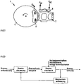
- Fig.1 a disc brake system 1 of a rail vehicle according to a preferred embodiment of the invention, as it is basically, for example, from the DE 102 45 207 C1 is known and is therefore only briefly described below.
- the disc brake system 1 contains, as a brake actuator or brake application device, a brake caliper unit 2 with a service brake unit and a memory brake unit not considered here.
- the brake caliper unit 2 comprises a brake disc 4, which cooperates with, for example, two brake pads 6 in a known manner, of which in the side view of FIG Fig.1 only one can be seen.
- the brake caliper unit 2 is preferably actuated pneumatically in order to generate a braking force F B acting in the circumferential direction of the brake disc 4 in response to a braking request.
- the brake caliper unit 2 could of course also be operated in a different manner by pressure medium, for example hydraulically or also electrically.
- the rail vehicle preferably comprises a plurality of bogies, each with a plurality of such brake actuators or brake caliper units 2, so that the braking forces generated by at least some of these brake caliper units 2 can be measured and evaluated in a control device (not shown here).
- a control device not shown here.
- identical brake caliper units 2 of the rail vehicle is shown in Fig.1 only one shown.
- the sensor device assigned to a brake caliper unit 2 is used to measure the time curve of at least one variable representing the fluctuations in the friction conditions between wheel and rail and / or between brake disc 4 and brake pad 6, such as wheel rotation speed, wheel circumference acceleration, braking force, braking torque or braking pressure, and by one of to control the measured time-dependent signal to a control device, which is designed in such a way that it generates the braking force generated by the brake caliper unit 2 assigned to the wheel or the wheel set and / or the brake disc and the brake pads, depending on the deviation of the time-dependent course of the measured variable from adapts a predefined or expected temporal course of the size.
- a control device which is designed in such a way that it generates the braking force generated by the brake caliper unit 2 assigned to the wheel or the wheel set and / or the brake disc and the brake pads, depending on the deviation of the time-dependent course of the measured variable from adapts a predefined or expected temporal course of the size.
- Such a variable is, for example, the wheel rotation speed, the wheel circumference acceleration, the braking force, the braking torque M A or the braking pressure in the case of a pneumatically actuated brake caliper unit.
- the size could also be the actuating current, for example.
- the braking force in the circumferential direction of the brake disc 4 or the braking torque M A of a brake caliper unit 2 during a braking request is the fluctuations in the friction conditions between the wheel assigned to the brake caliper unit 2 or that of the wheel set assigned to the brake caliper unit 2 and the rail and / or between the brake caliper unit 2 associated brake disc 4 and the brake pads 6 associated brake pads 6 representative size, measured as a time signal or time course over a certain predetermined period and then evaluated with the help of the control device (brake control).
- the braking force or the braking torque or the time profile of the relevant quantity is measured and then the braking force or the braking torque generated by the assigned brake caliper unit 2 depending on the deviation of the time profile of the measured Braking force adapted from a predetermined or expected time course of the braking force.
- the braking torque can naturally also be monitored.
- the time profiles of the braking force or the braking torque M A are measured on a brake caliper unit 2, the control device (brake control) the braking torque M A generated by the brake caliper unit 2 in question depending on the deviation of the measured Circumstances of the braking torque M A influenced by fluctuations in the friction conditions between the assigned wheel or wheel set and the rail and / or between the assigned brake disc 4 and the brake pads 6 from a predetermined or expected time profile of the braking torque (braking request) on this brake caliper unit 2, for example by means of a Adapts brake pressure specification for the preferably pneumatically operated brake caliper unit 2. Fluctuating frictional properties between the assigned wheels and the rail and / or between the brake disc 4 and the brake pads 6 then act as disturbance variables on the brake mechanism of the brake caliper unit 2.
- the brake system of a rail vehicle preferably comprises a plurality of brake actuators or brake caliper units 2, the control device then preferably being designed such that, in the case of one of the brake caliper units 2, the deviation of the measured time profile (preferably the measured time profile of the braking torque) from a predetermined one or an expected course of time is greater than a permitted deviation (that is to say, fluctuations in the friction properties which cannot be tolerated in this one brake caliper unit 2), the braking force or the braking torque is increased in this one brake caliper unit 2 and, for compensation, by a further brake caliper unit 2, in which the deviation of the measured time course from the predetermined or expected time course is smaller than the permitted deviation (ie tolerable fluctuations in the friction properties occur on this further brake caliper unit), generated braking force or generated braking torque is reduced such that the sum of the actual braking forces or actual braking torques obtained in this way of all or at least some brake caliper units 2 corresponds to a target total braking force corresponding to the braking
- an increase in the braking force or the braking torque on the one brake caliper unit 2 compared to the braking request due to disturbing or intolerable fluctuations in the friction conditions between the assigned wheel or wheel set and the rail and / or between the assigned brake disc 4 and the assigned brake pads 6 does not result in overbraking of the rail vehicle, because then at least one further brake caliper unit 2, in which no or tolerable fluctuations in the friction conditions between the assigned wheel or wheel set and the rail and / or between the assigned brake disc 4 and the assigned brake pad 6, results compared to the braking requirement such a lower braking force or such a lower Braking torque is generated that the total braking force or the total braking torque corresponds to the target total braking force or the target total braking torque.
Description
Die Erfindung geht aus von einem Schienenfahrzeug beinhaltend eine Bremsanlage gemäß dem Oberbegriff von Anspruch 1 sowie von einem Verfahren zur Steuerung einer Bremsanlage eines Schienenfahrzeugs gemäß dem Oberbegriff von Anspruch 3.The invention is based on a rail vehicle comprising a brake system according to the preamble of
Eine Bremsanlage eines Schienenfahrzeugs ist beispielsweise aus der
In der gattungsgemäßen
Der vorliegenden Erfindung liegt demgegenüber die Aufgabe zugrunde, ein Schienenfahrzeug mit einer Bremsanlage bzw. ein Verfahren zur Steuerung einer Bremsanlage eines Schienenfahrzeugs der eingangs erwähnten Art derart weiter zu entwickeln, dass die Bremsanlage mit einem relativ geringen Energieaufwand betrieben werden kann.The present invention is based on the object of further developing a rail vehicle with a brake system or a method for controlling a brake system of a rail vehicle of the type mentioned in such a way that the brake system can be operated with a relatively low expenditure of energy.
Diese Aufgabe wird erfindungsgemäß durch die Merkmale von Anspruch 1 und Anspruch 3 gelöst.This object is achieved by the features of
Es wird wenigstens eine Sensoreinrichtung vorgesehen, um den zeitlichen Verlauf wenigstens einer Schwankungen der Reibbedingungen zwischen dem einem Bremsaktuator zugeordneten Rad oder Radsatz und der Schiene und/oder zwischen der einem Bremsaktuator zugeordneten Bremsscheibe und dem bzw. den Bremsbelägen repräsentierenden Größe wie Raddrehgeschwindigkeit, Radumfangsbeschleunigung, Bremskraft, Bremsmoment oder Bremsdruck zu messen und um ein von der gemessenen Größe abhängiges Signal an eine Steuereinrichtung auszusteuern, welche derart ausgebildet ist, dass sie die von dem Bremsaktuator erzeugte Bremskraft abhängig von der Abweichung des zeitlichen Verlaufs der gemessenen Größe von einem vorgegebenen oder erwarteten zeitlichen Verlauf der Größe anpasst.At least one sensor device is provided to determine the time course of at least one fluctuation in the friction conditions between the wheel or wheel set assigned to a brake actuator and the rail and / or between the quantity representing wheel brake speed and wheel circumference acceleration, braking force and the brake disc assigned to a brake actuator and the brake pads To measure braking torque or braking pressure and to control a signal dependent on the measured variable to a control device which is designed such that it applies the braking force generated by the brake actuator as a function of the deviation of the time curve of the measured variable from a predetermined or expected temporal curve adapts to the size.
Mit anderen Worten soll ein gewisser Grad von Schwankungen der Reibbedingungen zwischen Rad oder Radsatz und Schiene und/oder zwischen Bremsscheibe und Bremsbelag toleriert, aber ab einem Grenzwert (erlaubte Abweichung) durch Anpassung der Bremskraft bzw. des Bremsmoments kompensiert werden.In other words, a certain degree of fluctuations in the frictional conditions between the wheel or wheel set and the rail and / or between the brake disc and the brake pad should be tolerated, but from a limit value (permitted deviation) should be compensated for by adapting the braking force or the braking torque.
Bei einem Schienenfahrzeug wirken sich an den gebremsten Achsen Schwankungen der Reibbedingungen zwischen Rad oder Radsatz und Schiene und/oder zwischen Bremsbelägen und Bremsscheibe rückkoppelnd auf den Zeitverlauf der von dem betreffenden oder zugeordneten Bremsaktuator erzeugten Bremskraft aus.In the case of a rail vehicle, fluctuations in the frictional conditions between the wheel or wheel set and the rail and / or between the brake linings and the brake disc have a feedback effect on the time profile of the braking force generated by the relevant or assigned brake actuator.
Vorzugsweise wird daher die Bremskraft in Umfangsrichtung der Bremsscheibe bzw. das Bremsmoment als die Schwankungen der Reibbedingungen zwischen Rad oder Radsatz und Schiene und/oder zwischen Bremsscheibe und den Bremsbelägen repräsentierende Größe herangezogen, als Zeitsignal gemessen und dann mit Hilfe der Steuereinrichtung ausgewertet. Bei konstanter Bremsanforderung deuten dann Abweichungen oder Schwankungen der Bremskraft bzw. des Bremsmoments an einem Bremsaktuator von einem erwarteten Zeitverlauf dieser Größen auf Schwankungen der Reibbedingungen zwischen dem zugeordneten Rad oder Radsatz und der Schiene und/oder zwischen der zugeordneten Bremsscheibe und den Bremsbelägen hin.The braking force in the circumferential direction of the brake disc or the braking torque is therefore preferably used as the variable representing the fluctuations in the friction conditions between the wheel or wheel set and rail and / or between the brake disc and the brake pads, measured as a time signal and then evaluated with the aid of the control device. If the braking requirement is constant, deviations or fluctuations in the braking force or braking torque on a brake actuator from an expected time course of these variables then indicate fluctuations in the friction conditions between the assigned wheel or wheel set and the rail and / or between the assigned brake disc and the brake pads.
Die Sensoreinrichtung ist daher bevorzugt ausgebildet, um die Bremskraft bzw. das Bremsmoment an einem Bremsaktuator zu messen und die Steuereinrichtung, um die vom Bremsaktuator erzeugte Bremskraft abhängig von der Abweichung des zeitlichen Verlaufs der gemessenen Bremskraft von einem vorgegebenen zeitlichen Verlauf der Bremskraft anzupassen. Anstatt der Bremskraft kann natürlich auch das Bremsmoment überwacht werden.The sensor device is therefore preferably designed to measure the braking force or the braking torque on a brake actuator and the control device to adapt the braking force generated by the brake actuator depending on the deviation of the time profile of the measured braking force from a predetermined time profile of the braking force. Instead of the braking force, the braking torque can of course also be monitored.
Als Schwankungen der Reibbedingungen zwischen dem einem Bremsaktuator zugeordneten Rad oder Radsatz und der Schiene bzw. zwischen der einem Bremsaktuator zugeordneten Bremsscheibe und den Bremsbelägen repräsentierende Größe, deren zeitlicher Verlauf zu messen und zu vergleichen ist, ist jedoch auch jede andere Größe denkbar, auf welche sich die Schwankungen der Reibbedingungen auswirken bzw. durch welche diese mess- oder erkennbar ist. Bei Schienenfahrzeugen bzw. bei aus einzelnen Schienenfahrzeugen zusammen gesetzten Zügen kommen beispielsweise auch die Kräfte zwischen den einzelnen Schienenfahrzeugen (Zuglängskräfte) in Frage.Any fluctuations in the friction conditions between the wheel or wheel set assigned to a brake actuator and the rail or between the size of the brake disk assigned to a brake actuator and the brake pads, the course of which can be measured and compared, are also conceivable for any other size to which affect the fluctuations in the friction conditions or by which this can be measured or recognized. In the case of rail vehicles or in the case of trains composed of individual rail vehicles, the forces between the individual rail vehicles (longitudinal train forces) can also be considered, for example.
Die Verwendung der Bremskraft in Umfangsrichtung der Bremsscheibe bzw. des Bremsmoments an einem Bremsaktuator während einer Bremsanforderung als Schwankungen der Reibbedingungen zwischen dem zugeordneten Rad oder Radsatz und der Schiene und/oder zwischen der zugeordneten Bremsscheibe und den Bremsbelägen repräsentierende Größe hat den Vorteil, dass Bremsanlagen von Schienenfahrzeugen meist ohnehin mit einer Bremskraftregelung und damit mit einer entsprechenden Sensorik ausgerüstet sind, wie in der
Durch die Anpassung der Bremskraft während einer Bremsanforderung abhängig von den gemessenen Schwankungen der Reibbedingungen wird dann der Anpressdruck der Bremsbeläge an die Bremsscheibe bzw. die an am Radumfang wirksame Bremskraft verändert. Besonders bevorzugt wird dabei die Bremskraft gegenüber einer der jeweiligen Bremsanforderung entsprechenden Soll-Bremskraft etwas erhöht, um ungünstige Reibbedingungen wie beispielsweise einen zu niedrigen, durch Umweltbedingungen verursachten Reibbeiwert zwischen Rad und Schiene und/oder zwischen Bremsscheibe und Bremsbelag durch eine erhöhte Bremskraft an dem betreffenden Bremsaktuator zu kompensieren.By adjusting the braking force during a braking request depending on the measured fluctuations in the friction conditions, the contact pressure of the brake pads against the brake disc or the braking force effective at the wheel circumference is then changed. Particularly preferably, the braking force is increased somewhat compared to a target braking force corresponding to the respective braking requirement, in order to avoid unfavorable friction conditions such as, for example, a friction coefficient between the wheel and the rail and / or between the brake disc and the brake lining caused by environmental conditions, due to an increased braking force on the brake actuator in question to compensate.
Erfindungsgemäß umfasst die Bremsanlage mehrere Bremsaktuatoren, wobei die Steuereinrichtung derart ausgebildet ist, dass sie, falls bei einem Bremsaktuator die Abweichung des zeitlichen Verlaufs der gemessenen Größe von einem vorgegebenen oder erwarteten zeitlichen Verlauf der Größe größer als eine erlaubte Abweichung ist, die Bremskraft bei dem einen Bremsaktuator vergrößert und zur Kompensation die durch einen weiteren Bremsaktuator, bei welchem die Abweichung des zeitlichen Verlaufs der gemessenen Größe von einem vorgegebenen oder erwarteten zeitlichen Verlauf der Größe kleiner als die erlaubte Abweichung ist, erzeugte Bremskraft derart reduziert wird, dass die Summe der auf diese Weise erhaltenen Ist-Bremskräfte der Bremsaktuatoren einer der Bremsanforderung entsprechenden Soll-Gesamtbremskraft entspricht.According to the invention, the brake system comprises a plurality of brake actuators, the control device being designed in such a way that, in the case of a brake actuator, if the deviation of the time profile of the measured variable from a predetermined or expected temporal profile of the variable is greater than an allowable deviation, the braking force in one Brake actuator increases and, for compensation, the braking force generated by a further brake actuator, in which the deviation of the time course of the measured variable from a predetermined or expected temporal curve of the variable is smaller than the permitted deviation, is reduced in such a way that the sum of the braking forces in this way received actual braking forces of the brake actuators corresponds to a target total braking force corresponding to the braking request.
In diesem Fall führt also eine Erhöhung der Bremskraft bzw. des Bremsmoments gegenüber der Bremsanforderung an einem Bremsaktuator mit ungünstigen oder nicht mehr tolerierbaren Schwankungen der Reibbedingungen zwischen zugeordnetem Rad oder Radsatz und Schiene und/oder zwischen der zugeordneten Bremsscheibe und den Bremsbelägen nicht zu einer Überbremsung, weil dann durch wenigstens einen weiteren Bremsaktuator, bei welchem keine oder tolerierbare Schwankungen der Reibbedingungen zwischen dem zugeordneten Rad oder Radsatz und Schiene und/oder zwischen der zugeordneten Bremsscheibe und den Bremsbelägen vorliegen, eine gegenüber der Bremsanforderung derart geringere Bremskraft bzw. ein derart geringeres Bremsmoment erzeugt wird, dass die Gesamt-Bremskraft bzw. das Gesamt-Bremsmoment der Soll-Gesamtbremskraft bzw. dem Soll-Gesamtbremsmoment entspricht. Die Summe der derart erzeugten Bremsmomente an verschiedenen Bremsaktuatoren bleibt daher unverändert.In this case, an increase in the braking force or the braking torque compared to the braking request on a brake actuator with unfavorable or no longer tolerable fluctuations in the friction conditions between the assigned wheel or wheelset and rail and / or between the assigned brake disc and the brake pads does not lead to overbraking, because then at least one further brake actuator, in which there are no or tolerable fluctuations in the friction conditions between the assigned wheel or wheel set and rail and / or between the assigned brake disc and the brake pads, generates a braking force that is lower than the braking requirement or braking torque is that the total braking force or the total braking torque corresponds to the target total braking force or the target total braking torque. The sum of the braking torques generated in this way on various brake actuators therefore remains unchanged.
Genaueres geht aus der folgenden Beschreibung eines Ausführungsbeispiels hervor.More detailed information can be found in the following description of an exemplary embodiment.
Nachstehend ist ein Ausführungsbeispiel der Erfindung in der Zeichnung dargestellt und in der nachfolgenden Beschreibung näher erläutert. In der Zeichnung zeigt
- Fig.1
- eine schematische Seitendarstellung einer Scheibenbremsanlage eines Schienenfahrzeugs gemäß einer bevorzugten Ausführungsform der Erfindung;
- Fig.2
- ein Flussdiagramm einer Bremskraft- oder Bremsmomentenanpassung zur Kompensation von Schwankungen der Reibbedingungen zwischen Rad oder Radsatz und Schiene bzw. zwischen Bremsscheibe und Bremsbelägen gemäß einer bevorzugten Ausführungsform der Erfindung.
- Fig.1
- is a schematic side view of a disc brake system of a rail vehicle according to a preferred embodiment of the invention;
- Fig.2
- a flowchart of a braking force or braking torque adjustment to compensate for fluctuations in the frictional conditions between the wheel or wheelset and rail or between the brake disc and brake pads according to a preferred embodiment of the invention.
In
Die Scheibenbremsanlage 1 beinhaltet als Bremsaktuator oder Bremszuspanneinrichtung eine Bremszangeneinheit 2 mit einer Betriebsbremseinheit und einer hier nicht betrachteten Speicherbremseinheit. Die Bremszangeneinheit 2 umfasst eine Bremsscheibe 4, welche mit beispielsweise zwei Bremsbelägen 6 in bekannter Weise zusammen wirkt, von welchen in der Seitenansicht von
Da die Bremszangeneinheit 2 über einen Halter 8 an einem hier nicht gezeigten Drehgestell des Schienenfahrzeugs abgestützt ist, wirkt an dem Halter 8 ein Reaktionsmoment MA bzw. Reaktionskräfte FA1, FA2 in voneinander beabstandeten Befestigungsstellen des Halters 8 am Drehgestell, welche mittels einer Kraft messenden Sensorik wie beispielsweise Dehnmessstreifen an entsprechenden Verbindungsbauteilen zwischen dem Halter 8 und dem Drehgestell messbar sind. Das Schienenfahrzeug umfasst bevorzugt mehrere Drehgestelle mit jeweils mehreren solcher Bremsaktuatoren bzw. Bremszangeneinheiten 2, so dass die von wenigstens einigen dieser Bremszangeneinheiten 2 erzeugten Bremskräfte gemessen und in einer hier nicht gezeigten Steuereinrichtung ausgewertet werden können. Von den beispielsweise identisch aufgebauten Bremszangeneinheiten 2 des Schienenfahrzeugs ist in
Insbesondere dient die einer Bremszangeneinheit 2 zugeordnete Sensoreinrichtung dazu, um den zeitlichen Verlauf wenigstens einer Schwankungen der Reibbedingungen zwischen Rad und Schiene und/oder zwischen Bremsscheibe 4 und Bremsbelag 6 repräsentierenden Größe wie Raddrehgeschwindigkeit, Radumfangsbeschleunigung, Bremskraft, Bremsmoment oder Bremsdruck zu messen und um ein von dem gemessenen zeitlichen Verlauf abhängiges Signal an eine Steuereinrichtung auszusteuern, welche derart ausgebildet ist, dass sie die von der dem Rad oder dem Radsatz und/oder der Bremsscheibe und den Bremsbelägen zugeordnete Bremszangeneinheit 2 erzeugte Bremskraft abhängig von der Abweichung des zeitlichen Verlaufs der gemessenen Größe von einem vorgegebenen oder erwarteten zeitlichen Verlauf der Größe anpasst.In particular, the sensor device assigned to a
Als eine solche Größe kommt beispielsweise die Raddrehgeschwindigkeit, die Radumfangsbeschleunigung, die Bremskraft, das Bremsmoment MA oder auch der Bremsdruck bei einer pneumatisch betätigten Bremszangeneinheit in Frage. Bei elektrisch betätigten Bremszangeneinheiten 2 könnte die Größe beispielsweise auch der Betätigungsstrom sein.Such a variable is, for example, the wheel rotation speed, the wheel circumference acceleration, the braking force, the braking torque M A or the braking pressure in the case of a pneumatically actuated brake caliper unit. In the case of electrically operated
Vorzugsweise wird die Bremskraft in Umfangsrichtung der Bremsscheibe 4 bzw. das Bremsmoment MA einer Bremszangeneinheit 2 während einer Bremsanforderung als die Schwankungen der Reibbedingungen zwischen dem der Bremszangeneinheit 2 zugeordneten Rad oder dem der der Bremszangeneinheit 2 zugeordneten Radsatz und der Schiene und/oder zwischen der Bremszangeneinheit 2 zugeordneten Bremsscheibe 4 und den Bremszangeneinheit 2 zugeordneten Bremsbelägen 6 repräsentierende Größe herangezogen, als Zeitsignal bzw. zeitlicher Verlauf über eine bestimmten vorgegebenen Zeitraum gemessen und dann mit Hilfe der Steuereinrichtung (Bremsteuerung) ausgewertet.Preferably, the braking force in the circumferential direction of the
Mit anderen Worten wird in diesem Fall die Bremskraft bzw. das Bremsmoment bzw. der zeitliche Verlauf der betreffenden Größe gemessen und dann die von der zugeordneten Bremszangeneinheit 2 erzeugte Bremskraft bzw. das Bremsmoment abhängig von der Abweichung des zeitlichen Verlaufs der gemessenen Bremskraft von einem vorgegebenen oder erwarteten zeitlichen Verlauf der Bremskraft angepasst. Anstatt der Bremskraft kann natürlich auch das Bremsmoment überwacht werden.In other words, in this case the braking force or the braking torque or the time profile of the relevant quantity is measured and then the braking force or the braking torque generated by the assigned
Auch können anstatt nur einer Größe auch mehrere, Schwankungen der Reibbedingungen zwischen Rad oder Radsatz und Schiene und/oder zwischen Bremsscheibe 4 und Bremsbelag 6 repräsentierende und der betreffenden Bremszangeneinheit 2 zugeordnete Größen parallel überwacht werden. Bei konstanter Bremsanforderung deuten dann Änderungen oder Schwankungen im zeitlichen Verlauf der gemessenen Bremskraft bzw. des gemessenen Bremsmoments MA bzw. Abweichungen vom erwarteten Zeitverlauf auf Schwankungen der Reibbedingungen zwischen dem der betreffenden Bremszangeneinheit 2 zugeordneten Rad oder Radsatz und der Schiene und/oder zwischen der Bremsscheibe 4 und den Bremsbelägen 6 an der betreffenden Bremszangeneinheit 2 hin.Instead of just one variable, it is also possible to monitor several variables which represent fluctuations in the friction conditions between the wheel or wheel set and the rail and / or between the
Wie aus
In der Praxis bevorzugt umfasst die Bremsanlage eines Schienenfahrzeugs mehrere Bremsaktuatoren bzw. Bremszangeneinheiten 2, wobei die Steuereinrichtung dann bevorzugt derart ausgebildet ist, dass sie, falls bei einer der Bremszangeneinheiten 2 die Abweichung des gemessenen Zeitverlaufs (vorzugsweise des gemessenen Zeitverlaufs des Bremsmoments) von einem vorgegebenen oder einem erwarteten Zeitverlauf größer als eine erlaubte Abweichung ist (d.h. es treten an dieser einen Bremszangeneinheit 2 nicht tolerierbare Schwankungen der Reibeigenschaften auf), die Bremskraft bzw. das Bremsmoment bei dieser einen Bremszangeneinheit 2 vergrößert und zur Kompensation die bzw. das durch eine weitere Bremszangeneinheit 2, bei welcher die Abweichung des gemessenen Zeitverlaufs von dem vorgegebenen oder erwarteten Zeitverlauf kleiner als die erlaubte Abweichung ist (d.h. es treten an dieser weiteren Bremszangeneinheit 2 tolerierbare Schwankungen der Reibeigenschaften auf), erzeugte Bremskraft bzw. erzeugte Bremsmoment derart reduziert wird, dass die Summe der auf diese Weise erhaltenen Ist-Bremskräfte bzw. Ist-Bremsmomente aller oder wenigstens einiger Bremszangeneinheiten 2 einer der Bremsanforderung entsprechenden Soll-Gesamtbremskraft bzw. einem der Bremsanforderung entsprechenden Soll-Gesamtbremsmoment entspricht.In practice, the brake system of a rail vehicle preferably comprises a plurality of brake actuators or
In diesem Fall führt beispielsweise eine Erhöhung der Bremskraft bzw. des Bremsmoments an der einen Bremszangeneinheit 2 gegenüber der Bremsanforderung aufgrund störender oder nicht tolerierbarer Schwankungen der Reibbedingungen zwischen dem zugeordneten Rad oder Radsatz und der Schiene und/oder zwischen der zugeordneten Bremsscheibe 4 und den zugeordneten Bremsbelägen 6 nicht zu einer Überbremsung des Schienenfahrzeugs, weil dann durch wenigstens eine weitere Bremszangeneinheit 2, bei welcher keine oder tolerierbare Schwankungen der Reibbedingungen zwischen dem zugeordneten Rad oder Radsatz und der Schiene und/oder zwischen der zugeordneten Bremsscheibe 4 und dem zugeordneten Bremsbelag 6 auftreten, eine gegenüber der Bremsanforderung derart geringere Bremskraft bzw. ein derart geringeres Bremsmoment erzeugt wird, dass die Gesamt-Bremskraft bzw. das Gesamt-Bremsmoment der Soll-Gesamtbremskraft bzw. dem Soll-Gesamtbremsmoment entspricht.In this case, for example, an increase in the braking force or the braking torque on the one
- 11
- Bremsanlagebraking system
- 22
- BremszangeneinheitBrake caliper unit
- 44
- Bremsscheibebrake disc
- 66
- BremsbelägeBrake pads
- 88th
- Halterholder
Claims (4)
- Rail vehicle comprising a brake system (1), having at least one brake actuator (2) which is assigned to a wheel or a wheel set and comprises at least one brake disk (4) and at least one brake lining (6) which interacts with the former in order to generate a braking force in response to a braking demand, wherein at least one sensor device is provided for measuring the time profile of at least one variable, such as a wheel rotational speed, wheel circumferential acceleration, braking force, braking torque or brake pressure, which represents fluctuations in the friction conditions between the wheel or wheel set assigned to the brake actuator (2) and the rail and/or between the brake disk (4) assigned to the brake actuator (2) and the at least one brake lining (6), and for modulating a signal which is dependent on the measured variable and is output to a control device, wherein the control device is embodied in such a way that it adapts the braking force generated by the brake actuator (2) as a function of the deviation of the time profile of the measured variable from a predefined or expected time profile of the variable, characterized in that the brake system comprises a plurality of brake actuators (2), and the control device is embodied in such a way that, if the deviation of the time profile of the measured variable from a predefined or expected time profile of the variable is greater than a permitted deviation at one brake actuator (2), the braking force at the one brake actuator (2) is increased and, for the purpose of compensation, the braking force which is generated by a further brake actuator (2) at which the deviation of the time profile of the measured variable from a predefined or expected time profile of the variable is smaller than the permitted deviation is reduced in such a way that the sum of the actual braking forces, obtained in this way, of the brake actuators (2) corresponds to an overall setpoint braking force corresponding to the braking demand.
- Rail vehicle according to Claim 1, characterized in that the variable which represents the fluctuations in the friction conditions between the wheel or the wheel set and the rail and/or between the brake disk (4) and the brake lining (6) is the braking force generated by the assigned brake actuator (2) or the braking torque generated by the assigned brake actuator (2).
- Method for controlling a brake system (1) of a rail vehicle, having at least one brake actuator (2) which is assigned to a wheel or a wheel set and comprises at least one brake disk (4) and at least one brake lining (6) which interacts with the former in order to generate a braking force in response to a braking demand, comprising the following steps:a) measurement of the time profile of at least one variable, such as wheel rotational speed, wheel circumferential acceleration, braking force, braking torque or brake pressure, which represents fluctuations in the friction conditions between the wheel or wheel set assigned to the brake actuator (2) and the rail and/or between the assigned brake disk (4) and the at least one brake lining (6),b) adaptation of the braking force generated by the brake actuator (2) as a function of the deviation of the time profile of the measured variable from a predefined or expected time profile of the variable, characterized in thatc) if the deviation of the time profile of the measured variable from a predefined or expected time profile of the variable is greater than a permitted deviation at one brake actuator (2), the braking force at the one brake actuator (2) is increased and, for the purpose of compensation, the braking force which is generated by a further brake actuator (2) at which the deviation of the time profile of the measured variable from a predefined or expected time profile of the variable is smaller than the permitted deviation is reduced in such a way that the sum of the actual braking forces, obtained in this way, of the brake actuators (2) corresponds to an overall setpoint braking force corresponding to the braking demand.
- Method according to Claim 3, characterized in that the variable which represents the fluctuations in the friction conditions between the wheel or wheel set and the rail and/or between the brake disk (4) and the brake lining (6) is the braking force generated by the brake actuator (2) or the braking torque.
Applications Claiming Priority (2)
| Application Number | Priority Date | Filing Date | Title |
|---|---|---|---|
| DE102008063892A DE102008063892B4 (en) | 2008-12-19 | 2008-12-19 | Brake system of a rail vehicle with compensation of fluctuations in the friction conditions |
| PCT/EP2009/008873 WO2010069520A2 (en) | 2008-12-19 | 2009-12-11 | Brake system of a rail vehicle with compensation of fluctuations of the friction conditions |
Publications (2)
| Publication Number | Publication Date |
|---|---|
| EP2379381A2 EP2379381A2 (en) | 2011-10-26 |
| EP2379381B1 true EP2379381B1 (en) | 2020-02-26 |
Family
ID=42234636
Family Applications (1)
| Application Number | Title | Priority Date | Filing Date |
|---|---|---|---|
| EP09774639.0A Active EP2379381B1 (en) | 2008-12-19 | 2009-12-11 | Brake system of a rail vehicle with compensation of fluctuations of the friction conditions |
Country Status (12)
| Country | Link |
|---|---|
| US (1) | US9156449B2 (en) |
| EP (1) | EP2379381B1 (en) |
| JP (1) | JP6012179B2 (en) |
| KR (1) | KR101606956B1 (en) |
| CN (1) | CN102256847B (en) |
| AU (1) | AU2009328602B2 (en) |
| BR (1) | BRPI0923066B1 (en) |
| CA (1) | CA2748222C (en) |
| DE (1) | DE102008063892B4 (en) |
| HK (1) | HK1164234A1 (en) |
| RU (1) | RU2526869C2 (en) |
| WO (1) | WO2010069520A2 (en) |
Families Citing this family (27)
| Publication number | Priority date | Publication date | Assignee | Title |
|---|---|---|---|---|
| DE102010049303A1 (en) | 2010-10-22 | 2012-04-26 | Knorr-Bremse Systeme für Schienenfahrzeuge GmbH | Method for controlling a sliding friction-controlled friction brake system of a rail vehicle |
| DE102010053683A1 (en) * | 2010-12-08 | 2012-06-14 | Knorr-Bremse Systeme für Schienenfahrzeuge GmbH | Method for controlling a sliding friction-controlled friction brake system of a rail vehicle |
| DE102011113117A1 (en) * | 2011-09-09 | 2013-03-14 | Knorr-Bremse Systeme für Schienenfahrzeuge GmbH | Brake control device for rail vehicles, brake system for rail vehicles and methods for brake control for rail vehicles and computer program product |
| DE102011113073C5 (en) | 2011-09-09 | 2022-03-10 | Knorr-Bremse Systeme für Schienenfahrzeuge GmbH | Improved Braking for a Rail Vehicle |
| DE102011113025A1 (en) | 2011-09-09 | 2013-03-14 | Knorr-Bremse Systeme für Schienenfahrzeuge GmbH | Brake control device for a brake system of a rail vehicle, brake system, rail vehicle and method for operating a brake control device |
| DE102011113093A1 (en) * | 2011-09-09 | 2013-03-14 | Knorr-Bremse Systeme für Schienenfahrzeuge GmbH | Brake effect determination for a rail vehicle |
| DE102012005068B4 (en) * | 2012-03-15 | 2020-09-03 | Knorr-Bremse Systeme für Schienenfahrzeuge GmbH | Method for controlling a drive and braking device of a vehicle having a friction brake |
| CN103112472B (en) * | 2013-01-29 | 2015-06-10 | 常州庞丰机电科技有限公司 | Hydraulic pressure braking clamp device |
| DE102013008227A1 (en) | 2013-05-13 | 2014-11-13 | Knorr-Bremse Systeme für Schienenfahrzeuge GmbH | Method and device for determining a braking torque on a brake system for a rail vehicle |
| DE102013213618A1 (en) | 2013-07-11 | 2015-01-15 | Siemens Aktiengesellschaft | braking device |
| DE102013213619A1 (en) | 2013-07-11 | 2015-01-15 | Siemens Aktiengesellschaft | Brake application device for a disc brake device |
| EP2918459B1 (en) * | 2014-03-14 | 2021-01-20 | Bombardier Transportation GmbH | Method for determining an adhesion coefficient between a wheel of a railway vehicle and a rail |
| DE102014214652A1 (en) * | 2014-07-25 | 2016-01-28 | Siemens Aktiengesellschaft | Method and arrangement for monitoring the driving state of a vehicle and vehicle with such an arrangement |
| US10119873B2 (en) | 2014-09-15 | 2018-11-06 | Westinghouse Air Brake Technologies Corporation | Brake force sensor arrangement for a brake unit |
| DE102014116803A1 (en) | 2014-11-17 | 2016-05-19 | Knorr-Bremse Systeme für Schienenfahrzeuge GmbH | Brake device and method for uniform braking |
| DE102014119492A1 (en) * | 2014-12-23 | 2016-06-23 | Knorr-Bremse Systeme für Schienenfahrzeuge GmbH | Brake pad holder, brake pad and pad holder |
| DE102015205099B4 (en) * | 2015-03-20 | 2021-05-06 | Bombardier Transportation Gmbh | Braking a rail vehicle |
| EP3168111A1 (en) * | 2015-11-11 | 2017-05-17 | KNORR-BREMSE Systeme für Schienenfahrzeuge GmbH | Control system with adhesion map for rail vehicles |
| DE102015226344A1 (en) | 2015-12-21 | 2017-06-22 | Knorr-Bremse Systeme für Schienenfahrzeuge GmbH | Brake control for rail vehicles with adaptive lining characteristic |
| DE102016101838A1 (en) * | 2016-02-03 | 2017-08-03 | Knorr-Bremse Systeme für Schienenfahrzeuge GmbH | Device and method for force measurement for a brake force test stand |
| DE102016107319A1 (en) | 2016-04-20 | 2017-10-26 | Knorr-Bremse Systeme für Schienenfahrzeuge GmbH | Brake device for a rail vehicle and method for determining a braking torque of such a brake device |
| DE102016107317A1 (en) | 2016-04-20 | 2017-10-26 | Knorr-Bremse Systeme für Schienenfahrzeuge GmbH | Braking device for a rail vehicle and method for determining a braking torque of a braking device |
| CN106122369B (en) * | 2016-06-23 | 2018-05-08 | 上海中船三井造船柴油机有限公司 | A kind of electric device for the compensation of diesel engine second moment |
| DE102017011148A1 (en) * | 2017-12-01 | 2019-06-06 | Knorr-Bremse Systeme für Schienenfahrzeuge GmbH | Method for determining a required contact pressure of a brake |
| DE102018112846A1 (en) * | 2018-05-29 | 2019-12-05 | Knorr-Bremse Systeme für Schienenfahrzeuge GmbH | Control device and method for controlling an actuator for actuating brake means of a vehicle, in particular a rail vehicle |
| CN111336194A (en) * | 2020-03-09 | 2020-06-26 | 安徽理工大学 | Controllable electromagnetic normally closed disc brake |
| JP2022117698A (en) * | 2021-02-01 | 2022-08-12 | ナブテスコ株式会社 | Brake device for vehicle |
Family Cites Families (17)
| Publication number | Priority date | Publication date | Assignee | Title |
|---|---|---|---|---|
| DE3500745A1 (en) * | 1985-01-11 | 1986-07-17 | Alfred Teves Gmbh, 6000 Frankfurt | METHOD AND CIRCUIT ARRANGEMENT FOR ADJUSTING THE SLIP CONTROL TO THE CURRENT FRICTION VALUE |
| DE4137546C2 (en) * | 1991-11-12 | 1994-01-20 | Mannesmann Ag | Method and device for determining the actual speed of travel in rail vehicles |
| DE4418769C1 (en) * | 1994-05-28 | 1995-08-24 | Daimler Benz Ag | Damping of hunting in vehicle electronic traction control system |
| US5613744A (en) * | 1995-05-24 | 1997-03-25 | Allied Signal, Inc. | Incipient brake fade detection for traction control systems |
| JP3636572B2 (en) | 1997-06-16 | 2005-04-06 | 財団法人鉄道総合技術研究所 | Brake force control device and brake force control method |
| JP3942747B2 (en) * | 1998-09-25 | 2007-07-11 | カヤバ工業株式会社 | Brake torque detector |
| DE10027667B4 (en) * | 2000-06-03 | 2010-04-08 | Robert Bosch Gmbh | Method and device for determining an underlying value of at least one measured variable of a brake system |
| JP4446561B2 (en) * | 2000-06-14 | 2010-04-07 | 本田技研工業株式会社 | Vehicle travel safety device |
| DE10248852B4 (en) | 2001-11-06 | 2012-05-31 | Continental Teves Ag & Co. Ohg | Method for eliminating brake torque fluctuations in a motor vehicle brake system |
| JP2003291797A (en) | 2002-03-29 | 2003-10-15 | Railway Technical Res Inst | Brake control device of railway vehicle |
| DE10245207C1 (en) * | 2002-09-27 | 2003-10-23 | Knorr Bremse Systeme | Brake operating device for rail vehicle brake, has shear force measuring bolt used for incorporated brake force measurement |
| DE10322451A1 (en) * | 2003-05-19 | 2004-12-09 | Continental Teves Ag & Co. Ohg | Process for optimizing the friction coefficient of brake linings of a friction brake |
| JP2005329740A (en) * | 2004-05-18 | 2005-12-02 | Toyota Motor Corp | Vehicular braking system |
| RU2283786C1 (en) * | 2005-03-01 | 2006-09-20 | Общество с ограниченной ответственностью "Научно-производственное объединение САУТ" | Train braking automatic control device |
| DE102005062416A1 (en) * | 2005-12-27 | 2007-07-05 | Knorr-Bremse Systeme für Nutzfahrzeuge GmbH | Disk brake friction value determination involves computing the friction value using the motor current for application and release, idle current, wedge angle, transfer constant and clamping force |
| DE102006058882B4 (en) | 2006-12-13 | 2021-01-14 | Continental Automotive Gmbh | Separate recording of application and friction forces on a brake |
| US7765859B2 (en) * | 2008-04-14 | 2010-08-03 | Wabtec Holding Corp. | Method and system for determining brake shoe effectiveness |
-
2008
- 2008-12-19 DE DE102008063892A patent/DE102008063892B4/en active Active
-
2009
- 2009-12-11 CA CA2748222A patent/CA2748222C/en active Active
- 2009-12-11 RU RU2011129814/11A patent/RU2526869C2/en active
- 2009-12-11 EP EP09774639.0A patent/EP2379381B1/en active Active
- 2009-12-11 US US13/139,861 patent/US9156449B2/en active Active
- 2009-12-11 AU AU2009328602A patent/AU2009328602B2/en active Active
- 2009-12-11 BR BRPI0923066-1A patent/BRPI0923066B1/en active IP Right Grant
- 2009-12-11 KR KR1020117016760A patent/KR101606956B1/en active IP Right Grant
- 2009-12-11 CN CN200980151066.8A patent/CN102256847B/en active Active
- 2009-12-11 WO PCT/EP2009/008873 patent/WO2010069520A2/en active Application Filing
- 2009-12-11 JP JP2011541174A patent/JP6012179B2/en active Active
-
2012
- 2012-05-17 HK HK12104873.0A patent/HK1164234A1/en unknown
Non-Patent Citations (1)
| Title |
|---|
| None * |
Also Published As
| Publication number | Publication date |
|---|---|
| RU2011129814A (en) | 2013-01-27 |
| JP2012512091A (en) | 2012-05-31 |
| WO2010069520A2 (en) | 2010-06-24 |
| KR20110095425A (en) | 2011-08-24 |
| CA2748222A1 (en) | 2010-06-24 |
| RU2526869C2 (en) | 2014-08-27 |
| BRPI0923066A2 (en) | 2016-01-26 |
| BRPI0923066B1 (en) | 2019-10-01 |
| US20120018260A1 (en) | 2012-01-26 |
| CN102256847A (en) | 2011-11-23 |
| AU2009328602A1 (en) | 2011-07-07 |
| US9156449B2 (en) | 2015-10-13 |
| DE102008063892B4 (en) | 2010-11-04 |
| CN102256847B (en) | 2014-05-21 |
| EP2379381A2 (en) | 2011-10-26 |
| KR101606956B1 (en) | 2016-03-28 |
| CA2748222C (en) | 2018-04-24 |
| WO2010069520A3 (en) | 2011-01-06 |
| DE102008063892A1 (en) | 2010-07-08 |
| HK1164234A1 (en) | 2012-09-21 |
| JP6012179B2 (en) | 2016-10-25 |
| AU2009328602B2 (en) | 2014-10-02 |
Similar Documents
| Publication | Publication Date | Title |
|---|---|---|
| EP2379381B1 (en) | Brake system of a rail vehicle with compensation of fluctuations of the friction conditions | |
| EP2648949B1 (en) | Method for controlling an antiskid-regulated friction brake system of a rail vehicle | |
| EP2379382B1 (en) | Brake system of a rail vehicle with reduced stick-slip effect | |
| DE112009000583B4 (en) | Rail vehicle brake device, rail vehicle and method | |
| EP2630013B1 (en) | Method for controlling an antislip-regulated friction brake system of a rail vehicle | |
| EP0189082B1 (en) | Device for measuring and/or regulating a braking force and/or braking torque | |
| DE102011006002A1 (en) | Actuator for a braking system of a rail vehicle | |
| EP3665048B1 (en) | Method and apparatus for determining changes in the longitudinal dynamic behaviour of a rail vehicle | |
| WO2016166278A1 (en) | Method for increasing the operational safety of functional parts of a vehicle brake exposed to thermal stress | |
| DE10026125A1 (en) | Device and method for detecting and / or compensating for irregularities in a wheel brake | |
| WO2013034693A2 (en) | Determining a braking force for a rail vehicle | |
| EP1359078B1 (en) | Method and apparatus for controlling the brake application energy of electronic controlled braking systems of vehicles | |
| EP3027930B1 (en) | Method for monitoring a brake and brake which is monitored by the method | |
| EP2211071B1 (en) | Method for controlling a pressurised air-actuated disc brake with self-reinforcement and a corresponding disc brake | |
| DE102011113120B4 (en) | Brake control device for a brake system of a rail vehicle, brake system, rail vehicle and method for controlling a brake system | |
| WO2010115537A2 (en) | Method and device for controlling braking power | |
| EP4259496A1 (en) | Method for estimating a coefficient of friction, brake control method and brake control device for a rail vehicle | |
| WO2020182566A1 (en) | Method and drive assembly for operating a rail vehicle | |
| EP3611397B1 (en) | Method for force sensing | |
| DE102006015032A1 (en) | Frictional coefficient determination method, especially for motor vehicle brakes, involves determining frictional relationship between frictional coefficients and normal force components | |
| DE102019123454B4 (en) | Method for forecasting the wear of a component of a vehicle and vehicle | |
| WO2024033164A1 (en) | Control apparatus for a braking device of a rail vehicle | |
| DE2923454A1 (en) | Braking control mechanism for rail vehicle - automatically adjusts braking force to prevailing conditions using force measurer attached to chassis |
Legal Events
| Date | Code | Title | Description |
|---|---|---|---|
| PUAI | Public reference made under article 153(3) epc to a published international application that has entered the european phase |
Free format text: ORIGINAL CODE: 0009012 |
|
| 17P | Request for examination filed |
Effective date: 20110719 |
|
| AK | Designated contracting states |
Kind code of ref document: A2 Designated state(s): AT BE BG CH CY CZ DE DK EE ES FI FR GB GR HR HU IE IS IT LI LT LU LV MC MK MT NL NO PL PT RO SE SI SK SM TR |
|
| DAX | Request for extension of the european patent (deleted) | ||
| STAA | Information on the status of an ep patent application or granted ep patent |
Free format text: STATUS: EXAMINATION IS IN PROGRESS |
|
| 17Q | First examination report despatched |
Effective date: 20190409 |
|
| GRAP | Despatch of communication of intention to grant a patent |
Free format text: ORIGINAL CODE: EPIDOSNIGR1 |
|
| STAA | Information on the status of an ep patent application or granted ep patent |
Free format text: STATUS: GRANT OF PATENT IS INTENDED |
|
| INTG | Intention to grant announced |
Effective date: 20191029 |
|
| GRAS | Grant fee paid |
Free format text: ORIGINAL CODE: EPIDOSNIGR3 |
|
| GRAA | (expected) grant |
Free format text: ORIGINAL CODE: 0009210 |
|
| STAA | Information on the status of an ep patent application or granted ep patent |
Free format text: STATUS: THE PATENT HAS BEEN GRANTED |
|
| AK | Designated contracting states |
Kind code of ref document: B1 Designated state(s): AT BE BG CH CY CZ DE DK EE ES FI FR GB GR HR HU IE IS IT LI LT LU LV MC MK MT NL NO PL PT RO SE SI SK SM TR |
|
| REG | Reference to a national code |
Ref country code: GB Ref legal event code: FG4D Free format text: NOT ENGLISH |
|
| REG | Reference to a national code |
Ref country code: CH Ref legal event code: EP |
|
| REG | Reference to a national code |
Ref country code: AT Ref legal event code: REF Ref document number: 1237252 Country of ref document: AT Kind code of ref document: T Effective date: 20200315 |
|
| REG | Reference to a national code |
Ref country code: IE Ref legal event code: FG4D Free format text: LANGUAGE OF EP DOCUMENT: GERMAN |
|
| REG | Reference to a national code |
Ref country code: DE Ref legal event code: R096 Ref document number: 502009016120 Country of ref document: DE |
|
| PG25 | Lapsed in a contracting state [announced via postgrant information from national office to epo] |
Ref country code: FI Free format text: LAPSE BECAUSE OF FAILURE TO SUBMIT A TRANSLATION OF THE DESCRIPTION OR TO PAY THE FEE WITHIN THE PRESCRIBED TIME-LIMIT Effective date: 20200226 Ref country code: NO Free format text: LAPSE BECAUSE OF FAILURE TO SUBMIT A TRANSLATION OF THE DESCRIPTION OR TO PAY THE FEE WITHIN THE PRESCRIBED TIME-LIMIT Effective date: 20200526 |
|
| REG | Reference to a national code |
Ref country code: NL Ref legal event code: MP Effective date: 20200226 |
|
| REG | Reference to a national code |
Ref country code: LT Ref legal event code: MG4D |
|
| PG25 | Lapsed in a contracting state [announced via postgrant information from national office to epo] |
Ref country code: HR Free format text: LAPSE BECAUSE OF FAILURE TO SUBMIT A TRANSLATION OF THE DESCRIPTION OR TO PAY THE FEE WITHIN THE PRESCRIBED TIME-LIMIT Effective date: 20200226 Ref country code: LV Free format text: LAPSE BECAUSE OF FAILURE TO SUBMIT A TRANSLATION OF THE DESCRIPTION OR TO PAY THE FEE WITHIN THE PRESCRIBED TIME-LIMIT Effective date: 20200226 Ref country code: SE Free format text: LAPSE BECAUSE OF FAILURE TO SUBMIT A TRANSLATION OF THE DESCRIPTION OR TO PAY THE FEE WITHIN THE PRESCRIBED TIME-LIMIT Effective date: 20200226 Ref country code: GR Free format text: LAPSE BECAUSE OF FAILURE TO SUBMIT A TRANSLATION OF THE DESCRIPTION OR TO PAY THE FEE WITHIN THE PRESCRIBED TIME-LIMIT Effective date: 20200527 Ref country code: BG Free format text: LAPSE BECAUSE OF FAILURE TO SUBMIT A TRANSLATION OF THE DESCRIPTION OR TO PAY THE FEE WITHIN THE PRESCRIBED TIME-LIMIT Effective date: 20200526 Ref country code: IS Free format text: LAPSE BECAUSE OF FAILURE TO SUBMIT A TRANSLATION OF THE DESCRIPTION OR TO PAY THE FEE WITHIN THE PRESCRIBED TIME-LIMIT Effective date: 20200626 |
|
| PG25 | Lapsed in a contracting state [announced via postgrant information from national office to epo] |
Ref country code: NL Free format text: LAPSE BECAUSE OF FAILURE TO SUBMIT A TRANSLATION OF THE DESCRIPTION OR TO PAY THE FEE WITHIN THE PRESCRIBED TIME-LIMIT Effective date: 20200226 |
|
| PG25 | Lapsed in a contracting state [announced via postgrant information from national office to epo] |
Ref country code: CZ Free format text: LAPSE BECAUSE OF FAILURE TO SUBMIT A TRANSLATION OF THE DESCRIPTION OR TO PAY THE FEE WITHIN THE PRESCRIBED TIME-LIMIT Effective date: 20200226 Ref country code: RO Free format text: LAPSE BECAUSE OF FAILURE TO SUBMIT A TRANSLATION OF THE DESCRIPTION OR TO PAY THE FEE WITHIN THE PRESCRIBED TIME-LIMIT Effective date: 20200226 Ref country code: PT Free format text: LAPSE BECAUSE OF FAILURE TO SUBMIT A TRANSLATION OF THE DESCRIPTION OR TO PAY THE FEE WITHIN THE PRESCRIBED TIME-LIMIT Effective date: 20200719 Ref country code: ES Free format text: LAPSE BECAUSE OF FAILURE TO SUBMIT A TRANSLATION OF THE DESCRIPTION OR TO PAY THE FEE WITHIN THE PRESCRIBED TIME-LIMIT Effective date: 20200226 Ref country code: SK Free format text: LAPSE BECAUSE OF FAILURE TO SUBMIT A TRANSLATION OF THE DESCRIPTION OR TO PAY THE FEE WITHIN THE PRESCRIBED TIME-LIMIT Effective date: 20200226 Ref country code: SM Free format text: LAPSE BECAUSE OF FAILURE TO SUBMIT A TRANSLATION OF THE DESCRIPTION OR TO PAY THE FEE WITHIN THE PRESCRIBED TIME-LIMIT Effective date: 20200226 Ref country code: DK Free format text: LAPSE BECAUSE OF FAILURE TO SUBMIT A TRANSLATION OF THE DESCRIPTION OR TO PAY THE FEE WITHIN THE PRESCRIBED TIME-LIMIT Effective date: 20200226 Ref country code: EE Free format text: LAPSE BECAUSE OF FAILURE TO SUBMIT A TRANSLATION OF THE DESCRIPTION OR TO PAY THE FEE WITHIN THE PRESCRIBED TIME-LIMIT Effective date: 20200226 Ref country code: LT Free format text: LAPSE BECAUSE OF FAILURE TO SUBMIT A TRANSLATION OF THE DESCRIPTION OR TO PAY THE FEE WITHIN THE PRESCRIBED TIME-LIMIT Effective date: 20200226 |
|
| REG | Reference to a national code |
Ref country code: DE Ref legal event code: R097 Ref document number: 502009016120 Country of ref document: DE |
|
| PLBE | No opposition filed within time limit |
Free format text: ORIGINAL CODE: 0009261 |
|
| STAA | Information on the status of an ep patent application or granted ep patent |
Free format text: STATUS: NO OPPOSITION FILED WITHIN TIME LIMIT |
|
| PG25 | Lapsed in a contracting state [announced via postgrant information from national office to epo] |
Ref country code: IT Free format text: LAPSE BECAUSE OF FAILURE TO SUBMIT A TRANSLATION OF THE DESCRIPTION OR TO PAY THE FEE WITHIN THE PRESCRIBED TIME-LIMIT Effective date: 20200226 |
|
| 26N | No opposition filed |
Effective date: 20201127 |
|
| PG25 | Lapsed in a contracting state [announced via postgrant information from national office to epo] |
Ref country code: PL Free format text: LAPSE BECAUSE OF FAILURE TO SUBMIT A TRANSLATION OF THE DESCRIPTION OR TO PAY THE FEE WITHIN THE PRESCRIBED TIME-LIMIT Effective date: 20200226 Ref country code: SI Free format text: LAPSE BECAUSE OF FAILURE TO SUBMIT A TRANSLATION OF THE DESCRIPTION OR TO PAY THE FEE WITHIN THE PRESCRIBED TIME-LIMIT Effective date: 20200226 |
|
| REG | Reference to a national code |
Ref country code: CH Ref legal event code: PL |
|
| GBPC | Gb: european patent ceased through non-payment of renewal fee |
Effective date: 20201211 |
|
| PG25 | Lapsed in a contracting state [announced via postgrant information from national office to epo] |
Ref country code: MC Free format text: LAPSE BECAUSE OF FAILURE TO SUBMIT A TRANSLATION OF THE DESCRIPTION OR TO PAY THE FEE WITHIN THE PRESCRIBED TIME-LIMIT Effective date: 20200226 |
|
| REG | Reference to a national code |
Ref country code: BE Ref legal event code: MM Effective date: 20201231 |
|
| PG25 | Lapsed in a contracting state [announced via postgrant information from national office to epo] |
Ref country code: LU Free format text: LAPSE BECAUSE OF NON-PAYMENT OF DUE FEES Effective date: 20201211 Ref country code: IE Free format text: LAPSE BECAUSE OF NON-PAYMENT OF DUE FEES Effective date: 20201211 |
|
| PG25 | Lapsed in a contracting state [announced via postgrant information from national office to epo] |
Ref country code: LI Free format text: LAPSE BECAUSE OF NON-PAYMENT OF DUE FEES Effective date: 20201231 Ref country code: GB Free format text: LAPSE BECAUSE OF NON-PAYMENT OF DUE FEES Effective date: 20201211 Ref country code: CH Free format text: LAPSE BECAUSE OF NON-PAYMENT OF DUE FEES Effective date: 20201231 |
|
| PG25 | Lapsed in a contracting state [announced via postgrant information from national office to epo] |
Ref country code: TR Free format text: LAPSE BECAUSE OF FAILURE TO SUBMIT A TRANSLATION OF THE DESCRIPTION OR TO PAY THE FEE WITHIN THE PRESCRIBED TIME-LIMIT Effective date: 20200226 Ref country code: MT Free format text: LAPSE BECAUSE OF FAILURE TO SUBMIT A TRANSLATION OF THE DESCRIPTION OR TO PAY THE FEE WITHIN THE PRESCRIBED TIME-LIMIT Effective date: 20200226 Ref country code: CY Free format text: LAPSE BECAUSE OF FAILURE TO SUBMIT A TRANSLATION OF THE DESCRIPTION OR TO PAY THE FEE WITHIN THE PRESCRIBED TIME-LIMIT Effective date: 20200226 |
|
| PG25 | Lapsed in a contracting state [announced via postgrant information from national office to epo] |
Ref country code: MK Free format text: LAPSE BECAUSE OF FAILURE TO SUBMIT A TRANSLATION OF THE DESCRIPTION OR TO PAY THE FEE WITHIN THE PRESCRIBED TIME-LIMIT Effective date: 20200226 |
|
| PG25 | Lapsed in a contracting state [announced via postgrant information from national office to epo] |
Ref country code: BE Free format text: LAPSE BECAUSE OF NON-PAYMENT OF DUE FEES Effective date: 20201231 |
|
| PGFP | Annual fee paid to national office [announced via postgrant information from national office to epo] |
Ref country code: FR Payment date: 20221219 Year of fee payment: 14 Ref country code: AT Payment date: 20221216 Year of fee payment: 14 |
|
| PGFP | Annual fee paid to national office [announced via postgrant information from national office to epo] |
Ref country code: DE Payment date: 20221221 Year of fee payment: 14 |
|
| P01 | Opt-out of the competence of the unified patent court (upc) registered |
Effective date: 20230508 |