EP2379299B1 - Method of filling a casing - Google Patents
Method of filling a casing Download PDFInfo
- Publication number
- EP2379299B1 EP2379299B1 EP09832758.8A EP09832758A EP2379299B1 EP 2379299 B1 EP2379299 B1 EP 2379299B1 EP 09832758 A EP09832758 A EP 09832758A EP 2379299 B1 EP2379299 B1 EP 2379299B1
- Authority
- EP
- European Patent Office
- Prior art keywords
- casing
- sheet
- flexible
- foam
- cavity
- Prior art date
- Legal status (The legal status is an assumption and is not a legal conclusion. Google has not performed a legal analysis and makes no representation as to the accuracy of the status listed.)
- Not-in-force
Links
Images


Classifications
-
- B—PERFORMING OPERATIONS; TRANSPORTING
- B29—WORKING OF PLASTICS; WORKING OF SUBSTANCES IN A PLASTIC STATE IN GENERAL
- B29C—SHAPING OR JOINING OF PLASTICS; SHAPING OF MATERIAL IN A PLASTIC STATE, NOT OTHERWISE PROVIDED FOR; AFTER-TREATMENT OF THE SHAPED PRODUCTS, e.g. REPAIRING
- B29C44/00—Shaping by internal pressure generated in the material, e.g. swelling or foaming ; Producing porous or cellular expanded plastics articles
- B29C44/02—Shaping by internal pressure generated in the material, e.g. swelling or foaming ; Producing porous or cellular expanded plastics articles for articles of definite length, i.e. discrete articles
- B29C44/12—Incorporating or moulding on preformed parts, e.g. inserts or reinforcements
- B29C44/18—Filling preformed cavities
-
- B—PERFORMING OPERATIONS; TRANSPORTING
- B29—WORKING OF PLASTICS; WORKING OF SUBSTANCES IN A PLASTIC STATE IN GENERAL
- B29C—SHAPING OR JOINING OF PLASTICS; SHAPING OF MATERIAL IN A PLASTIC STATE, NOT OTHERWISE PROVIDED FOR; AFTER-TREATMENT OF THE SHAPED PRODUCTS, e.g. REPAIRING
- B29C44/00—Shaping by internal pressure generated in the material, e.g. swelling or foaming ; Producing porous or cellular expanded plastics articles
- B29C44/02—Shaping by internal pressure generated in the material, e.g. swelling or foaming ; Producing porous or cellular expanded plastics articles for articles of definite length, i.e. discrete articles
- B29C44/12—Incorporating or moulding on preformed parts, e.g. inserts or reinforcements
- B29C44/1228—Joining preformed parts by the expanding material
- B29C44/1242—Joining preformed parts by the expanding material the preformed parts being concentric
-
- B—PERFORMING OPERATIONS; TRANSPORTING
- B29—WORKING OF PLASTICS; WORKING OF SUBSTANCES IN A PLASTIC STATE IN GENERAL
- B29C—SHAPING OR JOINING OF PLASTICS; SHAPING OF MATERIAL IN A PLASTIC STATE, NOT OTHERWISE PROVIDED FOR; AFTER-TREATMENT OF THE SHAPED PRODUCTS, e.g. REPAIRING
- B29C44/00—Shaping by internal pressure generated in the material, e.g. swelling or foaming ; Producing porous or cellular expanded plastics articles
- B29C44/02—Shaping by internal pressure generated in the material, e.g. swelling or foaming ; Producing porous or cellular expanded plastics articles for articles of definite length, i.e. discrete articles
- B29C44/12—Incorporating or moulding on preformed parts, e.g. inserts or reinforcements
- B29C44/1295—Foaming around pipe joints
-
- B—PERFORMING OPERATIONS; TRANSPORTING
- B29—WORKING OF PLASTICS; WORKING OF SUBSTANCES IN A PLASTIC STATE IN GENERAL
- B29C—SHAPING OR JOINING OF PLASTICS; SHAPING OF MATERIAL IN A PLASTIC STATE, NOT OTHERWISE PROVIDED FOR; AFTER-TREATMENT OF THE SHAPED PRODUCTS, e.g. REPAIRING
- B29C65/00—Joining or sealing of preformed parts, e.g. welding of plastics materials; Apparatus therefor
- B29C65/02—Joining or sealing of preformed parts, e.g. welding of plastics materials; Apparatus therefor by heating, with or without pressure
- B29C65/40—Applying molten plastics, e.g. hot melt
- B29C65/42—Applying molten plastics, e.g. hot melt between pre-assembled parts
-
- F—MECHANICAL ENGINEERING; LIGHTING; HEATING; WEAPONS; BLASTING
- F16—ENGINEERING ELEMENTS AND UNITS; GENERAL MEASURES FOR PRODUCING AND MAINTAINING EFFECTIVE FUNCTIONING OF MACHINES OR INSTALLATIONS; THERMAL INSULATION IN GENERAL
- F16L—PIPES; JOINTS OR FITTINGS FOR PIPES; SUPPORTS FOR PIPES, CABLES OR PROTECTIVE TUBING; MEANS FOR THERMAL INSULATION IN GENERAL
- F16L47/00—Connecting arrangements or other fittings specially adapted to be made of plastics or to be used with pipes made of plastics
- F16L47/20—Connecting arrangements or other fittings specially adapted to be made of plastics or to be used with pipes made of plastics based principally on specific properties of plastics
- F16L47/22—Connecting arrangements or other fittings specially adapted to be made of plastics or to be used with pipes made of plastics based principally on specific properties of plastics using shrink-down material
-
- F—MECHANICAL ENGINEERING; LIGHTING; HEATING; WEAPONS; BLASTING
- F16—ENGINEERING ELEMENTS AND UNITS; GENERAL MEASURES FOR PRODUCING AND MAINTAINING EFFECTIVE FUNCTIONING OF MACHINES OR INSTALLATIONS; THERMAL INSULATION IN GENERAL
- F16L—PIPES; JOINTS OR FITTINGS FOR PIPES; SUPPORTS FOR PIPES, CABLES OR PROTECTIVE TUBING; MEANS FOR THERMAL INSULATION IN GENERAL
- F16L55/00—Devices or appurtenances for use in, or in connection with, pipes or pipe systems
- F16L55/16—Devices for covering leaks in pipes or hoses, e.g. hose-menders
- F16L55/168—Devices for covering leaks in pipes or hoses, e.g. hose-menders from outside the pipe
- F16L55/175—Devices for covering leaks in pipes or hoses, e.g. hose-menders from outside the pipe by using materials which fill a space around the pipe before hardening
-
- F—MECHANICAL ENGINEERING; LIGHTING; HEATING; WEAPONS; BLASTING
- F16—ENGINEERING ELEMENTS AND UNITS; GENERAL MEASURES FOR PRODUCING AND MAINTAINING EFFECTIVE FUNCTIONING OF MACHINES OR INSTALLATIONS; THERMAL INSULATION IN GENERAL
- F16L—PIPES; JOINTS OR FITTINGS FOR PIPES; SUPPORTS FOR PIPES, CABLES OR PROTECTIVE TUBING; MEANS FOR THERMAL INSULATION IN GENERAL
- F16L59/00—Thermal insulation in general
- F16L59/14—Arrangements for the insulation of pipes or pipe systems
- F16L59/16—Arrangements specially adapted to local requirements at flanges, junctions, valves or the like
- F16L59/18—Arrangements specially adapted to local requirements at flanges, junctions, valves or the like adapted for joints
- F16L59/20—Arrangements specially adapted to local requirements at flanges, junctions, valves or the like adapted for joints for non-disconnectable joints
-
- B—PERFORMING OPERATIONS; TRANSPORTING
- B29—WORKING OF PLASTICS; WORKING OF SUBSTANCES IN A PLASTIC STATE IN GENERAL
- B29L—INDEXING SCHEME ASSOCIATED WITH SUBCLASS B29C, RELATING TO PARTICULAR ARTICLES
- B29L2023/00—Tubular articles
- B29L2023/22—Tubes or pipes, i.e. rigid
- B29L2023/225—Insulated
Definitions
- the present invention relates to method for foam filling a cavity in a joint between insulated pipe lengths.
- the invention provides a method of foam filling a cavity in a joint between insulated pipe lengths, comprising wrapping around the cavity a mold sheet comprising a fibre reinforced plastic sheet and having opposing ends overlapped to form a cylindrical mold; introducing a curable foam precursor in said cavity; the mold sheet having tensile strength that resists ballooning of the foam filling on expansion thereof from curable foam precursor; applying securing elements on the mold to resist circumferential separating movement of the overlapped ends upon expansion of the filling; allowing said precursor to foam and cure; and removing said securing elements and said mold sheet.
- the fibre reinforced plastic sheet provides the advantages of offering excellent resistance to ballooning while being of relatively light weight.
- An aspect according to the invention relates to providing a casing around the cavity before foam filling.
- the invention provides a method of foam filling a cavity in a joint between insulated pipe lengths, comprising applying a casing around the cavity, wrapping at least one flexible tensile member around the casing; introducing a curable foam precursor in said cavity through an opening in the casing; allowing said precursor to foam and cure; the flexible member having tensile strength that resists ballooning of the casing on expansion of the foam filling from the curable foam precursor; including the step of applying a securing element on the flexible member to resist girthwise extension of the flexible member on expansion of the filling; and removing said flexible member and said securing element.
- the at least one flexible tensile member may comprise two or more strap elements, for example conventional polypropylene or nylon webbing straps woven from, for example, multifilament yarn.
- the flexible member is a flexible sheet having opposing ends overlapped.
- a further example provides an apparatus for foam filling a cavity in a joint between insulated pipe lengths, comprising a fibre reinforced plastic sheet having opposing ends that can be overlapped to form a cylindrical mold wrapped around the cavity, and securing elements that apply on the sheet to resist circumferential separation of the overlapped ends of the sheet on expansion of the filling.
- the above aspects of the present invention allow a relatively thin walled casing to be employed, if desired, since it need not be capable of withstanding the pressure of the expanding foam, as that function is performed by the flexible tensile member.
- the fibre reinforced plastic or other sheet provides a particularly convenient way of providing a stress-resisting mold around the insulated pipeline joint cavity.
- the tensile strength required for the sheet or flexible member to resist ballooning when the foam expands may be readily determined in any given case by simple trial and experiment.
- “Ballooning” refers to expansion of the sheet or of the casing that is visible to the eye.
- the sheet or flexible member has a Young's modulus, as measuring by ASTM D638 (or ASTM D6775-02 in the case of textile webbing) of at least 5-25 GPa, more preferably at least 15 GPa.
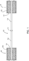
- Figure 1 shows a cavity 10 between adjacent ends of pipe line lengths 11 and 12 each comprising a pipe 13, insulation material 14 and a cylindrical pipe jacket 16, usually of polymer material.
- the ends of the pipes 13 are left bare to allow the ends to be welded together at 17.
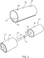
- a resiliently flexible coil form sheet 18 is employed as shown in Fig. 2 .
- a foam insulation body 30 is formed in contact with an inner surface of the sheet 18, which functions as a mold sheet.
- the sheet 18 adopts a cylindrical coil condition.
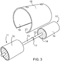
- the sheet 18 is partially uncoiled and is lowered over the joint and, as seen in Figs. 3 and 4 is positioned in an encircling position around the joint.
- the sheet 18 is selected so that its width provides an axial length such that its sides overlap the adjacent ends of the pipe jackets 16, as seen in Fig. 6 .
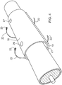
- the resilient sheet 18 is selected so that, in the relaxed condition, seen in fig. 2 , its diameter is less than that of the jackets 16 while its circumferential length is such that, in the fitted position, shown in Fig. 4 , the ends 19 and 21 overlap, with the sheet 18 in a resiliently expanded condition.
- the resilient reaction causes the sheet 18 to grip tightly around the adjacent end portions of the jackets 16 and is retained in position by the resultant frictional forces.
- the frictional gripping greatly facilitates positioning of the sheet 18 around the cavity 10 to form a mold.
- the resiliently flexible coil form sheet 18 is a fibre reinforced plastic sheet, such as that available from Clock Spring Company, Long Beach, California.
- the preferred fibres used to form the composite resilient fibre reinforced plastic sheet 18 have a Young's modulus of at least 50 GPa.
- Such fibres will include glass, aramid fibre (for example Kevlar (trade-mark) available from Dupont), carbon and steel fibres.
- the resin employed in making the composite may include epoxy, polyester, polyurethane, phenolics, nylons, and others known to those skilled in the art.
- a glass fibre filled epoxy resin sheet may be employed. Such sheet typically provides a Young's modulus of 10 GPa (as measured by ASTM D638). As a further example, a unidirectional glass fibre filled epoxy resin sheet may be employed. Such sheet provides a Young's modulus of greater than 20 GPa (ASTM D638).
- securing elements in the form of straps 22, are applied on the sheet 18, as seen in Figs. 4 and 5 .
- the straps 22 are passed around mold sheet 18 and their ends are provided with inter-engaging tensioning elements 23 allowing the straps 22 to be tensioned by adjustment of the tensioning devices 23.
- tensioning devices may be employed. The tension in the straps 22 resists any tendency for circumferential separating movement of the overlapped ends 19 and 21 on expansion of the subsequently introduced foam filling.
- Sheet 18 is provided with fill and vent openings 26 and 27.
- a liquid precursor 29 of a foamable curable resin composition is introduced through the fill opening 26.
- a funnel 28 may be inserted through the opening 26 to assist positioning of the precursor 29 within the cavity 10.
- the liquid precursor 29 may be, for example, be a two-part urethane foam composition that is mixed shortly before introducing it through the opening 26.
- the liquid precursor 29 expands within the cavity, and cures to form a rigid foam filling 30.
- the straps 22 are removed and the sheet 18 is stripped away, exposing the foamed and cured filling 30 in the form of an annular body of diameter substantially similar or equal to the diameter of the pipe casings 16.
- the inside of the mold sheet 18 is coated with a release agent to make the sheet 18 readily cleanly strippable from the foam filling 30.
- This coating may be provided by, for example, a silicone release coating spray or a brushed on coating of carnauba wax composition.
- the sheet 18 may be lined with a release liner sheet, for example wax paper or a polyolefin, for example, a polyethylene film coated with silicone.
- a rubber gasket tape may be applied circumferentially over the pipe jackets 16 adjacent to the cavity and under the mold sheet 18 to prevent foam leakage from the cavity during expansion.
- the foam filling 30 is sealed in water tight fashion by applying tapes of a adhesive sealant 34 around the ends of the pipe jackets 16, and applying a heat shrinkable polymeric casing 36 over the sealant tapes 32 and 34, as seen in Fig. 8 and applying heat, at least to the end portions of the casing 36 overlying the sealant tapes 32 and 34, to heat shrink the casing 36 in tight sealing engagement with the adhesive sealant tapes 32 and 34 and with the adjacent portions of the pipe jackets 16. In some instances the entire casing 36 may be heat shrunk over the joint.
- the adhesive sealant tapes 32 and 34 and heat shrinkable casing 36 are applied before applying the mold sheet 18, and the foam insulation body 30 is formed in contact with an inner surface of the casing 36.
- the sheet 18 in this example functions as a flexible tensile member that resists ballooning of the casing 36 on expansion of the foam precursor 29.
- heat shielding bands 38 for example high temperature resistant heat insulating bands, such as glass fibre fabric bands, are applied around the casing 36 axially inwardly adjacent the ends of the pipe jacket 16.
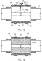
- the ends of the casing 36 are then shrunk down into tight sealing engagement with the sealant tapes 32, 34 and with the ends of the jackets 16, as seen in Fig. 11 , for example by applying a gas torch 35 on the ends of the casing 36.
- fill and vent openings 41 and 42 are formed through the wall of the casing 36, for example by drilling through the wall. These openings 41 and 42 positioned in registry with the fill and vent openings 26 and 27, respectively, in the subsequently applied sheet 18.
- a temporary foaming plug 43 is inserted as a stopper within the opening 41, to encourage the foam to fill the cavity 10 within the casing 36 without excessive leakage of foam through the fill opening 41.
- the straps 22 and sheet 18 are removed.
- the temporary foaming plug 43 is removed, and polymeric filler plugs 44 and 46 are inserted within the fill and vent openings 41 and 42, respectively, and welded in place in order to seal the casing 36 in water tight fashion.
- the casing 36 is formed with its wall having outer and inner layers 36a and 36b, the inner layer 36b being uncrosslinked or crosslinked to a lesser degree of crosslinking than the outer layer 36a, which is crosslinked to a substantially greater degree, so that the polymeric plugs 44 and 46a will weld readily to the portions 36b bordering the holes 41 and 42 formed through the casing 36.
- This two layer structure for the wall of the casing 36 may be provided by laminating sheets of the materials 36a and 36b together to form a composite sheet, and forming a tubular sleeve from the composite sheet in conventional fashion.
- the casing 36 may have a wall thickness which is constant across the width of the sleeve. If desired, however, a casing which has its middle portion of greater wall thickness than its end portions, such as described in our above-mentioned U.S. patent 6,355,318 may be employed.
- the greater wall thickness of the middle portion reduces any tendency for the casing to shrink into the cavity 10 in the course of heating the end portions of the casing as described above with reference to Figure 11 . This eliminates the need for the use of heat shielding bands 38 to prevent shrinking of the casing into the cavity 10.
- the sheet 18 in the above-described procedures allows a relatively thin-walled casing 36 to be employed, if desired, since the casing need not be in itself capable of withstanding the pressure of the expanding foam during the course of forming and curing the film within the cavity 10. This function of withstanding the pressure of the foam is performed by the sheet 18.
- a casing similar to casing 36 shown in Fig. 10 , of wall thickness greater than about 12 mm to avoid ballooning.
- a casing 36 with wall thickness of 6 mm was employed on the 1000 mm joint.
- An anti-ballooning sheet 18 comprising glass fibre reinforced epoxy resin was employed.
- the foam filling 30 comprised polyurethane foam formed from a two-part urethane foam composition mixed together to provide the liquid precursor 29. After the precursor 29 had fully foamed and set, it was found the circumference of the casing had expanded less than 2%, with no visually perceptible ballooning.
- the mold sheet may be a metal sheet.
- an aluminum sheet typically having a Young's modulus of 69 GPa, may be employed.
- a further example of material as equally effectively as the above-described fiber reinforced plastic sheet or metal sheet comprises flexible fabric sheets, for example, flexible fabric sheets formed of high tensile fibres such as para-aramid (trade-mark KEVLAR) or high tensile glass fibres.
- Such metal sheets and fabric sheets are employed in the same manner as the mold sheets 18, as described above with reference to Figs. 1 to 14 , except in the case in which the sheets are not in the form of a resilient coil, the sheets need to be supported once wrapped around the cavity 10, until secured in place by the straps 22.
- a further example as illustrated for example in Fig. 15 flexible tensile members in the form of strap elements 51 are applied around the casing.
- the procedure is otherwise similar to that described above with reference to Figs. 9 to 14a .
- the strap elements 51 are tensioned using conventional strap tensioning devices so that they engage snugly around the casing 36 before the foam filling precursor 29 is introduced.
- the strap elements 51 may be, for example, conventional polypropylene or nylon webbing straps woven from, for example, multifilament yarn.
Description
- The present invention relates to method for foam filling a cavity in a joint between insulated pipe lengths.
- Such method and apparatus are known, for example, from our
U.S. Patent No. 6,355,318 issued March 12, 2002 . - Known methods and apparatus of which the applicant is aware employ relatively sturdy heat shrinkable casings for surrounding the foam filling that are designed to withstand the stresses to which the casings are subjected in use, for example the stress that the foam exerts on the casing as it expands to fill the cavity in the course of foam filling the joint.
- The use of heavy weight heat-shrinkable casings may not always be desirable or economically advantageous, however.
- One example relates to a method wherein foam filling may be pre-formed before applying a casing around the filling. In this aspect, the invention provides a method of foam filling a cavity in a joint between insulated pipe lengths, comprising wrapping around the cavity a mold sheet comprising a fibre reinforced plastic sheet and having opposing ends overlapped to form a cylindrical mold; introducing a curable foam precursor in said cavity; the mold sheet having tensile strength that resists ballooning of the foam filling on expansion thereof from curable foam precursor; applying securing elements on the mold to resist circumferential separating movement of the overlapped ends upon expansion of the filling; allowing said precursor to foam and cure; and removing said securing elements and said mold sheet. The fibre reinforced plastic sheet provides the advantages of offering excellent resistance to ballooning while being of relatively light weight.
- An aspect according to the invention relates to providing a casing around the cavity before foam filling. In this aspect the invention provides a method of foam filling a cavity in a joint between insulated pipe lengths, comprising applying a casing around the cavity, wrapping at least one flexible tensile member around the casing; introducing a curable foam precursor in said cavity through an opening in the casing; allowing said precursor to foam and cure; the flexible member having tensile strength that resists ballooning of the casing on expansion of the foam filling from the curable foam precursor; including the step of applying a securing element on the flexible member to resist girthwise extension of the flexible member on expansion of the filling; and removing said flexible member and said securing element.
- The at least one flexible tensile member may comprise two or more strap elements, for example conventional polypropylene or nylon webbing straps woven from, for example, multifilament yarn.
- In one preferred form, the flexible member is a flexible sheet having opposing ends overlapped.
- A further example provides an apparatus for foam filling a cavity in a joint between insulated pipe lengths, comprising a fibre reinforced plastic sheet having opposing ends that can be overlapped to form a cylindrical mold wrapped around the cavity, and securing elements that apply on the sheet to resist circumferential separation of the overlapped ends of the sheet on expansion of the filling.
- The above aspects of the present invention allow a relatively thin walled casing to be employed, if desired, since it need not be capable of withstanding the pressure of the expanding foam, as that function is performed by the flexible tensile member.
- The fibre reinforced plastic or other sheet provides a particularly convenient way of providing a stress-resisting mold around the insulated pipeline joint cavity.
- The tensile strength required for the sheet or flexible member to resist ballooning when the foam expands may be readily determined in any given case by simple trial and experiment.
- "Ballooning" refers to expansion of the sheet or of the casing that is visible to the eye.
- In preferred forms, the sheet or flexible member has a Young's modulus, as measuring by ASTM D638 (or ASTM D6775-02 in the case of textile webbing) of at least 5-25 GPa, more preferably at least 15 GPa.
- The foregoing will be more fully described, by way of example only with reference to the accompanying drawings, in which:
-
Figure 1 shows a side view, partly in cross-section through a joint between insulated pipe lengths, and the cavity therebetween. -
Figures 2 to 5 are perspective views andfigures 6 to 8 are schematic side views, partially in cross-section, illustrating steps in forming a foam insulation filling in the cavity. -
Figures 9 through 14 are schematic side views, partially in cross-section, illustrating steps in forming a foam filling in such cavity according to the invention. -
Figure 14A is a cross-section taken on the lines A-A inFigure 14 , and -
Figure 15 is a schematic side view, partially in section illustrating a third embodiment of ballooning resistant structure. -
Figure 1 shows acavity 10 between adjacent ends ofpipe line lengths pipe 13,insulation material 14 and acylindrical pipe jacket 16, usually of polymer material. - The ends of the
pipes 13 are left bare to allow the ends to be welded together at 17. - In one form of the present example, a resiliently flexible
coil form sheet 18 is employed as shown inFig. 2 . - In the example described below with reference to
Figs. 2 to 8 , afoam insulation body 30 is formed in contact with an inner surface of thesheet 18, which functions as a mold sheet. - As seen in
Fig. 2 in a relaxed condition, thesheet 18 adopts a cylindrical coil condition. In one preferred example of the present method, as seen inFig. 3 , thesheet 18 is partially uncoiled and is lowered over the joint and, as seen inFigs. 3 and4 is positioned in an encircling position around the joint. Thesheet 18 is selected so that its width provides an axial length such that its sides overlap the adjacent ends of thepipe jackets 16, as seen inFig. 6 . - In a preferred form, the
resilient sheet 18 is selected so that, in the relaxed condition, seen infig. 2 , its diameter is less than that of thejackets 16 while its circumferential length is such that, in the fitted position, shown inFig. 4 , theends sheet 18 in a resiliently expanded condition. In this condition, the resilient reaction causes thesheet 18 to grip tightly around the adjacent end portions of thejackets 16 and is retained in position by the resultant frictional forces. As will be appreciated, the frictional gripping greatly facilitates positioning of thesheet 18 around thecavity 10 to form a mold. - While other similar resiliently flexible coil form sheet material may be employed, in one preferred form, the resiliently flexible
coil form sheet 18 is a fibre reinforced plastic sheet, such as that available from Clock Spring Company, Long Beach, California. - The preferred fibres used to form the composite resilient fibre reinforced
plastic sheet 18 have a Young's modulus of at least 50 GPa. Such fibres will include glass, aramid fibre (for example Kevlar (trade-mark) available from Dupont), carbon and steel fibres. The resin employed in making the composite may include epoxy, polyester, polyurethane, phenolics, nylons, and others known to those skilled in the art. - For example, a glass fibre filled epoxy resin sheet may be employed. Such sheet typically provides a Young's modulus of 10 GPa (as measured by ASTM D638). As a further example, a unidirectional glass fibre filled epoxy resin sheet may be employed. Such sheet provides a Young's modulus of greater than 20 GPa (ASTM D638).
- As seen in
Figs. 4 and5 , securing elements, in the form ofstraps 22, are applied on thesheet 18, as seen inFigs. 4 and5 . In this example, thestraps 22 are passed aroundmold sheet 18 and their ends are provided withinter-engaging tensioning elements 23 allowing thestraps 22 to be tensioned by adjustment of thetensioning devices 23. Various conventional forms of tensioning devices may be employed. The tension in thestraps 22 resists any tendency for circumferential separating movement of theoverlapped ends -
Sheet 18 is provided with fill andvent openings Fig. 6 , aliquid precursor 29 of a foamable curable resin composition is introduced through the fill opening 26. Afunnel 28 may be inserted through the opening 26 to assist positioning of theprecursor 29 within thecavity 10. Theliquid precursor 29 may be, for example, be a two-part urethane foam composition that is mixed shortly before introducing it through the opening 26. Theliquid precursor 29 expands within the cavity, and cures to form a rigid foam filling 30. Once the composition is fully foamed and cured, thestraps 22 are removed and thesheet 18 is stripped away, exposing the foamed and cured filling 30 in the form of an annular body of diameter substantially similar or equal to the diameter of thepipe casings 16. - Desirably, the inside of the
mold sheet 18 is coated with a release agent to make thesheet 18 readily cleanly strippable from the foam filling 30. This coating may be provided by, for example, a silicone release coating spray or a brushed on coating of carnauba wax composition. Alternatively, thesheet 18 may be lined with a release liner sheet, for example wax paper or a polyolefin, for example, a polyethylene film coated with silicone. - A rubber gasket tape may be applied circumferentially over the
pipe jackets 16 adjacent to the cavity and under themold sheet 18 to prevent foam leakage from the cavity during expansion. - In the preferred form, the foam filling 30 is sealed in water tight fashion by applying tapes of a
adhesive sealant 34 around the ends of thepipe jackets 16, and applying a heat shrinkablepolymeric casing 36 over thesealant tapes Fig. 8 and applying heat, at least to the end portions of thecasing 36 overlying thesealant tapes casing 36 in tight sealing engagement with theadhesive sealant tapes pipe jackets 16. In some instances theentire casing 36 may be heat shrunk over the joint. - An embodiment of the invention is described below with reference to
Figs. 9 through 14A . - Elements similar to those employed in the procedure described above with reference to
Figs. 1 to 8 are identified by the same reference numerals for the sake of convenience of description. - However, in this example, the
adhesive sealant tapes heat shrinkable casing 36 are applied before applying themold sheet 18, and thefoam insulation body 30 is formed in contact with an inner surface of thecasing 36. Further, thesheet 18 in this example functions as a flexible tensile member that resists ballooning of thecasing 36 on expansion of thefoam precursor 29. - To prevent a tendency for the
casing 36 to shrink down into thecavity 10,heat shielding bands 38, for example high temperature resistant heat insulating bands, such as glass fibre fabric bands, are applied around thecasing 36 axially inwardly adjacent the ends of thepipe jacket 16. The ends of thecasing 36 are then shrunk down into tight sealing engagement with thesealant tapes jackets 16, as seen inFig. 11 , for example by applying agas torch 35 on the ends of thecasing 36. - Before or after shrinking, fill and
vent openings casing 36, for example by drilling through the wall. Theseopenings vent openings sheet 18. - The procedure then generally follows that described above with reference to
figs. 2 to 6 , except thesheet 18 is applied on an exterior side of thecasing 36. - If desired, once a sufficient quantity of the
foam precursor 29 has been introduced through thefill hole 41, atemporary foaming plug 43 is inserted as a stopper within theopening 41, to encourage the foam to fill thecavity 10 within thecasing 36 without excessive leakage of foam through thefill opening 41. - Once the foam has fully formed, and has filled the
cavity 10 within thecasing 36 and has cured, thestraps 22 andsheet 18 are removed. Thetemporary foaming plug 43 is removed, and polymeric filler plugs 44 and 46 are inserted within the fill and ventopenings casing 36 in water tight fashion. - In order to facilitate welding of the
plugs crosslinked casing 36, thecasing 36 is formed with its wall having outer andinner layers inner layer 36b being uncrosslinked or crosslinked to a lesser degree of crosslinking than theouter layer 36a, which is crosslinked to a substantially greater degree, so that the polymeric plugs 44 and 46a will weld readily to theportions 36b bordering theholes casing 36. This two layer structure for the wall of thecasing 36 may be provided by laminating sheets of thematerials - In the examples described above, the
casing 36 may have a wall thickness which is constant across the width of the sleeve. If desired, however, a casing which has its middle portion of greater wall thickness than its end portions, such as described in our above-mentionedU.S. patent 6,355,318 may be employed. The greater wall thickness of the middle portion reduces any tendency for the casing to shrink into thecavity 10 in the course of heating the end portions of the casing as described above with reference toFigure 11 . This eliminates the need for the use ofheat shielding bands 38 to prevent shrinking of the casing into thecavity 10. - As noted above, the
sheet 18 in the above-described procedures allows a relatively thin-walled casing 36 to be employed, if desired, since the casing need not be in itself capable of withstanding the pressure of the expanding foam during the course of forming and curing the film within thecavity 10. This function of withstanding the pressure of the foam is performed by thesheet 18. - For example, with known procedures before the present invention, in the case of a large diameter insulated pipeline joint, having a
jacket 16 of external diameter 1000 mm, it was necessary to use a casing, similar tocasing 36 shown inFig. 10 , of wall thickness greater than about 12 mm to avoid ballooning. In the same circumstances, using the procedure of one aspect of the invention as described above with reference toFigs. 9 to 14a , acasing 36 with wall thickness of 6 mm was employed on the 1000 mm joint. Ananti-ballooning sheet 18 comprising glass fibre reinforced epoxy resin was employed. The foam filling 30 comprised polyurethane foam formed from a two-part urethane foam composition mixed together to provide theliquid precursor 29. After theprecursor 29 had fully foamed and set, it was found the circumference of the casing had expanded less than 2%, with no visually perceptible ballooning. - While fibre reinforced plastic sheet materials have been described above as examples of one form of
sheet material 18 providing sufficient tensile strength to withstand the foam pressure and avoid any tendency for ballooning, other materials that perform this function may, of course, be employed. For example, the mold sheet may be a metal sheet. For example, an aluminum sheet, typically having a Young's modulus of 69 GPa, may be employed. A further example of material as equally effectively as the above-described fiber reinforced plastic sheet or metal sheet comprises flexible fabric sheets, for example, flexible fabric sheets formed of high tensile fibres such as para-aramid (trade-mark KEVLAR) or high tensile glass fibres. - Such metal sheets and fabric sheets are employed in the same manner as the
mold sheets 18, as described above with reference toFigs. 1 to 14 , except in the case in which the sheets are not in the form of a resilient coil, the sheets need to be supported once wrapped around thecavity 10, until secured in place by thestraps 22. - Instead of applying an
anti-ballooning sheet 18 around thecasing 36, as described above with reference toFigs. 9 to 14a , in a further example as illustrated for example inFig. 15 , flexible tensile members in the form ofstrap elements 51 are applied around the casing. The procedure is otherwise similar to that described above with reference toFigs. 9 to 14a . Thestrap elements 51 are tensioned using conventional strap tensioning devices so that they engage snugly around thecasing 36 before thefoam filling precursor 29 is introduced. - The
strap elements 51 may be, for example, conventional polypropylene or nylon webbing straps woven from, for example, multifilament yarn.
Claims (8)
- Method of foam filling a cavity in a joint between insulated pipe lengths, comprising applying a casing (36) around the cavity, wrapping at least one flexible tensile member (18) around the casing (36); introducing a curable foam precursor (29) in said cavity through an opening in the casing; allowing said precursor (30) to foam and cure; the flexible member (18) having tensile strength that resists ballooning of the casing (36) on expansion of the foam filling from the curable foam precursor; including the step of applying a securing element (22) on the flexible member (18) to resist girthwise extension of the flexible member (18) on expansion of the filling; and removing said flexible member (18) and said securing element (22), wherein the casing comprises an inner layer and an outerlayer and the inner layer is uncrosslinked or is crosslinked to a lesser degree than the outer layer.
- Method according to claim 1 wherein said casing (36) is at least partially heat shrinkable and including shrinking at least portions of said casing (36) into tight contact with the insulated pipe lengths (16) adjacent the joint.
- Method according to claim 1 or 2 wherein said at least one flexible member (18) comprises at least two strap elements.
- Method according to claim 1 or 2 wherein said at least one flexible member (18) is a flexible sheet having opposing ends overlapped.
- Method according to claim 4 wherein said flexible sheet is a fibre reinforced plastic sheet comprising a resiliently flexible coil.
- Method according to claim 4 wherein said flexible sheet is a metal sheet.
- Method according to claim 4 wherein said flexible sheet is a flexible fabric sheet comprising high tensile fibres.
- Method according to claim 7 wherein said fibres are para-aramid or glass fibres.
Priority Applications (1)
| Application Number | Priority Date | Filing Date | Title |
|---|---|---|---|
| PL09832758T PL2379299T3 (en) | 2008-12-19 | 2009-12-09 | Method of filling a casing |
Applications Claiming Priority (2)
| Application Number | Priority Date | Filing Date | Title |
|---|---|---|---|
| CA2647972A CA2647972A1 (en) | 2008-12-19 | 2008-12-19 | Method of filling a casing |
| PCT/CA2009/001750 WO2010069044A1 (en) | 2008-12-19 | 2009-12-09 | Method of filling a casing |
Publications (3)
| Publication Number | Publication Date |
|---|---|
| EP2379299A1 EP2379299A1 (en) | 2011-10-26 |
| EP2379299A4 EP2379299A4 (en) | 2013-09-25 |
| EP2379299B1 true EP2379299B1 (en) | 2018-11-28 |
Family
ID=42263353
Family Applications (1)
| Application Number | Title | Priority Date | Filing Date |
|---|---|---|---|
| EP09832758.8A Not-in-force EP2379299B1 (en) | 2008-12-19 | 2009-12-09 | Method of filling a casing |
Country Status (9)
| Country | Link |
|---|---|
| US (1) | US9393723B2 (en) |
| EP (1) | EP2379299B1 (en) |
| KR (1) | KR101799405B1 (en) |
| CA (2) | CA2647972A1 (en) |
| PL (1) | PL2379299T3 (en) |
| RO (1) | RO128020A8 (en) |
| RU (1) | RU2524723C2 (en) |
| SG (1) | SG172120A1 (en) |
| WO (1) | WO2010069044A1 (en) |
Families Citing this family (30)
| Publication number | Priority date | Publication date | Assignee | Title |
|---|---|---|---|---|
| DK2304299T3 (en) | 2008-06-09 | 2018-01-15 | Flexsteel Pipeline Tech Inc | COLLECTION FOR FLEXIBLE PIPES. |
| KR200474498Y1 (en) * | 2012-05-25 | 2014-09-25 | 박수조 | Connection member for hot-water supply pipe |
| DE102012017167A1 (en) * | 2012-08-30 | 2014-03-06 | isoplus Fernwärmetechnik GmbH | Method for connecting jacketed medium pipes |
| GB2519816B (en) * | 2013-10-31 | 2016-05-25 | Subsea 7 Ltd | Techniques for coating pipes |
| DK178155B1 (en) * | 2014-06-16 | 2015-07-06 | Pipeteq Systems As | A process for producing a branch on a pre-insulated pipe |
| EP3201509B1 (en) | 2014-09-30 | 2020-01-01 | Flexsteel Pipeline Technologies, Inc. | Connector for pipes |
| DK3209483T3 (en) * | 2014-10-24 | 2021-01-04 | Shawcor Ltd | Method for attaching a cladding to an outer sheath of a pipe joint |
| CN108474521B (en) | 2015-11-02 | 2021-04-09 | 柔性钢管道技术公司 | Real-time integrity monitoring of onshore pipelines |
| US10981765B2 (en) | 2016-06-28 | 2021-04-20 | Trinity Bay Equipment Holdings, LLC | Half-moon lifting device |
| US11208257B2 (en) | 2016-06-29 | 2021-12-28 | Trinity Bay Equipment Holdings, LLC | Pipe coil skid with side rails and method of use |
| CN109996749B (en) | 2016-10-10 | 2021-01-12 | 圣三一海湾设备控股有限公司 | Installation trailer for coiled flexible pipe and method of use thereof |
| WO2018071299A1 (en) | 2016-10-10 | 2018-04-19 | Trinity Bay Equipment Holdings, LLC | Expandable drum assembly for deploying coiled pipe and method of using same |
| US10526164B2 (en) | 2017-08-21 | 2020-01-07 | Trinity Bay Equipment Holdings, LLC | System and method for a flexible pipe containment sled |
| WO2019089747A1 (en) | 2017-11-01 | 2019-05-09 | Trinity Bay Equipment Holdings, LLC | System and method for handling reel of pipe |
| CN107763356A (en) * | 2017-11-17 | 2018-03-06 | 北京豪特耐管道设备有限公司 | A kind of utilidor joint design and its construction method |
| WO2019152779A2 (en) | 2018-02-01 | 2019-08-08 | Trinity Bay Equipment Holdings, LLC | Pipe coil skid with side rails and method of use |
| AR114640A1 (en) | 2018-02-22 | 2020-09-30 | Trinity Bay Equipment Holdings Llc | SYSTEM AND METHOD FOR DEPLOYING ROLLER TUBE COILS |
| KR102149532B1 (en) * | 2018-04-16 | 2020-08-31 | 주식회사 국일인토트 | Pre-insulated pipe casing and installation method the same |
| US11066002B2 (en) | 2018-10-12 | 2021-07-20 | Trinity Bay Equipment Holdings, LLC | Installation trailer for coiled flexible pipe and method of utilizing same |
| AR118122A1 (en) | 2019-02-15 | 2021-09-22 | Trinity Bay Equipment Holdings Llc | FLEXIBLE TUBE HANDLING SYSTEM AND METHOD TO USE THE SAME |
| US10753512B1 (en) | 2019-03-28 | 2020-08-25 | Trinity Bay Equipment Holdings, LLC | System and method for securing fittings to flexible pipe |
| US10926972B1 (en) | 2019-11-01 | 2021-02-23 | Trinity Bay Equipment Holdings, LLC | Mobile cradle frame for pipe reel |
| MX2022006233A (en) | 2019-11-22 | 2022-08-22 | Trinity Bay Equipment Holdings Llc | Swaged pipe fitting systems and methods. |
| CN114981581A (en) | 2019-11-22 | 2022-08-30 | 圣三一海湾设备控股有限公司 | Canned tube fitting system and method |
| US10822194B1 (en) | 2019-12-19 | 2020-11-03 | Trinity Bay Equipment Holdings, LLC | Expandable coil deployment system for drum assembly and method of using same |
| US10844976B1 (en) | 2020-02-17 | 2020-11-24 | Trinity Bay Equipment Holdings, LLC | Methods and apparatus for pulling flexible pipe |
| WO2021168041A1 (en) * | 2020-02-19 | 2021-08-26 | Dow Silicones Corporation | Method for the in-situ encapsulation and/or insulation of piping |
| RU2744369C1 (en) * | 2020-04-15 | 2021-03-05 | Вячеслав Николаевич Войтенко | Device for manufacture of blocks of foamed polymeric materials (options) and method of manufacturing such blocks |
| US11725766B2 (en) * | 2020-11-09 | 2023-08-15 | Epoxy Design Systems, Inc. | Systems and methods for repairing piping |
| KR102433096B1 (en) * | 2021-11-26 | 2022-08-18 | 화성엔지니어링 주식회사 | Pipe leak repair unit |
Family Cites Families (20)
| Publication number | Priority date | Publication date | Assignee | Title |
|---|---|---|---|---|
| US3731710A (en) * | 1965-08-27 | 1973-05-08 | Exxon | Spray foam insulated pipe |
| GB1176418A (en) * | 1967-05-01 | 1970-01-01 | Exxon Research Engineering Co | Spray Foam Insulated Pipe |
| SU553391A1 (en) * | 1974-11-01 | 1977-04-05 | Ленинградский зональный научно-исследовательский и проектный институт типового и экспериментального проектирования жилых и общественных зданий | Installation for applying thermal insulation to a pipe |
| CA1179211A (en) * | 1982-11-12 | 1984-12-11 | Dilip K. Tailor | Heat shrinkable covering and method for applying same |
| ATE45210T1 (en) * | 1983-05-25 | 1989-08-15 | Shaw Ind Ltd | HEAT SHRINK CUFF. |
| GB8507374D0 (en) * | 1985-03-21 | 1985-05-01 | Raychem Sa Nv | Coated recoverable articles |
| US4909669A (en) | 1986-07-28 | 1990-03-20 | Ralph Baker | Pipeline joint protector |
| US4746147A (en) | 1987-04-09 | 1988-05-24 | Ecw, Inc. | Pipe joint |
| US5175032A (en) * | 1991-05-02 | 1992-12-29 | Shaw Industries Ltd. | Heat shrinkable closure sheets and sleeve structures and methods employing the same |
| US5489405A (en) * | 1991-08-14 | 1996-02-06 | Foam Enterprises, Inc. | Composite joint infill system |
| US5490742A (en) * | 1993-06-04 | 1996-02-13 | Cronk; Tommy J. | Modular protective pipeline cover |
| FR2735416B1 (en) | 1995-06-13 | 1997-08-29 | D Auria Stanislas Boulet | FLEXIBLE FABRIC SLEEVE AS AN INJECTION MOLD |
| US5804093A (en) * | 1995-11-02 | 1998-09-08 | Foam Enterprises, Inc. | Joint infill mold |
| US5736715A (en) * | 1996-03-19 | 1998-04-07 | Thermacor Process, Inc. | Method of forming pressure testable joint between insulated pipes using split sleeve arrangement |
| US5900195A (en) * | 1996-08-12 | 1999-05-04 | Urethane Products International | Protection of pipeline joint connections |
| GB2319316A (en) | 1996-11-14 | 1998-05-20 | Shaw Ind Ltd | Heat shrinkable member for connecting tubular sections |
| GB9905037D0 (en) * | 1999-03-05 | 1999-04-28 | Raychem Sa Nv | Method of sealing a joint between two pipes |
| CA2276708A1 (en) * | 1999-06-30 | 2000-12-30 | Shaw Industries Ltd. | Casing with provision for closing an opening therein |
| US7407197B2 (en) * | 2004-09-17 | 2008-08-05 | Offshore Joint Services, Inc. | Pipe joint infill and protective sleeve |
| US7472476B2 (en) * | 2005-09-21 | 2009-01-06 | Offshore Joint Services, Inc. | Method of applying joint infill cladding to pipe |
-
2008
- 2008-12-19 CA CA2647972A patent/CA2647972A1/en not_active Abandoned
-
2009
- 2009-12-09 CA CA2747559A patent/CA2747559C/en not_active Expired - Fee Related
- 2009-12-09 PL PL09832758T patent/PL2379299T3/en unknown
- 2009-12-09 RO ROA201100573A patent/RO128020A8/en unknown
- 2009-12-09 RU RU2011124170/05A patent/RU2524723C2/en not_active IP Right Cessation
- 2009-12-09 WO PCT/CA2009/001750 patent/WO2010069044A1/en active Application Filing
- 2009-12-09 KR KR1020117016792A patent/KR101799405B1/en active Search and Examination
- 2009-12-09 US US13/140,621 patent/US9393723B2/en active Active
- 2009-12-09 EP EP09832758.8A patent/EP2379299B1/en not_active Not-in-force
- 2009-12-09 SG SG2011043049A patent/SG172120A1/en unknown
Non-Patent Citations (1)
| Title |
|---|
| None * |
Also Published As
| Publication number | Publication date |
|---|---|
| US9393723B2 (en) | 2016-07-19 |
| CA2647972A1 (en) | 2010-06-19 |
| PL2379299T3 (en) | 2019-05-31 |
| KR101799405B1 (en) | 2017-11-20 |
| RO128020A2 (en) | 2012-12-28 |
| RU2524723C2 (en) | 2014-08-10 |
| KR20110114585A (en) | 2011-10-19 |
| CA2747559A1 (en) | 2010-06-24 |
| RO128020B1 (en) | 2015-03-30 |
| RU2011124170A (en) | 2013-01-27 |
| EP2379299A1 (en) | 2011-10-26 |
| RO128020A8 (en) | 2015-03-30 |
| CA2747559C (en) | 2014-02-11 |
| SG172120A1 (en) | 2011-07-28 |
| US20120223452A1 (en) | 2012-09-06 |
| EP2379299A4 (en) | 2013-09-25 |
| WO2010069044A1 (en) | 2010-06-24 |
Similar Documents
| Publication | Publication Date | Title |
|---|---|---|
| EP2379299B1 (en) | Method of filling a casing | |
| US4622196A (en) | Lining of pipelines and passageways | |
| US7258141B2 (en) | Pipe liner apparatus and method | |
| CA2799812C (en) | Casing member for forming a connection between tubular sections and use thereof for forming connections | |
| EP2142837B1 (en) | Bladderless pipeliner and method for using same | |
| US11168827B2 (en) | Method of and system for coating a field joint of a pipe | |
| GB2319316A (en) | Heat shrinkable member for connecting tubular sections | |
| AU651092B2 (en) | Pipeline and passageway lining materials | |
| NO310170B1 (en) | Ambient Seal | |
| EP0188363A1 (en) | Preinsulated pipeline joint | |
| JP5260126B2 (en) | Resin tube with cap | |
| EP0119073A1 (en) | Reinsulation of pipe joints | |
| US8545656B2 (en) | Method of manufacturing resin pipe | |
| CA2291821A1 (en) | Apparatus and method for lining of passageways | |
| JP5783089B2 (en) | Method and apparatus for anticorrosion coating of steel weld joint | |
| JP2020056476A (en) | Composite pipe and joining method for composite pipe | |
| JPS5858554B2 (en) | How to fasten plastic hoses |
Legal Events
| Date | Code | Title | Description |
|---|---|---|---|
| PUAI | Public reference made under article 153(3) epc to a published international application that has entered the european phase |
Free format text: ORIGINAL CODE: 0009012 |
|
| 17P | Request for examination filed |
Effective date: 20110719 |
|
| AK | Designated contracting states |
Kind code of ref document: A1 Designated state(s): AT BE BG CH CY CZ DE DK EE ES FI FR GB GR HR HU IE IS IT LI LT LU LV MC MK MT NL NO PL PT RO SE SI SK SM TR |
|
| RIN1 | Information on inventor provided before grant (corrected) |
Inventor name: KLEJMAN, AARON Inventor name: TRAPMANN, DIETER Inventor name: TAILOR, DILIP Inventor name: LAFERRIERE, PASCAL |
|
| DAX | Request for extension of the european patent (deleted) | ||
| A4 | Supplementary search report drawn up and despatched |
Effective date: 20130828 |
|
| RIC1 | Information provided on ipc code assigned before grant |
Ipc: F16L 59/20 20060101ALI20130822BHEP Ipc: F16L 55/175 20060101ALI20130822BHEP Ipc: B29C 65/42 20060101ALI20130822BHEP Ipc: B29C 44/12 20060101ALI20130822BHEP Ipc: F16L 59/18 20060101ALI20130822BHEP Ipc: B29C 44/18 20060101AFI20130822BHEP |
|
| 17Q | First examination report despatched |
Effective date: 20140818 |
|
| RIC1 | Information provided on ipc code assigned before grant |
Ipc: B29C 44/12 20060101ALI20180201BHEP Ipc: B29L 23/00 20060101ALN20180201BHEP Ipc: F16L 55/175 20060101ALI20180201BHEP Ipc: F16L 59/18 20060101ALI20180201BHEP Ipc: F16L 47/22 20060101ALI20180201BHEP Ipc: B29C 65/42 20060101ALI20180201BHEP Ipc: B29C 44/18 20060101AFI20180201BHEP Ipc: F16L 59/20 20060101ALI20180201BHEP |
|
| GRAP | Despatch of communication of intention to grant a patent |
Free format text: ORIGINAL CODE: EPIDOSNIGR1 |
|
| RIC1 | Information provided on ipc code assigned before grant |
Ipc: B29C 65/42 20060101ALI20180606BHEP Ipc: B29C 44/12 20060101ALI20180606BHEP Ipc: B29L 23/00 20060101ALN20180606BHEP Ipc: F16L 47/22 20060101ALI20180606BHEP Ipc: F16L 55/175 20060101ALI20180606BHEP Ipc: B29C 44/18 20060101AFI20180606BHEP Ipc: F16L 59/20 20060101ALI20180606BHEP Ipc: F16L 59/18 20060101ALI20180606BHEP |
|
| INTG | Intention to grant announced |
Effective date: 20180621 |
|
| GRAS | Grant fee paid |
Free format text: ORIGINAL CODE: EPIDOSNIGR3 |
|
| GRAA | (expected) grant |
Free format text: ORIGINAL CODE: 0009210 |
|
| AK | Designated contracting states |
Kind code of ref document: B1 Designated state(s): AT BE BG CH CY CZ DE DK EE ES FI FR GB GR HR HU IE IS IT LI LT LU LV MC MK MT NL NO PL PT RO SE SI SK SM TR |
|
| REG | Reference to a national code |
Ref country code: GB Ref legal event code: FG4D |
|
| REG | Reference to a national code |
Ref country code: CH Ref legal event code: EP |
|
| REG | Reference to a national code |
Ref country code: DE Ref legal event code: R096 Ref document number: 602009055958 Country of ref document: DE |
|
| REG | Reference to a national code |
Ref country code: AT Ref legal event code: REF Ref document number: 1069693 Country of ref document: AT Kind code of ref document: T Effective date: 20181215 |
|
| REG | Reference to a national code |
Ref country code: IE Ref legal event code: FG4D |
|
| REG | Reference to a national code |
Ref country code: NL Ref legal event code: MP Effective date: 20181128 |
|
| REG | Reference to a national code |
Ref country code: LT Ref legal event code: MG4D |
|
| REG | Reference to a national code |
Ref country code: AT Ref legal event code: MK05 Ref document number: 1069693 Country of ref document: AT Kind code of ref document: T Effective date: 20181128 |
|
| PG25 | Lapsed in a contracting state [announced via postgrant information from national office to epo] |
Ref country code: BG Free format text: LAPSE BECAUSE OF FAILURE TO SUBMIT A TRANSLATION OF THE DESCRIPTION OR TO PAY THE FEE WITHIN THE PRESCRIBED TIME-LIMIT Effective date: 20190228 Ref country code: IS Free format text: LAPSE BECAUSE OF FAILURE TO SUBMIT A TRANSLATION OF THE DESCRIPTION OR TO PAY THE FEE WITHIN THE PRESCRIBED TIME-LIMIT Effective date: 20190328 Ref country code: LT Free format text: LAPSE BECAUSE OF FAILURE TO SUBMIT A TRANSLATION OF THE DESCRIPTION OR TO PAY THE FEE WITHIN THE PRESCRIBED TIME-LIMIT Effective date: 20181128 Ref country code: HR Free format text: LAPSE BECAUSE OF FAILURE TO SUBMIT A TRANSLATION OF THE DESCRIPTION OR TO PAY THE FEE WITHIN THE PRESCRIBED TIME-LIMIT Effective date: 20181128 Ref country code: LV Free format text: LAPSE BECAUSE OF FAILURE TO SUBMIT A TRANSLATION OF THE DESCRIPTION OR TO PAY THE FEE WITHIN THE PRESCRIBED TIME-LIMIT Effective date: 20181128 Ref country code: ES Free format text: LAPSE BECAUSE OF FAILURE TO SUBMIT A TRANSLATION OF THE DESCRIPTION OR TO PAY THE FEE WITHIN THE PRESCRIBED TIME-LIMIT Effective date: 20181128 Ref country code: NO Free format text: LAPSE BECAUSE OF FAILURE TO SUBMIT A TRANSLATION OF THE DESCRIPTION OR TO PAY THE FEE WITHIN THE PRESCRIBED TIME-LIMIT Effective date: 20190228 Ref country code: AT Free format text: LAPSE BECAUSE OF FAILURE TO SUBMIT A TRANSLATION OF THE DESCRIPTION OR TO PAY THE FEE WITHIN THE PRESCRIBED TIME-LIMIT Effective date: 20181128 |
|
| PG25 | Lapsed in a contracting state [announced via postgrant information from national office to epo] |
Ref country code: PT Free format text: LAPSE BECAUSE OF FAILURE TO SUBMIT A TRANSLATION OF THE DESCRIPTION OR TO PAY THE FEE WITHIN THE PRESCRIBED TIME-LIMIT Effective date: 20190328 Ref country code: GR Free format text: LAPSE BECAUSE OF FAILURE TO SUBMIT A TRANSLATION OF THE DESCRIPTION OR TO PAY THE FEE WITHIN THE PRESCRIBED TIME-LIMIT Effective date: 20190301 Ref country code: SE Free format text: LAPSE BECAUSE OF FAILURE TO SUBMIT A TRANSLATION OF THE DESCRIPTION OR TO PAY THE FEE WITHIN THE PRESCRIBED TIME-LIMIT Effective date: 20181128 |
|
| PG25 | Lapsed in a contracting state [announced via postgrant information from national office to epo] |
Ref country code: NL Free format text: LAPSE BECAUSE OF FAILURE TO SUBMIT A TRANSLATION OF THE DESCRIPTION OR TO PAY THE FEE WITHIN THE PRESCRIBED TIME-LIMIT Effective date: 20181128 |
|
| REG | Reference to a national code |
Ref country code: DE Ref legal event code: R119 Ref document number: 602009055958 Country of ref document: DE |
|
| PG25 | Lapsed in a contracting state [announced via postgrant information from national office to epo] |
Ref country code: IT Free format text: LAPSE BECAUSE OF FAILURE TO SUBMIT A TRANSLATION OF THE DESCRIPTION OR TO PAY THE FEE WITHIN THE PRESCRIBED TIME-LIMIT Effective date: 20181128 Ref country code: CZ Free format text: LAPSE BECAUSE OF FAILURE TO SUBMIT A TRANSLATION OF THE DESCRIPTION OR TO PAY THE FEE WITHIN THE PRESCRIBED TIME-LIMIT Effective date: 20181128 Ref country code: DK Free format text: LAPSE BECAUSE OF FAILURE TO SUBMIT A TRANSLATION OF THE DESCRIPTION OR TO PAY THE FEE WITHIN THE PRESCRIBED TIME-LIMIT Effective date: 20181128 |
|
| REG | Reference to a national code |
Ref country code: CH Ref legal event code: PL |
|
| PG25 | Lapsed in a contracting state [announced via postgrant information from national office to epo] |
Ref country code: MC Free format text: LAPSE BECAUSE OF FAILURE TO SUBMIT A TRANSLATION OF THE DESCRIPTION OR TO PAY THE FEE WITHIN THE PRESCRIBED TIME-LIMIT Effective date: 20181128 Ref country code: SK Free format text: LAPSE BECAUSE OF FAILURE TO SUBMIT A TRANSLATION OF THE DESCRIPTION OR TO PAY THE FEE WITHIN THE PRESCRIBED TIME-LIMIT Effective date: 20181128 Ref country code: RO Free format text: LAPSE BECAUSE OF FAILURE TO SUBMIT A TRANSLATION OF THE DESCRIPTION OR TO PAY THE FEE WITHIN THE PRESCRIBED TIME-LIMIT Effective date: 20181128 Ref country code: LU Free format text: LAPSE BECAUSE OF NON-PAYMENT OF DUE FEES Effective date: 20181209 Ref country code: EE Free format text: LAPSE BECAUSE OF FAILURE TO SUBMIT A TRANSLATION OF THE DESCRIPTION OR TO PAY THE FEE WITHIN THE PRESCRIBED TIME-LIMIT Effective date: 20181128 Ref country code: SM Free format text: LAPSE BECAUSE OF FAILURE TO SUBMIT A TRANSLATION OF THE DESCRIPTION OR TO PAY THE FEE WITHIN THE PRESCRIBED TIME-LIMIT Effective date: 20181128 |
|
| REG | Reference to a national code |
Ref country code: IE Ref legal event code: MM4A |
|
| PLBE | No opposition filed within time limit |
Free format text: ORIGINAL CODE: 0009261 |
|
| STAA | Information on the status of an ep patent application or granted ep patent |
Free format text: STATUS: NO OPPOSITION FILED WITHIN TIME LIMIT |
|
| REG | Reference to a national code |
Ref country code: BE Ref legal event code: MM Effective date: 20181231 |
|
| GBPC | Gb: european patent ceased through non-payment of renewal fee |
Effective date: 20190228 |
|
| PG25 | Lapsed in a contracting state [announced via postgrant information from national office to epo] |
Ref country code: DE Free format text: LAPSE BECAUSE OF NON-PAYMENT OF DUE FEES Effective date: 20190702 Ref country code: SI Free format text: LAPSE BECAUSE OF FAILURE TO SUBMIT A TRANSLATION OF THE DESCRIPTION OR TO PAY THE FEE WITHIN THE PRESCRIBED TIME-LIMIT Effective date: 20181128 Ref country code: IE Free format text: LAPSE BECAUSE OF NON-PAYMENT OF DUE FEES Effective date: 20181209 |
|
| 26N | No opposition filed |
Effective date: 20190829 |
|
| PG25 | Lapsed in a contracting state [announced via postgrant information from national office to epo] |
Ref country code: BE Free format text: LAPSE BECAUSE OF NON-PAYMENT OF DUE FEES Effective date: 20181231 |
|
| PG25 | Lapsed in a contracting state [announced via postgrant information from national office to epo] |
Ref country code: LI Free format text: LAPSE BECAUSE OF NON-PAYMENT OF DUE FEES Effective date: 20181231 Ref country code: CH Free format text: LAPSE BECAUSE OF NON-PAYMENT OF DUE FEES Effective date: 20181231 |
|
| PG25 | Lapsed in a contracting state [announced via postgrant information from national office to epo] |
Ref country code: GB Free format text: LAPSE BECAUSE OF NON-PAYMENT OF DUE FEES Effective date: 20190228 Ref country code: MT Free format text: LAPSE BECAUSE OF NON-PAYMENT OF DUE FEES Effective date: 20181209 |
|
| PGFP | Annual fee paid to national office [announced via postgrant information from national office to epo] |
Ref country code: FI Payment date: 20191220 Year of fee payment: 11 |
|
| PGFP | Annual fee paid to national office [announced via postgrant information from national office to epo] |
Ref country code: PL Payment date: 20191202 Year of fee payment: 11 Ref country code: FR Payment date: 20191230 Year of fee payment: 11 |
|
| PG25 | Lapsed in a contracting state [announced via postgrant information from national office to epo] |
Ref country code: TR Free format text: LAPSE BECAUSE OF FAILURE TO SUBMIT A TRANSLATION OF THE DESCRIPTION OR TO PAY THE FEE WITHIN THE PRESCRIBED TIME-LIMIT Effective date: 20181128 |
|
| PG25 | Lapsed in a contracting state [announced via postgrant information from national office to epo] |
Ref country code: HU Free format text: LAPSE BECAUSE OF FAILURE TO SUBMIT A TRANSLATION OF THE DESCRIPTION OR TO PAY THE FEE WITHIN THE PRESCRIBED TIME-LIMIT; INVALID AB INITIO Effective date: 20091209 Ref country code: MK Free format text: LAPSE BECAUSE OF NON-PAYMENT OF DUE FEES Effective date: 20181128 Ref country code: CY Free format text: LAPSE BECAUSE OF FAILURE TO SUBMIT A TRANSLATION OF THE DESCRIPTION OR TO PAY THE FEE WITHIN THE PRESCRIBED TIME-LIMIT Effective date: 20181128 |
|
| REG | Reference to a national code |
Ref country code: FI Ref legal event code: MAE |
|
| PG25 | Lapsed in a contracting state [announced via postgrant information from national office to epo] |
Ref country code: FI Free format text: LAPSE BECAUSE OF NON-PAYMENT OF DUE FEES Effective date: 20201209 |
|
| PG25 | Lapsed in a contracting state [announced via postgrant information from national office to epo] |
Ref country code: FR Free format text: LAPSE BECAUSE OF NON-PAYMENT OF DUE FEES Effective date: 20201231 |
|
| PG25 | Lapsed in a contracting state [announced via postgrant information from national office to epo] |
Ref country code: PL Free format text: LAPSE BECAUSE OF NON-PAYMENT OF DUE FEES Effective date: 20201209 |